EP2112772A1 - Method for reducing interference in a radio network equipment and equipment performing the method - Google Patents
Method for reducing interference in a radio network equipment and equipment performing the method Download PDFInfo
- Publication number
- EP2112772A1 EP2112772A1 EP08300192A EP08300192A EP2112772A1 EP 2112772 A1 EP2112772 A1 EP 2112772A1 EP 08300192 A EP08300192 A EP 08300192A EP 08300192 A EP08300192 A EP 08300192A EP 2112772 A1 EP2112772 A1 EP 2112772A1
- Authority
- EP
- European Patent Office
- Prior art keywords
- signal
- cross
- receiver equipment
- equipment
- interference
- Prior art date
- Legal status (The legal status is an assumption and is not a legal conclusion. Google has not performed a legal analysis and makes no representation as to the accuracy of the status listed.)
- Granted
Links
- 238000000034 method Methods 0.000 title claims abstract description 17
- 238000004590 computer program Methods 0.000 claims description 2
- 230000005855 radiation Effects 0.000 description 6
- 230000005540 biological transmission Effects 0.000 description 5
- 208000037957 feline spongiform encephalopathy Diseases 0.000 description 4
- 238000005388 cross polarization Methods 0.000 description 3
- 230000000694 effects Effects 0.000 description 3
- 101150071716 PCSK1 gene Proteins 0.000 description 2
- 239000000969 carrier Substances 0.000 description 2
- 230000015556 catabolic process Effects 0.000 description 2
- 238000006243 chemical reaction Methods 0.000 description 2
- 238000006731 degradation reaction Methods 0.000 description 2
- 230000006870 function Effects 0.000 description 2
- 238000002955 isolation Methods 0.000 description 2
- 230000010287 polarization Effects 0.000 description 2
- 230000001427 coherent effect Effects 0.000 description 1
- 230000001143 conditioned effect Effects 0.000 description 1
- 238000011084 recovery Methods 0.000 description 1
- 230000001360 synchronised effect Effects 0.000 description 1
Images



Classifications
-
- H—ELECTRICITY
- H04—ELECTRIC COMMUNICATION TECHNIQUE
- H04B—TRANSMISSION
- H04B7/00—Radio transmission systems, i.e. using radiation field
- H04B7/02—Diversity systems; Multi-antenna system, i.e. transmission or reception using multiple antennas
- H04B7/04—Diversity systems; Multi-antenna system, i.e. transmission or reception using multiple antennas using two or more spaced independent antennas
- H04B7/08—Diversity systems; Multi-antenna system, i.e. transmission or reception using multiple antennas using two or more spaced independent antennas at the receiving station
- H04B7/0802—Diversity systems; Multi-antenna system, i.e. transmission or reception using multiple antennas using two or more spaced independent antennas at the receiving station using antenna selection
- H04B7/0805—Diversity systems; Multi-antenna system, i.e. transmission or reception using multiple antennas using two or more spaced independent antennas at the receiving station using antenna selection with single receiver and antenna switching
- H04B7/0808—Diversity systems; Multi-antenna system, i.e. transmission or reception using multiple antennas using two or more spaced independent antennas at the receiving station using antenna selection with single receiver and antenna switching comparing all antennas before reception
-
- H—ELECTRICITY
- H04—ELECTRIC COMMUNICATION TECHNIQUE
- H04B—TRANSMISSION
- H04B1/00—Details of transmission systems, not covered by a single one of groups H04B3/00 - H04B13/00; Details of transmission systems not characterised by the medium used for transmission
- H04B1/38—Transceivers, i.e. devices in which transmitter and receiver form a structural unit and in which at least one part is used for functions of transmitting and receiving
- H04B1/40—Circuits
- H04B1/50—Circuits using different frequencies for the two directions of communication
- H04B1/52—Hybrid arrangements, i.e. arrangements for transition from single-path two-direction transmission to single-direction transmission on each of two paths or vice versa
- H04B1/525—Hybrid arrangements, i.e. arrangements for transition from single-path two-direction transmission to single-direction transmission on each of two paths or vice versa with means for reducing leakage of transmitter signal into the receiver
-
- H—ELECTRICITY
- H04—ELECTRIC COMMUNICATION TECHNIQUE
- H04B—TRANSMISSION
- H04B7/00—Radio transmission systems, i.e. using radiation field
- H04B7/02—Diversity systems; Multi-antenna system, i.e. transmission or reception using multiple antennas
- H04B7/10—Polarisation diversity; Directional diversity
Definitions
- the present invention relates to wireless transmission.
- the invention relates to reducing interference.
- the invention relates to front-to-back interference in point-to-point wireless transmission systems with antenna arrangement having low angular discrimination.
- wireless communication usually requires a transmitter equipment and a receiver equipment.
- the transmitter and the receiver equipment typically use antennas.
- both the transmitter antenna and the receiver antenna are installed on the same site, for example on the same tower or building.
- the signal transmitted from the transmitter equipment is at the same frequency as that of the signal received by the receiver equipment, i . e . they use the same frequency channel. This may occur, for example, when different values of frequencies are not available due to the fact that radio resources are limited.
- the use of the same frequency channels may give rise to the so called front-to-back interference. This problem is particularly more likely to arise when the angular discrimination between the transmitter antenna and the receiver antenna in the same location is relatively low, for example less than 90°. Therefore, it may be desirable to avoid such relatively low angular discriminations.
- the setting of the angular discrimination between the transmitter antenna and the receiver antenna is in many occasions conditioned by factors which in practice would not allow for a free choice of a desirable value, for example factors such as the physical location of the sites which communicate with each other or even the availability of space on the tower on which the two antennas are to be installed or the particular geographical conditions where the paths are arranged.
- sites A, B and C are adapted to communicate with each other for example using point-to-point communication.
- site A is assumed to have a transmitting antenna which is pointed towards the remote receiving site C.
- site A is assumed to have a receiving antenna which is pointed towards a remote transmitting site B.
- site A transmits a signal to site C using transmission frequency CHx and receives a signal from site B using the same transmission frequency CHx.
- the location of the respective receiving and transmitting remote sites C and B conditions the angular discrimination, ⁇ in this case, between the transmitting and receiving antennas of the site A and as the same frequency is used in transmission and reception at site A, this site is likely to experience front-to-back interference (assuming that the angle ⁇ is relatively low as discussed above).
- the invention proposes the use of a Cross-Polar Interference Canceller (XPIC) comprised in a receiver equipment which may be subject to interference, in order to reduce the iso-frequency (co-channel) interference likely to be generated by the transmitted signal transmitted from a neighboring antenna with not enough angular discrimination so as to avoid interference.
- Cross-polarization interference cancellers XPIC are known devices which are commonly used in order to reduce mutual interference of two signals travelling over the same carrier frequency, but on opposite polarisation to negligible levels.
- the XPIC is capable of providing what is known as an improvement factor sufficient to increase the carrier-to-interference ratio at a level where the effect of co-channel interference is substantially eliminated or at least reduced to a negligible level such that degradation in the performance of the system is substantially absent.
- Cross-Polarization Isolation as defined for two radio waves transmitted with the same power and orthogonal polarizations, is the ratio at the reception point of the power level of a first radio wave received with respect to the second radio wave received, in the expected polarization of the first wave.
- the system operating at the same frequency channel on orthogonal polarisation in the same route can transmit double capacity signal rather than that of the interleaved use.
- the improvement factor (XPIF) of the XPIC is the Cross-Polarization Isolation (XPI) difference between a performance with XPIC and a performance without XPIC at specified carrier-to-interference ratio C/I and BER conditions.
- the carrier-to-interference ratio (C/I, also known as CIR), is known in the art to represent a ratio between the average power of a modulated carrier and the average power of a co-channel interference as received by the same receiver.
- the first signal and the second signal have respective frequencies being substantially close to each other in value.
- the first and the second signal have the same frequency.
- a receiver equipment adapted for receiving a receive signal from a first antenna and a cross-polar interference signal from a second antenna adjacent to the first antenna, wherein the receiver equipment comprises a cross-polar interference canceller adapted for receiving the receive signal and the cross-polar interference signal , the receiver equipment having
- the cross-polar interference canceller comprises a at least two branches, each of the at least two branches comprising a mixer and a fractionally spaced equalizer and further comprising a clock unit for providing clock signal to each of the at least two branches and a combiner for combining respective outputs of the fractionally spaced equalizers of the at least two branches.
- a computer readable storage means having a message therein, such computer readable storage means containing program code means corresponding to a program for the implementation of the steps of the method of the invention, when this program is run on a computer, an ASIC, an FPGA or a microprocessor.
- the invention proposes the use of an XPIC device in a receiver equipment in order to reduce the interference level of the co-channel signal coming from the adjacent antenna, as already discussed above.
- a front-to-back interference could be produced by a transmitter equipment over a signal at the same frequency received at a receiver equipment.
- Figure 2 schematically shows an exemplary arrangement including a receiver equipment 1 and a transmitter equipment 2. It is assumed that the receiver equipment 1 receives signals in a first direction d1 and the transmitter equipment 2 transmits signals in a second direction d2, where d1 and d2 are at an angle ⁇ with respect to each other. This angle ⁇ represents the angular discrimination between the receiver equipment 1 and the transmitter equipment 2. It is further assumed that angle ⁇ has a value less than 90°.
- the receiver equipment 1 typically comprises a receiver unit 11 and a demodulator 12.
- the received radio frequency (RF) signal is filtered and then amplified in the receiver unit 11 with a very low noise amplifier.
- the signal is subsequently downconverted to the desired intermediate frequency (IF) and is then amplified.
- the microwave power required for the conversion is supplied by a local oscillator.
- the signal is then bandlimited in an IF filter, amplified to a constant level in the main IF amplifier and fed to the demodulator 12.
- the IF signal is baseband converted by means of two mixers that are controlled by a carrier recovery circuit.
- the transmitter equipment 2 typically comprises a transmitter unit 21 and a modulator 22.
- two IF in-quadrature carriers are modulated by two filtered signals by means of two balanced mixers. Then, modulated carriers are summed in order to generate a multi-level QAM modulated signal.
- the IF signal coming from the modulator is fed to an IF amplifier.
- the amplifier chain recovers the cable loss, in order to have a constant level at the input of the IF amplifier.
- the signal from the IF amplifier is fed to an up-converter.
- the IF signal is up-converted to RF frequencies.
- the output signal of the up-converter is fed to an RF power amplifier with a defined output power.
- the receiver equipment 1 further comprises a Cross-Polar Interference Canceller (XPIC) 13. As shown in figure 2 , the XPIC 13 is connected to the demodulator 12 of the receiver equipment 1 and also to the modulator 22 of the transmitter equipment 2.
- XPIC Cross-Polar Interference Canceller
- the modulator 22 inputs a signal into the XPIC containing an Intermediate Frequency (IF) contribution of the signal which is to be transmitted from transmitter equipment 2.
- IF Intermediate Frequency
- This IF contribution conveys information in order to allow the XPIC to distinguish the undesired component, namely to distinguish the component of the received signal related to the interference by the transmitter equipment, from the useful (desired) signal, and cancel the undesired component.
- the cancelling operation of the XPIC will be described further below in relation to figure 4 .
- antenna radiation pattern an example of which is shown in the plotted graph of figure 3 .
- antenna radiation patterns are typically provided by the manufacturers.
- attenuation is shown in the ordinate in dB and angular discrimination is shown in the abscissa in degrees (it is to be noted that a part of this axis, from 0 to 15° is shown in "expanded scale" as compared to the rest of the values higher than 15° It is assumed that:
- FIG 4 is a schematic representation of a cross-polar interference canceller (XPIC) 13 showing only certain elements thereof for the purpose of better understanding this description.
- the XPIC has two branches A and B.
- branch A there is shown a mixer 131, a low-pass filter 133 and a fractionally spaced equalizer (FSE) 135.
- branch B there is shown a mixer 132, a low-pass filter 134 and a fractionally spaced equalizer (FSE) 136.
- a voltage controlled oscillator (VCO) 130 is used as a clock which is common to both branches.
- the two branches are then fed into a combiner 139.
- the corresponding elements of the branches are preferably identical in type and functionality.
- a signal is input in branch A and another signal is input in branch B. It is assumed that from these two signals one is the desired signal (the signal to be recovered) and the other is the cross-polar interference (thus undesired) signal.
- FSEs may be used, with a modified Uyematsu-Sakaniwa algorithm. FSEs are insensitive to a quadrature error on the receive side and so there is no need for a circuit for quadrature control.
- Carrier synchronisation is based on synchronous down conversion and coherent demodulation of the two signals.
- a clock signal 130 is fed into both mixers 131 and 132. It is assumed that the mixer 131 receives at its input in branch A the desired wave (namely the signal received the direction d1 as shown in figure 2 ) and the mixer 132 receives at its input the undesired signal (namely the signal received in the direction d2 as shown in figure 2 ).
- the input signals are clocked in the respective mixers 131 and 132, shaped in the respective low-pass filters 133 and 134 and fed into the respective FSEs 135 and 136.
- the outputs of the FSEs 135 and 136 are input into a combiner which is used in order to decide which of the two waves is to be selected.
- MMSE Minimum Mean Square Error
- the signal that has a respective power value greater than the respective power value of the other signal is selected.
- the signal that has a respective BER value lower than the respective BER value of the other signal is selected
- the signal that has a respective power value greater than the respective power value of the other signal and a respective BER value lower than the respective BER value of the other signal is selected.
- the desired signal which is the signal received in the direction d1 is recovered and thus front-to-back interference caused by the signal in the direction d2 and generated by the transmitter located nearby is cancelled.
- the performance of the fractionally spaced equaliser is insensitive to the timing instant, thus only the synchronization of the clock frequency is required and the cross-polar wave (in this example, the wave input in the FSE 136 of branch B) requires only coarse adjustment of the differential delay between the two paths.
- the use of the XPIC improves significantly the level of attenuation caused by front-to-back interference.
- the improvement in performance achieved by using an XPIC is shown analytically and also by means of a numerical example.
- One advantage of the proposed solution is that it may help overcome at least some problems caused by network congestion and may help to improve system performance, because it allows a reduction of the angular discrimination of the antennas where the topology of the network requires to install antennas on the same tower and the limited number of available frequencies requires the re-use of the same frequency in a particular nodal arrangement.
- the proposed solution can also be applied to a multi-channel arrangement configuration, where N receivers are interfered by N transmitter operating at the same corresponding frequencies.
- the receiver equipment and/or the transmitter equipment may include blocks which can be hardware devices, software modules or combination of hardware devices and software modules.
- This method can be advantageously implemented on equipment including means such as an Application Specific Integrated Circuit (ASIC), a Field Programmable Gate Array (FPGA) and/or a microprocessor, and in a preferred embodiment through or together with a software program like Very high speed integrated circuit Hardware Description Language (VHDL) or C programming language. Therefore, it is understood that the scope of the protection is extended to such a program product and in addition to a computer readable storage means having a message therein, such computer readable storage means contain program code means for the implementation of one or more steps of the method, when this program is run on a computer, an ASIC, an FPGA or a microprocessor.
- ASIC Application Specific Integrated Circuit
- FPGA Field Programmable Gate Array
- VHDL Very high speed integrated circuit Hardware Description Language
- receiver equipment of the invention can be used to practice another and materially different method and is not be construed to be limited to practicing only the method as claimed in the present invention.
- the method of the invention can be practiced by another materially different system, device, apparatus or equipment than the one(s) claimed in the present invention.
Landscapes
- Engineering & Computer Science (AREA)
- Computer Networks & Wireless Communication (AREA)
- Signal Processing (AREA)
- Noise Elimination (AREA)
Abstract
Description
- The present invention relates to wireless transmission. In particular the invention relates to reducing interference. More particularly, the invention relates to front-to-back interference in point-to-point wireless transmission systems with antenna arrangement having low angular discrimination.
- As it is well known, wireless communication usually requires a transmitter equipment and a receiver equipment. The transmitter and the receiver equipment typically use antennas. In practice, it may occur that the transmitter antenna and the receiver antenna are installed very close to each other. In many occasions, both the transmitter antenna and the receiver antenna are installed on the same site, for example on the same tower or building.
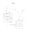
- Also in many occasions it may occur that the signal transmitted from the transmitter equipment is at the same frequency as that of the signal received by the receiver equipment, i.e. they use the same frequency channel. This may occur, for example, when different values of frequencies are not available due to the fact that radio resources are limited. The use of the same frequency channels may give rise to the so called front-to-back interference. This problem is particularly more likely to arise when the angular discrimination between the transmitter antenna and the receiver antenna in the same location is relatively low, for example less than 90°. Therefore, it may be desirable to avoid such relatively low angular discriminations. However, the setting of the angular discrimination between the transmitter antenna and the receiver antenna is in many occasions conditioned by factors which in practice would not allow for a free choice of a desirable value, for example factors such as the physical location of the sites which communicate with each other or even the availability of space on the tower on which the two antennas are to be installed or the particular geographical conditions where the paths are arranged. One example of such situation is schematically shown in
figure 1 , wherein sites A, B and C are adapted to communicate with each other for example using point-to-point communication. In this example, site A is assumed to have a transmitting antenna which is pointed towards the remote receiving site C. Furthermore, site A is assumed to have a receiving antenna which is pointed towards a remote transmitting site B. As shown, site A transmits a signal to site C using transmission frequency CHx and receives a signal from site B using the same transmission frequency CHx. The location of the respective receiving and transmitting remote sites C and B conditions the angular discrimination, α in this case, between the transmitting and receiving antennas of the site A and as the same frequency is used in transmission and reception at site A, this site is likely to experience front-to-back interference (assuming that the angle α is relatively low as discussed above). - The invention proposes the use of a Cross-Polar Interference Canceller (XPIC) comprised in a receiver equipment which may be subject to interference, in order to reduce the iso-frequency (co-channel) interference likely to be generated by the transmitted signal transmitted from a neighboring antenna with not enough angular discrimination so as to avoid interference. Cross-polarization interference cancellers (XPIC) are known devices which are commonly used in order to reduce mutual interference of two signals travelling over the same carrier frequency, but on opposite polarisation to negligible levels.
- The XPIC is capable of providing what is known as an improvement factor sufficient to increase the carrier-to-interference ratio at a level where the effect of co-channel interference is substantially eliminated or at least reduced to a negligible level such that degradation in the performance of the system is substantially absent.
- Cross-Polarization Isolation (XPI) as defined for two radio waves transmitted with the same power and orthogonal polarizations, is the ratio at the reception point of the power level of a first radio wave received with respect to the second radio wave received, in the expected polarization of the first wave. The system operating at the same frequency channel on orthogonal polarisation in the same route (co-channel system) can transmit double capacity signal rather than that of the interleaved use.
- The improvement factor (XPIF) of the XPIC is the Cross-Polarization Isolation (XPI) difference between a performance with XPIC and a performance without XPIC at specified carrier-to-interference ratio C/I and BER conditions.
- The carrier-to-interference ratio (C/I, also known as CIR), is known in the art to represent a ratio between the average power of a modulated carrier and the average power of a co-channel interference as received by the same receiver.
- Accordingly there is provided a method for reducing interference between at least two adjacent antennas comprising the steps of:
- transmitting a first signal from a transmitter equipment
- receiving a second signal by a receiver equipment
- inputting the first and the second signal into a cross-polar interference canceller, included in the receiver equipment
- calculating a respective power and/or a respective BER of the first and the second signals
- selecting between the first signal and the second signal the signal that has its respective power greater than the respective power of the other signal, or the one that has its respective BER lower than the respective BER of the other signal; or
- selecting between the first signal and the second signal the signal that has its respective power greater than the respective power of the other signal and has its respective BER lower than the respective BER of the other signal.
- According to one embodiment, the first signal and the second signal have respective frequencies being substantially close to each other in value. According to another, the first and the second signal have the same frequency. Furthermore, there is provided a receiver equipment adapted for receiving a receive signal from a first antenna and a cross-polar interference signal from a second antenna adjacent to the first antenna, wherein the receiver equipment comprises a cross-polar interference canceller adapted for receiving the receive signal and the cross-polar interference signal , the receiver equipment having
- means for calculating a respective power and/or a respective BER of the receive signal and the cross-polar interference signal
- means for selecting between the receive signal and the cross-polar interference based on said calculated values of respective power, or respective BER individually or in combination.
- According to one embodiment, the cross-polar interference canceller comprises a at least two branches, each of the at least two branches comprising a mixer and a fractionally spaced equalizer and further comprising a clock unit for providing clock signal to each of the at least two branches and a combiner for combining respective outputs of the fractionally spaced equalizers of the at least two branches.
- There is further provided a computer program product for the implementation of the steps of the method of the invention, when this program is run on a computer, an ASIC, an FPGA or a microprocessor.
- Furthermore, there is provided a computer readable storage means having a message therein, such computer readable storage means containing program code means corresponding to a program for the implementation of the steps of the method of the invention, when this program is run on a computer, an ASIC, an FPGA or a microprocessor.
-
-
Figure 1 , already described, schematically represents an exemplary communication scenario with receiving and transmitting sites. -
Figure 2 is a schematic representation of an arrangement including a receiver equipment and a transmitter equipment wherein the front-to-back interference may be reduced. -
Figure 3 is an exemplary plot graph of an antenna radiation pattern -
Figure 4 is a schematic representation of elements of a Cross-Polar Interference Canceller. - The invention proposes the use of an XPIC device in a receiver equipment in order to reduce the interference level of the co-channel signal coming from the adjacent antenna, as already discussed above. In a nodal configuration, where the frequency allocation is a scarce resource, a front-to-back interference could be produced by a transmitter equipment over a signal at the same frequency received at a receiver equipment.
-
Figure 2 schematically shows an exemplary arrangement including areceiver equipment 1 and a transmitter equipment 2. It is assumed that thereceiver equipment 1 receives signals in a first direction d1 and the transmitter equipment 2 transmits signals in a second direction d2, where d1 and d2 are at an angle α with respect to each other. This angle α represents the angular discrimination between thereceiver equipment 1 and the transmitter equipment 2. It is further assumed that angle α has a value less than 90°. - Therefore, if the frequency of the signal received by the
receiver equipment 1 is the same, or substantially close, to the frequency of the signal transmitted by the transmitter equipment 2, then front-to-back interference occurs in thereceiver equipment 1 caused by the effect of the signal transmitted by transmitter equipment 2 on thereceiver equipment 1. - The
receiver equipment 1 typically comprises areceiver unit 11 and a demodulator 12. - The received radio frequency (RF) signal is filtered and then amplified in the
receiver unit 11 with a very low noise amplifier. The signal is subsequently downconverted to the desired intermediate frequency (IF) and is then amplified. The microwave power required for the conversion is supplied by a local oscillator. The signal is then bandlimited in an IF filter, amplified to a constant level in the main IF amplifier and fed to the demodulator 12. The IF signal is baseband converted by means of two mixers that are controlled by a carrier recovery circuit. - The transmitter equipment 2 typically comprises a
transmitter unit 21 and amodulator 22. - In a typical implementation, two IF in-quadrature carriers are modulated by two filtered signals by means of two balanced mixers. Then, modulated carriers are summed in order to generate a multi-level QAM modulated signal. The IF signal coming from the modulator is fed to an IF amplifier. The amplifier chain, recovers the cable loss, in order to have a constant level at the input of the IF amplifier. The signal from the IF amplifier is fed to an up-converter. Next the IF signal is up-converted to RF frequencies. The output signal of the up-converter is fed to an RF power amplifier with a defined output power.
- According to the invention, the
receiver equipment 1 further comprises a Cross-Polar Interference Canceller (XPIC) 13. As shown infigure 2 , theXPIC 13 is connected to the demodulator 12 of thereceiver equipment 1 and also to themodulator 22 of the transmitter equipment 2. - The
modulator 22 inputs a signal into the XPIC containing an Intermediate Frequency (IF) contribution of the signal which is to be transmitted from transmitter equipment 2. This IF contribution conveys information in order to allow the XPIC to distinguish the undesired component, namely to distinguish the component of the received signal related to the interference by the transmitter equipment, from the useful (desired) signal, and cancel the undesired component. The cancelling operation of the XPIC will be described further below in relation tofigure 4 . - In order to obtain corresponding values for attenuation as a function of angular discrimination, use is made of an antenna radiation pattern, an example of which is shown in the plotted graph of
figure 3 . It is to be noted that antenna radiation patterns are typically provided by the manufacturers. Infigure 3 , attenuation is shown in the ordinate in dB and angular discrimination is shown in the abscissa in degrees (it is to be noted that a part of this axis, from 0 to 15° is shown in "expanded scale" as compared to the rest of the values higher than 15°
It is assumed that: - PTx
- is the power of the transmitted signal [in dBm]
- PRx
- is the power of the received signal [in dBm]
- C/I
- is the carrier to interference ratio
- XPIF
- is the improvement factor of the XPIC [in dB]
- α
- is the angular discrimination between the two antennas
- Att
- is the attenuation [in dB] of the peak signal as a function of angle α obtained from the antenna radiation pattern (
figure 3 ). - Assuming that:
- PRx= -60dBm
- [this being a typical value]
- PTx=+30dBm
- [this being a typical value]
- C/I=30dB
- [this being a typical value for a system transmitting an STM-1 carrier using a modulation scheme of 128-states],
XPIF=30dB - The difference in attenuation as shown in the example above make it possible to achieve a reduction in the acceptable (operational) value of the angular discrimination from 90° up to 40°, as can be appreciated from the difference in values of Att(1) and Att(2) in conjunction with the antenna radiation pattern of
figure 3 . Using this solution therefore, provides the possibility of achieving an improvement factor (XPIF) of about 30dB provided by the XPIC while at the same time any effect due to the front-to-back interference is avoided or substantially reduced. -
Figure 4 is a schematic representation of a cross-polar interference canceller (XPIC) 13 showing only certain elements thereof for the purpose of better understanding this description. The XPIC has two branches A and B. In branch A there is shown amixer 131, a low-pass filter 133 and a fractionally spaced equalizer (FSE) 135. Likewise, in branch B there is shown amixer 132, a low-pass filter 134 and a fractionally spaced equalizer (FSE) 136. A voltage controlled oscillator (VCO) 130 is used as a clock which is common to both branches. The two branches are then fed into a combiner 139. The corresponding elements of the branches are preferably identical in type and functionality. - A signal is input in branch A and another signal is input in branch B. It is assumed that from these two signals one is the desired signal (the signal to be recovered) and the other is the cross-polar interference (thus undesired) signal.
- As a practical example of implementation, four dimensional 19 taps FSEs may be used, with a modified Uyematsu-Sakaniwa algorithm. FSEs are insensitive to a quadrature error on the receive side and so there is no need for a circuit for quadrature control. Carrier synchronisation is based on synchronous down conversion and coherent demodulation of the two signals. A
clock signal 130 is fed into bothmixers mixer 131 receives at its input in branch A the desired wave (namely the signal received the direction d1 as shown infigure 2 ) and themixer 132 receives at its input the undesired signal (namely the signal received in the direction d2 as shown infigure 2 ). The input signals are clocked in therespective mixers pass filters respective FSEs FSEs - At this stage, estimated values of the power and the Minimum Mean Square Error (MMSE) of the signals at the respective output of each
FSE - Then according to one option, the signal that has a respective power value greater than the respective power value of the other signal is selected.
- According to another option, the signal that has a respective BER value lower than the respective BER value of the other signal is selected
- According to a further option, the signal that has a respective power value greater than the respective power value of the other signal and a respective BER value lower than the respective BER value of the other signal is selected.
- In this manner the desired signal, which is the signal received in the direction d1 is recovered and thus front-to-back interference caused by the signal in the direction d2 and generated by the transmitter located nearby is cancelled.
- It is noted that the performance of the fractionally spaced equaliser is insensitive to the timing instant, thus only the synchronization of the clock frequency is required and the cross-polar wave (in this example, the wave input in the
FSE 136 of branch B) requires only coarse adjustment of the differential delay between the two paths. - The use of the XPIC improves significantly the level of attenuation caused by front-to-back interference. In the following, the improvement in performance achieved by using an XPIC is shown analytically and also by means of a numerical example.
- One advantage of the proposed solution is that it may help overcome at least some problems caused by network congestion and may help to improve system performance, because it allows a reduction of the angular discrimination of the antennas where the topology of the network requires to install antennas on the same tower and the limited number of available frequencies requires the re-use of the same frequency in a particular nodal arrangement.
- The proposed solution can also be applied to a multi-channel arrangement configuration, where N receivers are interfered by N transmitter operating at the same corresponding frequencies.
- The receiver equipment and/or the transmitter equipment may include blocks which can be hardware devices, software modules or combination of hardware devices and software modules.
- This method can be advantageously implemented on equipment including means such as an Application Specific Integrated Circuit (ASIC), a Field Programmable Gate Array (FPGA) and/or a microprocessor, and in a preferred embodiment through or together with a software program like Very high speed integrated circuit Hardware Description Language (VHDL) or C programming language. Therefore, it is understood that the scope of the protection is extended to such a program product and in addition to a computer readable storage means having a message therein, such computer readable storage means contain program code means for the implementation of one or more steps of the method, when this program is run on a computer, an ASIC, an FPGA or a microprocessor.
- It is to be noted that the receiver equipment of the invention can be used to practice another and materially different method and is not be construed to be limited to practicing only the method as claimed in the present invention. Likewise, the method of the invention can be practiced by another materially different system, device, apparatus or equipment than the one(s) claimed in the present invention.
- Further it is to be noted that the list of structures corresponding to the claimed means is not exhaustive and that one skilled in the art understands that equivalent structures can be substituted for the recited structure without departing from the scope of the invention.
- It is also to be noted that the order of the steps of the method of the invention as described and recited in the corresponding claims is not limited to the order as presented and described and may vary without departing from the scope of the invention.

However when the XPIC is used, the value of attenuation is derived from the following equation:

It is readily observed that equation 2 provides a better (lower) attenuation value due to the improvement factor provided by the XPIC. The better (lower) value of attenuation allows for lower angular discrimination values. This is shown in the numerical example below.

Referring now to

Referring again to
Claims (9)
- A method for reducing interference between at least two adjacent antennas comprising the steps of:- transmitting a first signal from a transmitter equipment- receiving a second signal by a receiver equipment- inputting the first and the second signal into a cross-polar interference canceller, included in the receiver equipment- calculating a respective power and/or a respective BER of the first and the second signals- selecting between the first signal and the second signal the signal that has its respective power greater than the respective power of the other signal, or the one that has its respective BER lower than the respective BER of the other signal; or- selecting between the first signal and the second signal the signal that has its respective power greater than the respective power of the other signal and has its respective BER lower than the respective BER of the other signal.
- The method of claim 1, wherein the first signal and the second signal have respective frequencies being substantially close to each other in value.
- The method of claim 2, wherein the first and the second signal have the same frequency.
- A receiver equipment adapted for receiving a receive signal from a first antenna and a cross-polar interference signal from a second antenna adjacent to the first antenna, wherein the receiver equipment comprises a cross-polar interference canceller adapted for receiving the receive signal and the cross-polar interference signal , the receiver equipment having- means for calculating a respective power and/or a respective BER of the receive signal and the cross-polar interference signal- means for selecting between the receive signal and the cross-polar interference based on said calculated values of respective power, or respective BER individually or in combination.
- The receiver equipment of claim 4 wherein the receive signal and the cross-polar interference signal have respective frequencies being substantially close to each other in value.
- The receiver equipment of claim 5 wherein the receive signal and the transmit signal have the same frequency.
- The receiver equipment of any one of claims 4 to 6 wherein the cross-polar interference canceller comprises a at least two branches, each of the at least two branches comprising a mixer and a fractionally spaced equalizer and further comprising a clock unit for providing clock signal to each of the at least two branches and a combiner for combining respective outputs of the fractionally spaced equalizers of the at least two branches.
- Computer program product for the implementation of the steps of the method of any one of claims 1 to 3, when this program is run on a computer, an ASIC, an FPGA or a microprocessor.
- Computer readable storage means having a message therein, such computer readable storage means containing program code means corresponding to a program for the implementation of the steps of the method of any one of claims 1 to 3, when this program is run on a computer, an ASIC, an FPGA or a microprocessor.
Priority Applications (3)
| Application Number | Priority Date | Filing Date | Title |
|---|---|---|---|
| EP08300192.5A EP2112772B1 (en) | 2008-04-24 | 2008-04-24 | Method for reducing interference in a radio network equipment and equipment performing the method |
| US12/428,536 US9083413B2 (en) | 2008-04-24 | 2009-04-23 | Method for reducing interference in a radio network equipment and equipment performing the method |
| CN 200910203955 CN101568174A (en) | 2008-04-24 | 2009-04-23 | Method for reducing interference in a radio network equipment and equipment performing the method |
Applications Claiming Priority (1)
| Application Number | Priority Date | Filing Date | Title |
|---|---|---|---|
| EP08300192.5A EP2112772B1 (en) | 2008-04-24 | 2008-04-24 | Method for reducing interference in a radio network equipment and equipment performing the method |
Publications (2)
| Publication Number | Publication Date |
|---|---|
| EP2112772A1 true EP2112772A1 (en) | 2009-10-28 |
| EP2112772B1 EP2112772B1 (en) | 2016-08-31 |
Family
ID=39865370
Family Applications (1)
| Application Number | Title | Priority Date | Filing Date |
|---|---|---|---|
| EP08300192.5A Not-in-force EP2112772B1 (en) | 2008-04-24 | 2008-04-24 | Method for reducing interference in a radio network equipment and equipment performing the method |
Country Status (3)
| Country | Link |
|---|---|
| US (1) | US9083413B2 (en) |
| EP (1) | EP2112772B1 (en) |
| CN (1) | CN101568174A (en) |
Families Citing this family (9)
| Publication number | Priority date | Publication date | Assignee | Title |
|---|---|---|---|---|
| US8615055B2 (en) * | 2009-03-30 | 2013-12-24 | Telefonaktiebolaget L M Ericsson (Publ) | Communication between modems in XPIC configuration for wireless applications |
| CN102111375B (en) * | 2009-12-23 | 2014-06-04 | 富士通株式会社 | Method and device for eliminating co-channel interference in quadrature amplitude modulation signals |
| CN101800678B (en) * | 2010-03-12 | 2012-05-23 | 华为技术有限公司 | Microwave transmission method, device and system applying CCDP and XPIC |
| CN102904600B (en) * | 2011-07-29 | 2015-08-26 | 瑞昱半导体股份有限公司 | The communicator of wireless network and Bluetooth transmission can be carried out simultaneously |
| CN102833199B (en) * | 2012-09-12 | 2014-11-05 | 安徽省菲特科技股份有限公司 | Method and device for eliminating crossed polarization jamming |
| CN103873399B (en) * | 2012-12-11 | 2018-03-09 | 华为技术有限公司 | Signal interference processing method, device and trunking |
| WO2015113244A1 (en) * | 2014-01-29 | 2015-08-06 | 华为技术有限公司 | User equipment and method for determining transmit power |
| FR3047139B1 (en) * | 2016-01-27 | 2019-06-21 | Zodiac Data Systems | RADIO COMMUNICATION RECEIVER CANCELING CROSS POLARIZATION OF RECEIVED SIGNAL |
| CN107017928B (en) * | 2017-03-10 | 2020-07-28 | 哈尔滨工业大学深圳研究生院 | Preprocessing method for suppressing cross polarization interference based on oblique projection |
Citations (1)
| Publication number | Priority date | Publication date | Assignee | Title |
|---|---|---|---|---|
| US5794145A (en) | 1996-06-07 | 1998-08-11 | Telxon Corporation | Mobile device multiband antenna system |
Family Cites Families (10)
| Publication number | Priority date | Publication date | Assignee | Title |
|---|---|---|---|---|
| CA1235751A (en) * | 1985-01-09 | 1988-04-26 | Junji Namiki | One frequency repeater for a digital microwave radio system with cancellation of transmitter-to-receiver interference |
| CA2073082C (en) * | 1991-07-08 | 1997-09-09 | Takanori Iwamatsu | Fractionally spaced cross-polarization interference canceller |
| US6421543B1 (en) * | 1996-01-29 | 2002-07-16 | Ericsson Inc. | Cellular radiotelephone base stations and methods using selected multiple diversity reception |
| US5933421A (en) * | 1997-02-06 | 1999-08-03 | At&T Wireless Services Inc. | Method for frequency division duplex communications |
| US6604119B1 (en) * | 1999-12-01 | 2003-08-05 | Lucent Technologies Inc. | High order SINC filter |
| ITMI20020371A1 (en) * | 2002-02-26 | 2003-08-26 | Cit Alcatel | SYNCHRONIZATION AND CANCELLATION OF TWO OR MORE INTERFERING SIGNALS IN RADIO TRANSMISSIONS WITH FREQUENCY REUSE |
| ATE488068T1 (en) * | 2003-11-17 | 2010-11-15 | Quellan Inc | METHOD AND SYSTEM FOR CANCELING ANTENNA INTERFERENCE |
| US20070127608A1 (en) * | 2005-12-06 | 2007-06-07 | Jacob Scheim | Blind interference mitigation in a digital receiver |
| US7734292B2 (en) * | 2005-12-07 | 2010-06-08 | Electronics And Telecommunications Research Institute | Terminal supporting peer-to-peer communication, and communication and billing methods based on the same |
| US8687563B2 (en) * | 2007-01-09 | 2014-04-01 | Stmicroelectronics, Inc. | Simultaneous sensing and data transmission |
-
2008
- 2008-04-24 EP EP08300192.5A patent/EP2112772B1/en not_active Not-in-force
-
2009
- 2009-04-23 CN CN 200910203955 patent/CN101568174A/en active Pending
- 2009-04-23 US US12/428,536 patent/US9083413B2/en not_active Expired - Fee Related
Patent Citations (1)
| Publication number | Priority date | Publication date | Assignee | Title |
|---|---|---|---|---|
| US5794145A (en) | 1996-06-07 | 1998-08-11 | Telxon Corporation | Mobile device multiband antenna system |
Non-Patent Citations (3)
| Title |
|---|
| "Cross-polarisation interference canceller", COMMISSION ELECTROTECHNIQUE INTERNATIONALE, October 1996 (1996-10-01) |
| BIESTER M ET AL: "Hardware realization of an XPIC system/measurement method and results", EUROPEAN CONFERENCE ON RADIO RELAY SYSTEMS. EDINBURGH, OCT. 11 - 14, 1993; [EUROPEAN CONFERENCE ON RADIO RELAY SYSTEMS], LONDON, IEE, GB, vol. CONF. 4, 1 January 1993 (1993-01-01), pages 255 - 260, XP006513624, ISBN: 978-0-85296-594-8 * |
| COMMISSION ELECTROTECHNIQUE INTERNATIONALE: "Cross-polarisation interference canceller", INTERNATIONAL STANDARD, vol. CEI/IEC, no. 835-2-11, October 1996 (1996-10-01), Genève, Suisse, XP008098068 * |
Also Published As
| Publication number | Publication date |
|---|---|
| US20090268792A1 (en) | 2009-10-29 |
| CN101568174A (en) | 2009-10-28 |
| EP2112772B1 (en) | 2016-08-31 |
| US9083413B2 (en) | 2015-07-14 |
Similar Documents
| Publication | Publication Date | Title |
|---|---|---|
| US9083413B2 (en) | Method for reducing interference in a radio network equipment and equipment performing the method | |
| US9204309B2 (en) | Spectrum sharing using power split between primary and secondary transmitters | |
| EP2194663A2 (en) | Radio relay device and method | |
| WO2014083299A1 (en) | Processing interference in a wireless network | |
| CN109417423B (en) | Wireless communication using wireless active antenna | |
| EP2853048A2 (en) | Detection of intermodulation products | |
| US10033514B2 (en) | Method and apparatus for preventing transmitter leakage | |
| US10341159B2 (en) | Head-end device and method of recovering synchronization detection error using the same | |
| US7130605B2 (en) | Method and device for synchronization and cancellation of a plurality on interfering signals in radio transmission with frequency reuse | |
| EP1494380B1 (en) | Cross polarized wave interference eliminating system and method | |
| US20200228157A1 (en) | Non-duplexer architectures for telecommunications system | |
| EP2169844B1 (en) | Method and receiver for implementing frequency reuse in radio communication | |
| GB2496431A (en) | Mitigating transmit leakage using interference cancellation | |
| Suh | A generalized formulation of the protection ratio applicable to frequency coordination in digital radio relay networks | |
| KR102250111B1 (en) | Headend for distributed antenna system and operating method thereof | |
| JPS6343934B2 (en) | ||
| KR102246968B1 (en) | Headend for distributed antenna system and operating method thereof | |
| JP6378227B2 (en) | Point-to-point radio apparatus and communication control method | |
| JPS6343936B2 (en) | ||
| CN119545536A (en) | A microwave communication system and a microwave device | |
| JP2004260371A (en) | Repeater equipment | |
| JP5729470B2 (en) | Base station and power control method | |
| WO2017215772A1 (en) | Microwave radio link chain employing constructive interference | |
| JPS6343935B2 (en) | ||
| JPS61161838A (en) | Cross polarized wave compensating circuit |
Legal Events
| Date | Code | Title | Description |
|---|---|---|---|
| PUAI | Public reference made under article 153(3) epc to a published international application that has entered the european phase |
Free format text: ORIGINAL CODE: 0009012 |
|
| AK | Designated contracting states |
Kind code of ref document: A1 Designated state(s): AT BE BG CH CY CZ DE DK EE ES FI FR GB GR HR HU IE IS IT LI LT LU LV MC MT NL NO PL PT RO SE SI SK TR |
|
| AX | Request for extension of the european patent |
Extension state: AL BA MK RS |
|
| 17P | Request for examination filed |
Effective date: 20100428 |
|
| AKX | Designation fees paid |
Designated state(s): AT BE BG CH CY CZ DE DK EE ES FI FR GB GR HR HU IE IS IT LI LT LU LV MC MT NL NO PL PT RO SE SI SK TR |
|
| 17Q | First examination report despatched |
Effective date: 20100630 |
|
| RAP1 | Party data changed (applicant data changed or rights of an application transferred) |
Owner name: ALCATEL LUCENT |
|
| 111Z | Information provided on other rights and legal means of execution |
Free format text: AT BE BG CH CY CZ DE DK EE ES FI FR GB GR HR HU IE IS IT LI LT LU LV MC MT NL NO PL PT RO SE SI SK TR Effective date: 20130410 |
|
| RAP1 | Party data changed (applicant data changed or rights of an application transferred) |
Owner name: ALCATEL LUCENT |
|
| D11X | Information provided on other rights and legal means of execution (deleted) | ||
| REG | Reference to a national code |
Ref country code: DE Ref legal event code: R079 Ref document number: 602008045969 Country of ref document: DE Free format text: PREVIOUS MAIN CLASS: H04B0007080000 Ipc: H04B0001525000 |
|
| GRAP | Despatch of communication of intention to grant a patent |
Free format text: ORIGINAL CODE: EPIDOSNIGR1 |
|
| RIC1 | Information provided on ipc code assigned before grant |
Ipc: H04B 1/525 20150101AFI20160322BHEP Ipc: H04B 7/08 20060101ALI20160322BHEP Ipc: H04B 7/10 20060101ALI20160322BHEP |
|
| INTG | Intention to grant announced |
Effective date: 20160413 |
|
| GRAS | Grant fee paid |
Free format text: ORIGINAL CODE: EPIDOSNIGR3 |
|
| GRAA | (expected) grant |
Free format text: ORIGINAL CODE: 0009210 |
|
| AK | Designated contracting states |
Kind code of ref document: B1 Designated state(s): AT BE BG CH CY CZ DE DK EE ES FI FR GB GR HR HU IE IS IT LI LT LU LV MC MT NL NO PL PT RO SE SI SK TR |
|
| REG | Reference to a national code |
Ref country code: CH Ref legal event code: EP Ref country code: GB Ref legal event code: FG4D |
|
| REG | Reference to a national code |
Ref country code: IE Ref legal event code: FG4D |
|
| REG | Reference to a national code |
Ref country code: DE Ref legal event code: R096 Ref document number: 602008045969 Country of ref document: DE |
|
| REG | Reference to a national code |
Ref country code: AT Ref legal event code: REF Ref document number: 825762 Country of ref document: AT Kind code of ref document: T Effective date: 20161015 |
|
| REG | Reference to a national code |
Ref country code: LT Ref legal event code: MG4D |
|
| REG | Reference to a national code |
Ref country code: NL Ref legal event code: MP Effective date: 20160831 |
|
| REG | Reference to a national code |
Ref country code: AT Ref legal event code: MK05 Ref document number: 825762 Country of ref document: AT Kind code of ref document: T Effective date: 20160831 |
|
| PG25 | Lapsed in a contracting state [announced via postgrant information from national office to epo] |
Ref country code: NO Free format text: LAPSE BECAUSE OF FAILURE TO SUBMIT A TRANSLATION OF THE DESCRIPTION OR TO PAY THE FEE WITHIN THE PRESCRIBED TIME-LIMIT Effective date: 20161130 Ref country code: FI Free format text: LAPSE BECAUSE OF FAILURE TO SUBMIT A TRANSLATION OF THE DESCRIPTION OR TO PAY THE FEE WITHIN THE PRESCRIBED TIME-LIMIT Effective date: 20160831 Ref country code: HR Free format text: LAPSE BECAUSE OF FAILURE TO SUBMIT A TRANSLATION OF THE DESCRIPTION OR TO PAY THE FEE WITHIN THE PRESCRIBED TIME-LIMIT Effective date: 20160831 Ref country code: LT Free format text: LAPSE BECAUSE OF FAILURE TO SUBMIT A TRANSLATION OF THE DESCRIPTION OR TO PAY THE FEE WITHIN THE PRESCRIBED TIME-LIMIT Effective date: 20160831 |
|
| PG25 | Lapsed in a contracting state [announced via postgrant information from national office to epo] |
Ref country code: NL Free format text: LAPSE BECAUSE OF FAILURE TO SUBMIT A TRANSLATION OF THE DESCRIPTION OR TO PAY THE FEE WITHIN THE PRESCRIBED TIME-LIMIT Effective date: 20160831 Ref country code: LV Free format text: LAPSE BECAUSE OF FAILURE TO SUBMIT A TRANSLATION OF THE DESCRIPTION OR TO PAY THE FEE WITHIN THE PRESCRIBED TIME-LIMIT Effective date: 20160831 Ref country code: GR Free format text: LAPSE BECAUSE OF FAILURE TO SUBMIT A TRANSLATION OF THE DESCRIPTION OR TO PAY THE FEE WITHIN THE PRESCRIBED TIME-LIMIT Effective date: 20161201 Ref country code: SE Free format text: LAPSE BECAUSE OF FAILURE TO SUBMIT A TRANSLATION OF THE DESCRIPTION OR TO PAY THE FEE WITHIN THE PRESCRIBED TIME-LIMIT Effective date: 20160831 Ref country code: ES Free format text: LAPSE BECAUSE OF FAILURE TO SUBMIT A TRANSLATION OF THE DESCRIPTION OR TO PAY THE FEE WITHIN THE PRESCRIBED TIME-LIMIT Effective date: 20160831 Ref country code: AT Free format text: LAPSE BECAUSE OF FAILURE TO SUBMIT A TRANSLATION OF THE DESCRIPTION OR TO PAY THE FEE WITHIN THE PRESCRIBED TIME-LIMIT Effective date: 20160831 |
|
| REG | Reference to a national code |
Ref country code: FR Ref legal event code: PLFP Year of fee payment: 10 |
|
| PG25 | Lapsed in a contracting state [announced via postgrant information from national office to epo] |
Ref country code: EE Free format text: LAPSE BECAUSE OF FAILURE TO SUBMIT A TRANSLATION OF THE DESCRIPTION OR TO PAY THE FEE WITHIN THE PRESCRIBED TIME-LIMIT Effective date: 20160831 Ref country code: RO Free format text: LAPSE BECAUSE OF FAILURE TO SUBMIT A TRANSLATION OF THE DESCRIPTION OR TO PAY THE FEE WITHIN THE PRESCRIBED TIME-LIMIT Effective date: 20160831 |
|
| PG25 | Lapsed in a contracting state [announced via postgrant information from national office to epo] |
Ref country code: BE Free format text: LAPSE BECAUSE OF FAILURE TO SUBMIT A TRANSLATION OF THE DESCRIPTION OR TO PAY THE FEE WITHIN THE PRESCRIBED TIME-LIMIT Effective date: 20160831 Ref country code: SK Free format text: LAPSE BECAUSE OF FAILURE TO SUBMIT A TRANSLATION OF THE DESCRIPTION OR TO PAY THE FEE WITHIN THE PRESCRIBED TIME-LIMIT Effective date: 20160831 Ref country code: BG Free format text: LAPSE BECAUSE OF FAILURE TO SUBMIT A TRANSLATION OF THE DESCRIPTION OR TO PAY THE FEE WITHIN THE PRESCRIBED TIME-LIMIT Effective date: 20161130 Ref country code: PL Free format text: LAPSE BECAUSE OF FAILURE TO SUBMIT A TRANSLATION OF THE DESCRIPTION OR TO PAY THE FEE WITHIN THE PRESCRIBED TIME-LIMIT Effective date: 20160831 Ref country code: PT Free format text: LAPSE BECAUSE OF FAILURE TO SUBMIT A TRANSLATION OF THE DESCRIPTION OR TO PAY THE FEE WITHIN THE PRESCRIBED TIME-LIMIT Effective date: 20170102 Ref country code: DK Free format text: LAPSE BECAUSE OF FAILURE TO SUBMIT A TRANSLATION OF THE DESCRIPTION OR TO PAY THE FEE WITHIN THE PRESCRIBED TIME-LIMIT Effective date: 20160831 Ref country code: CZ Free format text: LAPSE BECAUSE OF FAILURE TO SUBMIT A TRANSLATION OF THE DESCRIPTION OR TO PAY THE FEE WITHIN THE PRESCRIBED TIME-LIMIT Effective date: 20160831 |
|
| REG | Reference to a national code |
Ref country code: DE Ref legal event code: R097 Ref document number: 602008045969 Country of ref document: DE |
|
| PG25 | Lapsed in a contracting state [announced via postgrant information from national office to epo] |
Ref country code: IT Free format text: LAPSE BECAUSE OF FAILURE TO SUBMIT A TRANSLATION OF THE DESCRIPTION OR TO PAY THE FEE WITHIN THE PRESCRIBED TIME-LIMIT Effective date: 20160831 |
|
| PLBE | No opposition filed within time limit |
Free format text: ORIGINAL CODE: 0009261 |
|
| STAA | Information on the status of an ep patent application or granted ep patent |
Free format text: STATUS: NO OPPOSITION FILED WITHIN TIME LIMIT |
|
| 26N | No opposition filed |
Effective date: 20170601 |
|
| PG25 | Lapsed in a contracting state [announced via postgrant information from national office to epo] |
Ref country code: SI Free format text: LAPSE BECAUSE OF FAILURE TO SUBMIT A TRANSLATION OF THE DESCRIPTION OR TO PAY THE FEE WITHIN THE PRESCRIBED TIME-LIMIT Effective date: 20160831 |
|
| REG | Reference to a national code |
Ref country code: CH Ref legal event code: PL |
|
| REG | Reference to a national code |
Ref country code: IE Ref legal event code: MM4A |
|
| PG25 | Lapsed in a contracting state [announced via postgrant information from national office to epo] |
Ref country code: MC Free format text: LAPSE BECAUSE OF FAILURE TO SUBMIT A TRANSLATION OF THE DESCRIPTION OR TO PAY THE FEE WITHIN THE PRESCRIBED TIME-LIMIT Effective date: 20160831 |
|
| PG25 | Lapsed in a contracting state [announced via postgrant information from national office to epo] |
Ref country code: CH Free format text: LAPSE BECAUSE OF NON-PAYMENT OF DUE FEES Effective date: 20170430 Ref country code: LU Free format text: LAPSE BECAUSE OF NON-PAYMENT OF DUE FEES Effective date: 20170424 Ref country code: LI Free format text: LAPSE BECAUSE OF NON-PAYMENT OF DUE FEES Effective date: 20170430 |
|
| REG | Reference to a national code |
Ref country code: FR Ref legal event code: PLFP Year of fee payment: 11 |
|
| PG25 | Lapsed in a contracting state [announced via postgrant information from national office to epo] |
Ref country code: IE Free format text: LAPSE BECAUSE OF NON-PAYMENT OF DUE FEES Effective date: 20170424 |
|
| PG25 | Lapsed in a contracting state [announced via postgrant information from national office to epo] |
Ref country code: MT Free format text: LAPSE BECAUSE OF NON-PAYMENT OF DUE FEES Effective date: 20170424 |
|
| PGFP | Annual fee paid to national office [announced via postgrant information from national office to epo] |
Ref country code: FR Payment date: 20190313 Year of fee payment: 12 |
|
| PG25 | Lapsed in a contracting state [announced via postgrant information from national office to epo] |
Ref country code: HU Free format text: LAPSE BECAUSE OF FAILURE TO SUBMIT A TRANSLATION OF THE DESCRIPTION OR TO PAY THE FEE WITHIN THE PRESCRIBED TIME-LIMIT; INVALID AB INITIO Effective date: 20080424 |
|
| PGFP | Annual fee paid to national office [announced via postgrant information from national office to epo] |
Ref country code: DE Payment date: 20190410 Year of fee payment: 12 |
|
| PG25 | Lapsed in a contracting state [announced via postgrant information from national office to epo] |
Ref country code: CY Free format text: LAPSE BECAUSE OF NON-PAYMENT OF DUE FEES Effective date: 20160831 |
|
| PGFP | Annual fee paid to national office [announced via postgrant information from national office to epo] |
Ref country code: GB Payment date: 20190424 Year of fee payment: 12 |
|
| PG25 | Lapsed in a contracting state [announced via postgrant information from national office to epo] |
Ref country code: TR Free format text: LAPSE BECAUSE OF FAILURE TO SUBMIT A TRANSLATION OF THE DESCRIPTION OR TO PAY THE FEE WITHIN THE PRESCRIBED TIME-LIMIT Effective date: 20160831 |
|
| PG25 | Lapsed in a contracting state [announced via postgrant information from national office to epo] |
Ref country code: IS Free format text: LAPSE BECAUSE OF FAILURE TO SUBMIT A TRANSLATION OF THE DESCRIPTION OR TO PAY THE FEE WITHIN THE PRESCRIBED TIME-LIMIT Effective date: 20161231 |
|
| REG | Reference to a national code |
Ref country code: DE Ref legal event code: R119 Ref document number: 602008045969 Country of ref document: DE |
|
| PG25 | Lapsed in a contracting state [announced via postgrant information from national office to epo] |
Ref country code: FR Free format text: LAPSE BECAUSE OF NON-PAYMENT OF DUE FEES Effective date: 20200430 Ref country code: DE Free format text: LAPSE BECAUSE OF NON-PAYMENT OF DUE FEES Effective date: 20201103 |
|
| GBPC | Gb: european patent ceased through non-payment of renewal fee |
Effective date: 20200424 |
|
| PG25 | Lapsed in a contracting state [announced via postgrant information from national office to epo] |
Ref country code: GB Free format text: LAPSE BECAUSE OF NON-PAYMENT OF DUE FEES Effective date: 20200424 |