EP2112388A2 - Torque limiter - Google Patents
Torque limiter Download PDFInfo
- Publication number
- EP2112388A2 EP2112388A2 EP09251161A EP09251161A EP2112388A2 EP 2112388 A2 EP2112388 A2 EP 2112388A2 EP 09251161 A EP09251161 A EP 09251161A EP 09251161 A EP09251161 A EP 09251161A EP 2112388 A2 EP2112388 A2 EP 2112388A2
- Authority
- EP
- European Patent Office
- Prior art keywords
- rotating member
- gear
- fixed shaft
- torque limiter
- engaging
- Prior art date
- Legal status (The legal status is an assumption and is not a legal conclusion. Google has not performed a legal analysis and makes no representation as to the accuracy of the status listed.)
- Withdrawn
Links
- 230000002093 peripheral effect Effects 0.000 claims abstract description 64
- 239000012634 fragment Substances 0.000 claims abstract description 62
- 230000037431 insertion Effects 0.000 claims description 17
- 238000003780 insertion Methods 0.000 claims description 17
- 238000009877 rendering Methods 0.000 claims description 3
- 239000011347 resin Substances 0.000 description 30
- 229920005989 resin Polymers 0.000 description 30
- 230000008878 coupling Effects 0.000 description 9
- 238000010168 coupling process Methods 0.000 description 9
- 238000005859 coupling reaction Methods 0.000 description 9
- 239000002184 metal Substances 0.000 description 9
- 230000005540 biological transmission Effects 0.000 description 7
- 230000001105 regulatory effect Effects 0.000 description 7
- 230000002401 inhibitory effect Effects 0.000 description 6
- 239000004973 liquid crystal related substance Substances 0.000 description 6
- 230000002457 bidirectional effect Effects 0.000 description 4
- 229910000831 Steel Inorganic materials 0.000 description 2
- 230000001276 controlling effect Effects 0.000 description 2
- 230000005489 elastic deformation Effects 0.000 description 2
- 239000010959 steel Substances 0.000 description 2
- 238000006073 displacement reaction Methods 0.000 description 1
Images









Classifications
-
- F—MECHANICAL ENGINEERING; LIGHTING; HEATING; WEAPONS; BLASTING
- F16—ENGINEERING ELEMENTS AND UNITS; GENERAL MEASURES FOR PRODUCING AND MAINTAINING EFFECTIVE FUNCTIONING OF MACHINES OR INSTALLATIONS; THERMAL INSULATION IN GENERAL
- F16D—COUPLINGS FOR TRANSMITTING ROTATION; CLUTCHES; BRAKES
- F16D43/00—Automatic clutches
- F16D43/02—Automatic clutches actuated entirely mechanically
- F16D43/20—Automatic clutches actuated entirely mechanically controlled by torque, e.g. overload-release clutches, slip-clutches with means by which torque varies the clutching pressure
- F16D43/21—Automatic clutches actuated entirely mechanically controlled by torque, e.g. overload-release clutches, slip-clutches with means by which torque varies the clutching pressure with friction members
- F16D43/211—Automatic clutches actuated entirely mechanically controlled by torque, e.g. overload-release clutches, slip-clutches with means by which torque varies the clutching pressure with friction members with radially applied torque-limiting friction surfaces
-
- F—MECHANICAL ENGINEERING; LIGHTING; HEATING; WEAPONS; BLASTING
- F16—ENGINEERING ELEMENTS AND UNITS; GENERAL MEASURES FOR PRODUCING AND MAINTAINING EFFECTIVE FUNCTIONING OF MACHINES OR INSTALLATIONS; THERMAL INSULATION IN GENERAL
- F16D—COUPLINGS FOR TRANSMITTING ROTATION; CLUTCHES; BRAKES
- F16D7/00—Slip couplings, e.g. slipping on overload, for absorbing shock
- F16D7/02—Slip couplings, e.g. slipping on overload, for absorbing shock of the friction type
- F16D7/021—Slip couplings, e.g. slipping on overload, for absorbing shock of the friction type with radially applied torque-limiting friction surfaces
-
- F—MECHANICAL ENGINEERING; LIGHTING; HEATING; WEAPONS; BLASTING
- F16—ENGINEERING ELEMENTS AND UNITS; GENERAL MEASURES FOR PRODUCING AND MAINTAINING EFFECTIVE FUNCTIONING OF MACHINES OR INSTALLATIONS; THERMAL INSULATION IN GENERAL
- F16M—FRAMES, CASINGS OR BEDS OF ENGINES, MACHINES OR APPARATUS, NOT SPECIFIC TO ENGINES, MACHINES OR APPARATUS PROVIDED FOR ELSEWHERE; STANDS; SUPPORTS
- F16M11/00—Stands or trestles as supports for apparatus or articles placed thereon ; Stands for scientific apparatus such as gravitational force meters
- F16M11/02—Heads
- F16M11/04—Means for attachment of apparatus; Means allowing adjustment of the apparatus relatively to the stand
- F16M11/06—Means for attachment of apparatus; Means allowing adjustment of the apparatus relatively to the stand allowing pivoting
- F16M11/10—Means for attachment of apparatus; Means allowing adjustment of the apparatus relatively to the stand allowing pivoting around a horizontal axis
-
- F—MECHANICAL ENGINEERING; LIGHTING; HEATING; WEAPONS; BLASTING
- F16—ENGINEERING ELEMENTS AND UNITS; GENERAL MEASURES FOR PRODUCING AND MAINTAINING EFFECTIVE FUNCTIONING OF MACHINES OR INSTALLATIONS; THERMAL INSULATION IN GENERAL
- F16M—FRAMES, CASINGS OR BEDS OF ENGINES, MACHINES OR APPARATUS, NOT SPECIFIC TO ENGINES, MACHINES OR APPARATUS PROVIDED FOR ELSEWHERE; STANDS; SUPPORTS
- F16M11/00—Stands or trestles as supports for apparatus or articles placed thereon ; Stands for scientific apparatus such as gravitational force meters
- F16M11/02—Heads
- F16M11/18—Heads with mechanism for moving the apparatus relatively to the stand
-
- F—MECHANICAL ENGINEERING; LIGHTING; HEATING; WEAPONS; BLASTING
- F16—ENGINEERING ELEMENTS AND UNITS; GENERAL MEASURES FOR PRODUCING AND MAINTAINING EFFECTIVE FUNCTIONING OF MACHINES OR INSTALLATIONS; THERMAL INSULATION IN GENERAL
- F16M—FRAMES, CASINGS OR BEDS OF ENGINES, MACHINES OR APPARATUS, NOT SPECIFIC TO ENGINES, MACHINES OR APPARATUS PROVIDED FOR ELSEWHERE; STANDS; SUPPORTS
- F16M11/00—Stands or trestles as supports for apparatus or articles placed thereon ; Stands for scientific apparatus such as gravitational force meters
- F16M11/20—Undercarriages with or without wheels
- F16M11/2007—Undercarriages with or without wheels comprising means allowing pivoting adjustment
- F16M11/2014—Undercarriages with or without wheels comprising means allowing pivoting adjustment around a vertical axis
-
- F—MECHANICAL ENGINEERING; LIGHTING; HEATING; WEAPONS; BLASTING
- F16—ENGINEERING ELEMENTS AND UNITS; GENERAL MEASURES FOR PRODUCING AND MAINTAINING EFFECTIVE FUNCTIONING OF MACHINES OR INSTALLATIONS; THERMAL INSULATION IN GENERAL
- F16M—FRAMES, CASINGS OR BEDS OF ENGINES, MACHINES OR APPARATUS, NOT SPECIFIC TO ENGINES, MACHINES OR APPARATUS PROVIDED FOR ELSEWHERE; STANDS; SUPPORTS
- F16M2200/00—Details of stands or supports
- F16M2200/04—Balancing means
- F16M2200/044—Balancing means for balancing rotational movement of the undercarriage
-
- F—MECHANICAL ENGINEERING; LIGHTING; HEATING; WEAPONS; BLASTING
- F16—ENGINEERING ELEMENTS AND UNITS; GENERAL MEASURES FOR PRODUCING AND MAINTAINING EFFECTIVE FUNCTIONING OF MACHINES OR INSTALLATIONS; THERMAL INSULATION IN GENERAL
- F16M—FRAMES, CASINGS OR BEDS OF ENGINES, MACHINES OR APPARATUS, NOT SPECIFIC TO ENGINES, MACHINES OR APPARATUS PROVIDED FOR ELSEWHERE; STANDS; SUPPORTS
- F16M2200/00—Details of stands or supports
- F16M2200/08—Foot or support base
Definitions
- the present invention relates to a torque limiter, a display screen turning apparatus comprising a torque limiter and a television set including a torque limiter.
- the aforementioned Japanese Utility Model Laying-Open No. 5-15140 discloses a reel driving apparatus comprising a lower coupling gear, provided with a first boss, receiving power transmitted thereto, an upper coupling gear provided with a second boss into which an upper portion of the first boss is inserted and a clutch spring (spring member) inserted into the first and second bosses and arranged to be held between the lower and upper coupling gears.
- the reel driving apparatus described in Japanese Utility Model Laying-Open No. 5-15140 is so formed that the clutch spring is wound to transmit power to the upper coupling gear when normal rotation is transmitted to the lower coupling gear. Further, the reel driving apparatus is so formed that the clutch spring is separated not to transmit the power to the upper coupling gear when reverse rotation is transmitted to the lower coupling gear.
- the torque limiter comprises the first rotating member having the spring storage portion enclosed with the plurality of fragment portions, the second rotating member having the fit portion fitted with the outer peripheral surfaces of the plurality of fragment portions of the first rotating member and the spring member bringing the plurality of fragment portions into pressure contact with the fit portion of the second rotating member for transmitting the driving torque in response to the pressure contact force applied by the spring member, whereby the driving torque responsive to the pressure contact force applied by the spring member can be transmitted while the plurality of fragment portions of the first rotating member and the fit portion of the second rotating member are directly in surface contact with each other by the spring member.
- no friction member such as a felt member may be separately provided, whereby increase in the number of components can be suppressed.
- the lid portion of the second rotating member covers the spring storage portion in the state where the second rotating member is fitted with the first rotating member, whereby the spring member can be inhibited from slipping out of the spring storage portion.
- the spring member may not be press-fitted into the spring storage portion while avoiding a hook when the first rotating member and the spring member are combined with each other, whereby the first rotating member and the spring member can be easily combined with each other.
- the first engaging portion is preferably a groove portion peripherally provided on the outer peripheral surface of the fixed shaft portion
- the second engaging portion is preferably a protrusion engaging with the groove portion.
- the second shaft receiving portion is preferably formed to be elastically deformable in a direction where the protrusion separates from the groove portion of the fixed shaft portion. According to this structure, the second rotating member can be easily attached to and detached from the fixed shaft portion by elastically deforming the second shaft receiving portion so that the protrusion separates from the groove portion.
- the protrusion of the engaging support portion is preferably formed on a portion of the engaging support portion on a side in an insertion direction for the fixed shaft portion.
- the quantity of elastic deformation of the engaging support portion can be increased by forming the protrusion on the portion of the engaging support portion on the side in the insertion direction for the fixed shaft portion.
- the engaging support portion can be rendered easily elastically deformable in the direction where the protrusion separates from the groove portion of the fixed shaft portion, whereby the second rotating member can be more easily attached to and detached from the fixed shaft portion.
- a hole for rendering the engaging support portion deflectable is preferably provided on the outer peripheral surface side of the engaging support portion of the second shaft receiving portion. According to this structure, the second shaft receiving portion can be rendered easily deflectable in the direction for separating from the groove portion of the fixed shaft portion, whereby the second rotating member can be more easily attached to and detached from the fixed shaft portion.
- a groove portion 37a is peripherally formed on the fixed shaft 37, as shown in Figs. 9 and 10 .
- the groove portion 37a is integrally provided on the fixed shaft 37.
- the groove portion 37a is so provided as to engage with a protrusion 61j described later.
- An inclined portion 37c is formed on the outer periphery of an upper end portion 37b of the fixed shaft 37 in an insertion direction (along arrow Z1) for the fixed shaft 37 by chamfering the outer periphery of the upper end portion 37b.
- the groove portion 37a is formed on the outer peripheral surface of the fixed shaft 37 in the vicinity of the upper end portion 37b.
- the groove portion 37a is an example of the "first engaging portion” in the present invention
- the upper end portion 37b is an example of the "forward end portion” in the present invention.
- the inclined portion 37c is an example of the "first chamfer" in the present invention.
- the protrusion 61j is integrally formed in the vicinity of the upper end portion 61i of the engaging support portion 61h in the insertion direction (along arrow Z1) for the fixed shaft 37 to protrude toward the axial center of the shaft receiving hole 61c receiving the fixed shaft 37, as shown in Fig. 14 .
- the protrusion 61j is an example of the "second engaging portion" in the present invention.
- a surface 61k of the protrusion 61j opposed to the bottom surface of the peripheral groove portion 37a of the fixed shaft 37 is arcuately formed to correspond to the bottom surface of the peripheral groove portion 37a of the fixed shaft 37.
- a spring receiving portion 62d into which the coil spring 63 is press-fitted from above (along arrow Z1) is formed on the sides of inner peripheral surfaces 62c of the plurality of fragment portions 62b, as shown in Fig. 16 .
- the coil spring 63 is so inserted into the spring storage portion 62d as to press the plurality of fragment portions 62b toward the sides of outer peripheral surfaces 62e thereof.
- pressure contact force is applied to the engaging portion 611 of the driving gear 61 fitted with the sides of the outer peripheral surfaces 62e of the plurality of fragment portions 62b from above (along arrow Z1), as shown in Fig. 9 .
- a worm gear 47 of resin is press-fitted into the rotating shaft of the stepping motor 42 of the horizontal turning/driving portion 40.
- the gear 43 integrally includes a large-diametral gear portion 43a and a small-diametral gear portion 43b.
- the gear 44 also integrally includes a large-diametral gear portion 44a and a small-diametral gear portion 44b.
- the gear 45 also integrally includes a large-diametral gear portion 45a and a small-diametral gear portion 45b.
- a turning gear member 48 of resin is fixed to an upper surface 31a of the turntable 31 of the base portion 30 with four screws 90.
- the transmission gear portion 51 is so formed that the gear 53 of resin, the torque limiter 60 and the gear 54 of resin are arranged in a gear box 56 of resin while the gear 55 of resin is arranged outside the gear box 56.
- the gear 53 of resin integrally includes a large-diametral gear portion 53a and a small-diametral gear portion 53b.
- the gear 54 of resin also integrally includes a large-diametral gear portion 54a and a small-diametral gear portion 54b.
- the gear 55 of resin also integrally includes a large-diametral gear portion 55a and a small-diametral gear portion 55b.
- a worm gear 57 of resin is press-fitted into the rotating shaft of the stepping motor 52.
- the worm gear 57 meshes with the large-diametral gear portion 53a of the gear 53 so that the rotating shaft is orthogonal thereto.
- the small-diametral gear portion 53b of the gear 53 meshes with the gear portion 61a of the driving gear 61 of the torque limiter 60.
- the gear portion 62a of the driven gear 62 of the torque limiter 60 meshes with the large-diametral gear portion 54a of the gear 54, while the small-diametral gear portion 54b of the gear 54 meshes with the large-diametral gear portion 55a of the gear 55.
- the small-diametral gear portion 55b of the gear 55 horizontally meshes with a gear portion 72a of a rack gear 72 described later. Therefore, driving force of the stepping motor 52 is transmitted to the rack plate 70 through the worm gear 57, the gear 53, the torque limiter 60, the gears 54 and 55 and the rack gear 72.
- a tooth flank 73b having a plurality of tooth tips is formed on a surface of the rack gear 73 along arrow Z1 arranged on the plate member 71 in the form of a planar surface, as shown in Fig. 5 .
- the ring-shaped protrusion 73a insertable into the receiving hole 71c of the plate member 71 is formed on a substantially central portion of a rear surface 73c of the rack gear 73 along arrow Z2.
- the display screen support mechanism 80 is constituted of the display screen support member 81 made of sheet metal, a pair of vertical support members 82 of sheet metal and a rotating gear 83 of resin so arranged as to mesh with the rack gear 73 of the rack plate 70, as shown in Fig. 5 .
- the display screen support member 81 is mounted on the pair of vertical support members 82 to be rotatable with torque exceeding a prescribed level.
- the display screen support member 81 includes a pair of display body mounting portions 81a so provided as to extend upward (along arrow Z1) and a pair of rotating portions 81b provided on side surfaces of the display screen support member 81 along arrows Y1 and Y2 respectively, as shown in Fig. 5 . Screw receiving holes 81c are formed in the pair of display body mounting portions 81a respectively.
- the display screen support member 81 is formed to be rotatable in a sectorial angular range with respect to the support shafts 82d around the base portions 81g of the sectorial holes 81f supported by the support shafts 82d in the form of flat plates.
- a body portion 81h so provided as to extend downward (along arrow Z2) from the display body mounting portions 81a is integrally formed on the display screen support member 81.
- a lower surface portion 81i so provided as to extend in the vertical direction (along arrows X1 and X2) with respect to the body portion 81h is integrally formed on the lower end of the body portion 81h.
- a screw receiving hole 81j receiving a screw 90 for fixing the rotating gear 83 and the display screen support member 81 to each other is formed at the center of the lower surface portion 81i.
- a pair of boss receiving holes 81k are formed to hold the screw receiving hole 81j therebetween.
- a pair of bosses 83a, described later, of the rotating gear 83 are inserted into the pair of boss receiving holes 81k respectively.
- the pair of vertical support members 82 are so arranged that the support shafts 82d described later are inserted into the holes 81f of the display screen support member 81 outward from the inner side of the display screen support member 81 respectively, as shown in Fig. 5 . More specifically, the vertical support member 82 mounted on the rotating portion 81b of the display screen support member 81 provided along arrow Y1 is arranged to be in contact with a surface, provided along arrow Y2, of the rotating portion 81b provided along arrow Y1.
- the vertical support member 82 mounted on the rotating portion 81b of the display screen support member 81 provided along arrow Y2 is arranged to be in contact with a surface, provided along arrow Y1, of the rotating portion 81b provided along arrow Y2.
- the vertical support members 82 include turntable mounting portions 82a and rotating portion mounting portions 82b, as shown in Fig. 5 .
- Screw mounting holes 82c for fixing the turntable mounting portions 82a to the turntable 31 are formed on the turntable mounting portions 82a.
- the rotating portion mounting portions 82b of the vertical support members 82 are so provided as to extend upward (along arrow Z1) in the vertical direction with respect to the turntable mounting portions 82a from end portions of the turntable mounting portions 82a.
- the support shafts 82d are formed on substantially central portions of the vertical support members 82 along arrows X1 and X2.
- the support shafts 82d are in the form of flat plates elongated in the vertical direction (along arrows Z1 and Z2).
- the support shafts 82d are formed integrally with the vertical support members 82 by partially uprighting the vertical support members 82 made of sheet metal. Holes 82e are formed in the uprighted portions of the vertical support members 82.
- the support shafts 82d are provided to be inserted into the sectorial holes 81f of the rotating portions 81b, as shown in Figs. 4 and 5 . More specifically, the support shafts 82d are so formed that the upper surfaces 82f thereof are in contact with the base portions 81g of the sectorial holes 81f, as shown in Fig. 4 . Thus, the support shafts 82d are so formed as to receive the vertical load of the display body 10 (see Fig. 2 ) on the upper surfaces 82f through the base portions 81g of the sectorial holes 81f and the display screen support member 81.
- the display screen support member 81 is formed to be rotatable in the angular range of the sectorial holes 81f with respect to the support shafts 82d around the base portions 81g of the sectorial holes 81f supported by the support shafts 82d in the form of flat plates.
- the support shafts 82d function as the rotating shafts of the display screen support member 81.
- the display screen support member 81 renders the display body 10 rotatable in the anteroposterior direction (along arrow C or D) with respect to the vertical plane of the display screen turning apparatus 20.
- the hooks 82g of the vertical support members 82 are separable from the notches 81d of the rotating portions 81b of the display screen support member 81, while the hooks 82h of the vertical support members 82 are movable in separating directions without being hindered by the protrusions 81e of the rotating portions 81b.
- the vertical support members 82 are released from states stopped to the display screen support member 81.
- ring-shaped protrusions 82i are formed on the rotating portion mounting portions 82b around substantially central portions of the support shafts 82d.
- the protrusions 82i are formed to be in contact with the rotating portions 81b of the display screen support member 81 when the support shafts 82d of the rotating portion mounting portions 82b are inserted into the holes 81f of the display screen support member 81.
- a tooth flank is formed on the lower surface of the rotating gear 83 to have an arcuate shape.
- the rotating gear 83 is slidable with respect to the rack gear 73 in a direction perpendicular to a meshing direction (along arrows S and T in Fig. 3 ) of the rack gear 73 and the rotating gear 83 in the horizontal plane.
- the upper surface of the rotating gear 83 is fixed to the lower surface portion 81i of the display screen support member 81 with the screw 90.
- the rotating gear 83 is fixed to the display screen support member 81, so that the rotation of the display screen support member 81 in the horizontal plane is transmitted to the rack gear 73 meshing with the rotating gear 83 through the rotating gear 83.
- a cover member 21 of resin is mounted on the base member 34 with a screw (not shown) inserted from the side of the lower surface of the base member 34 of the base portion 30, as shown in Fig. 4 .
- another cover member 22 of resin is mounted on the upper surface 31a of the turntable 31 with a screw (not shown) to cover the base portion 30 from above and to be turnable in the horizontal direction (along arrow A or B in Fig. 1 ) integrally with the turntable 31 of the base portion 30, as shown in Figs. 1 and 4 .
- the cover member 22 of resin is provided with a notch 22a for arranging the display screen support member 81 to be rotatable in the anteroposterior direction (along arrow C or D in Fig. 1 ), as shown in Figs. 2 and 4 .
- the torque limiter 60 is set on the fixed shaft 37 from above (along arrow Z1). More specifically, the fixed shaft 37 passes through the shaft receiving hole 62f of the shaft receiving portion 62g of the driven gear 62 provided on the lower portion of the torque limiter 60, and is inserted into the shaft receiving hole 61c of the shaft receiving portion 61d of the driving gear 61 provided on the upper portion of the torque limiter 60.
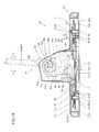
- the plate member 71 so moves along arrow P that the rack gear 73 also moves along arrow P following the plate member 71, as shown in Fig. 19 .
- the rotating gear 83 meshing with the rack gear 73 is rotated along arrow C while maintaining the meshing state. Consequently, the display screen support member 81 is turned upward (along arrow C) at a prescribed rotational frequency.
- the driving gear 61 is brought into pressure contact with the driven gear 62 by the coil spring 63 with the previously set urging force.
- driving torque exceeding the frictional force between the engaging portion 61l of the driving gear 61 and the outer peripheral surfaces 62e of the fragment portions 62b of the driven gear 62 following the pressure contact force of the coil spring 63 is generated with respect to the driving gear 61, therefore, the engaging portion 611 of the driving gear 61 and the outer peripheral surfaces 62e of the fragment portions 62b of the driven gear 62 so slip that the driving torque of the driving gear 61 is not transmitted to the driven gear 62.
- the rotation of the driven gear 62 is stopped regardless of the rotation of the driving gear 61.
- the display screen support member 81 is rotated around the upper surfaces 82f of the support shafts 82d serving as rotation centers while the base portions 81g of the sectorial holes 81f of the display screen support member 81 and the upper surfaces 82f of the support shafts 82d of the vertical support members 82 are in contact with each other.
- the driving torque is not transmitted to the driven gear 62, the gears 54 and 55 and the rack gear 72 subsequent to the driving gear 61 of the torque limiter 60.
- the rotation is stopped regardless of the driving of the stepping motor 52.
- the driving torque is not transmitted to the driven gear 62, the gears 44 and 45 and the turning gear member 48 subsequent to the driving gear 61 of the torque limiter 60.
- the turntable 31 comes into contact with the stopper member (not shown), therefore, the rotation is stopped regardless of the driving of the stepping motor 42.
- the driving gear 61 is fitted with the driven gear 62 by bringing the plurality of fragment portions 62b of the driven gear 62 into pressure contact with the fit portion 61k of the driving gear 61 having the lid portion 61b arranged to cover the spring storage portion 62d into which the coil spring 63 is press-fitted, whereby the driving gear 61 is hardly detached from the driven gear 62.
- the lid portion 61b of the driving gear 61 covers the spring storage portion 62d when the driven gear 61 is fitted with the driven gear 62, whereby the coil spring 63 can be inhibited from slipping out of the spring storage portion 62d.
- the shaft receiving portion 61d is provided with the pair of groove portions 61f and the engaging support portion 61h formed to be elastically deformable in the region held between the pair of groove portions 61f so that the engaging support portion 61h provided with the protrusion 61j can be elastically deformed by the pair of groove portions 61f, whereby the driving gear 61 can be more easily attached to and detached from the fixed shaft 37.
- the hole 61g for rendering the engaging support portion 61h deflectable is provided on the outer peripheral surface side of the engaging support portion 61h of the shaft receiving portion 61d so that the shaft receiving portion 61d can be easily deflected in the direction (along arrow U) for separating from the groove portion 37a of the fixed shaft 37, whereby the driving gear 61 can be more easily attached to and detached from the fixed shaft 37.
- the present invention is applied to the display screen turning apparatus 20 for a liquid crystal display employed as an exemplary television set in the aforementioned embodiment, the present invention is not restricted to this but is also applicable to a display screen turning apparatus for a television set having a display screen portion such as an organic EL panel other than the liquid crystal panel.
- the present invention is not restricted to this but the fragment portions 62b of the driven gear 62 may not be provided at equiangular intervals. Further, the fragment portions 62b of the driven gear 62 may be provided in a number other than eight.
- lid portion 61b of the driving gear 61 is provided over the entire upper surface of the driving gear 61 in the aforementioned embodiment, the present invention is not restricted to this but the lid portion 61b may alternatively be provided only on a part of the upper surface of the driving gear 61, so far as the same can inhibit the coil spring 63 from slipping upward (along arrow Z1 in Fig. 9 ).
Landscapes
- Engineering & Computer Science (AREA)
- General Engineering & Computer Science (AREA)
- Mechanical Engineering (AREA)
- One-Way And Automatic Clutches, And Combinations Of Different Clutches (AREA)
- Devices For Indicating Variable Information By Combining Individual Elements (AREA)
Abstract
Description
- The present invention relates to a torque limiter, a display screen turning apparatus comprising a torque limiter and a television set including a torque limiter.
- A torque limiter having a spring member is known in general, as disclosed in each of Japanese Utility Model Laying-Open No.
5-15140 (1993 6-180899 (1994 6-176444 (1994 - The aforementioned Japanese Utility Model Laying-Open No.
5-15140 5-15140 - The aforementioned Japanese Patent Laying-Open No.
6-180899 6-180899 6-180899 - The aforementioned Japanese Patent Laying-Open No.
6-176444 6-176444 - In the reel driving apparatus described in the aforementioned Japanese Utility Model Laying-Open No.
5-15140 - In the clutch structure disclosed in the aforementioned Japanese Patent Laying-Open No.
6-180899 - In the felt clutch mechanism described in the aforementioned Japanese Patent Laying-Open No.
6-176444 - The present invention has been proposed in order to solve the aforementioned problems, and an object of the present invention is to provide a torque limiter capable of transmitting bidirectional rotation while suppressing increase in the number of components.
- A torque limiter according to a first aspect of the present invention comprises a first rotating member integrally provided with a plurality of fragment portions in a concentric manner and having a spring storage portion enclosed with the plurality of fragment portions, a second rotating member having a lid portion arranged to cover the spring storage portion of the first rotating member and a fit portion fitted with the outer peripheral surfaces of the plurality of fragment portions of the first rotating member and a spring member press-fitted into the spring storage portion enclosed with the inner peripheral surfaces of the plurality of fragment portions of the first rotating member thereby bringing the plurality of fragment portions into pressure contact with the fit portion of the second rotating member, for transmitting driving torque in response to pressure contact force applied by the spring member.
- As hereinabove described, the torque limiter according to the first aspect comprises the first rotating member having the spring storage portion enclosed with the plurality of fragment portions, the second rotating member having the fit portion fitted with the outer peripheral surfaces of the plurality of fragment portions of the first rotating member and the spring member bringing the plurality of fragment portions into pressure contact with the fit portion of the second rotating member for transmitting the driving torque in response to the pressure contact force applied by the spring member, whereby the driving torque responsive to the pressure contact force applied by the spring member can be transmitted while the plurality of fragment portions of the first rotating member and the fit portion of the second rotating member are directly in surface contact with each other by the spring member. Thus, no friction member such as a felt member may be separately provided, whereby increase in the number of components can be suppressed. Further, the torque limiter is so formed as to transmit the driving torque in response to the pressure contact force applied by the spring member, whereby bidirectional rotation can be transmitted since the pressure contact force applied by the spring member has the same magnitude regardless of the direction of rotation of the first and second rotating members. In addition, the plurality of fragment portions of the first rotating member are brought into pressure contact with the fit portion of the second rotating member having the lid portion arranged to cover the spring storage portion into which the spring member is press-fitted so that the second rotating member is fitted with the first rotating member due to the pressure contact, whereby the second rotating member is hardly detached from the first rotating member. Thus, the lid portion of the second rotating member covers the spring storage portion in the state where the second rotating member is fitted with the first rotating member, whereby the spring member can be inhibited from slipping out of the spring storage portion. Dissimilarly to a case where a stop hook is provided on the spring storage portion for inhibiting the spring member from slipping out of the spring storage portion, the spring member may not be press-fitted into the spring storage portion while avoiding a hook when the first rotating member and the spring member are combined with each other, whereby the first rotating member and the spring member can be easily combined with each other.
- In the aforementioned torque limiter according to the first aspect, the first rotating member preferably further has a first shaft receiving portion at the center of the first rotating member while the second rotating member preferably further has a second shaft receiving portion provided at the center of the second rotating member to correspond to the first shaft receiving portion, and the torque limiter preferably further comprises a fixed shaft portion inserted into the first shaft receiving portion of the first rotating member and the second shaft receiving portion of the second rotating member for rotatably supporting the first rotating member and the second rotating member. According to this structure, the centers of the first and second rotating members are fixed by the fixed shaft portion dissimilarly to a case where the fixed shaft portion is not inserted into the first or second rotating member, whereby the first and second rotating members do not deviate from ordinary positions even if force is applied to the first or second rotating member from a direction other than that perpendicular to the fixed shaft portion. Thus, nontransmission of the driving torque resulting from deviation of the first or second rotating member from the ordinary position can be suppressed.
- In this case, the fixed shaft portion is preferably integrally provided with a first engaging portion, and the second shaft receiving portion is preferably integrally provided with a second engaging portion rotatably engaging with the first engaging portion of the fixed shaft portion. According to this structure, the fixed shaft portion and the second shaft receiving portion so engage with each other as to regulate movement of the second rotating member provided with the second shaft receiving portion in an extensional direction of the fixed shaft portion. The first and second rotating members are pivotally supported by the fixed shaft portion, whereby the extensional direction of the fixed shaft portion and the direction of the second rotating member fitted with the first rotating member are identical to each other. Thus, movement of the second rotating member in the direction fitted with the first rotating member is regulated due to the engagement between the second shaft receiving portion and the fixed shaft portion so that the second rotating member is more hardly detached from the first rotating member, whereby the spring member can be more inhibited from slipping out of the spring storage portion of the first rotating member due to the lid portion of the second rotating member. Further, the fixed shaft portion and the second shaft receiving portion are integrally provided with the first and second engaging portions respectively so that no member for engaging the fixed shaft portion and the second shaft receiving portion with each other may be separately provided, whereby increase in the number of components can be suppressed.
- In the aforementioned torque limiter having the second shaft receiving portion provided with the second engaging portion, the first engaging portion is preferably a groove portion peripherally provided on the outer peripheral surface of the fixed shaft portion, and the second engaging portion is preferably a protrusion engaging with the groove portion. According to this structure, the protrusion of the second rotating member can move in the groove portion peripherally provided on the outer peripheral surface of the fixed shaft portion while the second rotating member rotates with respect to the fixed shaft portion, whereby the engaging state between the first and second engaging portions can be easily maintained while rotating the second rotating member with respect to the fixed shaft portion.
- In the aforementioned torque limiter having the second engaging portion formed by the protrusion, the second shaft receiving portion is preferably formed to be elastically deformable in a direction where the protrusion separates from the groove portion of the fixed shaft portion. According to this structure, the second rotating member can be easily attached to and detached from the fixed shaft portion by elastically deforming the second shaft receiving portion so that the protrusion separates from the groove portion.
- In the aforementioned torque limiter having the second shaft receiving portion formed to be elastically deformable, the second shaft receiving portion preferably includes a pair of notches and an engaging support portion provided with the protrusion and formed to be elastically deformable in a region held between the pair of notches. According to this structure, the engaging support portion provided with the protrusion can be elastically deformed by the pair of notches, whereby the second rotating member can be more easily attached to and detached from the fixed shaft portion.
- In the aforementioned torque limiter having the second shaft receiving portion including the engaging support portion, the protrusion of the engaging support portion is preferably formed on a portion of the engaging support portion on a side in an insertion direction for the fixed shaft portion. According to this structure, the quantity of elastic deformation of the engaging support portion can be increased by forming the protrusion on the portion of the engaging support portion on the side in the insertion direction for the fixed shaft portion. Thus, the engaging support portion can be rendered easily elastically deformable in the direction where the protrusion separates from the groove portion of the fixed shaft portion, whereby the second rotating member can be more easily attached to and detached from the fixed shaft portion.
- In the aforementioned torque limiter having the second shaft receiving portion including the engaging support portion, an end portion of the engaging support portion on a side in an insertion direction for the fixed shaft portion is preferably so formed as to protrude beyond an end portion on the side in the insertion direction for the fixed shaft portion in a portion of the second shaft receiving portion other than the engaging support portion. According to this structure, a finger or the like can be easily put on the end portion of the engaging support portion, whereby the protrusion can be easily elastically deformed in the direction for separating from the groove portion of the fixed shaft portion. Thus, the second rotating member can be more easily attached to and detached from the fixed shaft portion.
- In the aforementioned torque limiter having the second shaft receiving portion including the engaging support portion, an end portion of the engaging support portion on a side in an insertion direction for the fixed shaft portion is preferably so formed as to protrude beyond a forward end portion on the side in the insertion direction for the fixed shaft portion when the fixed shaft portion is inserted into the second shaft receiving portion. According to this structure, a finger or the like can be easily put on the end portion of the engaging support portion also in the state where the fixed shaft portion is inserted into the second shaft receiving portion, whereby the protrusion can be easily elastically deformed in the direction for separating from the groove portion of the fixed shaft portion. Thus, the second rotating member can be more easily detached from the fixed shaft portion.
- In the aforementioned torque limiter having the second shaft receiving portion formed to be elastically deformable, a first chamfer is preferably formed on the outer periphery of a forward end portion on a side in an insertion direction for the fixed shaft portion. According to this structure, the protrusion comes into contact with the first chamfer of the fixed shaft portion and is moved outward along the surface of the first chamfer when the fixed shaft portion is inserted into the second shaft receiving portion, whereby the second shaft receiving portion can be easily elastically deformed outward. Thus, the protrusion of the second shaft receiving portion and the groove portion of the fixed shaft portion can smoothly engage with each other.
- In the aforementioned torque limiter having the second shaft receiving portion including the engaging support portion, a hole for rendering the engaging support portion deflectable is preferably provided on the outer peripheral surface side of the engaging support portion of the second shaft receiving portion. According to this structure, the second shaft receiving portion can be rendered easily deflectable in the direction for separating from the groove portion of the fixed shaft portion, whereby the second rotating member can be more easily attached to and detached from the fixed shaft portion.
- In the aforementioned torque limiter according to the first aspect, the first rotating member preferably integrally includes a driven gear portion, and the second rotating member preferably integrally includes a driving gear portion. According to this structure, the driving torque transmitted to the second rotating member can be easily transmitted from the first rotating member to still another rotating member by the driven gear portion and the driving gear portion.
- In the aforementioned torque limiter according to the first aspect, the fit portion of the second rotating member is preferably formed to be fitted with the outer peripheral surfaces of the plurality of fragment portions of the first rotating member from above, and a second chamfer is preferably formed on the inner peripheral surface side of the lower portion of the fit portion. The second rotating member is hardly fitted with the first rotating member having the spring storage portion storing the spring member since the spring member is so formed as to bring the plurality of fragment portions into pressure contact with the fit portion. According to this structure, however, the second chamfer is so formed that the second rotating member can be fitted with the first rotating member by sliding the upper end portions of the plurality of fragment portions on the second chamfer, whereby the second rotating member can be easily fitted with the first rotating member.
- In the aforementioned torque limiter according to the first aspect, the fit portion of the second rotating member is preferably formed to be fitted with the outer peripheral surfaces of the plurality of fragment portions of the first rotating member from above, and third chamfers are preferably formed on the outer peripheral surface sides of the upper end portions of the plurality of fragment portions. The second rotating member is hardly fitted with the first rotating member having the spring storage portion storing the spring member since the spring member is so formed as to bring the plurality of fragment portions into pressure contact with the fit portion. According to this structure, however, the third chamfers are so formed that the second rotating member can be fitted with the first rotating member by sliding the lower end portion of the fit portion on the third chamfers, whereby the second rotating member can be easily fitted with the first rotating member.
- In the aforementioned torque limiter having the first engaging portion formed by the groove portion and the second engaging portion formed by the protrusion, a surface of the protrusion of the second shaft receiving portion opposed to the bottom surface of the peripheral groove portion of the fixed shaft portion is preferably arcuately formed to correspond to the bottom surface of the peripheral groove portion of the fixed shaft portion. According to this structure, the protrusion of the second shaft receiving portion can be fitted along the bottom surface of the peripheral groove portion of the fixed shaft portion, whereby the protrusion can be more deeply fitted into the groove portion without inhibiting the rotation of the second rotating member with respect to the fixed shaft portion.
- The foregoing and other objects, features, aspects and advantages of the present invention will become more apparent from the following detailed description of the present invention when taken in conjunction with the accompanying drawings.
-
-
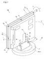
Fig. 1 is a perspective view showing the overall structure of a liquid crystal display provided with a display screen turning apparatus including a torque limiter according to an embodiment of the present invention; -
Fig. 2 is an exploded perspective view of the liquid crystal display according to the embodiment of the present invention shown inFig. 1 ; -
Fig. 3 is a plan view of the display screen turning apparatus provided with the torque limiter according to the embodiment of the present invention shown inFig. 1 ; -
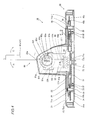
Fig. 4 is a sectional view of the display screen turning apparatus provided with the torque limiter according to the embodiment of the present invention shown inFig. 1 ; -
Fig. 5 is an exploded perspective view of the torque limiter according to the embodiment of the present invention shown inFig. 1 ; -
Fig. 6 is a sectional view around a horizontal turning/driving portion provided with the torque limiter according to the embodiment of the present invention shown inFig. 1 ; -
Fig. 7 is a sectional view around a vertical turning/driving portion provided with the torque limiter according to the embodiment of the present invention shown inFig. 1 ; -
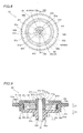
Fig. 8 is a plan view of the torque limiter according to the embodiment of the present invention shown inFig. 1 ; -
Fig. 9 is a sectional view taken along the line 200-200 inFig. 8 ; -
Fig. 10 is an exploded sectional view of the torque limiter according to the embodiment of the present invention shown inFig. 1 ; -
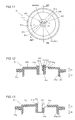
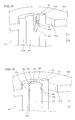
Fig. 11 is a plan view of a driving gear of the torque limiter according to the embodiment of the present invention shown inFig. 1 ; -
Fig. 12 is a sectional view taken along the line 300-300 inFig. 11 ; -
Fig. 13 is a sectional view taken along the line 400-400 inFig. 11 ; -
Fig. 14 is an enlarged view around a protrusion of the driving gear of the torque limiter according to the embodiment of the present invention shown inFig. 1 ; -
Fig. 15 is an enlarged view around the protrusion of the driving gear of the torque limiter according to the embodiment of the present invention shown inFig. 1 in a state receiving a fixed shaft; -
Fig. 16 is a plan view of a driven gear of the torque limiter according to the embodiment of the present invention shown inFig. 1 ; -
Fig. 17 is a sectional view taken along the line 500-500 inFig. 16 ; -
Fig. 18 is an enlarged view for illustrating assembling of the torque limiter and the fixed shaft according to the embodiment of the present invention shown inFig. 1 ; -
Fig. 19 is a sectional view for illustrating an upward turning operation (along arrow C) of the display screen turning apparatus according to the embodiment of the present invention shown inFig. 1 ; -
Fig. 20 is a sectional view for illustrating a downward turning operation (along arrow D) of the display screen turning apparatus according to the embodiment of the present invention shown inFig. 1 ; and -
Fig. 21 is a plan view for illustrating a leftward turning operation (along arrow A inFig. 1 ) of the display screen turning apparatus according to the embodiment of the present invention shown inFig. 1 . - An embodiment of the present invention is now described with reference to the drawings.
- First, the structures of a torque limiter and a display screen turning apparatus provided with the torque limiter according to the embodiment of the present invention are described with reference to
Figs. 1 to 17 . According to this embodiment, the present invention is applied to the display screen turning apparatus for a liquid crystal display employed as an exemplary television set. - As shown in
Fig. 1 , a displayscreen turning apparatus 20 according to the embodiment of the present invention is so provided as to enable adisplay body 10 of aliquid crystal display 100 supported by a displayscreen support mechanism 80 to turn in a horizontal direction (along arrow A or B) by a prescribed angle in a horizontal plane and to be inclined in the anteroposterior direction (along arrow C or D) by a prescribed angle with respect to a vertical plane. Thedisplay body 10 is an example of the "display screen portion" in the present invention. - As shown in
Fig. 3 , the displayscreen turning apparatus 20 is constituted of the displayscreen support mechanism 80 supporting the display body 10 (seeFig. 2 ), abase portion 30 for turning the display body 10 (seeFig. 2 ) supported by the displayscreen support mechanism 80 in the horizontal direction (along arrow A or B inFig. 1 ) in the horizontal plane, a horizontal turning/drivingportion 40 horizontally turning aturntable 31, described later, arranged on thebase portion 30 while controlling the turning angle of theturntable 31 and a vertical turning/drivingportion 50 turning thedisplay body 10 supported by the displayscreen support mechanism 80 in the anteroposterior direction (along arrow C or D inFig. 1 ) by the prescribed angle with respect to the vertical plane while controlling the turning angle of the displayscreen support mechanism 80. - As shown in
Figs. 4 and5 , thebase portion 30 includes theturntable 31 of sheet metal mounted with the displayscreen support mechanism 80, aguide member 33 of resin having a plurality ofsteel balls 32 arranged therein at prescribed intervals and rotatably holding thesteel balls 32, abase member 34 of sheet metal, a support member (not shown) of metal rotatably supporting theturntable 31 on thebase member 34,boss members 35 of resin receiving rotating shafts ofgears rack plate 70 of the vertical turning/drivingportion 50 to be reciprocative in the horizontal plane, and stopring members 36 of therack plate 70 received by theboss members 35. - The
base member 34 of thebase portion 30 is provided withgears shafts torque limiter 60, as shown inFigs. 3 and5 . The fixedshafts base member 34 to protrude upward (along arrow Z2) as shown inFig. 5 , and so formed as to have circular sections, as shown inFig. 3 . The fixedshaft 37 is an example of the "fixed shaft portion" in the present invention. - According to this embodiment, a
groove portion 37a is peripherally formed on the fixedshaft 37, as shown inFigs. 9 and10 . Thus, thegroove portion 37a is integrally provided on the fixedshaft 37. Thegroove portion 37a is so provided as to engage with aprotrusion 61j described later. Aninclined portion 37c is formed on the outer periphery of anupper end portion 37b of the fixedshaft 37 in an insertion direction (along arrow Z1) for the fixedshaft 37 by chamfering the outer periphery of theupper end portion 37b. Thegroove portion 37a is formed on the outer peripheral surface of the fixedshaft 37 in the vicinity of theupper end portion 37b. Thegroove portion 37a is an example of the "first engaging portion" in the present invention, and theupper end portion 37b is an example of the "forward end portion" in the present invention. Theinclined portion 37c is an example of the "first chamfer" in the present invention. - As shown in
Figs. 3 and5 , the horizontal turning/drivingportion 40 is constituted of atransmission gear portion 41 for rotating theturntable 31 provided on thebase portion 30 in the horizontal direction (along arrow A or B inFig. 1 ) in the horizontal plane and a steppingmotor 42 serving as a driving source for thetransmission gear portion 41. The horizontal turning/drivingportion 40 is formed to be arranged in thebase portion 30, as shown inFig. 3 . Thetransmission gear portion 41 is so formed that thegear 43 of resin, thetorque limiter 60 and thegear 44 of resin are arranged in agear box 46 of resin while thegear 45 of resin is arranged outside thegear box 46. - The
torque limiter 60 is constituted of adriving gear 61 of resin, a drivengear 62 of resin and acoil spring 63 of metal, as shown inFigs. 8 to 10 . Thedriving gear 61 and the drivengear 62 are examples of the "second rotating member" and the "first rotating member" in the present invention respectively. Thecoil spring 63 is an example of the "spring member" in the present invention. - As shown in
Fig. 11 , agear portion 61a is peripherally provided on the side surface of thedriving gear 61 of resin. Alid portion 61b concentric with thegear portion 61a is formed on thedriving gear 61 over the entire upper surface located above (along arrow Z1 inFig. 12 ) the position provided with thegear portion 61a. At the center of thedriving gear 61, ashaft receiving portion 61c provided with ashaft receiving hole 61c receiving the fixedshaft 37 is formed integrally with thedriving gear 61. When the fixedshaft 37 is inserted into theshaft receiving hole 61c, thedriving gear 61 is supported to be rotatable with respect to the fixedshaft 37. Thegear portion 61a and theshaft receiving portion 61d are examples of the "driving gear portion" and the "second shaft receiving portion" in the present invention respectively. - As shown in
Fig. 11 , theshaft receiving portion 61d is provided concentrically with thegear portion 61a. As shown inFigs. 12 and 13 , theshaft receiving portion 61d is so provided as to protrude upward (along arrow Z1) from thelid portion 61b, and to extend downward (along arrow Z2) from thelid portion 61b. As shown inFig. 9 , alower end portion 61e of theshaft receiving portion 61d is so formed as to come into contact with anupper end portion 62h of ashaft receiving portion 62g, described later, of the drivengear 62. - As shown in
Fig. 11 , an upper portion of theshaft receiving portion 61d is partially cut on two positions, to form a pair ofgroove portions 61f. Thelid portion 61b is partially cut in a sectorial manner to connect the pair ofgroove portions 61f with each other, thereby forming ahole 61g. Thus, an engagingsupport portion 61h partially forming theshaft receiving portion 61d is provided on a position enclosed with the pair ofgroove portions 61f, thehole 61g and theshaft receiving hole 61c. The engagingsupport portion 61h is provided concentrically with theshaft receiving portion 61d, so that the side surface of the fixedshaft 37 comes into contact with theshaft receiving portion 61d and the engagingsupport portion 61h when the fixedshaft 37 is inserted into theshaft receiving hole 61c of theshaft receiving portion 61d. Thehole 61g is formed to be positioned on the outer peripheral surface side (along arrow U) of the engagingsupport portion 61h. The pair ofgroove portions 61f are examples of the "notches" in the present invention respectively. - According to this embodiment, the engaging
support portion 61h, provided integrally with theshaft receiving portion 61d and thedriving gear 61 as hereinabove described, is made of elastically deformable resin. Further, the engagingsupport portion 61h is enclosed with the pair ofgroove portions 61f, thehole 61g and theshaft receiving hole 61c. Thus, the engagingsupport portion 61h is formed to be elastically deformable toward thehole 61g (along arrow U) and toward theshaft receiving hole 61c (along arrow V) with reference to a position close to the bottom surfaces of thegroove portions 61f of the engagingsupport portion 61h, as shown inFig. 11 . - An
upper end portion 61i of the engagingsupport portion 61h protrudes slightly upward (along arrow Z1) beyond the upper end portion of theshaft receiving portion 61d as shown inFig. 12 , and protrudes slightly upward (along arrow Z1) beyond theupper end portion 37b of the fixedshaft 37 when the fixedshaft 37 is inserted into theshaft receiving hole 61c, as shown inFig. 9 . - According to this embodiment, the
protrusion 61j is integrally formed in the vicinity of theupper end portion 61i of the engagingsupport portion 61h in the insertion direction (along arrow Z1) for the fixedshaft 37 to protrude toward the axial center of theshaft receiving hole 61c receiving the fixedshaft 37, as shown inFig. 14 . Theprotrusion 61j is an example of the "second engaging portion" in the present invention. Theprotrusion 61j is so formed as to engage with thegroove portion 37a of the fixedshaft 37, and formed to be movable in thegroove portion 37a following rotation of thedriving gear 61 in the state engaging with thegroove portion 37a provided on the outer peripheral surface of the fixedshaft 37 when thedriving gear 61 rotates with respect to the fixedshaft 37, as shown inFig. 15 . Thedriving gear 61 is so formed that movement in the extensional direction of the fixed shaft 37 (along arrow Z1 or Z2) is regulated when thegroove portion 37a of the fixedshaft 37 and theprotrusion 61j engage with each other. Thus, when thedriving gear 61 is fitted from above (along arrow Z1) with the drivengear 62 having thecoil spring 63 press-fitted thereinto, thedriving gear 61 is pressed from below (along arrow Z2) thereby inhibiting thecoil spring 63 from upward displacement, as sow inFig. 9 . Asurface 61k of theprotrusion 61j opposed to the bottom surface of theperipheral groove portion 37a of the fixedshaft 37 is arcuately formed to correspond to the bottom surface of theperipheral groove portion 37a of the fixedshaft 37. - As shown in
Figs. 12 and 13 , an engagingportion 611 is formed concentrically with thegear portion 61a, to extend downward (along arrow Z2) from the side surface of thelid portion 61b. The engagingportion 611 is so formed that a plurality offragment portions 62b, described later, of the drivengear 62 having thecoil spring 63 press-fitted thereinto are inserted into the inner peripheral surface side thereof to come into pressure contact with the engagingportion 611. Aninclined portion 61m is formed on the inner peripheral surface side of the lower end portion of the engagingportion 611 by chamfering the lower end portion of the engagingportion 611 along the inner peripheral surface. Theinclined portion 61m is an example of the "second chamfer" in the present invention. - As shown in
Figs. 16 and 17 , agear portion 62a is peripherally provided on the side surface of the drivengear 62 of resin. In the drivengear 62, the plurality offragment portions 62b concentric with thegear portion 62a are integrally formed on the upper surface located above (along arrow Z1 inFig. 17 ) the position provided with thegear portion 62a. Eightsuch fragment portions 62b are provided to extend upward concentrically at equiangular intervals of 45°. Thegear portion 62a is an example of the "driven gear portion" in the present invention. - According to this embodiment, a
spring receiving portion 62d into which thecoil spring 63 is press-fitted from above (along arrow Z1) is formed on the sides of innerperipheral surfaces 62c of the plurality offragment portions 62b, as shown inFig. 16 . Thecoil spring 63 is so inserted into thespring storage portion 62d as to press the plurality offragment portions 62b toward the sides of outerperipheral surfaces 62e thereof. Thus, pressure contact force is applied to the engagingportion 611 of thedriving gear 61 fitted with the sides of the outerperipheral surfaces 62e of the plurality offragment portions 62b from above (along arrow Z1), as shown inFig. 9 . The plurality offragment portions 62b are formed separately from each other, to be deformable toward the sides of the outerperipheral surfaces 62e respectively. Thus, thecoil spring 63 can be easily press-fitted into thespring storage portion 62d by deforming thefragment portions 62b toward the sides of the outerperipheral surfaces 62e respectively. When thedriving gear 61 is fitted with the drivengear 62, thelid portion 61b of thedriving gear 61 covers thespring storage portion 62d from above (along arrow Z1), as shown inFig. 9 . - As shown in
Figs. 16 and 17 , theshaft receiving portion 62g provided with ashaft receiving hole 62f receiving the fixedshaft 37 is formed at the center of the drivengear 62 of resin, integrally with the drivengear 62. Theshaft receiving hole 62g is an example of the "first shaft receiving portion" in the present invention. When the fixedshaft 37 is inserted into theshaft receiving hole 62f, the drivengear 62 is supported to be rotatable with respect to the fixedshaft 37. - As shown in
Fig. 17 , theupper end portion 62h of theshaft receiving portion 62g slightly protrudes upward (along arrow Z1) beyond thespring storage portion 62d, and most part of theshaft receiving portion 62g is so provided as to extend downward (along arrow Z2) from thespring storage portion 62d. As shown inFig. 9 , theupper end portion 62h of theshaft receiving portion 62g is so formed as to come into contact with thelower end portion 61e of theshaft receiving portion 61d of thedriving gear 61. -
Inclined portions 62i are formed on the sides of the outerperipheral surfaces 62e of the upper end portions of the plurality offragment portions 62b by chamfering the upper end portions of the plurality offragment portions 62b along the outerperipheral surfaces 62e. Theinclined portions 62i are examples of the "third chamfers" in the present invention. - According to this embodiment, the
driving gear 61 of thetorque limiter 60 is brought into pressure contact with the drivengear 62 by thecoil spring 63 with previously set urging force. When driving torque exceeding frictional force between the engagingportion 611 of thedriving gear 61 and the outerperipheral surfaces 62e of thefragment portions 62b of the drivengear 62 following the pressure contact force of thecoil spring 63 is generated with respect to thedriving gear 61, therefore, the engagingportion 611 of thedriving gear 61 and the outerperipheral surfaces 62e of thefragment portions 62b of the drivengear 62 so slip that the driving torque of thedriving gear 61 is not entirely transmitted to the drivengear 62. When driving torque below the frictional force between the engagingportion 611 of thedriving gear 61 and the outerperipheral surfaces 62e of thefragment portions 62b of the drivengear 62 following the pressure contact force of thecoil spring 63 is generated with respect to thedriving gear 61, on the other hand, the engagingportion 611 of thedriving gear 61 does not slip with respect to the outerperipheral surfaces 62e of thefragment portions 62b of the drivengear 62 but transmits the rotational frequency of thedriving gear 61 to the drivengear 62. - As shown in
Fig. 3 , aworm gear 47 of resin is press-fitted into the rotating shaft of the steppingmotor 42 of the horizontal turning/drivingportion 40. As shown inFig. 6 , thegear 43 integrally includes a large-diametral gear portion 43a and a small-diametral gear portion 43b. Thegear 44 also integrally includes a large-diametral gear portion 44a and a small-diametral gear portion 44b. Further, thegear 45 also integrally includes a large-diametral gear portion 45a and a small-diametral gear portion 45b. Aturning gear member 48 of resin is fixed to anupper surface 31a of theturntable 31 of thebase portion 30 with fourscrews 90. - As shown in
Fig. 6 , theworm gear 47 meshes with the large-diametral gear portion 43a of thegear 43 so that the rotating shaft thereof is orthogonal thereto, while the small-diametral gear portion 43b of thegear 43 meshes with thegear portion 61a of thedriving gear 61 of thetorque limiter 60. Thegear portion 62a of the drivengear 62 of thetorque limiter 60 meshes with the large-diametral gear portion 44a of thegear 44, while the small-diametral gear portion 44b of thegear 44 meshes with the large-diametral gear portion 45a of thegear 45. The small-diametral gear portion 45b of thegear 45 meshes with theturning gear portion 48a of theturning gear member 48. Therefore, driving force of the steppingmotor 42 is transmitted to theturntable 31 through theworm gear 47, thegear 43, thetorque limiter 60, thegears turning gear member 48. - As shown in
Figs. 3 and5 , the vertical turning/drivingportion 50 is constituted of atransmission gear portion 51 consisting of a plurality of gear members, a steppingmotor 52 serving as a driving source for thetransmission gear portion 51 and therack plate 70 for rotating a displayscreen support member 81 rotatably provided on the displayscreen support mechanism 80 mounted on theturntable 31 of thebase portion 30 in the anteroposterior direction (along arrow C or D inFig. 1 ) with respect to the vertical plane. - As shown in
Fig. 3 , thetransmission gear portion 51 is so formed that thegear 53 of resin, thetorque limiter 60 and thegear 54 of resin are arranged in agear box 56 of resin while thegear 55 of resin is arranged outside thegear box 56. As shown inFig. 7 , thegear 53 of resin integrally includes a large-diametral gear portion 53a and a small-diametral gear portion 53b. Thegear 54 of resin also integrally includes a large-diametral gear portion 54a and a small-diametral gear portion 54b. Further, thegear 55 of resin also integrally includes a large-diametral gear portion 55a and a small-diametral gear portion 55b. - As shown in
Fig. 7 , aworm gear 57 of resin is press-fitted into the rotating shaft of the steppingmotor 52. Theworm gear 57 meshes with the large-diametral gear portion 53a of thegear 53 so that the rotating shaft is orthogonal thereto. The small-diametral gear portion 53b of thegear 53 meshes with thegear portion 61a of thedriving gear 61 of thetorque limiter 60. Thegear portion 62a of the drivengear 62 of thetorque limiter 60 meshes with the large-diametral gear portion 54a of thegear 54, while the small-diametral gear portion 54b of thegear 54 meshes with the large-diametral gear portion 55a of thegear 55. The small-diametral gear portion 55b of thegear 55 horizontally meshes with agear portion 72a of arack gear 72 described later. Therefore, driving force of the steppingmotor 52 is transmitted to therack plate 70 through theworm gear 57, thegear 53, thetorque limiter 60, thegears rack gear 72. - The
rack plate 70 is constituted of aplate member 71 of sheet metal, therack gear 72 of resin and anotherrack gear 73 of resin, as shown inFig. 5 . Therack gear 72 is mounted on the lower surface of theplate member 71 with ascrew 90. Therack gear 72 is so formed as to horizontally mesh with the small-diametral gear portion 55 of thegear 55, as shown inFig. 3 . - As shown in
Fig. 5 ,slots plate member 71 are formed in the vicinity of both longitudinal end portions of theplate member 71 respectively, while acircular receiving hole 71c receiving aprotrusion 73a of therack gear 73 is formed on a substantially central portion of theplate member 71. Theplate member 71 further has twopositioning holes 71d and ascrew mounting hole 71e. - As shown in
Fig. 5 , therack gear 72 is provided with thegear portion 72a along the longitudinal side surface along arrow Y1, and also provided with twobosses 72b and ascrew receiving hole 72c. Therefore, therack gear 72 can be mounted on theplate member 71 from below (along arrow Z2) by fitting thebosses 72b of therack gear 72 into thepositioning holes 71d of theplate member 71 and tightening thescrew 90 into thescrew mounting hole 71e of theplate member 71 through thescrew receiving hole 72c of therack gear 72. - A
tooth flank 73b having a plurality of tooth tips is formed on a surface of therack gear 73 along arrow Z1 arranged on theplate member 71 in the form of a planar surface, as shown inFig. 5 . The ring-shapedprotrusion 73a insertable into the receivinghole 71c of theplate member 71 is formed on a substantially central portion of arear surface 73c of therack gear 73 along arrow Z2. Thus, when theprotrusion 73a is inserted into the receivinghole 71c of theplate member 71, thetooth flank 73b is horizontalized (planarized), and rotatable along arrow H1 or H2 (seeFig. 3 ) with respect to theplate member 71. - When the pair of
boss members 35 are inserted into therack plate 70 through theslots plate member 71 respectively, therack plate 70 is linearly reciprocative along arrows P and Q, as shown inFigs. 3 and4 . Therefore, normal or reverse rotation of the steppingmotor 52 is so transmitted to therack gear 72 through thetransmission gear portion 51 that therack plate 70 is linearly reciprocative on theturntable 31 along arrows P and Q. - The display
screen support mechanism 80 is constituted of the displayscreen support member 81 made of sheet metal, a pair ofvertical support members 82 of sheet metal and arotating gear 83 of resin so arranged as to mesh with therack gear 73 of therack plate 70, as shown inFig. 5 . The displayscreen support member 81 is mounted on the pair ofvertical support members 82 to be rotatable with torque exceeding a prescribed level. - The display
screen support member 81 includes a pair of displaybody mounting portions 81a so provided as to extend upward (along arrow Z1) and a pair ofrotating portions 81b provided on side surfaces of the displayscreen support member 81 along arrows Y1 and Y2 respectively, as shown inFig. 5 . Screw receivingholes 81c are formed in the pair of displaybody mounting portions 81a respectively. - The pair of
rotating portions 81b of the displayscreen support member 81 are provided to extend from both end portions of the displaybody mounting portions 81a in the vertical direction (along arrows X1 and X2) with respect to the displaybody mounting portions 81a respectively.Notches 81d concaved along arrow X2 are formed on therotating portions 81b along arrow X1, whileprotrusions 81e convexed along arrow X2 are formed on therotating portions 81b along arrow X2. - As shown in
Figs. 4 and5 ,sectorial holes 81f are formed on therotating portions 81b. Theholes 81f are so provided as to receivesupport shafts 82d described later. Thesectorial holes 81f are so arranged thatbase portions 81g on the sides of circle centers are positioned upward, while thebase portions 81g on the sides of the circle centers come into contact withupper surfaces 82f, described later, of thesupport shafts 82d. Thus, thebase portions 81g of thesectorial holes 81f are so formed as to receive the vertical load of the display body 10 (seeFig. 2 ) through the displayscreen support member 81. The displayscreen support member 81 is formed to be rotatable in a sectorial angular range with respect to thesupport shafts 82d around thebase portions 81g of thesectorial holes 81f supported by thesupport shafts 82d in the form of flat plates. - As shown in
Fig. 5 , abody portion 81h so provided as to extend downward (along arrow Z2) from the displaybody mounting portions 81a is integrally formed on the displayscreen support member 81. Alower surface portion 81i so provided as to extend in the vertical direction (along arrows X1 and X2) with respect to thebody portion 81h is integrally formed on the lower end of thebody portion 81h. Ascrew receiving hole 81j receiving ascrew 90 for fixing therotating gear 83 and the displayscreen support member 81 to each other is formed at the center of thelower surface portion 81i. A pair ofboss receiving holes 81k are formed to hold thescrew receiving hole 81j therebetween. A pair ofbosses 83a, described later, of therotating gear 83 are inserted into the pair ofboss receiving holes 81k respectively. - The pair of
vertical support members 82 are so arranged that thesupport shafts 82d described later are inserted into theholes 81f of the displayscreen support member 81 outward from the inner side of the displayscreen support member 81 respectively, as shown inFig. 5 . More specifically, thevertical support member 82 mounted on therotating portion 81b of the displayscreen support member 81 provided along arrow Y1 is arranged to be in contact with a surface, provided along arrow Y2, of therotating portion 81b provided along arrow Y1. On the other hand, thevertical support member 82 mounted on therotating portion 81b of the displayscreen support member 81 provided along arrow Y2 is arranged to be in contact with a surface, provided along arrow Y1, of therotating portion 81b provided along arrow Y2. - The
vertical support members 82 includeturntable mounting portions 82a and rotatingportion mounting portions 82b, as shown inFig. 5 . Screw mountingholes 82c for fixing theturntable mounting portions 82a to theturntable 31 are formed on theturntable mounting portions 82a. The rotatingportion mounting portions 82b of thevertical support members 82 are so provided as to extend upward (along arrow Z1) in the vertical direction with respect to theturntable mounting portions 82a from end portions of theturntable mounting portions 82a. - As shown in
Fig. 4 , thesupport shafts 82d are formed on substantially central portions of thevertical support members 82 along arrows X1 and X2. Thesupport shafts 82d are in the form of flat plates elongated in the vertical direction (along arrows Z1 and Z2). Thesupport shafts 82d are formed integrally with thevertical support members 82 by partially uprighting thevertical support members 82 made of sheet metal.Holes 82e are formed in the uprighted portions of thevertical support members 82. - The
support shafts 82d are provided to be inserted into thesectorial holes 81f of therotating portions 81b, as shown inFigs. 4 and5 . More specifically, thesupport shafts 82d are so formed that theupper surfaces 82f thereof are in contact with thebase portions 81g of thesectorial holes 81f, as shown inFig. 4 . Thus, thesupport shafts 82d are so formed as to receive the vertical load of the display body 10 (seeFig. 2 ) on theupper surfaces 82f through thebase portions 81g of thesectorial holes 81f and the displayscreen support member 81. Further, the displayscreen support member 81 is formed to be rotatable in the angular range of thesectorial holes 81f with respect to thesupport shafts 82d around thebase portions 81g of thesectorial holes 81f supported by thesupport shafts 82d in the form of flat plates. In other words, thesupport shafts 82d function as the rotating shafts of the displayscreen support member 81. Thus, the displayscreen support member 81 renders thedisplay body 10 rotatable in the anteroposterior direction (along arrow C or D) with respect to the vertical plane of the displayscreen turning apparatus 20. - As shown in
Fig. 4 , hooks 82g are formed on first side surfaces of the rotatingportion mounting portions 82b integrally with thevertical support members 82, whilehooks 82h are formed on second side surfaces integrally with thevertical support members 82. Thehooks vertical support members 82 made of sheet metal. Thehooks support shafts 82d from slipping out of theholes 81f, thereby inhibiting thevertical support members 82 from slipping out of the displayscreen support member 81. - When rotating in excess of the rotational range of the display
screen support member 81 in the anteroposterior direction (along arrow C or D inFig. 1 ) with respect to the vertical plane in use of the displayscreen turning apparatus 20, thehooks 82g of thevertical support members 82 are separable from thenotches 81d of therotating portions 81b of the displayscreen support member 81, while thehooks 82h of thevertical support members 82 are movable in separating directions without being hindered by theprotrusions 81e of therotating portions 81b. Thus, when rotating in excess of the rotational range of the displayscreen support member 81 with respect to the vertical plane in use of the displayscreen turning apparatus 20, thevertical support members 82 are released from states stopped to the displayscreen support member 81. - As shown in
Fig. 4 , ring-shapedprotrusions 82i are formed on the rotatingportion mounting portions 82b around substantially central portions of thesupport shafts 82d. Theprotrusions 82i are formed to be in contact with therotating portions 81b of the displayscreen support member 81 when thesupport shafts 82d of the rotatingportion mounting portions 82b are inserted into theholes 81f of the displayscreen support member 81. - The
rotating gear 83 is so arranged as to mesh with therack gear 73 of therack plate 70 from above, and arranged on a substantially central portion of thelower surface portion 81i of the displayscreen support member 81, as shown inFig. 5 . Further, therack gear 73 and therotating gear 83 are positioned on the horizontal rotation centers (along arrows G1 and G2 inFig. 3 ) of theturntable 31 and the displayscreen support member 81. The pair ofbosses 83a inserted into the pair ofboss receiving holes 81k of the displayscreen support member 81 are formed on the upper surface of therotating gear 83. A threaded hole (not shown) meshing with thescrew 90 is formed at the center between the pair ofbosses 83a. The threaded hole is so formed as to correspond to thescrew receiving hole 81j of the displayscreen support member 81. - As shown in
Fig. 4 , a tooth flank is formed on the lower surface of therotating gear 83 to have an arcuate shape. Thus, therotating gear 83 is slidable with respect to therack gear 73 in a direction perpendicular to a meshing direction (along arrows S and T inFig. 3 ) of therack gear 73 and therotating gear 83 in the horizontal plane. The upper surface of therotating gear 83 is fixed to thelower surface portion 81i of the displayscreen support member 81 with thescrew 90. Thus, therotating gear 83 is fixed to the displayscreen support member 81, so that the rotation of the displayscreen support member 81 in the horizontal plane is transmitted to therack gear 73 meshing with therotating gear 83 through therotating gear 83. - As shown in
Fig. 5 , theturntable 31 of thebase portion 30 includes fourscrew receiving holes 31b provided on theupper surface 31a and ahole 31c provided at the center of theupper surface 31a (in the vicinity of the rotation center of the turntable 31). As shown inFig. 3 , theturntable 31 is arranged on a substantially central portion of thebase member 34, to be rotatable in the horizontal plane. As shown inFig. 5 , a plurality of support members (not shown) provided on thebase member 34 to circularly enclose theturntable 31 come into surface contact with outerperipheral surfaces turntable 31 and theguide member 33, thereby holding theturntable 31 to be rotatable in the horizontal plane. - As shown in
Figs. 1 and2 , thedisplay body 10 is constituted of afront cabinet 11 of resin and arear cabinet 12 of resin. Thedisplay body 10 is mounted on the displayscreen support member 81 by tighteningscrews 90 into screw receiving holes (not shown) of therear cabinet 12 through thescrew receiving holes 81c (seeFig. 5 ) of the displayscreen support member 81. Anotch 12a for concealedly arranging the displayscreen support member 81 is integrally provided on therear cabinet 12. A plurality ofscrew receiving holes 12b are provided on the outer peripheral portion of therear cabinet 12, so that therear cabinet 12 is mounted on thefront cabinet 11 withscrews 91. - In the display
screen turning apparatus 20, acover member 21 of resin is mounted on thebase member 34 with a screw (not shown) inserted from the side of the lower surface of thebase member 34 of thebase portion 30, as shown inFig. 4 . Further, anothercover member 22 of resin is mounted on theupper surface 31a of theturntable 31 with a screw (not shown) to cover thebase portion 30 from above and to be turnable in the horizontal direction (along arrow A or B inFig. 1 ) integrally with theturntable 31 of thebase portion 30, as shown inFigs. 1 and4 . Thecover member 22 of resin is provided with anotch 22a for arranging the displayscreen support member 81 to be rotatable in the anteroposterior direction (along arrow C or D inFig. 1 ), as shown inFigs. 2 and4 . - Assembling of the
torque limiter 60 according to the embodiment of the present invention and combination of thetorque limiter 60 and the fixedshaft 37 are now described with reference toFigs. 9 ,10 ,15 and18 . - As shown in
Fig. 10 , thecoil spring 63 is press-fitted into thespring receiving portion 62d of the drivengear 62 from above (along arrow Z1). Then, the engagingportion 611 of thedriving gear 61 is fitted with the outerperipheral surfaces 62e of the plurality offragment portions 62b of the drivengear 62 combined with thecoil spring 63 from above. Thus, the plurality offragment portions 62b and the engaging portion 61l are brought into pressure contact with each other, to assemble thetorque limiter 60. - As shown in
Fig. 10 , thetorque limiter 60 is set on the fixedshaft 37 from above (along arrow Z1). More specifically, the fixedshaft 37 passes through theshaft receiving hole 62f of theshaft receiving portion 62g of the drivengear 62 provided on the lower portion of thetorque limiter 60, and is inserted into theshaft receiving hole 61c of theshaft receiving portion 61d of thedriving gear 61 provided on the upper portion of thetorque limiter 60. - According to this embodiment, the
protrusion 61j of thedriving gear 61 is so provided as to protrude toward the axial center of theshaft receiving hole 61c, whereby theupper end portion 37b of the fixedshaft 37 inserted into theshaft receiving hole 61c comes into contact with theprotrusion 61j. At this time, force is applied to theupper end portion 61i of the engagingsupport portion 61h toward thehole 61g (along arrow U), thereby elastically deforming the engagingsupport portion 61h toward thehole 61g. Consequently, the fixedshaft 37 is inserted into theshaft receiving hole 61c over theprotrusion 61j. - When the fixed
shaft 37 is inserted up to a position where thegroove portion 37a thereof corresponds to theprotrusion 61j of thedriving gear portion 61, the force applied to theupper end portion 61i of the engagingsupport portion 61h is canceled. Thus, thegroove portion 37a of the fixedshaft 37 and theprotrusion 61j of thedriving gear portion 61 engage with each other as shown inFig. 15 , so that thetorque limiter 60 and the fixedshaft 37 are combined with each other as shown inFig. 9 . - Anteroposterior and horizontal turning operations of the display
screen turning apparatus 20 according to the embodiment of the present invention are now described with reference toFigs. 1 ,3 to 5 and19 to 21 . - When the display
screen turning apparatus 20 rotates the displayscreen support mechanism 80 in the anteroposterior direction (along arrow C or D) with respect to the vertical plane as shown inFig. 4 , thedisplay body 10 shown inFig. 1 is rotated upward or downward, and hence the anteroposterior direction is hereinafter referred to as an upward direction or a downward direction. - First, upward and downward turning operations (along arrows C and D in
Fig. 1 ) of the displayscreen turning apparatus 20 are described. - First, the user presses an upward tilt button (not shown) of an attached remote control (not shown), thereby transmitting a signal for turning the display body 10 (see
Fig. 1 ) in the upward direction (along arrow C inFig. 1 ) to a control circuit portion (not shown) of thedisplay body 10. The steppingmotor 52 of the displayscreen turning apparatus 20 is driven on the basis of this signal. More specifically, the steppingmotor 52 is driven to rotate theworm gear 57 mounted thereon and to rotate thedriving gear 61 of thetorque limiter 60 along arrow E1 through thegear 53, as shown inFig. 3 . The drivengear 62 of thetorque limiter 60 is also rotated along arrow E1, and thegear 55 is rotated along arrow E2 through thegear 54. Following this rotation of thegear 55 along arrow E2, theplate member 71 of therack plate 70 moves along arrow P with therack gear 72 horizontally meshing with thegear 55. - The
plate member 71 so moves along arrow P that therack gear 73 also moves along arrow P following theplate member 71, as shown inFig. 19 . Thus, when therack gear 73 moves along arrow S, therotating gear 83 meshing with therack gear 73 is rotated along arrow C while maintaining the meshing state. Consequently, the displayscreen support member 81 is turned upward (along arrow C) at a prescribed rotational frequency. At this time, the displayscreen support member 81 is rotated around theupper surfaces 82f of thesupport shafts 82d serving as rotation centers while thebase portions 81g of thesectorial holes 81f of the displayscreen support member 81 and theupper surfaces 82f of thesupport shafts 82d of thevertical support members 82 are in contact with each other. - When turning the display body 10 (see
Fig. 1 ) along arrow C up to a desired angle, the user releases the upward tilt button (not shown) of the attached remote control (not shown), so that the signal for turning thedisplay body 10 upward (along arrow C) is not transmitted to the control circuit portion (not shown) of thedisplay body 10 and the driving of the steppingmotor 52 is stopped. Thus, the displayscreen support member 81 stops turning along arrow C and stands still. - When the user continuously turns the display body 10 (see
Fig. 1 ) upward (along arrow C), first end portions of the inner side surfaces of theslots plate member 71 come into contact with the side surfaces of theboss members 35 respectively thereby regulating sliding of therack plate 70 along arrow P, as shown inFig. 19 . Therefore, thedisplay body 10 stops turning along arrow C and stands still. At this time, the steppingmotor 52 is continuously driven, and hence the driving torque transmitted from the steppingmotor 52 is transmitted to thedriving gear 61 of thetorque limiter 60 through theworm gear 57 and thegear 53. - According to this embodiment, the
driving gear 61 is brought into pressure contact with the drivengear 62 by thecoil spring 63 with the previously set urging force. When driving torque exceeding the frictional force between the engaging portion 61l of thedriving gear 61 and the outerperipheral surfaces 62e of thefragment portions 62b of the drivengear 62 following the pressure contact force of thecoil spring 63 is generated with respect to thedriving gear 61, therefore, the engagingportion 611 of thedriving gear 61 and the outerperipheral surfaces 62e of thefragment portions 62b of the drivengear 62 so slip that the driving torque of thedriving gear 61 is not transmitted to the drivengear 62. In other words, the rotation of the drivengear 62 is stopped regardless of the rotation of thedriving gear 61. Thus, the driving torque is not transmitted to the drivengear 62, thegears rack gear 72 subsequent to thedriving gear 61 of thetorque limiter 60. When the movement (sliding) of therack plate 70 along arrow P is stopped, therefore, the rotation is stopped regardless of the driving of the steppingmotor 52. - On the other hand, the user presses a downward tilt button (not shown) of the attached remote control (not shown), thereby transmitting a signal for turning the display body 10 (see
Fig. 1 ) downward (along arrow D inFig. 1 ) to the control circuit portion (not shown) of thedisplay body 10 and driving the steppingmotor 52 of the displayscreen turning apparatus 20. Thus, theworm gear 57 mounted on the steppingmotor 52 is rotated, and thedriving gear 61 of thetorque limiter 60 is rotated along arrow F1 through thegear 53, as shown inFig. 3 . The drivengear 62 of thetorque limiter 60 is rotated along arrow F1, and thegear 55 is rotated along arrow F2 through thegear 54. Therack plate 70 moves along arrow Q with therack gear 72. - The
plate member 71 so moves along arrow Q that therack gear 73 also moves along arrow T following theplate member 71, as shown inFig. 20 . Thus, when therack gear 73 moves along arrow T, therotating gear 83 meshing with therack gear 73 is rotated along arrow D while maintaining the meshing state. Consequently, the displayscreen support member 81 is turned downward (along arrow D) at the prescribed rotational frequency. At this time, the displayscreen support member 81 is rotated around theupper surfaces 82f of thesupport shafts 82d serving as rotation centers while thebase portions 81g of thesectorial holes 81f of the displayscreen support member 81 and theupper surfaces 82f of thesupport shafts 82d of thevertical support members 82 are in contact with each other. - When turning the display body 10 (see
Fig. 1 ) along arrow D up to a desired angle, the user releases the downward tilt button (not shown) of the attached remote control (not shown), so that the signal for turning thedisplay body 10 downward (along arrow D) is not transmitted to the control circuit portion (not shown) of thedisplay body 10 and the driving of the steppingmotor 52 is stopped. Thus, the displayscreen support member 81 stops turning along arrow D and stands still. - When the user continuously turns the display body 10 (see
Fig. 1 ) downward (along arrow D), second end portions of the inner side surfaces of theslots plate member 71 come into contact with the side surfaces of theboss members 35 respectively thereby regulating sliding of therack plate 70 along arrow Q, as shown inFig. 20 . Therefore, thedisplay body 10 stops turning along arrow D and stands still. - While the stepping motor 52 (see
Fig. 3 ) is continuously driven at this time, the engaging portion 61l of thedriving gear 61 and the outer peripheral surfaces of thefragment portions 62b of the drivengear 62 slip when driving torque exceeding the frictional force between the engagingportion 611 of thedriving gear 61 and the outerperipheral surfaces 62e of thefragment portions 62b of the drivengear 62 following the pressure contact force of thecoil spring 63 is generated with respect to thedriving gear 61, so that the driving torque of thedriving gear 61 is not transmitted to the drivengear 62. In other words, the rotation of the drivengear 62 is stopped regardless of the rotation of thedriving gear 61. Thus, the driving torque is not transmitted to the drivengear 62, thegears rack gear 72 subsequent to thedriving gear 61 of thetorque limiter 60. When the movement (sliding) of therack plate 70 along arrow Q is stopped, therefore, the rotation is stopped regardless of the driving of the steppingmotor 52. - The horizontal turning operation of the display
screen turning apparatus 20 in the horizontal plane is now described. - First, the user presses a horizontal turn button (not shown) of the attached remote control (not shown), thereby transmitting a signal for turning the display body 10 (see
Fig. 1 ) leftward (along arrow A inFig. 1 ) to the control circuit portion (not shown) of thedisplay body 10 and driving the steppingmotor 42 of the displayscreen turning apparatus 20. More specifically, theworm gear 47 mounted on the steppingmotor 42 is rotated following the driving of the steppingmotor 42 and thedriving gear 61 of thetorque limiter 60 is rotated along arrow E3 through thegear 43, as shown inFig. 3 . The drivengear 62 of thetorque limiter 60 is rotated along arrow E3, and theturning gear member 48 is rotated along arrow E4 through thegears turntable 31 provided on thebase portion 30 mounted with the displayscreen support member 81 turns along arrow G1, thereby turning thedisplay body 10 leftward (along arrow A inFig. 1 ) at a prescribed rotational speed. At this time, therotating gear 83 fixed to the displayscreen support member 81 is also rotated along arrow H1 following the turning of the displayscreen support member 81. Further, the rack gear 73 (seeFig. 4 ) so arranged as to mesh with therotating gear 83 is also rotated following the rotation of therotating gear 83 while maintaining the meshing state. - When turning the display body 10 (see
Fig. 1 ) up to a desired angle, the user releases the horizontal turn button (not shown) of the attached remote control (not shown), so that the signal for turning thedisplay body 10 leftward (along arrow A inFig. 1 ) is not transmitted to the control circuit portion (not shown) of thedisplay body 10 and the driving of the steppingmotor 42 is stopped. Thus, thebase portion 30 stops turning along arrow G1 and stands still, as shown inFig. 21 . - When the turning angle of the
base portion 30 reaches the maximum (30° in this embodiment) while the user continuously turns the display body 10 (seeFig. 1 ) leftward (along arrow A inFig. 1 ), theturntable 31 comes into contact with a stopper member (not shown) provided in thebase portion 30, so that the leftward turning (along arrow A inFig. 1 ) is regulated. Therefore, thebase portion 30 stops turning along arrow G1 and stands still. - While the stepping
motor 42 is continuously driven at this time, the engaging portion 61l of thedriving gear 61 and the outer peripheral surfaces of thefragment portions 62b of the drivengear 62 slip when driving torque exceeding the frictional force between the engaging portion 61l of thedriving gear 61 and the outerperipheral surfaces 62e of thefragment portions 62b of the drivengear 62 following the pressure contact force of thecoil spring 63 is generated with respect to thedriving gear 61, so that the driving torque of thedriving gear 61 is not transmitted to the drivengear 62. In other words, the rotation of the drivengear 62 is stopped regardless of the rotation of thedriving gear 61. Thus, the driving torque is not transmitted to the drivengear 62, thegears turning gear member 48 subsequent to thedriving gear 61 of thetorque limiter 60. When theturntable 31 comes into contact with the stopper member (not shown), therefore, the rotation is stopped regardless of the driving of the steppingmotor 42. - While the above turning operation has been described with reference to the case of turning the
base portion 30 along arrow G1 inFig. 3 , the horizontal turning/drivingportion 40 performs a turning operation similar to the above also in a case of oppositely turning theturntable 31 along arrow G2. Therefore, the display body 10 (seeFig. 1 ) can be turned rightward (along arrow B inFig. 1 ) by turning theturntable 31 along arrow G2. - According to this embodiment, as hereinabove described, the display
screen turning apparatus 20 comprises the drivengear 62 having thespring storage portion 62d enclosed with the plurality offragment portions 62b, thedriving gear 61 having thefit portion 61k fitted with the outerperipheral surfaces 62e of the plurality offragment portions 62b of the drivengear 62 and thecoil spring 63 bringing the plurality offragment portions 62b into pressure contact with thefit portion 61k of thedriving gear 61 for transmitting the driving torque in response to the pressure contact force applied by thecoil spring 63, whereby the driving torque responsive to the pressure contact force applied by thecoil spring 63 can be transmitted while the plurality offragment portions 62b of the drivengear 62 an thefit portion 61k of thedriving gear 61 are directly in surface contact with each other due to thecoil spring 63. Thus, no frictional member such as a felt member may be separately provided, whereby increase in the number of components can be suppressed. Further, the driving torque is so transmitted in response to the pressure contact force applied by thecoil spring 63 that the pressure contact force applied by thecoil spring 63 has the same magnitude regardless of the direction of rotation of thedriving gear 61 and the drivengear 62, whereby bidirectional rotation can be transmitted. - According to this embodiment, the
driving gear 61 is fitted with the drivengear 62 by bringing the plurality offragment portions 62b of the drivengear 62 into pressure contact with thefit portion 61k of thedriving gear 61 having thelid portion 61b arranged to cover thespring storage portion 62d into which thecoil spring 63 is press-fitted, whereby thedriving gear 61 is hardly detached from the drivengear 62. Thus, thelid portion 61b of thedriving gear 61 covers thespring storage portion 62d when the drivengear 61 is fitted with the drivengear 62, whereby thecoil spring 63 can be inhibited from slipping out of thespring storage portion 62d. Dissimilarly to a case where a stop hook is provided on thespring storage portion 62d for inhibiting thecoil spring 63 from slipping out of thespring storage portion 62d, thecoil spring 63 may not be press-fitted into thespring storage portion 62d while avoiding a hook when the drivengear 62 and thecoil spring 63 are combined with each other, whereby the drivengear 62 and thecoil spring 63 can be easily combined with each other. - According to this embodiment, the driven
gear 62 has theshaft receiving portion 62g at the center thereof, thedriving gear 61 has theshaft receiving portion 61d provided at the center thereof to correspond to theshaft receiving portion 62g, and the displayscreen turning apparatus 20 comprises the fixedshaft 37 inserted into theshaft receiving portions gear 62 and thedriving gear 61 for rotatably supporting the drivengear 62 and thedriving gear 61 so that the centers of the drivengear 62 and thedriving gear 61 are fixed by the fixedshaft 37 dissimilarly to a case where the fixedshaft 37 is not inserted into the drivengear 62 or thedriving gear 61, whereby the drivengear 62 and thedriving gear 61 do not deviate from ordinary positions even if force is applied to the drivengear 62 or thedriving gear 61 from a direction other than that perpendicular to the fixedshaft 37. Thus, nontransmission of the driving torque resulting from deviation of the drivengear 62 or thedriving gear 61 from the ordinary position can be suppressed. - According to this embodiment, the fixed
shaft 37 is provided with thegroove portion 37a peripherally formed on the outerperipheral surface 62e thereof and theshaft receiving portion 61d is integrally provided with theprotrusion 61j, so that the fixedshaft 37 and theshaft receiving portion 61d engage with each other thereby regulating movement of thedriving gear 61 provided with theshaft receiving portion 61d in the extensional direction (along arrows Z1 and Z2 inFig. 9 ) of the fixedshaft 37. The drivengear 62 and thedriving gear 61 are pivotally supported by the fixedshaft 37, whereby the extensional direction of the fixedshaft 37 and the direction for fitting thedriving gear 61 with the drivengear 62 are identical to each other. Thus, movement of thedriving gear 61 in the direction fitted with the drivengear 62 is regulated due to the engagement between theshaft receiving portion 61d and the fixedshaft 37 so that thedriving gear 61 is more hardly detached from the drivengear 62, whereby thecoil spring 63 can be more inhibited from slipping out of thespring storage portion 62d of the drivengear 62 due to thelid portion 61b of thedriving gear 61. Further, the fixedshaft 37 and theshaft receiving portion 61d are integrally provided with thegroove portion 37a and theprotrusion 61j respectively so that no member for engaging the fixedshaft 37 and theshaft receiving portion 61d with each other may be separately provided, whereby increase in the number of components can be suppressed. - According to this embodiment, the
shaft receiving portion 61d is provided with theprotrusion 61j rotatably engaging with thegroove portion 37a of the fixedshaft 37 so that theprotrusion 61j of thedriving gear 61 can move in thegroove portion 37a peripherally formed on the outerperipheral surfaces 62e of the fixedshaft 37 while thedriving gear 61 is rotated with respect to the fixedshaft 37, whereby the engaging state between thegroove portion 37a and theprotrusion 61j can be easily maintained while rotating thedriving gear 61 with respect to the fixedshaft 37. - According to this embodiment, the engaging
support portion 61h of theshaft receiving portion 61d is formed to be elastically deformable in the direction (along arrow U inFig. 11 ) where theprotrusion 61j separates from thegroove portion 37a of the fixedshaft 37, whereby thedriving gear 61 can be easily attached to and detached from the fixedshaft 37 by elastically deforming the engagingsupport portion 61 so that theprotrusion 61j separates from thegroove portion 37a. - According to this embodiment, the
shaft receiving portion 61d is provided with the pair ofgroove portions 61f and the engagingsupport portion 61h formed to be elastically deformable in the region held between the pair ofgroove portions 61f so that the engagingsupport portion 61h provided with theprotrusion 61j can be elastically deformed by the pair ofgroove portions 61f, whereby thedriving gear 61 can be more easily attached to and detached from the fixedshaft 37. - According to this embodiment, the
protrusion 61j of the engagingsupport portion 61h is formed in the vicinity of theupper end portion 61i of the engagingsupport portion 61h in the insertion direction (along arrow Z1) for the fixedshaft 37, whereby the quantity of elastic deformation of the engagingsupport portion 61h can be increased. Thus, the engagingsupport portion 61h is easily elastically deformable in the direction (along arrow U) for separating from thegroove portion 37a of the fixedshaft 37, whereby thedriving gear 61 can be more easily attached to and detached from the fixedshaft 37. - According to this embodiment, the
upper end portion 61i of the engagingsupport portion 61h is so formed as to protrude upward beyond the upper end portion of theshaft receiving portion 61d other than the engagingsupport portion 61h and theupper end portion 37b of the fixedshaft 37 when the fixedshaft 37 is inserted into theshaft receiving hole 61 so that a finger or the like can be easily put on theupper end portion 61i of the engagingsupport portion 61h in the state where the fixedshaft 37 is inserted into theshaft receiving hole 61c, whereby theprotrusion 61j can be easily elastically deformed in the direction (along arrow U) for separating from thegroove portion 37a of the fixedshaft 37. Thus, thedriving gear 61 can be more easily attached to and detached from the fixedshaft 37. - According to this embodiment, the
inclined portion 37c is formed on the outer periphery of theupper end portion 37b of the fixedshaft 37 in the insertion direction (along arrow Z1) for the fixedshaft 37 by chamfering the outer periphery of theupper end portion 37b so that theprotrusion 61j comes into contact with theinclined portion 37c of the fixedshaft 37 and moves outward along the surface of theinclined portion 37c when the fixedshaft 37 is inserted into theshaft receiving hole 61c, whereby the engagingsupport portion 61h can be easily elastically deformed outward. Thus, theprotrusion 61j of the engagingsupport portion 61h and thegroove portion 37a of the fixedshaft 37 can smoothly engage with each other. Further, a clearance can be formed between the outer periphery of theupper end portion 37b of the fixedshaft 37 and theupper end portion 61i of the engagingsupport portion 61h when the fixedshaft 37 is inserted into theshaft receiving hole 61c, whereby a finger or the like can be more easily put on theupper end portion 61i of the engagingsupport portion 61h. Thus, thedriving gear 61 can be more easily detached from the fixedshaft 37. - According to this embodiment, the
hole 61g for rendering the engagingsupport portion 61h deflectable is provided on the outer peripheral surface side of the engagingsupport portion 61h of theshaft receiving portion 61d so that theshaft receiving portion 61d can be easily deflected in the direction (along arrow U) for separating from thegroove portion 37a of the fixedshaft 37, whereby thedriving gear 61 can be more easily attached to and detached from the fixedshaft 37. - According to this embodiment, the driven
gear 62 integrally includes thegear portion 62a and thedriving gear 61 integrally includes thegear portion 61a, whereby the driving torque transmitted to thedriving gear 61 can be easily transmitted to still another rotating member from the drivengear 62 through thegear portions - According to this embodiment, the
inclined portion 61m is formed on the inner peripheral surface side of the lower end portion of the engaging portion 61l by chamfering the lower end portion of the engaging portion 61l along the inner peripheral surface so that thedriving gear 61 can be fitted with the drivengear 62 by sliding the upper end portions of the plurality offragment portions 62b along theinclined portion 61m, whereby thedriving gear 61 can be easily fitted with the drivengear 62. - According to this embodiment, the
inclined portions 62i are formed on the sides of the outerperipheral surfaces 62e of the upper end portions of the plurality offragment portions 62b by chamfering the upper end portions of the plurality offragment portions 62b along the outerperipheral surfaces 62e so that thedriving gear 61 can be fitted with the drivengear 62 by sliding the lower end portion of the engagingportion 61i along theinclined portions 62i, whereby thedriving gear 61 can be easily fitted with the drivengear 62. - According to this embodiment, the
surface 61k of theprotrusion 61j opposed to the bottom surface of theperipheral groove portion 37a of the fixedshaft 37 is arcuately formed to correspond to the bottom surface of theperipheral groove portion 37a of the fixedshaft 37 so that theprotrusion 61j of theshaft receiving portion 61d can be fitted into theperipheral groove portion 37a of the fixedshaft 37 along the bottom surface thereof, whereby theprotrusion 61j can be more deeply fitted into thegroove portion 37a without inhibiting the rotation of thedriving gear 61 with respect to the fixedshaft 37. - Although the present invention has been described and illustrated in detail, it is clearly understood that the same is by way of illustration and example only and is not to be taken by way of limitation, the spirit and scope of the present invention being limited only by the terms of the appended claims.
- For example, while the present invention is applied to the display
screen turning apparatus 20 for a liquid crystal display employed as an exemplary television set in the aforementioned embodiment, the present invention is not restricted to this but is also applicable to a display screen turning apparatus for a television set having a display screen portion such as an organic EL panel other than the liquid crystal panel. - While the eight
fragment portions 62b of the drivengear 62 are provided at the equiangular intervals of 45° in the aforementioned embodiment, the present invention is not restricted to this but thefragment portions 62b of the drivengear 62 may not be provided at equiangular intervals. Further, thefragment portions 62b of the drivengear 62 may be provided in a number other than eight. - While the
lid portion 61b of thedriving gear 61 is provided over the entire upper surface of thedriving gear 61 in the aforementioned embodiment, the present invention is not restricted to this but thelid portion 61b may alternatively be provided only on a part of the upper surface of thedriving gear 61, so far as the same can inhibit thecoil spring 63 from slipping upward (along arrow Z1 inFig. 9 ). - While the driving torque of the driving gear 61 (second rotating member) is transmitted to the driven gear 62 (first rotating member) in the aforementioned embodiment, the present invention is not restricted to this but the driving torque of the first rotating member may alternatively be transmitted to the second rotating member.
Claims (15)
- A torque limiter (60) comprising:a first rotating member (62) integrally provided with a plurality of fragment portions (62b) in a concentric manner and having a spring storage portion (62d) enclosed with said plurality of fragment portions;a second rotating member (61) having a lid portion (61b) arranged to cover said spring storage portion of said first rotating member and a fit portion (61k) fitted with the outer peripheral surfaces (62e) of said plurality of fragment portions of said first rotating member; anda spring member (63) press-fitted into said spring storage portion enclosed with the inner peripheral surfaces (62c) of said plurality of fragment portions of said first rotating member thereby bringing said plurality of fragment portions into pressure contact with said fit portion of said second rotating member,for transmitting driving torque in response to pressure contact force applied by said spring member.
- The torque limiter according to claim 1, wherein
said first rotating member further has a first shaft receiving portion (62g) at the center of said first rotating member while said second rotating member further has a second shaft receiving portion (61d) provided at the center of said second rotating member to correspond to said first shaft receiving portion, and
the torque limiter further comprises a fixed shaft portion (37) inserted into said first shaft receiving portion of said first rotating member and said second shaft receiving portion of said second rotating member for rotatably supporting said first rotating member and said second rotating member. - The torque limiter according to claim 2, wherein
said fixed shaft portion is integrally provided with a first engaging portion (37a), and said second shaft receiving portion is integrally provided with a second engaging portion (61j) rotatably engaging with said first engaging portion of said fixed shaft portion. - The torque limiter according to claim 3, wherein
said first engaging portion is a groove portion (37a) peripherally provided on the outer peripheral surface of said fixed shaft portion, and said second engaging portion is a protrusion (61j) engaging with said groove portion. - The torque limiter according to claim 4, wherein
said second shaft receiving portion is formed to be elastically deformable in a direction where said protrusion separates from said groove portion of said fixed shaft portion. - The torque limiter according to claim 5, wherein
said second shaft receiving portion includes a pair of notches (61f) and an engaging support portion (61h) provided with said protrusion and formed to be elastically deformable in a region held between said pair of notches. - The torque limiter according to claim 6, wherein
said protrusion of said engaging support portion is formed on a portion of said engaging support portion on a side in an insertion direction for said fixed shaft portion. - The torque limiter according to claim 6, wherein
an end portion (61i) of said engaging support portion on a side in an insertion direction for said fixed shaft portion is so formed as to protrude beyond an end portion on the side in said insertion direction for said fixed shaft portion in a portion of said second shaft receiving portion other than said engaging support portion. - The torque limiter according to claim 6, wherein
an end portion of said engaging support portion on a side in an insertion direction for said fixed shaft portion is so formed as to protrude beyond a forward end portion (37b) on the side in said insertion direction for said fixed shaft portion when said fixed shaft portion is inserted into said second shaft receiving portion. - The torque limiter according to claim 5, wherein
a first chamfer (37c) is formed on the outer periphery of a forward end portion on a side in an insertion direction for said fixed shaft portion. - The torque limiter according to claim 6, wherein
a hole (61g) for rendering said engaging support portion deflectable is provided on the outer peripheral surface side of said engaging support portion of said second shaft receiving portion. - The torque limiter according to claim 1, wherein
said first rotating member integrally includes a driven gear portion (62a), and said second rotating member integrally includes a driving gear portion (61a). - The torque limiter according to claim 1, wherein said fit portion of said second rotating member is formed to be fitted with the outer peripheral surfaces of said plurality of fragment portions of said first rotating member from above, and
a second chamfer (61m) is formed on the inner peripheral surface side of the lower portion of said fit portion. - The torque limiter according to claim 1, wherein
said fit portion of said second rotating member is formed to be fitted with the outer peripheral surfaces of said plurality of fragment portions of said first rotating member from above, and
third chamfers (62i) are formed on the outer peripheral surface sides of the upper end portions of said plurality of fragment portions. - The torque limiter according to claim 4, wherein
a surface (61k) of said protrusion of said second shaft receiving portion opposed to the bottom surface of said peripheral groove portion of said fixed shaft portion is arcuately formed to correspond to the bottom surface of said peripheral groove portion of said fixed shaft portion.
Applications Claiming Priority (1)
| Application Number | Priority Date | Filing Date | Title |
|---|---|---|---|
| JP2008112260A JP2009264436A (en) | 2008-04-23 | 2008-04-23 | Torque limiter device, and display screen turning device equipped therewith and tv device including the same |
Publications (2)
| Publication Number | Publication Date |
|---|---|
| EP2112388A2 true EP2112388A2 (en) | 2009-10-28 |
| EP2112388A3 EP2112388A3 (en) | 2010-05-26 |
Family
ID=40902660
Family Applications (1)
| Application Number | Title | Priority Date | Filing Date |
|---|---|---|---|
| EP09251161A Withdrawn EP2112388A3 (en) | 2008-04-23 | 2009-04-23 | Torque limiter |
Country Status (3)
| Country | Link |
|---|---|
| US (1) | US8120715B2 (en) |
| EP (1) | EP2112388A3 (en) |
| JP (1) | JP2009264436A (en) |
Cited By (1)
| Publication number | Priority date | Publication date | Assignee | Title |
|---|---|---|---|---|
| CN102996675A (en) * | 2011-08-24 | 2013-03-27 | 中国重型机械研究院有限公司 | Friction torque limiting device with adjustable torque |
Families Citing this family (6)
| Publication number | Priority date | Publication date | Assignee | Title |
|---|---|---|---|---|
| JP4876833B2 (en) * | 2006-10-10 | 2012-02-15 | 船井電機株式会社 | Display device base including torque limiter device and torque limiter device |
| US8421375B2 (en) | 2007-06-25 | 2013-04-16 | Ingersoll-Rand Company | Amplification circuit and heat sink used with a light emitting apparatus having varying voltages |
| US9547341B2 (en) * | 2013-10-31 | 2017-01-17 | Sony Corporation | Information processing apparatus |
| US10486291B2 (en) | 2014-11-12 | 2019-11-26 | Ingersoll-Rand Company | Integral tool housing heat sink for light emitting diode apparatus |
| KR20160121652A (en) * | 2015-04-09 | 2016-10-20 | 삼성디스플레이 주식회사 | Display apparatus |
| CN109540953B (en) * | 2018-11-21 | 2021-04-30 | 东台市高科技术创业园有限公司 | Metal is flexible to support pressure formula detection device |
Citations (3)
| Publication number | Priority date | Publication date | Assignee | Title |
|---|---|---|---|---|
| JPH0515140U (en) | 1990-04-30 | 1993-02-26 | 株式会社金星社 | Video tape recorder reel drive |
| JPH06176444A (en) | 1992-12-03 | 1994-06-24 | Hitachi Ltd | Felt clutch mechanism |
| JPH06180899A (en) | 1992-12-09 | 1994-06-28 | Funai Electric Co Ltd | Clutch structure for magnetic recording and reproducing device |
Family Cites Families (15)
| Publication number | Priority date | Publication date | Assignee | Title |
|---|---|---|---|---|
| GB1574418A (en) | 1976-11-16 | 1980-09-03 | Anphar Sa | Piperidine derivatives |
| JPS5387365U (en) * | 1976-12-20 | 1978-07-18 | ||
| JPS6179062U (en) * | 1984-10-31 | 1986-05-27 | ||
| JPS6396311U (en) * | 1986-12-15 | 1988-06-22 | ||
| JPH02132163U (en) * | 1989-04-10 | 1990-11-02 | ||
| JP3361230B2 (en) * | 1996-06-19 | 2003-01-07 | 株式会社三協精機製作所 | Small motor with friction mechanism |
| JP3968940B2 (en) * | 2000-03-03 | 2007-08-29 | 富士ゼロックス株式会社 | Cylindrical bearing member fixing method, cylindrical bearing member fixing structure, electrophotographic photosensitive member with bearing member, print cartridge, and image forming apparatus |
| US20030050121A1 (en) * | 2001-09-07 | 2003-03-13 | Seiichi Takada | Torque limiter and rotary member with the torque limiter |
| US20070072686A1 (en) * | 2005-09-29 | 2007-03-29 | Peot David G | Torsion shock absorber |
| JP5172822B2 (en) * | 2006-04-26 | 2013-03-27 | ライテンズ オートモーティブ パートナーシップ | Unidirectional isolator for high torque devices |
| US20080015034A1 (en) * | 2006-07-17 | 2008-01-17 | Deere & Company, A Delaware Corporation | Torque limiter for a harvester row unit |
| JP4705895B2 (en) * | 2006-08-31 | 2011-06-22 | 日本電産サンキョー株式会社 | Torque limiter |
| JP4876833B2 (en) | 2006-10-10 | 2012-02-15 | 船井電機株式会社 | Display device base including torque limiter device and torque limiter device |
| JP3128970U (en) * | 2006-11-14 | 2007-02-01 | 船井電機株式会社 | Display screen turning device |
| JP3128966U (en) | 2006-11-14 | 2007-02-01 | 船井電機株式会社 | Display screen turning device |
-
2008
- 2008-04-23 JP JP2008112260A patent/JP2009264436A/en active Pending
-
2009
- 2009-04-23 EP EP09251161A patent/EP2112388A3/en not_active Withdrawn
- 2009-04-23 US US12/428,789 patent/US8120715B2/en not_active Expired - Fee Related
Patent Citations (3)
| Publication number | Priority date | Publication date | Assignee | Title |
|---|---|---|---|---|
| JPH0515140U (en) | 1990-04-30 | 1993-02-26 | 株式会社金星社 | Video tape recorder reel drive |
| JPH06176444A (en) | 1992-12-03 | 1994-06-24 | Hitachi Ltd | Felt clutch mechanism |
| JPH06180899A (en) | 1992-12-09 | 1994-06-28 | Funai Electric Co Ltd | Clutch structure for magnetic recording and reproducing device |
Cited By (1)
| Publication number | Priority date | Publication date | Assignee | Title |
|---|---|---|---|---|
| CN102996675A (en) * | 2011-08-24 | 2013-03-27 | 中国重型机械研究院有限公司 | Friction torque limiting device with adjustable torque |
Also Published As
| Publication number | Publication date |
|---|---|
| US8120715B2 (en) | 2012-02-21 |
| EP2112388A3 (en) | 2010-05-26 |
| US20090268107A1 (en) | 2009-10-29 |
| JP2009264436A (en) | 2009-11-12 |
Similar Documents
| Publication | Publication Date | Title |
|---|---|---|
| EP1921367B1 (en) | Display screen turning apparatus | |
| EP1912014B1 (en) | Torque limiter and display base including the same | |
| EP2112419B1 (en) | Display screen turning apparatus | |
| EP1923617B1 (en) | Display screen turning apparatus | |
| EP2116754B1 (en) | Display screen turning apparatus | |
| US8120715B2 (en) | Torque limiter, display screen turning apparatus comprising torque limiter and television set including torque limiter | |
| EP2123966A2 (en) | Display | |
| EP1916466B1 (en) | Display screen turning apparatus | |
| EP1921368A2 (en) | Display screen turning apparatus | |
| EP1956282B1 (en) | Display screen turning apparatus | |
| JP4148972B2 (en) | Turntable and display device | |
| EP1923616B1 (en) | Base for display screen | |
| US9164545B2 (en) | Cover with angle adjustable standing slot | |
| JP4645588B2 (en) | Display device base including torque limiter device and torque limiter device | |
| JP6918426B2 (en) | Torque transmitter | |
| US20070232402A1 (en) | Precision friction clutch module |
Legal Events
| Date | Code | Title | Description |
|---|---|---|---|
| PUAI | Public reference made under article 153(3) epc to a published international application that has entered the european phase |
Free format text: ORIGINAL CODE: 0009012 |
|
| AK | Designated contracting states |
Kind code of ref document: A2 Designated state(s): AT BE BG CH CY CZ DE DK EE ES FI FR GB GR HR HU IE IS IT LI LT LU LV MC MK MT NL NO PL PT RO SE SI SK TR |
|
| PUAL | Search report despatched |
Free format text: ORIGINAL CODE: 0009013 |
|
| AK | Designated contracting states |
Kind code of ref document: A3 Designated state(s): AT BE BG CH CY CZ DE DK EE ES FI FR GB GR HR HU IE IS IT LI LT LU LV MC MK MT NL NO PL PT RO SE SI SK TR |
|
| AX | Request for extension of the european patent |
Extension state: AL BA RS |
|
| RIC1 | Information provided on ipc code assigned before grant |
Ipc: F16D 43/21 20060101ALI20100422BHEP Ipc: F16D 7/02 20060101AFI20090804BHEP |
|
| 17P | Request for examination filed |
Effective date: 20101015 |
|
| GRAP | Despatch of communication of intention to grant a patent |
Free format text: ORIGINAL CODE: EPIDOSNIGR1 |
|
| RIC1 | Information provided on ipc code assigned before grant |
Ipc: F16D 43/21 20060101ALI20101108BHEP Ipc: F16D 7/02 20060101AFI20101108BHEP |
|
| STAA | Information on the status of an ep patent application or granted ep patent |
Free format text: STATUS: THE APPLICATION IS DEEMED TO BE WITHDRAWN |
|
| 18D | Application deemed to be withdrawn |
Effective date: 20110419 |