EP2112333A2 - Charactersation of soft body impacts - Google Patents
Charactersation of soft body impacts Download PDFInfo
- Publication number
- EP2112333A2 EP2112333A2 EP09250834A EP09250834A EP2112333A2 EP 2112333 A2 EP2112333 A2 EP 2112333A2 EP 09250834 A EP09250834 A EP 09250834A EP 09250834 A EP09250834 A EP 09250834A EP 2112333 A2 EP2112333 A2 EP 2112333A2
- Authority
- EP
- European Patent Office
- Prior art keywords
- bird
- slurry
- impact
- soft body
- fragment
- Prior art date
- Legal status (The legal status is an assumption and is not a legal conclusion. Google has not performed a legal analysis and makes no representation as to the accuracy of the status listed.)
- Withdrawn
Links
- 239000012634 fragment Substances 0.000 claims abstract description 34
- 239000002002 slurry Substances 0.000 claims abstract description 32
- 238000000034 method Methods 0.000 claims abstract description 16
- 238000013467 fragmentation Methods 0.000 claims abstract description 10
- 238000006062 fragmentation reaction Methods 0.000 claims abstract description 10
- 238000012360 testing method Methods 0.000 description 24
- 238000004458 analytical method Methods 0.000 description 8
- 238000005094 computer simulation Methods 0.000 description 5
- 238000009863 impact test Methods 0.000 description 5
- 238000012546 transfer Methods 0.000 description 4
- 238000013461 design Methods 0.000 description 3
- 230000000694 effects Effects 0.000 description 2
- 229910000619 316 stainless steel Inorganic materials 0.000 description 1
- 229910001209 Low-carbon steel Inorganic materials 0.000 description 1
- 238000013459 approach Methods 0.000 description 1
- 238000004364 calculation method Methods 0.000 description 1
- 238000012512 characterization method Methods 0.000 description 1
- 230000003247 decreasing effect Effects 0.000 description 1
- 238000001514 detection method Methods 0.000 description 1
- 238000006073 displacement reaction Methods 0.000 description 1
- 238000002474 experimental method Methods 0.000 description 1
- 230000037406 food intake Effects 0.000 description 1
- 230000003116 impacting effect Effects 0.000 description 1
- 239000011159 matrix material Substances 0.000 description 1
- 238000005259 measurement Methods 0.000 description 1
- 239000000203 mixture Substances 0.000 description 1
- 238000012986 modification Methods 0.000 description 1
- 230000004048 modification Effects 0.000 description 1
- -1 rather than hollow Substances 0.000 description 1
- 238000011084 recovery Methods 0.000 description 1
- 239000007787 solid Substances 0.000 description 1
- 230000003068 static effect Effects 0.000 description 1
Images


Classifications
-
- F—MECHANICAL ENGINEERING; LIGHTING; HEATING; WEAPONS; BLASTING
- F01—MACHINES OR ENGINES IN GENERAL; ENGINE PLANTS IN GENERAL; STEAM ENGINES
- F01D—NON-POSITIVE DISPLACEMENT MACHINES OR ENGINES, e.g. STEAM TURBINES
- F01D21/00—Shutting-down of machines or engines, e.g. in emergency; Regulating, controlling, or safety means not otherwise provided for
- F01D21/003—Arrangements for testing or measuring
-
- G—PHYSICS
- G01—MEASURING; TESTING
- G01M—TESTING STATIC OR DYNAMIC BALANCE OF MACHINES OR STRUCTURES; TESTING OF STRUCTURES OR APPARATUS, NOT OTHERWISE PROVIDED FOR
- G01M7/00—Vibration-testing of structures; Shock-testing of structures
- G01M7/08—Shock-testing
-
- Y—GENERAL TAGGING OF NEW TECHNOLOGICAL DEVELOPMENTS; GENERAL TAGGING OF CROSS-SECTIONAL TECHNOLOGIES SPANNING OVER SEVERAL SECTIONS OF THE IPC; TECHNICAL SUBJECTS COVERED BY FORMER USPC CROSS-REFERENCE ART COLLECTIONS [XRACs] AND DIGESTS
- Y02—TECHNOLOGIES OR APPLICATIONS FOR MITIGATION OR ADAPTATION AGAINST CLIMATE CHANGE
- Y02T—CLIMATE CHANGE MITIGATION TECHNOLOGIES RELATED TO TRANSPORTATION
- Y02T50/00—Aeronautics or air transport
- Y02T50/60—Efficient propulsion technologies, e.g. for aircraft
Definitions
- This invention relates to the design of gas turbine engines, and more particularly to the characterisation of bird impacts, which are a particular problem when such engines are used in aircraft.
- Bird impacts can be very damaging to gas turbine engines, and it is necessary to design engines so that they can be safely run on for a period of time after an impact or, at the very least, safely shut down without causing danger to the aircraft or passengers.
- a soft body is fired at a known position on the inlet of the engine.
- the soft body may be either a dead bird or an artificial soft body designed to replicate closely the impact behaviour of a real bird.
- Such artificial soft bodies are well known.
- the term "bird" can generally be taken to refer either to a real bird or to an artificial soft body used in a test in place of a real bird.
- the initial conditions of the bird, which are used for analysis reflect reality.
- the bird can be modelled as a single fragment whose mass corresponds to that of the largest bird fragment.
- the bird can be modelled as a slurry. In between these two extremes of impact, the bird can be modelled as a combination of fragment(s) and slurry.
- the invention provides a method for characterising the fragmentation of a bird following impact with a surface as set out in the claims. Because the method allows prediction of how much a bird is likely to break up under different conditions, fewer or no actual bird impact tests are required before the engine modelling can be performed.
- the inventors therefore conducted a number of bird impact tests to determine the extent of fragmentation under different conditions.
- a special apparatus was used to enable the fragments to be recovered undamaged. The masses of the fragments could then be determined.
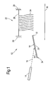
- FIG. 1 is a schematic illustration of the test apparatus 12.
- a gun 14 of known type fires a bird (not shown) along a trajectory 16 to impact on a surface 18 of a target 20.
- the angle of impact of the bird on the surface 18 is ⁇ .
- the fragmented bird is deflected off the surface 18 towards a soft-recovery system 22.
- This comprises a number of large plastic sacks 24 freely suspended on two parallel ropes 26 (only one is visible).
- the ropes 26 are rigidly fixed at their ends to structure 28.
- ten sacks 24 are used, but any suitable number may be employed.
- the sacks 24 absorb energy from the bird fragments without damaging them, allowing them to fall on to a sheet 30 on the floor for collection and analysis.
- High-speed video was used to record each test, and a picture of the target 20 was taken after each test.
- the extent of the splatter pattern on the target gives an indication of the spread of broken bird pieces from the impact site.
- the bird fragments were collected and laid out for measurement. The largest fragments were weighed and measured, the number of fragments was counted and the total mass recovered was measured.
- the "flexible” plate was a grade 316 stainless steel plate approximately 4mm thick, with dimensions between the supports of 500mm wide and 700mm long. This plate was restrained at its top 32 and bottom 34 edges only, leaving the side edges unrestrained.
- the "rigid” plate was a mild steel plate 25mm thick, 1000mmm long and 800mm wide. This plate was firmly clamped around its whole circumference to a massive support.
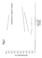
- Figure 2 shows the relationship between bird mass and the size of the largest fragment after impact. Tests were carried out on birds with masses between about 3.5oz (0.1kg) and about 81b (3.6kg), and the size of the largest fragment (as a percentage of the bird mass) was graphed against bird mass. These tests were performed with impact velocities of between about 78 knots (40m/s) and about 486 knots (250m/s). It was observed that there was a general trend for the proportional size of the largest fragment to increase with increasing bird mass.
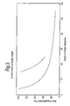
- Figure 3 shows the relationship between angle of impact and the size of the largest fragment after impact. Tests were carried out with both rigid and flexible targets, and with angles of impact between about 5 degrees and about 55 degrees, and the size of the largest fragment (as a percentage of the bird mass) was graphed against angle of impact. These tests were performed with impact velocities of between 40m/s and 250m/s. It was observed that there was a general trend for birds to break up less on flexible targets than on rigid targets.
- Figure 4 shows the relationship between impact velocity and the size of the largest fragment after impact. Tests were carried out with birds of different weights, different impact angles and both flexible and rigid targets. The tests were performed with impact velocities between about 40 m/s and about 250 m/s. It was observed that there was a general trend for birds to break up more at higher velocity (that is, the proportional size of the largest fragment tends to decrease with increasing impact velocity).
- the apparatus also included a splitter, a vertical plate designed to replicate an engine fan blade.
- the splitter was also mounted on lateral sliding roller rails, so that momentum transfer could be calculated for any debris striking it.
- a catcher box likewise mounted on lateral sliding roller rails, was also provided to receive the fragments of each bird.
- the slurry tends to leave the plate in a diverging, cone-shaped trajectory.
- the slurry leaves a roughly triangular trail on the target plate.
- Video images of the target plates were analysed, and trigonometry was used to calculate the angle of divergence of the slurry as it leaves the plate.
- the slurry model comprised a large number of spheres of about 0.5g each, arranged in several sections of square matrix.
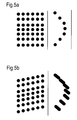
- Figure 5a shows a part of this model. This model gave a splitter velocity far lower than had been seen in the actual tests. It was observed that it was possible for the splitter to pass between two adjacent rows of balls, and so the model was adjusted to offset successive rows of balls, as shown in Figure 5b . This did increase the velocity of the splitter, but not to the level that was measured in the experiments.
- the model was modified in several ways to try to reproduce the splitter velocity seen in the tests.
- the slurry was made more compact; the balls were made larger; and solid, rather than hollow, balls were used.
- the catcher box velocity observed in the computational analyses was initially far higher than was seen in the actual tests. It was concluded that this was caused by two effects - firstly, the conditions of the slurry that achieve the optimum momentum transfer into the splitter velocity will tend to transfer too much momentum into the catcher box; secondly, actual slurry diverges whereas the modelled slurry did not, so too much slurry was hitting the catcher. To overcome this problem, the slurry was first modified by progressively reducing the diameter of the spheres, from 8mm in the centre down to 1mm at the edges of the slurry.
- Figure 6 shows the slurry modelled by spheres 72 of uniform size, and also shows the modelled representations of the splitter 74 and catcher box 76.
- Figure 7 shows the modified slurry, modelled by spheres 82 whose size reduces progressively from the centre 88 to the periphery 90 of the slurry.
- the invention can be used in any application in which a bird or other similar soft body is in collision with a stationary surface, and in which it is desirable to understand the behaviour of the system after the collision.
Landscapes
- Engineering & Computer Science (AREA)
- Mechanical Engineering (AREA)
- General Engineering & Computer Science (AREA)
- Physics & Mathematics (AREA)
- General Physics & Mathematics (AREA)
- Management, Administration, Business Operations System, And Electronic Commerce (AREA)
- Investigating Strength Of Materials By Application Of Mechanical Stress (AREA)
- Crushing And Pulverization Processes (AREA)
Abstract
Description
- This invention relates to the design of gas turbine engines, and more particularly to the characterisation of bird impacts, which are a particular problem when such engines are used in aircraft.
- Bird impacts can be very damaging to gas turbine engines, and it is necessary to design engines so that they can be safely run on for a period of time after an impact or, at the very least, safely shut down without causing danger to the aircraft or passengers.
- The basic techniques for carrying out bird ingestion tests on gas turbine engines are well known, and need not be discussed in detail here.
- In such a test, a soft body is fired at a known position on the inlet of the engine. The soft body may be either a dead bird or an artificial soft body designed to replicate closely the impact behaviour of a real bird. Such artificial soft bodies are well known. In the following description, the term "bird" can generally be taken to refer either to a real bird or to an artificial soft body used in a test in place of a real bird. After an impacting bird first hits the structure of the engine (whether static or rotating structure) it will fragment. Damage may be caused to the downstream parts of the engine by these fragments, and the size and trajectories of the fragments will determine the extent of this damage. Normally, the fragmentation can be assessed by viewing photographs or video of the first impact. The observed fragmentation can then be used to model the behaviour of the different parts of the engine following an impact, and thereby to design the engine to minimise damage from bird strikes.
- However, there is a problem when an engine is fitted with an obscuring intake. Such intakes are commonly used on military engines, so that the structure of the intake shields the hot components of the engine and prevents its detection by radar or other systems. The problem is that an incoming bird will strike the surface of the intake and will fragment, but the fragments are then hidden within the intake and so it is not possible to assess their size and trajectories. To obtain an initial bird condition for analysis, it is necessary to perform a separate impact test for each impact condition. This is time-consuming and expensive.
- Previously, impact analyses have been undertaken using a whole, intact bird, a bird fragment or a non-validated slurry.
- For the analysis of the bird strike capabilities of engines that will in use be shielded by an obscuring intake, it is vital that the initial conditions of the bird, which are used for analysis, reflect reality. Following a light impact of a bird on the intake, the bird can be modelled as a single fragment whose mass corresponds to that of the largest bird fragment. Following a severe impact, the bird can be modelled as a slurry. In between these two extremes of impact, the bird can be modelled as a combination of fragment(s) and slurry.
- There has previously been no method, other than an actual test, to predict what size bird fragment to use for analysis or what the initial conditions and composition of the slurry should be.
- The invention provides a method for characterising the fragmentation of a bird following impact with a surface as set out in the claims. Because the method allows prediction of how much a bird is likely to break up under different conditions, fewer or no actual bird impact tests are required before the engine modelling can be performed.
- Embodiments of the invention will now be described, by way of example, with reference to the drawings in which
-
Figure 1 is a schematic illustration of the test apparatus; -
Figure 2 is a graph of size of largest fragment against mass of bird; -
Figure 3 is a graph of size of largest fragment against impact angle; -
Figure 4 is a graph of size of largest fragment against velocity of impact; -
Figures 5a and 5b show schematically two arrangements of spheres in a computational model of a slurry; -
Figure 6 shows the initial computational model of the slurry; and -
Figure 7 shows the modified computational model of the slurry. - Bird impact tests have previously been carried out to characterise the behaviour of birds after an angled impact on a target plate. In these tests, and the subsequent modelling, it was assumed that, after the impact, the bird could be modelled as a slurry. This approach proved successful for modelling tests with a high impact speed, in which the component of the bird's velocity normal to the target plate was large. However, analysis of high-speed video of these tests showed that as the normal velocity of the bird on to the target plate decreased, more and more of the bird remained intact. The slurry model for the bird behaviour was clearly inadequate.
- The inventors therefore conducted a number of bird impact tests to determine the extent of fragmentation under different conditions. A special apparatus was used to enable the fragments to be recovered undamaged. The masses of the fragments could then be determined.
-
Figure 1 is a schematic illustration of thetest apparatus 12. Agun 14 of known type fires a bird (not shown) along atrajectory 16 to impact on asurface 18 of atarget 20. The angle of impact of the bird on thesurface 18 is □. The fragmented bird is deflected off thesurface 18 towards a soft-recovery system 22. This comprises a number of largeplastic sacks 24 freely suspended on two parallel ropes 26 (only one is visible). Theropes 26 are rigidly fixed at their ends to structure 28. In this embodiment, tensacks 24 are used, but any suitable number may be employed. Thesacks 24 absorb energy from the bird fragments without damaging them, allowing them to fall on to asheet 30 on the floor for collection and analysis. - High-speed video was used to record each test, and a picture of the
target 20 was taken after each test. The extent of the splatter pattern on the target gives an indication of the spread of broken bird pieces from the impact site. - After each test, the bird fragments were collected and laid out for measurement. The largest fragments were weighed and measured, the number of fragments was counted and the total mass recovered was measured.
- The following parameters were varied during the tests to assess their effect on the fragmentation of the birds - impact angle (□ between 4 and 55 degrees); mass of bird (between about 3.5oz (0.1kg) and about 81b (3.6kg); rigidity of surface; and velocity of impact (between about 50 knots (25.7m/s) and 500 knots (257.4m/s)).
- Two standards of target plate were used in these tests. The "flexible" plate was a grade 316 stainless steel plate approximately 4mm thick, with dimensions between the supports of 500mm wide and 700mm long. This plate was restrained at its
top 32 andbottom 34 edges only, leaving the side edges unrestrained. The "rigid" plate was a mild steel plate 25mm thick, 1000mmm long and 800mm wide. This plate was firmly clamped around its whole circumference to a massive support. - Graphing the fragment properties against the input conditions, for the different values of these parameters, has allowed the inventors to derive mathematical relationships that will predict the post-impact fragmentation of a bird.
-
Figure 2 shows the relationship between bird mass and the size of the largest fragment after impact. Tests were carried out on birds with masses between about 3.5oz (0.1kg) and about 81b (3.6kg), and the size of the largest fragment (as a percentage of the bird mass) was graphed against bird mass. These tests were performed with impact velocities of between about 78 knots (40m/s) and about 486 knots (250m/s). It was observed that there was a general trend for the proportional size of the largest fragment to increase with increasing bird mass. -
Figure 3 shows the relationship between angle of impact and the size of the largest fragment after impact. Tests were carried out with both rigid and flexible targets, and with angles of impact between about 5 degrees and about 55 degrees, and the size of the largest fragment (as a percentage of the bird mass) was graphed against angle of impact. These tests were performed with impact velocities of between 40m/s and 250m/s. It was observed that there was a general trend for birds to break up less on flexible targets than on rigid targets. -
Figure 4 shows the relationship between impact velocity and the size of the largest fragment after impact. Tests were carried out with birds of different weights, different impact angles and both flexible and rigid targets. The tests were performed with impact velocities between about 40 m/s and about 250 m/s. It was observed that there was a general trend for birds to break up more at higher velocity (that is, the proportional size of the largest fragment tends to decrease with increasing impact velocity). - The information presented so far concerns the modelling of bird fragments. As outlined above, it is appropriate to model the bird's fragmentation purely in terms of fragments for relatively light impacts. For more severe impacts, it is also necessary to model the behaviour of a slurry, and this will now be explained in more detail.
- Impact tests were conducted in which a bird was fired at an angled target plate. This target plate was mounted on lateral sliding roller rails, which in use allow the target plate to move almost without friction. In use, when a bird strikes the target plate, the transfer of momentum causes the target plate to move along the roller rails. By measuring the distance moved, and the velocity of the target plate's movement, the quantity of momentum transferred can be measured.
- The apparatus also included a splitter, a vertical plate designed to replicate an engine fan blade. The splitter was also mounted on lateral sliding roller rails, so that momentum transfer could be calculated for any debris striking it. A catcher box, likewise mounted on lateral sliding roller rails, was also provided to receive the fragments of each bird.
- After a bird impact on a target plate, the slurry tends to leave the plate in a diverging, cone-shaped trajectory. The slurry leaves a roughly triangular trail on the target plate. Video images of the target plates were analysed, and trigonometry was used to calculate the angle of divergence of the slurry as it leaves the plate.
- The results of these calculations were then used to set boundary conditions in a computational model of the splitter and catcher box. A commercially available finite element analysis program was used for the computational model. The intention of this modelling was to find a definition for a slurry model that would reproduce the displacements and velocities of the splitter and catcher box observed during the actual tests.
- Initially, the slurry model comprised a large number of spheres of about 0.5g each, arranged in several sections of square matrix.
Figure 5a shows a part of this model. This model gave a splitter velocity far lower than had been seen in the actual tests. It was observed that it was possible for the splitter to pass between two adjacent rows of balls, and so the model was adjusted to offset successive rows of balls, as shown inFigure 5b . This did increase the velocity of the splitter, but not to the level that was measured in the experiments. - The model was modified in several ways to try to reproduce the splitter velocity seen in the tests. The slurry was made more compact; the balls were made larger; and solid, rather than hollow, balls were used.
- The catcher box velocity observed in the computational analyses was initially far higher than was seen in the actual tests. It was concluded that this was caused by two effects - firstly, the conditions of the slurry that achieve the optimum momentum transfer into the splitter velocity will tend to transfer too much momentum into the catcher box; secondly, actual slurry diverges whereas the modelled slurry did not, so too much slurry was hitting the catcher. To overcome this problem, the slurry was first modified by progressively reducing the diameter of the spheres, from 8mm in the centre down to 1mm at the edges of the slurry.
-
Figure 6 shows the slurry modelled byspheres 72 of uniform size, and also shows the modelled representations of thesplitter 74 andcatcher box 76. -
Figure 7 shows the modified slurry, modelled byspheres 82 whose size reduces progressively from the centre 88 to theperiphery 90 of the slurry. - This modification improved the accuracy of the catcher box velocity, and a further improvement was obtained by giving the spheres a diverging trajectory.
- It will be appreciated that alternative embodiments of the invention are possible, besides those described.
- In particular, it will be appreciated that the invention can be used in any application in which a bird or other similar soft body is in collision with a stationary surface, and in which it is desirable to understand the behaviour of the system after the collision.
Claims (11)
- A method for characterising the fragmentation of a soft body following impact with a surface, comprising the steps of:obtaining values for the mass and velocity of the soft body;obtaining a value for the impact angle of the soft body on the surface;obtaining a value for the stiffness of the surface; processing the obtained values to generate parameters characterising the fragmentation of the soft body.
- A method as claimed in claim 1, in which the generated parameters comprise fragment mass and initial trajectory for at least one fragment.
- A method as claimed in claim 1, in which the generated parameters define at least one fragment and at least one slurry.
- A method as claimed in any preceding claim, in which the surface is part of a gas turbine engine.
- A method as claimed in claim 4, in which the surface is part of an obscuring intake.
- A method as claimed in claim 3, in which the slurry is defined by a plurality of spheres.
- A method as claimed in claim 6, in which the mass of the slurry is concentrated near its centre.
- A method as claimed in claim 6 or claim 7, in which the spheres defining the slurry are larger near its centre and smaller near its periphery.
- A method as claimed in any one of claims 6 to 8, in which the spheres defining the slurry are arranged in layers of differently sized spheres.
- A method as claimed in any one of claims 6 to 9, in which the spheres defining the slurry have a diverging trajectory.
- A method substantially as described in this specification with reference to the drawings.
Applications Claiming Priority (1)
| Application Number | Priority Date | Filing Date | Title |
|---|---|---|---|
| GBGB0807482.5A GB0807482D0 (en) | 2008-04-25 | 2008-04-25 | Characterisation of soft body impacts |
Publications (2)
| Publication Number | Publication Date |
|---|---|
| EP2112333A2 true EP2112333A2 (en) | 2009-10-28 |
| EP2112333A3 EP2112333A3 (en) | 2015-09-02 |
Family
ID=39522486
Family Applications (1)
| Application Number | Title | Priority Date | Filing Date |
|---|---|---|---|
| EP09250834.0A Withdrawn EP2112333A3 (en) | 2008-04-25 | 2009-03-24 | Charactersation of soft body impacts |
Country Status (5)
| Country | Link |
|---|---|
| US (1) | US8280704B2 (en) |
| EP (1) | EP2112333A3 (en) |
| JP (1) | JP2009264376A (en) |
| AU (1) | AU2009201425A1 (en) |
| GB (1) | GB0807482D0 (en) |
Cited By (3)
| Publication number | Priority date | Publication date | Assignee | Title |
|---|---|---|---|---|
| EP2239551A1 (en) * | 2009-04-07 | 2010-10-13 | Rolls-Royce plc | Characterisation of soft body impacts |
| CN113654754A (en) * | 2021-09-06 | 2021-11-16 | 北京理工大学 | Device and method for penetration test of broadside armor |
| CN114894418A (en) * | 2022-01-18 | 2022-08-12 | 中国人民解放军军事科学院国防工程研究院 | Anti-penetration test device for target plate with unidirectional translation and bidirectional rotation |
Families Citing this family (4)
| Publication number | Priority date | Publication date | Assignee | Title |
|---|---|---|---|---|
| GB0817855D0 (en) * | 2008-10-01 | 2008-11-05 | Rolls Royce Plc | Artificial bird projectiles for simulating bird strike events |
| US12590745B2 (en) | 2021-04-26 | 2026-03-31 | General Electric Company | Methods and apparatus for artificial bird manufacturing in impact testing |
| CN115979840A (en) * | 2023-01-18 | 2023-04-18 | 广州国显科技有限公司 | Impact test device and impact test method |
| CN116609017B (en) * | 2023-05-06 | 2025-09-23 | 西北工业大学 | A bird-cutting load measuring device and method based on Hopkinson bar |
Family Cites Families (6)
| Publication number | Priority date | Publication date | Assignee | Title |
|---|---|---|---|---|
| SU486245A1 (en) | 1974-01-28 | 1975-09-30 | Всесоюзный Ордена Трудового Красного Знамени Научно-Исследовательский Институт Буровой Техники | Installation for the study of the process of destruction of material by abrasive particles |
| JPH0861086A (en) | 1994-08-22 | 1996-03-05 | Toshiba Corp | Evaluation method for foreign matter collision damage on gas turbine blades |
| JP2000322407A (en) * | 1999-05-12 | 2000-11-24 | Toyota Central Res & Dev Lab Inc | Motion analysis method of medium in fluid |
| DE102004018579A1 (en) * | 2004-04-16 | 2005-11-03 | Airbus Deutschland Gmbh | Panel for a structure of an aircraft |
| GB0605070D0 (en) * | 2006-03-14 | 2006-04-26 | Rolls Royce Plc | An aerofoil |
| AU2007231919A1 (en) | 2006-04-04 | 2007-10-11 | Structural Monitoring Systems Ltd | Method for detecting impact damage in a structure |
-
2008
- 2008-04-25 GB GBGB0807482.5A patent/GB0807482D0/en not_active Ceased
-
2009
- 2009-03-24 EP EP09250834.0A patent/EP2112333A3/en not_active Withdrawn
- 2009-03-26 US US12/382,936 patent/US8280704B2/en not_active Expired - Fee Related
- 2009-04-03 JP JP2009090810A patent/JP2009264376A/en active Pending
- 2009-04-09 AU AU2009201425A patent/AU2009201425A1/en not_active Abandoned
Cited By (4)
| Publication number | Priority date | Publication date | Assignee | Title |
|---|---|---|---|---|
| EP2239551A1 (en) * | 2009-04-07 | 2010-10-13 | Rolls-Royce plc | Characterisation of soft body impacts |
| US8220309B2 (en) | 2009-04-07 | 2012-07-17 | Rolls-Royce Plc | Characterisation of soft body impacts |
| CN113654754A (en) * | 2021-09-06 | 2021-11-16 | 北京理工大学 | Device and method for penetration test of broadside armor |
| CN114894418A (en) * | 2022-01-18 | 2022-08-12 | 中国人民解放军军事科学院国防工程研究院 | Anti-penetration test device for target plate with unidirectional translation and bidirectional rotation |
Also Published As
| Publication number | Publication date |
|---|---|
| GB0807482D0 (en) | 2008-06-04 |
| EP2112333A3 (en) | 2015-09-02 |
| JP2009264376A (en) | 2009-11-12 |
| US8280704B2 (en) | 2012-10-02 |
| AU2009201425A1 (en) | 2009-11-12 |
| US20110178780A1 (en) | 2011-07-21 |
Similar Documents
| Publication | Publication Date | Title |
|---|---|---|
| EP2112333A2 (en) | Charactersation of soft body impacts | |
| EP2239551B1 (en) | Characterisation of soft body impacts | |
| CN102314537A (en) | Method for calculating damage probability of hedgehopping-and-upper-attacking smart ammunition | |
| Sielicki et al. | Field test and probabilistic analysis of irregular steel debris casualty risks from a person-borne improvised explosive device | |
| CN107798208A (en) | Air target guided missile fragment emission maximum injures algorithm | |
| Nishida et al. | Influence of impact angle on size distribution of fragments in hypervelocity impacts | |
| Zhao et al. | Prediction and validation of ash sticking probability under fouling conditions in pulverized coal combustion | |
| Iyer et al. | Hypervelocity impact response of Ti-6Al-4 V and commercially pure titanium | |
| Fras | On the effect of pitch and yaw angles in oblique impacts of small-caliber projectiles | |
| CN114580094A (en) | Bird collision damage engineering prediction method for rotation state of metal blade | |
| Van Vooren et al. | Sand penetration: A near nose investigation of a sand penetration event | |
| Dou et al. | Experimental and numerical investigation on high-velocity hail impact response of TC4 titanium alloy plates | |
| CN106649924A (en) | Method for determining anti-jet-penetration mechanism of rubber based composite target plate | |
| Omang et al. | Height of burst explosions: a comparative study of numerical and experimental results | |
| Verolme et al. | A method for backward calculation of debris in a post blast scene | |
| CN118640751A (en) | A warhead dynamic explosion force field test verification method and device | |
| Pedersen et al. | Behind-armor debris from the impact of hypervelocity tungsten penetrators | |
| Fasanella et al. | Test and analysis correlation of high speed impacts of ice cylinders | |
| Muster et al. | Ricochet quantification using a multiple sensor approach | |
| CN109740266A (en) | A kind of underground structure based on complexity effect field computation injures appraisal procedure | |
| Power | Fy 74 experimental hydraulic ram studies | |
| Nguyen et al. | Evaluation of the effect of the point angle and angle of incidence of a metal anchor on its docking state in a satellite structure for space debris mitigation | |
| RU98238U1 (en) | TRAP FOR A HIGH SPEED AEROBALLISTIC MODEL WITH TEST MATERIAL | |
| Beruto et al. | Debris shielding development for the Columbus Orbital Facility | |
| RU2846306C2 (en) | Method of armoured helmet testing for impact resistance and behind-armour effect during ammunition explosion |
Legal Events
| Date | Code | Title | Description |
|---|---|---|---|
| PUAI | Public reference made under article 153(3) epc to a published international application that has entered the european phase |
Free format text: ORIGINAL CODE: 0009012 |
|
| AK | Designated contracting states |
Kind code of ref document: A2 Designated state(s): AT BE BG CH CY CZ DE DK EE ES FI FR GB GR HR HU IE IS IT LI LT LU LV MC MK MT NL NO PL PT RO SE SI SK TR |
|
| AX | Request for extension of the european patent |
Extension state: AL BA RS |
|
| RAP1 | Party data changed (applicant data changed or rights of an application transferred) |
Owner name: ROLLS-ROYCE PLC |
|
| PUAL | Search report despatched |
Free format text: ORIGINAL CODE: 0009013 |
|
| AK | Designated contracting states |
Kind code of ref document: A3 Designated state(s): AT BE BG CH CY CZ DE DK EE ES FI FR GB GR HR HU IE IS IT LI LT LU LV MC MK MT NL NO PL PT RO SE SI SK TR |
|
| AX | Request for extension of the european patent |
Extension state: AL BA RS |
|
| RIC1 | Information provided on ipc code assigned before grant |
Ipc: G01M 7/08 20060101AFI20150730BHEP |
|
| AKX | Designation fees paid |
Designated state(s): DE FR GB |
|
| AXX | Extension fees paid |
Extension state: RS Extension state: AL Extension state: BA |
|
| STAA | Information on the status of an ep patent application or granted ep patent |
Free format text: STATUS: THE APPLICATION IS DEEMED TO BE WITHDRAWN |
|
| 18D | Application deemed to be withdrawn |
Effective date: 20160303 |