EP2112064A2 - Spherical elastomeric bearing with improved shim thickness - Google Patents
Spherical elastomeric bearing with improved shim thickness Download PDFInfo
- Publication number
- EP2112064A2 EP2112064A2 EP09005377A EP09005377A EP2112064A2 EP 2112064 A2 EP2112064 A2 EP 2112064A2 EP 09005377 A EP09005377 A EP 09005377A EP 09005377 A EP09005377 A EP 09005377A EP 2112064 A2 EP2112064 A2 EP 2112064A2
- Authority
- EP
- European Patent Office
- Prior art keywords
- shim
- bearing
- thickness
- elastomeric
- multitude
- Prior art date
- Legal status (The legal status is an assumption and is not a legal conclusion. Google has not performed a legal analysis and makes no representation as to the accuracy of the status listed.)
- Granted
Links
Images


Classifications
-
- B—PERFORMING OPERATIONS; TRANSPORTING
- B64—AIRCRAFT; AVIATION; COSMONAUTICS
- B64C—AEROPLANES; HELICOPTERS
- B64C27/00—Rotorcraft; Rotors peculiar thereto
- B64C27/32—Rotors
- B64C27/35—Rotors having elastomeric joints
-
- F—MECHANICAL ENGINEERING; LIGHTING; HEATING; WEAPONS; BLASTING
- F16—ENGINEERING ELEMENTS AND UNITS; GENERAL MEASURES FOR PRODUCING AND MAINTAINING EFFECTIVE FUNCTIONING OF MACHINES OR INSTALLATIONS; THERMAL INSULATION IN GENERAL
- F16F—SPRINGS; SHOCK-ABSORBERS; MEANS FOR DAMPING VIBRATION
- F16F1/00—Springs
- F16F1/36—Springs made of rubber or other material having high internal friction, e.g. thermoplastic elastomers
- F16F1/38—Springs made of rubber or other material having high internal friction, e.g. thermoplastic elastomers with a sleeve of elastic material between a rigid outer sleeve and a rigid inner sleeve or pin, i.e. bushing-type
- F16F1/393—Springs made of rubber or other material having high internal friction, e.g. thermoplastic elastomers with a sleeve of elastic material between a rigid outer sleeve and a rigid inner sleeve or pin, i.e. bushing-type with spherical or conical sleeves
-
- F—MECHANICAL ENGINEERING; LIGHTING; HEATING; WEAPONS; BLASTING
- F16—ENGINEERING ELEMENTS AND UNITS; GENERAL MEASURES FOR PRODUCING AND MAINTAINING EFFECTIVE FUNCTIONING OF MACHINES OR INSTALLATIONS; THERMAL INSULATION IN GENERAL
- F16F—SPRINGS; SHOCK-ABSORBERS; MEANS FOR DAMPING VIBRATION
- F16F1/00—Springs
- F16F1/36—Springs made of rubber or other material having high internal friction, e.g. thermoplastic elastomers
- F16F1/40—Springs made of rubber or other material having high internal friction, e.g. thermoplastic elastomers consisting of a stack of similar elements separated by non-elastic intermediate layers
-
- Y—GENERAL TAGGING OF NEW TECHNOLOGICAL DEVELOPMENTS; GENERAL TAGGING OF CROSS-SECTIONAL TECHNOLOGIES SPANNING OVER SEVERAL SECTIONS OF THE IPC; TECHNICAL SUBJECTS COVERED BY FORMER USPC CROSS-REFERENCE ART COLLECTIONS [XRACs] AND DIGESTS
- Y10—TECHNICAL SUBJECTS COVERED BY FORMER USPC
- Y10T—TECHNICAL SUBJECTS COVERED BY FORMER US CLASSIFICATION
- Y10T403/00—Joints and connections
- Y10T403/32—Articulated members
- Y10T403/32606—Pivoted
- Y10T403/32631—Universal ball and socket
- Y10T403/32737—Universal ball and socket including liner, shim, or discrete seat
Definitions
- the present invention relates to an elastomeric spherical bearing.
- elastomeric spherical bearing design is the smallest/lightest package that meets the desired design life requirements.
- Conventional spherical elastomeric bearing optimization procedures have only optimized the elastomeric layers and incorporated single thickness non-extensible layers such as metal shims throughout the entire bearing.
- An elastomeric spherical bearing includes a multitude of shims, each of said multitude of shims mounted between at least two of the multiple of elastomeric layers, a first shim of the multitude of shims having a first thickness and a second shim of the multitude of shims having a second thickness, the second thickness different than the first thickness.
- a method of calculating a nonresilient shim thickness for a spherical elastomeric bearing includes Determining a first thickness of a first of a multitude of nonresilient shim layers to satisfies a first set of criteria. Determining a second thickness of a second of the multitude of nonresilient shim layers outboard of the first of the multitude of nonresilient shim layers to satisfies a second set of criteria, the second thickness different than the first thickness.
- a method of calculating a nonresilient shim layer thickness for a spherical elastomeric bearing includes determining a first shim thickness of a first of a multitude of nonresilient shim layers in the spherical elastomeric bearing, each of the multitude of nonresilient shim layers sandwiched between a first pair of elastomeric layers. Determining a elastomeric layer thickness for the first pair of elastomeric layers.
- Figure 1 is a perspective view a rotor head assembly utilizing an elastomeric bearing according to one non-limiting embodiment of the present invention
- Figure 2A is an enlarged broken-away perspective view of the elastomeric bearing in combination with a rotor assembly yoke and shear segment of the rotor hub assembly of Figure 1 ;
- Figure 2B depicts an enlarged view of the elastomeric laminates of the elastomeric bearing of Figure 2A ;
- Figure 3 is a schematic sectional view of a spherical elastomeric layer of the elastomeric bearing design envelope
- Figure 4 is a schematic sectional view of a spherical elastomeric bearing with details of one inner elastomeric layer, one outer elastomeric layer and a nonresilient shim therebetween;
- Figure 5 is an expanded schematic sectional view of differential pressure on an inner surface and an outer surface of a nonresilient shim
- Figure 6A is an expanded schematic sectional view of an undeformed nonresilient shim
- Figure 6B is an expanded schematic sectional view of the nonresilient shim of Figure 6A in a deformed condition to illustrate the deformation mechanism which generates the primary shim stress;
- Figure 7A is a flow chart illustrating a calculation procedure for calculation of Compressive Load T c And Torsional Motion ( ⁇ ) according to one non-limiting embodiment
- Figure 7B is a flow chart illustrating a calculation procedure for calculation of Compressive Load ( T c ); Torsional Motion ( ⁇ ); And Cocking Motions ( ⁇ ) according to one non-limiting embodiment;
- Figure 8 is a graph representing a shim thickness relative a shim number for one elastomeric bearing with three shim layers according to one non-limiting embodiment of the present invention.
- Figure 9 is a graph of the elastomeric bearing of Figure 3 illustrating an essentially equivalent shim stress at each of the three shim layers.
- a rotor hub assembly 10 typical of a rotary-wing aircraft includes a hub retention member 12 which drives a multitude of rotor blade assemblies 14 about an axis of rotation 16.
- the hub retention member 12 includes a multitude of radial spokes 20 and shear segments 22.
- the yoke 24 is generally C-shaped and circumscribes, in looped fashion, the respective shear segment 22.
- the yoke 24 is disposed in combination with a cuff structures 28 which, in turn, mount to the root end of each rotor blade assembly 14.
- a spherical elastomeric bearing assembly 30 is interposed between each rotor assembly yoke 24 and the respective shear segment 22 to accommodate the multi-directional rotation of the rotor blade assembly 14.
- the spherical elastomeric bearing 30 is shown in combination with a rotor assembly yoke 24 and a respective shear segment 22. It should be understood that although a particular rotor hub application is illustrated in the disclosed non-limiting embodiment, elastomeric bearing for any application including but not limited to aerospace, heavy machinery, and civil engineering (bridges, buildings, etc.) will benefit herefrom.
- the spherical elastomeric bearing 30 includes a central bearing element 32 having a spherical bearing surface 32s which defines a bearing focal point 30f.
- the bearing focal point 30f defines the flap, lead-lag and pitch axes, Fa, La, and Pa, respectively, about which the rotor blade assembly articulates ( Figure 1 ).
- each spherical elastomeric element 34 includes a multiple of alternating layers (see Figure 2B ) of elastomer 36 and nonresilient shims 38, respectively, which are disposed at increasing radii from the bearing focal point 30f and have a center of curvature C c which is coincident therewith.
- Each nonresilient shim 38 of the elastomeric spherical bearing 30 is tailored to an improved, and in one exemplary embodiment an optimized, thickness as will be further described below.
- each nonresilient shim 38 away from the bearing focal point 30f increases in thickness.
- each nonresilient shim 38 is of an improved, and in an exemplary embodiment optimized, thickness the entire spherical elastomeric bearing size envelope and weight is improved and may be minimized.
- the improvement occurs because one or more of the nonresilient shims 38 has a calculated and fabricated size that is different from the thickness of another of the nonresilient shims 38. Optimization occurs, e.g., when each of the thicknesses of each of the nonresilient shims 38 is calculated according to certain criteria as discussed below.
- the elastomeric spherical bearing 30 is schematically illustrated such that nomenclature may be defined.
- the elastomeric spherical bearing 30 includes an outwardly facing convex surface 40 and an inwardly facing concave surface 42.
- a representative number of elastomer layers 36A, 36B, 36C, 36D sandwich a number of nonresilient shims 38A, 38B, 38C therebetween. It should be understood that any number of layers may be included and calculated according to the disclosure herein. It is noted that superscript or subscript "i” refers to elastomeric layers, while superscript or subscript "j" refers to shim layers.
- T ⁇ e Average Elastomer Thickness T i + T i + 1 2 in
- G Average Elastomer Shear Modulus G i + G i + 1 2 psi
- T c Axial Compressive Load (1b)
- one calculation procedure according to one non-limiting embodiment of the present invention is as follows:
- Step 1 Determine Loads and Motions.
- Step 2 Enter spherical elastomeric bearing dimensions. Inner radius ( R l ), Inner Angle ( B l ), Side Angle ( ⁇ ) sometimes referred to as outer taper angle, and Elastomer modulus of elasticity ( E ).
- Step 3 Use conventional spherical bearing methodology to design first elastomeric layer 36A ( Figure 4 ).
- Step 4 Assume metal shim thickness T s j
- Step 5 Repeat Step 3 for the next layer T e i + 1 ⁇ G e i + 1 ⁇ ⁇ ai + 1
- Step 6 Apply design module equations 1-9 in order to determine nonresilient shim thickness T s j that satisfies material strength allowables (e.g., specific to the material being used in the shim).
- Step 7 Finalize with existing design module equations 1-9. It is noted that the calculated nonresilient shim thickness determined in Step 6 may be modified by addition of another elastomeric layer, and thus Step 7 allows a further refinement of the determined nonresilient shim thickness T s j from Step 6. T e i + 1 ⁇ G e i + 1 ⁇ ⁇ ai + 1
- Step 8 Iterate from Step 4 until all elastomeric layers 36 and nonresilient shims 38 satisfy loads, motions and allowable constraints, e.g., material strength allowables and the constraints described in the aforementioned United States Patent Application No. 11/959,949 filed 12/19/2007 and entitled UNIFORM FATIGUE LIFE SPHERICAL ELASTOMERIC BEARING.
- loads, motions and allowable constraints e.g., material strength allowables and the constraints described in the aforementioned United States Patent Application No. 11/959,949 filed 12/19/2007 and entitled UNIFORM FATIGUE LIFE SPHERICAL ELASTOMERIC BEARING.
- an elastomeric bearing 30 with three nonresilient shims 38 has inputs delineated in the chart below: Inputs Bearing Parameters Side Angle, ALPHA (deg) 27 Inner Angle Bi (deg) 54.00 Inner Radius Ri (in) 7.25 Shim Layers Shim Elastic Modulus, E (psi) 3.00E+07 Shim Poisson's Ratio, v 0.3 Shim Hoop Stress Allowable (psi) 10,000 Applied Loads and Motions Axial Loads, Paxial (Ibf) 122,500 Torsional Rotation, theta (deg) 1.68 Flapping Rotation, beta (deg) 0.96
- a computing device can be used to implement various functionality and calculations of the design module equations to determine that each of the nonresilient shims satisfy the desired loads, motions, allowables and other requirements as described herein.
- a computing device can include a processor, memory, and one or more input and/or output (I/O) device interface(s) that are communicatively coupled via a local interface.
- the local interface can include, for example but not limited to, one or more buses and/or other wired or wireless connections.
- the local interface may have additional elements, which are omitted for simplicity, such as controllers, buffers (caches), drivers, repeaters, and receivers to enable communications. Further, the local interface may include address, control, and/or data connections to enable appropriate communications among the aforementioned components.
- the processor may be a hardware device for executing software, particularly software stored in memory.
- the processor can be a custom made or commercially available processor, a central processing unit (CPU), an auxiliary processor among several processors associated with the computing device, a semiconductor based microprocessor (in the form of a microchip or chip set) or generally any device for executing software instructions.
- the memory can include any one or combination of volatile memory elements (e.g., random access memory (RAM, such as DRAM, SRAM, SDRAM, VRAM, etc.)) and/or nonvolatile memory elements (e.g., ROM, hard drive, tape, CD-ROM, etc.).
- volatile memory elements e.g., random access memory (RAM, such as DRAM, SRAM, SDRAM, VRAM, etc.)
- nonvolatile memory elements e.g., ROM, hard drive, tape, CD-ROM, etc.
- the memory may incorporate electronic, magnetic, optical, and/or other types of storage media.
- the memory can also have a distributed architecture, where various components are situated remotely from one another, but can be accessed by the processor.
- the software in the memory may include one or more separate programs, each of which includes an ordered listing of executable instructions for implementing logical functions.
- a system component embodied as software may also be construed as a source program, executable program (object code), script, or any other entity comprising a set of instructions to be performed.
- the program is translated via a compiler, assembler, interpreter, or the like, which may or may not be included within the memory.
- the Input/Output devices that may be coupled to system I/O Interface(s) may include input devices, for example but not limited to, a keyboard, mouse, scanner, microphone, camera, proximity device, etc. Further, the Input/Output devices may also include output devices, for example but not limited to, a printer, display, etc. Finally, the Input/Output devices may further include devices that communicate both as inputs and outputs, for instance but not limited to, a modulator/demodulator (modem; for accessing another device, system, or network), a radio frequency (RF) or other transceiver, a telephonic interface, a bridge, a router, etc.
- modem for accessing another device, system, or network
- RF radio frequency
- the processor can be configured to execute software stored within the memory, to communicate data to and from the memory, and to generally control operations of the computing device pursuant to the software.
- Software in memory, in whole or in part, is read by the processor, perhaps buffered within the processor, and then executed.
Landscapes
- Engineering & Computer Science (AREA)
- General Engineering & Computer Science (AREA)
- Mechanical Engineering (AREA)
- Aviation & Aerospace Engineering (AREA)
- Architecture (AREA)
- Support Of The Bearing (AREA)
Abstract
Description
- The present invention relates to an elastomeric spherical bearing.
- One goal of elastomeric spherical bearing design is the smallest/lightest package that meets the desired design life requirements. Conventional spherical elastomeric bearing optimization procedures have only optimized the elastomeric layers and incorporated single thickness non-extensible layers such as metal shims throughout the entire bearing.
- An elastomeric spherical bearing according to an exemplary aspect of the present invention includes a multitude of shims, each of said multitude of shims mounted between at least two of the multiple of elastomeric layers, a first shim of the multitude of shims having a first thickness and a second shim of the multitude of shims having a second thickness, the second thickness different than the first thickness.
- A method of calculating a nonresilient shim thickness for a spherical elastomeric bearing according to an exemplary aspect of the present invention includes Determining a first thickness of a first of a multitude of nonresilient shim layers to satisfies a first set of criteria. Determining a second thickness of a second of the multitude of nonresilient shim layers outboard of the first of the multitude of nonresilient shim layers to satisfies a second set of criteria, the second thickness different than the first thickness.
- A method of calculating a nonresilient shim layer thickness for a spherical elastomeric bearing according to an exemplary aspect of the present invention includes determining a first shim thickness of a first of a multitude of nonresilient shim layers in the spherical elastomeric bearing, each of the multitude of nonresilient shim layers sandwiched between a first pair of elastomeric layers. Determining a elastomeric layer thickness for the first pair of elastomeric layers. Modifying the first shim thickness and the elastomeric layer thickness in response to an addition of a second a of the multitude of nonresilient shim layers and a second pair of elastomeric layers outboard of the first of the multitude of nonresilient shim layers and the first pair of elastomeric layers, the modifying continuing until each of the multitude of nonresilient shim layers have a generally equivalent stress.
- The various features and advantages of this invention will become apparent to those skilled in the art from the following detailed description of the currently disclosed embodiment. The drawings that accompany the detailed description can be briefly described as follows:
-
Figure 1 is a perspective view a rotor head assembly utilizing an elastomeric bearing according to one non-limiting embodiment of the present invention; -
Figure 2A is an enlarged broken-away perspective view of the elastomeric bearing in combination with a rotor assembly yoke and shear segment of the rotor hub assembly ofFigure 1 ; -
Figure 2B depicts an enlarged view of the elastomeric laminates of the elastomeric bearing ofFigure 2A ; -
Figure 3 is a schematic sectional view of a spherical elastomeric layer of the elastomeric bearing design envelope; -
Figure 4 is a schematic sectional view of a spherical elastomeric bearing with details of one inner elastomeric layer, one outer elastomeric layer and a nonresilient shim therebetween; -
Figure 5 is an expanded schematic sectional view of differential pressure on an inner surface and an outer surface of a nonresilient shim; -
Figure 6A is an expanded schematic sectional view of an undeformed nonresilient shim; -
Figure 6B is an expanded schematic sectional view of the nonresilient shim ofFigure 6A in a deformed condition to illustrate the deformation mechanism which generates the primary shim stress; -
Figure 7A is a flow chart illustrating a calculation procedure for calculation of Compressive Load Tc And Torsional Motion (θ) according to one non-limiting embodiment; -
Figure 7B is a flow chart illustrating a calculation procedure for calculation of Compressive Load (Tc ); Torsional Motion (θ); And Cocking Motions (β) according to one non-limiting embodiment; -
Figure 8 is a graph representing a shim thickness relative a shim number for one elastomeric bearing with three shim layers according to one non-limiting embodiment of the present invention; and -
Figure 9 is a graph of the elastomeric bearing ofFigure 3 illustrating an essentially equivalent shim stress at each of the three shim layers. - Referring to
Figure 1 , arotor hub assembly 10 typical of a rotary-wing aircraft includes ahub retention member 12 which drives a multitude ofrotor blade assemblies 14 about an axis ofrotation 16. - The
hub retention member 12 includes a multitude ofradial spokes 20 andshear segments 22. Eachshear segment 22, in combination with its respectiveradial spokes 20, form a structural loop for accepting arotor assembly yoke 24. Theyoke 24 is generally C-shaped and circumscribes, in looped fashion, therespective shear segment 22. Theyoke 24 is disposed in combination with acuff structures 28 which, in turn, mount to the root end of eachrotor blade assembly 14. - A spherical
elastomeric bearing assembly 30 is interposed between eachrotor assembly yoke 24 and therespective shear segment 22 to accommodate the multi-directional rotation of therotor blade assembly 14. - Referring to
Figure 2A , the sphericalelastomeric bearing 30 is shown in combination with arotor assembly yoke 24 and arespective shear segment 22. It should be understood that although a particular rotor hub application is illustrated in the disclosed non-limiting embodiment, elastomeric bearing for any application including but not limited to aerospace, heavy machinery, and civil engineering (bridges, buildings, etc.) will benefit herefrom. - The spherical elastomeric bearing 30 includes a central bearing
element 32 having a spherical bearingsurface 32s which defines a bearingfocal point 30f. The bearingfocal point 30f defines the flap, lead-lag and pitch axes, Fa, La, and Pa, respectively, about which the rotor blade assembly articulates (Figure 1 ). - To the
spherical surface 32s is bonded discrete sphericalelastomeric elements 34 about the bearingfocal point 30f. Furthermore, each sphericalelastomeric element 34 includes a multiple of alternating layers (seeFigure 2B ) ofelastomer 36 andnonresilient shims 38, respectively, which are disposed at increasing radii from the bearingfocal point 30f and have a center of curvature Cc which is coincident therewith. - Each
nonresilient shim 38 of the elastomeric spherical bearing 30 is tailored to an improved, and in one exemplary embodiment an optimized, thickness as will be further described below. Generally, eachnonresilient shim 38 away from the bearingfocal point 30f increases in thickness. As eachnonresilient shim 38 is of an improved, and in an exemplary embodiment optimized, thickness the entire spherical elastomeric bearing size envelope and weight is improved and may be minimized. The improvement occurs because one or more of thenonresilient shims 38 has a calculated and fabricated size that is different from the thickness of another of thenonresilient shims 38. Optimization occurs, e.g., when each of the thicknesses of each of thenonresilient shims 38 is calculated according to certain criteria as discussed below. - Referring to
Figure 3 , the elastomeric spherical bearing 30 is schematically illustrated such that nomenclature may be defined. The elastomeric spherical bearing 30 includes an outwardly facingconvex surface 40 and an inwardly facingconcave surface 42. A representative number ofelastomer layers nonresilient shims - Symbols (see
Figures 3, 4 ,5, 6A and 6B ) - T̂e = Average Elastomer Thickness

- Ts = Shim Thickness Ts j (in)
- T̂s = Average Shim Thickness (in)
- µ = Shim Poison Ratio
- E = Shim Modulus of Elasticity (psi)
- Rs = Shim Median Spherical Radius Rj (in)
- G = Average Elastomer Shear Modulus

- Bl = Bearing Inner Wrap Angle (deg)
- Bo = Bearing Outer Wrap Angle (deg)
- Ns = Total Number of Shims
- Bs = Outer Wrap Around Angle of Shim

- D = Shim Bending Stiffness Term (1b-in)
- BET = Shim Geometric Stiffness Term (in)
- γ = Average Elastomer Compression Induced Shear Strain (in/in)/100
- TT = Total Bearing Elastomer Thickness (in)
- Q = Averaging Coefficient of Bearing (non-dimensional)
- ν = Averaging Coefficient of Elastomer To Shim Context (non-dimensional)
- LL = Unsupported Spherical Arc of Shim

Figure 4 ) - YY = Radial Deflection of Shim

Figure 4 ) - σθ = Shim Hoop Stress σθi (psi)
- DP = Differential Resultant Pressure Load On Unsupported Spherical Arc of Shim Li L
- Tc = Axial Compressive Load (1b)
- θ = Torsional Motion Angle (deg)
- β = Cocking Motion Angle (deg)
- Tc · sin·β = Radial Load (1b)
- Rl = Bearing Inner Radius (in)
- Ro = Bearing Outer Radius (in)
-

- α = Bearing Outer Taper Angle (deg)
- SHIM STRESS DESIGN MODULE EQUATIONS


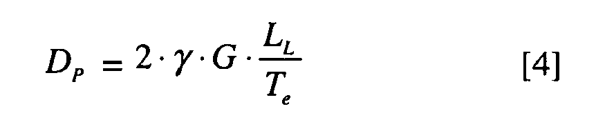


- Equations 1-9 are combined to generate the following equation:

- Referring to
Figure 7A , utilizing the Equations described above, one calculation procedure according to one non-limiting embodiment of the present invention is as follows: - CALCULATE SHIM STRESS
- CASE I
- Compressive Load Tc And Torsional Motion (θ) Calculation
-
Step 1. Determine Loads and Motions. - a. Determine the axial load. The axial load acts in a direction parallel to the bearing Z axis of rotation. For rotary-wing aircraft, this is generally the centrifugal force from the
rotor blade 14. - b. Determine the radial load. The radial load acts in the R, radial direction. This is generally the shear load on the
rotor blade 14. - c. Determine the vibratory pitch motion (θ) angle. This motion rotates about the Z axis and is sometimes referred to as the torsional rotation. This motion is a vibratory motion. The angle is a plus or minus motion from the origin.
- d. Determine the flapping (cocking β) motion angle. (used in Case II below).
- e. Determine shim stress allowable (in psi).
-
Step 2. Enter spherical elastomeric bearing dimensions. Inner radius (Rl ), Inner Angle (Bl ), Side Angle (α) sometimes referred to as outer taper angle, and Elastomer modulus of elasticity (E). -
Step 3. Use conventional spherical bearing methodology to design firstelastomeric layer 36A (Figure 4 ). For further understanding of other aspects of the conventional spherical bearing methodology, attention is directed to United States Patent Application No.11/959,949 filed 12/19/2007 

-
Step 4. Assume metal shim thickness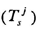
-
Step 5.Repeat Step 3 for the next layer
- Step 6. Apply design module equations 1-9 in order to determine nonresilient shim thickness

-
Step 7. Finalize with existing design module equations 1-9. It is noted that the calculated nonresilient shim thickness determined in Step 6 may be modified by addition of another elastomeric layer, and thusStep 7 allows a further refinement of the determined nonresilient shim thickness

- Step 8. Iterate from
Step 4 until allelastomeric layers 36 andnonresilient shims 38 satisfy loads, motions and allowable constraints, e.g., material strength allowables and the constraints described in the aforementioned United States Patent Application No.11/959,949 filed 12/19/2007 - Referring to
Figure 7B , utilizing the Equations described above, another calculation procedure according to one non-limiting embodiment of the present invention is as follows: - CASE II
- Compressive Load (Tc ); Torsional Motion (θ); And Cocking Motions (β) Calculation
- Follow Case I Module but:
- Adjust equation 6 to reflect the change in differential support zone due to the cocking.

- Adjust
equation 7 to reflect the radial loading Tc · sin· β due to the cocking motion with associated radial and axial compression induced shear strain.
- Modification of
equations 6 and 7 incorporate blade flapping in the stress calculation. Follow Case I Design Optimization Module where the shim stress equations are combined toequation 10 until all elastomeric layers and nonresilient shims satisfy load, motions and allowable constraints. - It should be understood that the instructions are equivalent for a solid bearing and a bearing with a central opening. It should also be understood that an elastomeric bearing with any number of layers may be calculated by the method herein.
- By way of illustration, an
elastomeric bearing 30 with threenonresilient shims 38 according to one non-limiting embodiment, has inputs delineated in the chart below:Inputs Bearing Parameters Side Angle, ALPHA (deg) 27 Inner Angle Bi (deg) 54.00 Inner Radius Ri (in) 7.25 Shim Layers Shim Elastic Modulus, E (psi) 3.00E+07 Shim Poisson's Ratio, v 0.3 Shim Hoop Stress Allowable (psi) 10,000 Applied Loads and Motions Axial Loads, Paxial (Ibf) 122,500 Torsional Rotation, theta (deg) 1.68 Flapping Rotation, beta (deg) 0.96 - To provide the following properties:
Final Bearing Properties Geometry Inner Radius Ri (in) 7.25 Outer Radius Ro (in) 7.90 Inner Angle Bi (deg) 54.00 Outer Angle Bo (deg) 51.62 Side Angle, ALPHA (deg) 27 Average Shim Thickness (in) 0.040 Total Elastomer Thickness, Tt (in) 0.531 Number of shims, Ns 3 Number of Elastomer Layers 4 - These properties provide a
nonresilient shim Figure 8 ) such that each nonresilient shim 38A, 38B, 38C is subject to an essentially equivalent stress level (Figure 9 ). - It should be noted that a computing device can be used to implement various functionality and calculations of the design module equations to determine that each of the nonresilient shims satisfy the desired loads, motions, allowables and other requirements as described herein. In terms of hardware architecture, such a computing device can include a processor, memory, and one or more input and/or output (I/O) device interface(s) that are communicatively coupled via a local interface. The local interface can include, for example but not limited to, one or more buses and/or other wired or wireless connections. The local interface may have additional elements, which are omitted for simplicity, such as controllers, buffers (caches), drivers, repeaters, and receivers to enable communications. Further, the local interface may include address, control, and/or data connections to enable appropriate communications among the aforementioned components.
- The processor may be a hardware device for executing software, particularly software stored in memory. The processor can be a custom made or commercially available processor, a central processing unit (CPU), an auxiliary processor among several processors associated with the computing device, a semiconductor based microprocessor (in the form of a microchip or chip set) or generally any device for executing software instructions.
- The memory can include any one or combination of volatile memory elements (e.g., random access memory (RAM, such as DRAM, SRAM, SDRAM, VRAM, etc.)) and/or nonvolatile memory elements (e.g., ROM, hard drive, tape, CD-ROM, etc.). Moreover, the memory may incorporate electronic, magnetic, optical, and/or other types of storage media. Note that the memory can also have a distributed architecture, where various components are situated remotely from one another, but can be accessed by the processor.
- The software in the memory may include one or more separate programs, each of which includes an ordered listing of executable instructions for implementing logical functions. A system component embodied as software may also be construed as a source program, executable program (object code), script, or any other entity comprising a set of instructions to be performed. When constructed as a source program, the program is translated via a compiler, assembler, interpreter, or the like, which may or may not be included within the memory.
- The Input/Output devices that may be coupled to system I/O Interface(s) may include input devices, for example but not limited to, a keyboard, mouse, scanner, microphone, camera, proximity device, etc. Further, the Input/Output devices may also include output devices, for example but not limited to, a printer, display, etc. Finally, the Input/Output devices may further include devices that communicate both as inputs and outputs, for instance but not limited to, a modulator/demodulator (modem; for accessing another device, system, or network), a radio frequency (RF) or other transceiver, a telephonic interface, a bridge, a router, etc.
- When the computing device is in operation, the processor can be configured to execute software stored within the memory, to communicate data to and from the memory, and to generally control operations of the computing device pursuant to the software. Software in memory, in whole or in part, is read by the processor, perhaps buffered within the processor, and then executed.
- It should be understood that relative positional terms such as "forward," "aft," "upper," "lower," "above," "below," and the like are with reference to the normal operational attitude of the vehicle and should not be considered otherwise limiting.
- It should be understood that although a particular component arrangement is disclosed in the illustrated embodiment, other arrangements will benefit from the instant invention.
- Although particular step sequences are shown, described, and claimed, it should be understood that steps may be performed in any order, separated or combined unless otherwise indicated and will still benefit from the present invention.
- The foregoing description is exemplary rather than defined by the limitations within. Many modifications and variations of the present invention are possible in light of the above teachings. The disclosed embodiments of this invention have been disclosed, however, one of ordinary skill in the art would recognize that certain modifications would come within the scope of this invention. It is, therefore, to be understood that within the scope of the appended claims, the invention may be practiced otherwise than as specifically described. For that reason the following claims should be studied to determine the true scope and content of this invention.
Claims (15)
- An elastomeric spherical bearing comprising:a multitude of elastomeric layers defined about a bearing focal point; anda multitude of shims, each of said multitude of shims mounted between at least two of said multiple of elastomeric layers, a first shim of said multitude of shims having a first thickness and a second shim of said multitude of shims having a second thickness, said second thickness different than said first thickness.
- The elastomeric spherical bearing as recited in claim 1, wherein an inner layer of said multiple of elastomeric layers is mounted to a central bearing element having a spherical bearing surface.
- The elastomeric spherical bearing as recited in claim 2, wherein an inner layer of said multiple of elastomeric layers is mounted to a rotor assembly component.
- The elastomeric spherical bearing as recited in claim 2 or 3, wherein an outer layer of said multiple of elastomeric layers is mounted to a cuff structures of a rotor assembly.
- The elastomeric spherical bearing as recited in any of claims 1 to 4, wherein said multitude of shims are arranged relative to said bearing focal point such that each of said multitude of shims increase in thickness relative an adjacent inboard shim.
- The elastomeric spherical bearing as recited in any of claims 1 to 5, wherein each of said multitude of shims have a generally equivalent stress level.
- A method of calculating a nonresilient shim thickness for a spherical elastomeric bearing comprising:determining a first thickness of a first of a multitude of nonresilient shim layers to satisfies a first set of criteria;determining a second thickness of a second of the multitude of nonresilient shim layers outboard of the first of the multitude of nonresilient shim layers to satisfies a second set of criteria, the second thickness different than the first thickness.
- A method as recited in claim 9, further comprising:determining the first thickness and the second thickness to generate a generally equivalent stress in each of the multitude of nonresilient shim layers.
- A method as recited in claim 9 or 10, further comprising:utilizing material strength allowables of each of the multitude of nonresilient shim layers at least in part as the first criteria and the second criteria.
- A method as recited in claim 9, further comprising:adjusting the shim hoop stress for each of the multitude of nonresilient shim layers to satisfy:
 to produce a spherical elastomeric bearing which generates a generally equivalent stress to each nonresilient shim layer,where:
T̂e = Average Elastomer Thickness
Ts = Shim Thickness
T̂s = Average Shim Thickness (in)
µ = Shim Poison Ratio
E = Shim Modulus of Elasticity (psi)
Rs = Shim Median Spherical Radius Rj (in)
G = Average Elastomer Shear Modulus
Bl = Bearing Inner Wrap Angle (deg)
Bo = Bearing Outer Wrap Angle (deg)
Ns = Total Number of Shims
Bs = Outer Wrap Around Angle of Shim
D = Shim Bending Stiffness Term (1b-in)
BET = Shim Geometric Stiffness Term (in)
γ = Average Elastomer Compression Induced Shear Strain (in/in)/100
TT = Total Bearing Elastomer Thickness (in)
Q = Averaging Coefficient of Bearing (non-dimensional)
ν = Averaging Coefficient of Elastomer To Shim Context (non-dimensional)
LL = Unsupported Spherical Arc of
YY = Radial Deflection of Shim
σ θ = Shim Hoop Stress σθi (psi)
DP = Differential Resultant Pressure Load On Unsupported Spherical Arc of Shim
Tc = Axial Compressive Load (1b)
θ = Torsional Motion Angle (deg)
β = Cocking Motion Angle (deg)
Tc · sin·β = Radial Load (1b)
Rl = Bearing Inner Radius (in)
Ro = Bearing Outer Radius (in)

α = Bearing Outer Taper Angle (deg) - A method as recited in claim 9 or 10, further comprising:sequentially iterating the thickness of each of the multitude of nonresilient shim layers until the multitude of nonresilient shim layers to generate a generally equivalent stress in each of the multitude of nonresilient shim layers.
- A method as recited in any of claims 9 to 11, wherein arranging each of the multitude of nonresilient shim layers relative to a bearing focal point such that each of the multitude of nonresilient shim layer increase in thickness relative a first inboard nonresilient shim layer.
- A method of calculating a nonresilient shim layer thickness for a spherical elastomeric bearing comprising:determining a first shim thickness of a first of a multitude of nonresilient shim layers in the spherical elastomeric bearing, each of the multitude of nonresilient shim layers sandwiched between a first pair of elastomeric layers;determining a elastomeric layer thickness for the first pair of elastomeric layers; andmodifying the first shim thickness and the elastomeric layer thickness in response to an addition of a second a of the multitude of nonresilient shim layers and a second pair of elastomeric layers outboard of the first of the multitude of nonresilient shim layers and the first pair of elastomeric layers, the modifying continuing until each of the multitude of nonresilient shim layers have a generally equivalent stress.
- A method as recited in claim 15, further comprising:determining an axial load for the spherical elastomeric bearing in a direction parallel to a Z axis of rotation;determining a radial load in a radial direction for the spherical elastomeric bearing; anddetermining a vibratory pitch motion (θ) angle which rotates about the Z axis for the spherical elastomeric bearing.
- A method as recited in claim 13 or 14, further comprising:utilizing a centrifugal force from a rotor blade as the axial load; andutilizing a shear load on the rotor blade as the radial load.
Applications Claiming Priority (1)
| Application Number | Priority Date | Filing Date | Title |
|---|---|---|---|
| US12/110,309 US8275585B2 (en) | 2008-04-26 | 2008-04-26 | Spherical elastomeric bearing with improved shim thickness |
Publications (3)
| Publication Number | Publication Date |
|---|---|
| EP2112064A2 true EP2112064A2 (en) | 2009-10-28 |
| EP2112064A3 EP2112064A3 (en) | 2015-10-28 |
| EP2112064B1 EP2112064B1 (en) | 2018-12-19 |
Family
ID=40790656
Family Applications (1)
| Application Number | Title | Priority Date | Filing Date |
|---|---|---|---|
| EP09005377.8A Active EP2112064B1 (en) | 2008-04-26 | 2009-04-15 | Spherical elastomeric bearing with improved shim thickness |
Country Status (2)
| Country | Link |
|---|---|
| US (2) | US8275585B2 (en) |
| EP (1) | EP2112064B1 (en) |
Cited By (1)
| Publication number | Priority date | Publication date | Assignee | Title |
|---|---|---|---|---|
| GB2582702A (en) * | 2019-03-29 | 2020-09-30 | Skf Ab | Laminated bearing assembly with differing shim thickness |
Families Citing this family (10)
| Publication number | Priority date | Publication date | Assignee | Title |
|---|---|---|---|---|
| US9327832B2 (en) | 2011-10-03 | 2016-05-03 | Bell Helicopter Textron Inc. | Elastomeric bearing with tapered shims |
| US9458877B2 (en) | 2013-01-24 | 2016-10-04 | The Boeing Company | Multi-directional elastomeric dampened ball joint assembly |
| US9334048B2 (en) | 2013-09-18 | 2016-05-10 | Bell Helicopter Textron Inc. | Elastomeric bearing having tapered layers |
| US10214284B2 (en) | 2013-09-30 | 2019-02-26 | Sikorsky Aircraft Corporation | Pitch bearing |
| WO2015066472A1 (en) * | 2013-11-01 | 2015-05-07 | Lord Corporation | Improved riser tensioner bearing system |
| US20160238068A1 (en) | 2015-02-12 | 2016-08-18 | Aktiebolaget Skf | Combination spherical and laminated bearing |
| DE102017206494A1 (en) | 2017-04-18 | 2017-06-14 | Carl Zeiss Smt Gmbh | Arrangement for mounting an optical element in a microlithographic projection exposure apparatus |
| US20180327086A1 (en) * | 2017-05-13 | 2018-11-15 | Bell Helicopter Textron Inc. | Gimbaled Rotor Hub Assembly with Spherical Bearing |
| US10233992B2 (en) * | 2017-07-31 | 2019-03-19 | Aktiebolaget Skf | Elastomeric bearing component with wedge-shaped shims |
| US11174912B2 (en) * | 2018-10-31 | 2021-11-16 | Textron Innovations Inc. | Anti-symmetric spring |
Family Cites Families (56)
| Publication number | Priority date | Publication date | Assignee | Title |
|---|---|---|---|---|
| DE465394C (en) | 1928-09-17 | Mulcuto Werk Paul Mueller & Co | Protective cover for hollow ground safety razor blades that are out of use | |
| US2066187A (en) | 1933-09-21 | 1936-12-29 | Transit Res Corp | Spring device |
| US2051864A (en) | 1934-04-17 | 1936-08-25 | Harry A Knox | Suspension for vehicles |
| DE680988C (en) | 1934-09-21 | 1939-09-13 | Getefo Ges Fuer Tech Fortschri | Elastic coupling |
| US2127219A (en) | 1935-02-21 | 1938-08-16 | Transit Res Corp | Spring |
| US2069270A (en) | 1935-05-23 | 1937-02-02 | Transit Res Corp | Elastic spring and method of making same |
| US2068279A (en) | 1935-05-27 | 1937-01-19 | Transit Res Corp | Elastic spring |
| GB492517A (en) | 1936-01-23 | 1938-09-21 | Max Goldschmidt | Improvements in and relating to springs comprising rubber and metal parts |
| US2158028A (en) | 1937-07-12 | 1939-05-09 | James P Burke | Spring |
| US2149297A (en) | 1937-09-20 | 1939-03-07 | Harry A Knox | Suspension for vehicles |
| US2427936A (en) | 1943-09-18 | 1947-09-23 | Jr Nathaniel B Wales | Control mechanism for helicopters having coaxial counterrotating rotors |
| FR934336A (en) | 1946-09-25 | 1948-05-19 | Const Aeronautiques Du Ct Soc | Improvements made to the articulations of the blades of rotary lift wings and aircraft propellers |
| GB828065A (en) | 1955-08-29 | 1960-02-17 | Joseph Ralph Holland | Improvements in or relating to resilient bushes |
| US3216593A (en) | 1962-07-06 | 1965-11-09 | Cellasto Inc | Draught gear for vehicles |
| US3179400A (en) * | 1963-06-11 | 1965-04-20 | Lord Mfg Co | Torsion spring |
| US3228673A (en) * | 1963-08-26 | 1966-01-11 | William L Hinks | Laterally supported static load bearing |
| DE1502583A1 (en) | 1965-01-14 | 1969-12-18 | Samson Appbau Ag | Device for producing very small travel ranges of grinding wheel carriers on grinding machines depending on pneumatic control pressures |
| US3282350A (en) * | 1965-10-20 | 1966-11-01 | Boeing Co | Rotor blade mounting construction |
| US3467353A (en) | 1966-08-02 | 1969-09-16 | Lord Corp | Tube form mounting |
| US3380557A (en) | 1966-10-06 | 1968-04-30 | Gerald H. Peterson | Variable kinetic energy absorber |
| US3700352A (en) | 1971-03-05 | 1972-10-24 | Lord Corp | Rotor system |
| USRE30262E (en) | 1971-05-27 | 1980-04-29 | Lord Corporation | Compressive load carrying bearings |
| US3721507A (en) | 1971-09-22 | 1973-03-20 | United Aircraft Corp | Blade for high speed helicopter |
| US3759632A (en) | 1972-07-05 | 1973-09-18 | United Aircraft Corp | Articulated helicopter rotor |
| US4120610A (en) | 1974-05-16 | 1978-10-17 | Textron, Inc. | Helicopter blade structure |
| US4173360A (en) * | 1975-10-10 | 1979-11-06 | Lord Corporation | Flexible sealing joint |
| FR2497173A1 (en) | 1980-12-26 | 1982-07-02 | Aerospatiale | LAMINATED SHOT OF CURVED SHAPE, IN PARTICULAR FOR ROTOR OF HELICOPTER |
| US4575358A (en) * | 1984-06-20 | 1986-03-11 | United Technologies Corporation | Accommodating axial load in an elastomeric high torque, constant velocity joint |
| US4566856A (en) * | 1984-09-27 | 1986-01-28 | United Technologies Corporation | Helicopter gimbal rotor |
| US4765758A (en) * | 1985-01-07 | 1988-08-23 | Barry Wright Corporation | Laminated bearing |
| US4715559A (en) | 1986-05-15 | 1987-12-29 | Fuller Christopher R | Apparatus and method for global noise reduction |
| US5297874A (en) * | 1990-01-06 | 1994-03-29 | Dunlop Limited, A British Company | Elastomeric bearing |
| GB2250763B (en) | 1990-12-13 | 1995-08-02 | Ltv Energy Prod Co | Riser tensioner system for use on offshore platforms using elastomeric pads or helical metal compression springs |
| US5267320A (en) | 1991-03-12 | 1993-11-30 | Ricoh Company, Ltd. | Noise controller which noise-controls movable point |
| US5641248A (en) | 1993-04-15 | 1997-06-24 | Continental Emsco Company | Variable spring rate compression element and riser tensioner system using the same |
| US5482406A (en) | 1993-04-15 | 1996-01-09 | Continental Emsco Company | Variable spring rate compression element and riser tensioner system using the same |
| US5627896A (en) | 1994-06-18 | 1997-05-06 | Lord Corporation | Active control of noise and vibration |
| US5418858A (en) | 1994-07-11 | 1995-05-23 | Cooper Tire & Rubber Company | Method and apparatus for intelligent active and semi-active vibration control |
| GB9414484D0 (en) | 1994-07-18 | 1994-09-21 | Marconi Gec Ltd | An apparatus for cancelling vibrations |
| US5628586A (en) | 1995-06-23 | 1997-05-13 | Continental Emsco Company | Elastomeric riser tensioner system |
| US5710822A (en) | 1995-11-07 | 1998-01-20 | Digisonix, Inc. | Frequency selective active adaptive control system |
| US5601408A (en) * | 1996-03-18 | 1997-02-11 | Sikorsky Aircraft Corporation | Axisymmetric elastomeric bearing assembly for helicopter rotors |
| US5845236A (en) | 1996-10-16 | 1998-12-01 | Lord Corporation | Hybrid active-passive noise and vibration control system for aircraft |
| FR2779190B1 (en) | 1998-05-29 | 2000-08-18 | Cba | CABLE FOR REMOTE CONTROL |
| JP2000178920A (en) * | 1998-12-14 | 2000-06-27 | Toyo Tire & Rubber Co Ltd | Rubber bearing for bridge |
| US6229898B1 (en) | 1998-12-23 | 2001-05-08 | Sikorsky Aircraft Corporation | Active vibration control system using on-line system identification with enhanced noise reduction |
| US6803095B1 (en) | 2000-09-28 | 2004-10-12 | Lord Corporation | Composite shims having a laminate structure |
| WO2002069318A1 (en) | 2001-02-27 | 2002-09-06 | Sikorsky Aircraft Corporation | Adaptation performance improvements for active control of sound or vibration |
| US7003380B2 (en) | 2001-02-27 | 2006-02-21 | Sikorsky Aircraft Corporation | System for computationally efficient adaptation of active control of sound or vibration |
| US6568906B2 (en) | 2001-04-24 | 2003-05-27 | Sikorsky Aircraft Corporation | Conformal sliding bearing |
| US6860015B2 (en) | 2001-10-10 | 2005-03-01 | The Boeing Company | Method of forming opposing internally preloaded conical elastomeric bearing assembly |
| US6889965B2 (en) | 2001-10-10 | 2005-05-10 | The Boeing Company | Opposing conical preloaded elastomeric bearing assembly |
| US6666648B2 (en) | 2002-05-17 | 2003-12-23 | Sikorsky Aircraft Corporation | Directional elastomeric coupler |
| US6695583B2 (en) | 2002-05-30 | 2004-02-24 | Sikorsky Aircraft Corporation | Snubber-vibration damper system for a bearingless main rotor |
| US7097169B2 (en) | 2004-08-04 | 2006-08-29 | Skf Usa Inc. | Elastomeric bearing with modified cylindrical core |
| GB0519364D0 (en) * | 2005-09-22 | 2005-11-02 | Airbus Uk Ltd | Assembly of aircraft components |
-
2008
- 2008-04-26 US US12/110,309 patent/US8275585B2/en active Active
-
2009
- 2009-04-15 EP EP09005377.8A patent/EP2112064B1/en active Active
-
2012
- 2012-08-21 US US13/590,522 patent/US8911153B2/en active Active
Cited By (2)
| Publication number | Priority date | Publication date | Assignee | Title |
|---|---|---|---|---|
| GB2582702A (en) * | 2019-03-29 | 2020-09-30 | Skf Ab | Laminated bearing assembly with differing shim thickness |
| GB2582702B (en) * | 2019-03-29 | 2022-12-28 | Skf Ab | Laminated bearing assembly with differing shim thickness |
Also Published As
| Publication number | Publication date |
|---|---|
| US8911153B2 (en) | 2014-12-16 |
| US20120314982A1 (en) | 2012-12-13 |
| US8275585B2 (en) | 2012-09-25 |
| EP2112064B1 (en) | 2018-12-19 |
| US20090268997A1 (en) | 2009-10-29 |
| EP2112064A3 (en) | 2015-10-28 |
Similar Documents
| Publication | Publication Date | Title |
|---|---|---|
| US8911153B2 (en) | Spherical elastomeric bearing with improved shim thickness | |
| US8511997B2 (en) | Uniform fatigue life spherical elastomeric bearing | |
| US10611456B2 (en) | Aircraft with a drag neutral vehicle window | |
| US5460487A (en) | Pitch adjustment assembly for bearingless main rotors | |
| US9199713B2 (en) | Pressure panels | |
| EP2867558B1 (en) | Damping mechanical linkage | |
| JP2009542498A (en) | Adjusting device for adjusting the high lift flap and the wing part equipped with the adjusting device | |
| CN112173061B (en) | Pressure vessel having substantially flat panels | |
| US9327832B2 (en) | Elastomeric bearing with tapered shims | |
| JP2009527417A (en) | Helicopter rotor yoke and manufacturing method thereof | |
| US9902496B2 (en) | Multi-directional elastomeric dampened ball joint assembly | |
| US7354248B2 (en) | Elastomeric bearing elements for droop stop mechanisms | |
| Korostelev | Stress–Strain State of Internal Rubber Shock-Absorbing Components in a Small Supporting Roller of a Caterpillar System | |
| CN114398740B (en) | Optimization design method for front frame of wind turbine | |
| KR101486981B1 (en) | A laminated abutment, a rotor provided with such an abutment, and aircraft | |
| EP0491647B1 (en) | Snubber-bearing with combined elastomer laminates |
Legal Events
| Date | Code | Title | Description |
|---|---|---|---|
| PUAI | Public reference made under article 153(3) epc to a published international application that has entered the european phase |
Free format text: ORIGINAL CODE: 0009012 |
|
| AK | Designated contracting states |
Kind code of ref document: A2 Designated state(s): AT BE BG CH CY CZ DE DK EE ES FI FR GB GR HR HU IE IS IT LI LT LU LV MC MK MT NL NO PL PT RO SE SI SK TR |
|
| PUAL | Search report despatched |
Free format text: ORIGINAL CODE: 0009013 |
|
| AK | Designated contracting states |
Kind code of ref document: A3 Designated state(s): AT BE BG CH CY CZ DE DK EE ES FI FR GB GR HR HU IE IS IT LI LT LU LV MC MK MT NL NO PL PT RO SE SI SK TR |
|
| AX | Request for extension of the european patent |
Extension state: AL BA RS |
|
| RIC1 | Information provided on ipc code assigned before grant |
Ipc: F16F 1/393 20060101ALI20150924BHEP Ipc: B64C 27/35 20060101AFI20150924BHEP |
|
| 17P | Request for examination filed |
Effective date: 20160422 |
|
| RBV | Designated contracting states (corrected) |
Designated state(s): AT BE BG CH CY CZ DE DK EE ES FI FR GB GR HR HU IE IS IT LI LT LU LV MC MK MT NL NO PL PT RO SE SI SK TR |
|
| STAA | Information on the status of an ep patent application or granted ep patent |
Free format text: STATUS: EXAMINATION IS IN PROGRESS |
|
| 17Q | First examination report despatched |
Effective date: 20170210 |
|
| GRAP | Despatch of communication of intention to grant a patent |
Free format text: ORIGINAL CODE: EPIDOSNIGR1 |
|
| STAA | Information on the status of an ep patent application or granted ep patent |
Free format text: STATUS: GRANT OF PATENT IS INTENDED |
|
| INTG | Intention to grant announced |
Effective date: 20180711 |
|
| GRAS | Grant fee paid |
Free format text: ORIGINAL CODE: EPIDOSNIGR3 |
|
| GRAA | (expected) grant |
Free format text: ORIGINAL CODE: 0009210 |
|
| STAA | Information on the status of an ep patent application or granted ep patent |
Free format text: STATUS: THE PATENT HAS BEEN GRANTED |
|
| AK | Designated contracting states |
Kind code of ref document: B1 Designated state(s): AT BE BG CH CY CZ DE DK EE ES FI FR GB GR HR HU IE IS IT LI LT LU LV MC MK MT NL NO PL PT RO SE SI SK TR |
|
| REG | Reference to a national code |
Ref country code: GB Ref legal event code: FG4D |
|
| REG | Reference to a national code |
Ref country code: CH Ref legal event code: EP |
|
| REG | Reference to a national code |
Ref country code: DE Ref legal event code: R096 Ref document number: 602009056235 Country of ref document: DE |
|
| REG | Reference to a national code |
Ref country code: IE Ref legal event code: FG4D |
|
| REG | Reference to a national code |
Ref country code: AT Ref legal event code: REF Ref document number: 1078412 Country of ref document: AT Kind code of ref document: T Effective date: 20190115 |
|
| REG | Reference to a national code |
Ref country code: NL Ref legal event code: MP Effective date: 20181219 |
|
| PG25 | Lapsed in a contracting state [announced via postgrant information from national office to epo] |
Ref country code: LT Free format text: LAPSE BECAUSE OF FAILURE TO SUBMIT A TRANSLATION OF THE DESCRIPTION OR TO PAY THE FEE WITHIN THE PRESCRIBED TIME-LIMIT Effective date: 20181219 Ref country code: FI Free format text: LAPSE BECAUSE OF FAILURE TO SUBMIT A TRANSLATION OF THE DESCRIPTION OR TO PAY THE FEE WITHIN THE PRESCRIBED TIME-LIMIT Effective date: 20181219 Ref country code: NO Free format text: LAPSE BECAUSE OF FAILURE TO SUBMIT A TRANSLATION OF THE DESCRIPTION OR TO PAY THE FEE WITHIN THE PRESCRIBED TIME-LIMIT Effective date: 20190319 Ref country code: LV Free format text: LAPSE BECAUSE OF FAILURE TO SUBMIT A TRANSLATION OF THE DESCRIPTION OR TO PAY THE FEE WITHIN THE PRESCRIBED TIME-LIMIT Effective date: 20181219 Ref country code: HR Free format text: LAPSE BECAUSE OF FAILURE TO SUBMIT A TRANSLATION OF THE DESCRIPTION OR TO PAY THE FEE WITHIN THE PRESCRIBED TIME-LIMIT Effective date: 20181219 Ref country code: BG Free format text: LAPSE BECAUSE OF FAILURE TO SUBMIT A TRANSLATION OF THE DESCRIPTION OR TO PAY THE FEE WITHIN THE PRESCRIBED TIME-LIMIT Effective date: 20190319 |
|
| REG | Reference to a national code |
Ref country code: LT Ref legal event code: MG4D |
|
| REG | Reference to a national code |
Ref country code: AT Ref legal event code: MK05 Ref document number: 1078412 Country of ref document: AT Kind code of ref document: T Effective date: 20181219 |
|
| PG25 | Lapsed in a contracting state [announced via postgrant information from national office to epo] |
Ref country code: SE Free format text: LAPSE BECAUSE OF FAILURE TO SUBMIT A TRANSLATION OF THE DESCRIPTION OR TO PAY THE FEE WITHIN THE PRESCRIBED TIME-LIMIT Effective date: 20181219 Ref country code: GR Free format text: LAPSE BECAUSE OF FAILURE TO SUBMIT A TRANSLATION OF THE DESCRIPTION OR TO PAY THE FEE WITHIN THE PRESCRIBED TIME-LIMIT Effective date: 20190320 |
|
| PG25 | Lapsed in a contracting state [announced via postgrant information from national office to epo] |
Ref country code: NL Free format text: LAPSE BECAUSE OF FAILURE TO SUBMIT A TRANSLATION OF THE DESCRIPTION OR TO PAY THE FEE WITHIN THE PRESCRIBED TIME-LIMIT Effective date: 20181219 |
|
| PG25 | Lapsed in a contracting state [announced via postgrant information from national office to epo] |
Ref country code: ES Free format text: LAPSE BECAUSE OF FAILURE TO SUBMIT A TRANSLATION OF THE DESCRIPTION OR TO PAY THE FEE WITHIN THE PRESCRIBED TIME-LIMIT Effective date: 20181219 Ref country code: PT Free format text: LAPSE BECAUSE OF FAILURE TO SUBMIT A TRANSLATION OF THE DESCRIPTION OR TO PAY THE FEE WITHIN THE PRESCRIBED TIME-LIMIT Effective date: 20190419 Ref country code: CZ Free format text: LAPSE BECAUSE OF FAILURE TO SUBMIT A TRANSLATION OF THE DESCRIPTION OR TO PAY THE FEE WITHIN THE PRESCRIBED TIME-LIMIT Effective date: 20181219 Ref country code: PL Free format text: LAPSE BECAUSE OF FAILURE TO SUBMIT A TRANSLATION OF THE DESCRIPTION OR TO PAY THE FEE WITHIN THE PRESCRIBED TIME-LIMIT Effective date: 20181219 |
|
| PG25 | Lapsed in a contracting state [announced via postgrant information from national office to epo] |
Ref country code: RO Free format text: LAPSE BECAUSE OF FAILURE TO SUBMIT A TRANSLATION OF THE DESCRIPTION OR TO PAY THE FEE WITHIN THE PRESCRIBED TIME-LIMIT Effective date: 20181219 Ref country code: SK Free format text: LAPSE BECAUSE OF FAILURE TO SUBMIT A TRANSLATION OF THE DESCRIPTION OR TO PAY THE FEE WITHIN THE PRESCRIBED TIME-LIMIT Effective date: 20181219 Ref country code: IS Free format text: LAPSE BECAUSE OF FAILURE TO SUBMIT A TRANSLATION OF THE DESCRIPTION OR TO PAY THE FEE WITHIN THE PRESCRIBED TIME-LIMIT Effective date: 20190419 Ref country code: EE Free format text: LAPSE BECAUSE OF FAILURE TO SUBMIT A TRANSLATION OF THE DESCRIPTION OR TO PAY THE FEE WITHIN THE PRESCRIBED TIME-LIMIT Effective date: 20181219 |
|
| REG | Reference to a national code |
Ref country code: DE Ref legal event code: R097 Ref document number: 602009056235 Country of ref document: DE |
|
| PLBE | No opposition filed within time limit |
Free format text: ORIGINAL CODE: 0009261 |
|
| STAA | Information on the status of an ep patent application or granted ep patent |
Free format text: STATUS: NO OPPOSITION FILED WITHIN TIME LIMIT |
|
| PG25 | Lapsed in a contracting state [announced via postgrant information from national office to epo] |
Ref country code: AT Free format text: LAPSE BECAUSE OF FAILURE TO SUBMIT A TRANSLATION OF THE DESCRIPTION OR TO PAY THE FEE WITHIN THE PRESCRIBED TIME-LIMIT Effective date: 20181219 Ref country code: DK Free format text: LAPSE BECAUSE OF FAILURE TO SUBMIT A TRANSLATION OF THE DESCRIPTION OR TO PAY THE FEE WITHIN THE PRESCRIBED TIME-LIMIT Effective date: 20181219 |
|
| 26N | No opposition filed |
Effective date: 20190920 |
|
| REG | Reference to a national code |
Ref country code: CH Ref legal event code: PL |
|
| REG | Reference to a national code |
Ref country code: BE Ref legal event code: MM Effective date: 20190430 |
|
| PG25 | Lapsed in a contracting state [announced via postgrant information from national office to epo] |
Ref country code: LU Free format text: LAPSE BECAUSE OF NON-PAYMENT OF DUE FEES Effective date: 20190415 Ref country code: MC Free format text: LAPSE BECAUSE OF FAILURE TO SUBMIT A TRANSLATION OF THE DESCRIPTION OR TO PAY THE FEE WITHIN THE PRESCRIBED TIME-LIMIT Effective date: 20181219 |
|
| PG25 | Lapsed in a contracting state [announced via postgrant information from national office to epo] |
Ref country code: LI Free format text: LAPSE BECAUSE OF NON-PAYMENT OF DUE FEES Effective date: 20190430 Ref country code: CH Free format text: LAPSE BECAUSE OF NON-PAYMENT OF DUE FEES Effective date: 20190430 |
|
| PG25 | Lapsed in a contracting state [announced via postgrant information from national office to epo] |
Ref country code: SI Free format text: LAPSE BECAUSE OF FAILURE TO SUBMIT A TRANSLATION OF THE DESCRIPTION OR TO PAY THE FEE WITHIN THE PRESCRIBED TIME-LIMIT Effective date: 20181219 Ref country code: BE Free format text: LAPSE BECAUSE OF NON-PAYMENT OF DUE FEES Effective date: 20190430 |
|
| PG25 | Lapsed in a contracting state [announced via postgrant information from national office to epo] |
Ref country code: TR Free format text: LAPSE BECAUSE OF FAILURE TO SUBMIT A TRANSLATION OF THE DESCRIPTION OR TO PAY THE FEE WITHIN THE PRESCRIBED TIME-LIMIT Effective date: 20181219 |
|
| PG25 | Lapsed in a contracting state [announced via postgrant information from national office to epo] |
Ref country code: IE Free format text: LAPSE BECAUSE OF NON-PAYMENT OF DUE FEES Effective date: 20190415 |
|
| PG25 | Lapsed in a contracting state [announced via postgrant information from national office to epo] |
Ref country code: CY Free format text: LAPSE BECAUSE OF FAILURE TO SUBMIT A TRANSLATION OF THE DESCRIPTION OR TO PAY THE FEE WITHIN THE PRESCRIBED TIME-LIMIT Effective date: 20181219 |
|
| PG25 | Lapsed in a contracting state [announced via postgrant information from national office to epo] |
Ref country code: MT Free format text: LAPSE BECAUSE OF FAILURE TO SUBMIT A TRANSLATION OF THE DESCRIPTION OR TO PAY THE FEE WITHIN THE PRESCRIBED TIME-LIMIT Effective date: 20181219 Ref country code: HU Free format text: LAPSE BECAUSE OF FAILURE TO SUBMIT A TRANSLATION OF THE DESCRIPTION OR TO PAY THE FEE WITHIN THE PRESCRIBED TIME-LIMIT; INVALID AB INITIO Effective date: 20090415 |
|
| PG25 | Lapsed in a contracting state [announced via postgrant information from national office to epo] |
Ref country code: MK Free format text: LAPSE BECAUSE OF FAILURE TO SUBMIT A TRANSLATION OF THE DESCRIPTION OR TO PAY THE FEE WITHIN THE PRESCRIBED TIME-LIMIT Effective date: 20181219 |
|
| P01 | Opt-out of the competence of the unified patent court (upc) registered |
Effective date: 20230520 |
|
| PGFP | Annual fee paid to national office [announced via postgrant information from national office to epo] |
Ref country code: DE Payment date: 20250429 Year of fee payment: 17 |
|
| PGFP | Annual fee paid to national office [announced via postgrant information from national office to epo] |
Ref country code: GB Payment date: 20250428 Year of fee payment: 17 |
|
| PGFP | Annual fee paid to national office [announced via postgrant information from national office to epo] |
Ref country code: IT Payment date: 20250422 Year of fee payment: 17 |
|
| PGFP | Annual fee paid to national office [announced via postgrant information from national office to epo] |
Ref country code: FR Payment date: 20250425 Year of fee payment: 17 |