EP2112060A2 - Bicycle battery holder - Google Patents
Bicycle battery holder Download PDFInfo
- Publication number
- EP2112060A2 EP2112060A2 EP09151610A EP09151610A EP2112060A2 EP 2112060 A2 EP2112060 A2 EP 2112060A2 EP 09151610 A EP09151610 A EP 09151610A EP 09151610 A EP09151610 A EP 09151610A EP 2112060 A2 EP2112060 A2 EP 2112060A2
- Authority
- EP
- European Patent Office
- Prior art keywords
- battery
- lever
- bicycle
- bracket
- engaging member
- Prior art date
- Legal status (The legal status is an assumption and is not a legal conclusion. Google has not performed a legal analysis and makes no representation as to the accuracy of the status listed.)
- Granted
Links
Images


Classifications
-
- B—PERFORMING OPERATIONS; TRANSPORTING
- B62—LAND VEHICLES FOR TRAVELLING OTHERWISE THAN ON RAILS
- B62M—RIDER PROPULSION OF WHEELED VEHICLES OR SLEDGES; POWERED PROPULSION OF SLEDGES OR SINGLE-TRACK CYCLES; TRANSMISSIONS SPECIALLY ADAPTED FOR SUCH VEHICLES
- B62M6/00—Rider propulsion of wheeled vehicles with additional source of power, e.g. combustion engine or electric motor
- B62M6/80—Accessories, e.g. power sources; Arrangements thereof
- B62M6/90—Batteries
-
- B—PERFORMING OPERATIONS; TRANSPORTING
- B62—LAND VEHICLES FOR TRAVELLING OTHERWISE THAN ON RAILS
- B62J—CYCLE SADDLES OR SEATS; AUXILIARY DEVICES OR ACCESSORIES SPECIALLY ADAPTED TO CYCLES AND NOT OTHERWISE PROVIDED FOR, e.g. ARTICLE CARRIERS OR CYCLE PROTECTORS
- B62J43/00—Arrangements of batteries
- B62J43/20—Arrangements of batteries characterised by the mounting
- B62J43/23—Arrangements of batteries characterised by the mounting dismounted when charging
-
- B—PERFORMING OPERATIONS; TRANSPORTING
- B62—LAND VEHICLES FOR TRAVELLING OTHERWISE THAN ON RAILS
- B62J—CYCLE SADDLES OR SEATS; AUXILIARY DEVICES OR ACCESSORIES SPECIALLY ADAPTED TO CYCLES AND NOT OTHERWISE PROVIDED FOR, e.g. ARTICLE CARRIERS OR CYCLE PROTECTORS
- B62J43/00—Arrangements of batteries
- B62J43/30—Arrangements of batteries for providing power to equipment other than for propulsion
-
- B—PERFORMING OPERATIONS; TRANSPORTING
- B62—LAND VEHICLES FOR TRAVELLING OTHERWISE THAN ON RAILS
- B62M—RIDER PROPULSION OF WHEELED VEHICLES OR SLEDGES; POWERED PROPULSION OF SLEDGES OR SINGLE-TRACK CYCLES; TRANSMISSIONS SPECIALLY ADAPTED FOR SUCH VEHICLES
- B62M9/00—Transmissions characterised by use of an endless chain, belt, or the like
- B62M9/04—Transmissions characterised by use of an endless chain, belt, or the like of changeable ratio
- B62M9/06—Transmissions characterised by use of an endless chain, belt, or the like of changeable ratio using a single chain, belt, or the like
- B62M9/10—Transmissions characterised by use of an endless chain, belt, or the like of changeable ratio using a single chain, belt, or the like involving different-sized wheels, e.g. rear sprocket chain wheels selectively engaged by the chain, belt, or the like
- B62M9/12—Transmissions characterised by use of an endless chain, belt, or the like of changeable ratio using a single chain, belt, or the like involving different-sized wheels, e.g. rear sprocket chain wheels selectively engaged by the chain, belt, or the like the chain, belt, or the like being laterally shiftable, e.g. using a rear derailleur
- B62M9/121—Rear derailleurs
- B62M9/122—Rear derailleurs electrically or fluid actuated; Controls thereof
-
- B—PERFORMING OPERATIONS; TRANSPORTING
- B62—LAND VEHICLES FOR TRAVELLING OTHERWISE THAN ON RAILS
- B62M—RIDER PROPULSION OF WHEELED VEHICLES OR SLEDGES; POWERED PROPULSION OF SLEDGES OR SINGLE-TRACK CYCLES; TRANSMISSIONS SPECIALLY ADAPTED FOR SUCH VEHICLES
- B62M9/00—Transmissions characterised by use of an endless chain, belt, or the like
- B62M9/04—Transmissions characterised by use of an endless chain, belt, or the like of changeable ratio
- B62M9/06—Transmissions characterised by use of an endless chain, belt, or the like of changeable ratio using a single chain, belt, or the like
- B62M9/10—Transmissions characterised by use of an endless chain, belt, or the like of changeable ratio using a single chain, belt, or the like involving different-sized wheels, e.g. rear sprocket chain wheels selectively engaged by the chain, belt, or the like
- B62M9/12—Transmissions characterised by use of an endless chain, belt, or the like of changeable ratio using a single chain, belt, or the like involving different-sized wheels, e.g. rear sprocket chain wheels selectively engaged by the chain, belt, or the like the chain, belt, or the like being laterally shiftable, e.g. using a rear derailleur
- B62M9/131—Front derailleurs
- B62M9/132—Front derailleurs electrically or fluid actuated; Controls thereof
-
- Y—GENERAL TAGGING OF NEW TECHNOLOGICAL DEVELOPMENTS; GENERAL TAGGING OF CROSS-SECTIONAL TECHNOLOGIES SPANNING OVER SEVERAL SECTIONS OF THE IPC; TECHNICAL SUBJECTS COVERED BY FORMER USPC CROSS-REFERENCE ART COLLECTIONS [XRACs] AND DIGESTS
- Y10—TECHNICAL SUBJECTS COVERED BY FORMER USPC
- Y10S—TECHNICAL SUBJECTS COVERED BY FORMER USPC CROSS-REFERENCE ART COLLECTIONS [XRACs] AND DIGESTS
- Y10S224/00—Package and article carriers
- Y10S224/902—Battery carrier
Definitions
- This invention generally relates to a bicycle battery holder. More specifically, the present invention relates to bicycle battery holder in which the battery can be easily installed and removed. Background Information
- Bicycling is becoming an increasingly more popular form of recreation as well as a means of transportation. Moreover, bicycling has become a very popular competitive sport for both amateurs and professionals. Whether the bicycle is used for recreation, transportation or competition, the bicycle industry is constantly improving the various components of the bicycle.
- a battery is used as a power source
- a mounting structure must be provided to attach the battery to the bicycle frame.
- the mounting structure is configured such that the battery can be easily installed and removed.
- a battery holder is disclosed in U.S. Patent No. 7,267,352 in which a stopper assembly is used to retain a battery unit on the mounting unit, which is attached to a seat tube of the bicycle frame.
- a battery holder is disclosed in U.S. Patent No.
- One object of the present invention is to provide a bicycle battery holder in which the battery can be easily installed and removed.
- a bicycle battery holder for retaining a battery in which the bicycle battery holder basically comprises a battery, a bracket member, an engaging member and a lever member.
- the engaging member is movably mounted to the bracket member and configured to selectively retain the battery to the bracket member.
- the lever member is movably mounted to the bracket member and operatively coupled to the engaging member to move the engaging member in a first direction with respect to the bracket member when the lever member is moved from a first lever position to a second lever position.
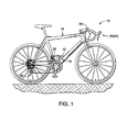
- Figure 1 is a side elevational view of a bicycle having an electrically controlled shifting system in which a battery is mounted to a bicycle frame using a bicycle battery holder in accordance with one preferred embodiment;
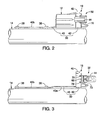
- Figure 2 is a partial side elevational view of the bicycle battery holder illustrated in Figure 1 with the bracket member mounted to the down tube of the bicycle frame and the battery holder assembly at the second battery retaining location (fully seated position);
- Figure 3 is a partial side elevational view, similar to Figure 2 , of the bicycle battery holder illustrated in Figure 1 with the bracket member mounted to the down tube of the bicycle frame and the battery holder removed;
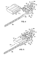
- Figure 4 is a bottom side perspective view of the bicycle battery holder illustrated in Figures 1 to 3 showing installation of the battery onto the battery holder assembly;
- Figure 5 is a bottom side perspective view of the bicycle battery holder illustrated in Figures 1 to 4 showing the battery on the bracket member of the battery holder assembly, but not yet moved to the first battery retaining location;
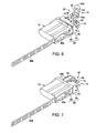
- Figure 6 is a bottom side perspective view of the bicycle battery holder illustrated in Figures 1 to 5 showing the battery on the bracket member of the battery holder assembly at the first battery retaining location (non-fully seated position);
- Figure 7 is a bottom side perspective view of the bicycle battery holder illustrated in Figures 1 to 6 showing the battery on the bracket member of the battery holder assembly at the second battery retaining location (fully seated position);
- Figure 8 is a side perspective view of the bicycle battery holder with the battery positioned for installation into the battery holder assembly illustrated in Figures 1 to 7 ;
- Figure 9 is a side perspective view, similar to Figure 8 , of the bicycle battery holder with the battery at a first battery retaining location with respect to the bicycle battery holder such that the battery is retained to the battery holder assembly, but not in a fully seated position;
- Figure 10 is a side perspective view, similar to Figures 8 and 9 , of the bicycle battery holder with the battery at a second battery retaining location with respect to the bicycle battery holder such that the battery is retained to the battery holder assembly in a fully seated position;
- Figure 11 is an end elevational view of the battery for the bicycle battery holder illustrated in Figures 1 to 10 ;
- Figure 12 is an end elevational view of the bicycle battery holder illustrated in Figures 1 to 10 ;
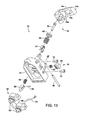
- Figure 13 is an exploded perspective view of the bicycle battery holder illustrated in Figures 1 to 10 ;
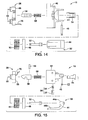
- Figure 14 is an exploded side elevational view of the bicycle battery holder illustrated in Figures 1 to 10 ;
- Figure 15 is an exploded top plan view of the bicycle battery holder illustrated in Figures 1 to 10 ;
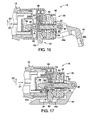
- Figure 16 is a cross-sectional view of the bicycle battery holder taken along the line 16-16 in Figure 9 , showing the battery holder assembly at the first battery retaining location (non-fully seated position);
- Figure 17 is a cross-sectional view of the bicycle battery holder taken along the line 17-17 in Figure 10 , showing the battery holder assembly at the second battery retaining location (fully seated position);
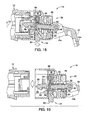
- Figure 18 is a cross-sectional view, similar to Figure 16 , of the bicycle battery holder, but with the release button press to release the battery;
- Figure 19 is a cross-sectional view, similar to Figures 16 and 18 , of the bicycle battery holder, but with the battery detached from the bicycle battery holder;
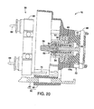
- Figure 20 is a cross-sectional view of the bicycle battery holder taken along the line 20-20 in Figure 12 , but with the terminal block exploded outwardly from the bracket member.
- a bicycle 10 is illustrated that is equipped with an electrically controlled shifting system in which a battery 12 is mounted to a bicycle frame 14 using a bicycle battery holder 16 in accordance with one preferred embodiment.
- the bicycle battery holder 16 is fixedly coupled to the bicycle frame 14 of the bicycle 10 with the battery 12 being easily removed from and reattached to the bicycle battery holder 16 as explained below.
- the electrically controlled shifting system includes a pair of electric shifters 20 and 22, a front motorized derailleur 24, a rear motorized derailleur 26 and a cycle computer 28.
- the electric shifters 20 and 22 can be configured to electronically control positioning of a chain relative to front and rear chain sprockets of the bicycle 10 in a conventional manner.
- control signals from the electric shifters 20 and 22 are transmitted to electric motor units (not shown) in each of the motorized derailleurs 24 and 26 such that a chain guide moves the chain in a conventional manner to the selected chain sprocket. Since the electric motor units of the motorized derailleurs 24 and 26 are electrically powered, a power source is necessary to operate them.
- the battery 12 supplies electrical power to at least motor units (not shown) of the motorized derailleurs 24 and 26.
- the bicycle battery holder 16 is electrically coupled to the motor units (not shown) of the motorized derailleurs 24 and 26 and the battery 12 is electrically coupled to the bicycle battery holder 16 as explained below. Since electric shifters, motorized derailleurs and cycle computers are well know in the bicycle art, the electric shifters 20 and 22, the motorized derailleurs 24 and 26 and the cycle computer 28 will not be discussed or illustrated in detail herein.
- the bicycle battery holder 16 basically includes a stationary mounting structure 30, a battery retaining mechanism 32, a battery release mechanism 34 ( Figure 13 ) and an electrical contact structure 36.
- the stationary mounting structure 30 basically supports the battery 12 on the bicycle frame 14.
- the battery retaining mechanism 32 basically secures the battery 12 to the stationary mounting structure 30 such that the battery 12 can be easily removed from and reattached to the stationary mounting structure 30 as explained below.
- the battery release mechanism 34 basically cooperates with the battery retaining mechanism 32 to release the battery 12 from the stationary mounting structure 30 by moving the battery retaining mechanism 32 out of engagement with the battery 12.
- the electrical contact structure 36 provides stationary contacts for the battery 12 such that the battery 12 can be easily and simultaneously disconnected from the motor units (not shown) of the motorized deraille 24 and 26.
- the stationary mounting structure 30 of the bicycle battery holder 16 is fixedly coupled to the down tube of the bicycle frame 14 by a pair of mounting bolts 38 at the anchoring points that are typically used for attaching a bottle cage to the down tube of the bicycle frame 14.
- the stationary mounting structure 30 basically includes a mounting rail 40 and a bracket member 42.
- the mounting rail 40 is a hard rigid member constructed of a lightweight material such as aluminum or any other suitable material.
- the mounting rail 40 is a one-piece, unitary member that can basically be divided into a bracket connecting section 40a and a frame attachment section 40b.
- the bracket connecting section 40a is shaped to be fixedly coupled with the battery 12 by sliding movement of the battery 12 in a first direction D1 with respect to the bracket member 42.
- the bracket connecting section 40a has two wide sections that mates with a corresponding structure of the battery 12 as discussed below.
- the bracket connecting section 40a is preferably fixedly attached to the bracket member 42 by a pair of fasteners such as screws 43 as seen in Figures 6 and 7 .
- the frame attachment section 40b has a plurality of mounting holes for receiving the mounting bolts 38.
- the bracket member 42 is configured to be fixedly coupled to the bicycle frame 14 by the mounting rail 40 as mentioned above.
- the bracket member 42 has a recess 42a that mates with one end of the battery 12 when the battery 12 is slid along the mounting rail 40.
- the bracket member 42 is a hard rigid member constructed of a lightweight material such as hard plastic or any other suitable material.
- the battery retaining mechanism 32 basically includes a cam lever member 44, a cam axle 46, a main spring holder 48, a main spring 50, a connecting pin 52, a spring cap 54, a hook spring 56, and a hook 58.
- the battery retaining mechanism 32 is supported by the bracket member 42.
- the battery retaining mechanism 32 is configured and arranged with respect to the bracket member 42 for selectively securing the battery 12 to the bracket member 42.
- the battery retaining mechanism 32 and the battery release mechanism 34 cooperate together to provide for quick replacement of the battery 12.
- the battery retaining mechanism 32 provides for a tight coupling between the battery 12 and the bracket member 42 as discussed below.
- the connecting pin 52 and the hook 58 are fixed together by a pin 59 to form an engaging member 60 that retains the battery 12 to the bracket member 42.
- the connecting pin 52 and the hook 58 are both hard rigid members that are preferably formed of a lightweight metal material such as aluminum.
- the engaging member 60 is coupled to the cam lever member 44 by the cam axle 46 for movement in the first direction D1.
- the connecting pin 52 has a hole for pivotally receiving the cam axle 46, which in turn is supported in a pair of slots of the bracket member 42.
- the engaging member 60 is configured and arranged to initially engage and retain the battery 12 by merely sliding the battery 12 in the first direction D 1 with respect to the bracket member 42. After this initial engagement between the battery 12 and the engaging member 60 occurs with the cam lever member 44 in the first lever (open) position, the battery 12 and the engaging member 60 are disposed at a first battery retaining location with respect to the bracket member 24 as seen in Figures 6 , 9 and 16 . In the first battery retaining location, the battery 12 is retained on the bracket member 24 by the engaging member 60.
- the engaging member 60 is moved further in the first direction D1 past the first battery retaining location such that a tight coupling between the battery 12 and the bracket member 42 can then be obtained.
- the engaging member 60 is movably mounted to the bracket member 42 to selectively retain the battery 12 to the bracket member 42 as discussed below.
- the cam lever member 44 is pivotally coupled to the bracket member 42 by the cam axle 46 such that the cam lever member 44 is movable from the first lever (open) position (see Figures 4 to 6 , 8 and 9 ) to the second lever (closed) position (see Figures 7 and 10 ) for moving the engaging member 60 in the first direction D1 as mentioned above.
- the first lever position is basically a free or unlocked position in which the battery release mechanism 34 can be operated to release the battery 12, while the second lever position is basically a locked position in which the battery release mechanism 34 is inaccessible.
- the battery 12 can be retained on the bracket member 42 when the cam lever member 44 is in either the first lever position or the second lever position.
- the cam lever member 44 holds the engaging member 60 at the first battery retaining location with respect to the bracket member 42 such that the battery 12 can be initially installed on the bracket member 42 by moving the battery 12 on the mounting rail 40 in the first direction D1.
- the battery 12 engages the hook 58 of the engaging member 60
- the battery 12 is held at the first battery retaining location on the bracket member 42.
- the cam lever member 44 is moved to the second lever (closed) position
- the engaging member 60 is moved further in the first direction D1 past the first battery retaining location such that a tight coupling between the battery 12 and the bracket member 42 is obtained.
- the battery retaining mechanism 32 is configured and arranged such that even if the cam lever member 44 is moved to the first lever (open) position unintentionally, the hook 58 prevents the battery 12 from coming off of the bracket member 42.
- the cam lever member 44 includes a cam portion 44a and a lever portion 44b with a release button receiving recess 44c in the lever portion 44b.
- the cam portion 44a is operatively engages the bracket member 24 via the main spring holder 48 and the main spring 50 to move the engaging member 60 in the first direction D1 when the cam lever member 44 is moved from the first lever position to the second lever position.
- the cam lever member 44 is moved from the first lever position to the second lever position, the cam portion 44a contacts the main spring holder 48 and compresses the main spring 50 as the cam lever member 44 pulls the engaging member 60 in the first direction D 1 with respect to the bracket member 42.
- the cam portion 44a cooperates with the main spring holder 48 and the main spring 50 to pull the engaging member 60 in the first direction D1 with respect to the bracket member 42.
- the cam portion 44a is also configured and arranged to be held in the second lever position by the urging force of the main spring 50.
- the cam portion 44a is configured and arranged to have an over-the-center type of arrangement with respect to the cam axle 46 such that the urging force of the main spring 50 is located on one side of the cam axle 46 to push the cam lever member 44 towards the first lever (open) position prior to the cam lever member 44 reaching the second lever position and such that the urging force of the main spring 50 is located on the other side of the cam axle 46 to push the cam lever member 44 towards the second lever (closed) position.
- the main spring holder 48 is a rigid cap shaped member with a hole through the end surface so that the connecting pin 52 can pass therethrough.
- the main spring holder 48 covers one end of the main spring 50 and acts as a contact surface for the cam portion 44a of the cam lever member 44.
- the main spring 50 is a compression spring which disposed between the main spring holder 48 and an end surface of the bracket member 42. The main spring holder 48 and the main spring 50 cooperate together to operatively transmit an urging force between the bracket member 42 and the cam lever member 44.
- the spring cap 54 and the hook spring 56 cooperate together to operatively transmit an urging force between the bracket member 42 and the cam lever member 44 via the engaging member 60.
- the spring cap 54 and the hook spring 56 are concentrically mounted on the connecting pin 52 with the hook spring 56 operatively disposed between the spring cap 54 and the hook 58.
- the spring cap 54 has one end fixed to the bracket member 42 and the other end supporting the hook spring 56.
- the hook spring 56 is compressed by the movement of the engaging member 60 in the first direction D1.
- the battery release mechanism 34 includes a release button 62 and a return spring 64.
- the release button 62 is movably mounted to the bracket member 42 against an urging force of the return spring 64.
- the return spring 64 is disposed between the bracket member 42 and the hook 58 to bias the engaging member 60 against an inner end of the release button 62.
- the return spring 64 holds the engaging member 60 and the release button 62 in rest positions such that the engaging member 60 is located along the center plane of the bracket member 42 and the release button 62 protrudes out of the bracket member 42.
- the release button 62 is operatively coupled to the engaging member 60 to move the engaging member 60 to a battery release position ( Figure 18 ) when the release button 62 is moved from a first button (rest) position ( Figure 16 ) to a second button (depressed) position ( Figure 18 ).
- the release button 62 is depressed against the urging force of the return spring 64, the hook 58 is moved laterally to the battery release position.
- the lateral movement of the release button 62 in a transverse direction D2 also moves the engaging member 60 in the transverse direction D2.
- This lateral movement of the release button 62 and the engaging member 60 in the transverse direction D2 causes the engaging member 60 to move out of engagement from the battery 12 when the engaging member and the battery are in the first battery retaining location.
- the battery 12 when the battery 12 is inserted in to the recess 42a of the bracket member 42, the battery 12 initially contacts the hook 58 to move the hook 58 laterally to the battery release position against the urging force of the return spring 64 and then the hook 58 moves laterally back to the rest position for retaining the battery 12 to the bracket member 42 in the first battery retaining location as seen in Figure 16 .
- the cam lever member 44 can be rotated to the second lever (closed) position (see Figures 7 , 10 and 17 ) so that the engaging member 60 is moved in the first direction D1 to pull the battery 12 to the second battery retaining location as seen in Figure 17 .
- the lever portion 44b covers the release button 62 such that the release button 62 is disposed in the release button receiving recess 44c in the lever portion 44b.
- the release button 62 is inaccessible.
- the electrical contact structure 36 basically includes a terminal block 66 with a pair of electrical (terminals) contacts 68 and an electrical wire 70.
- the electrical contacts 68 are embedded in the terminal block 66. As shown in Figures 12 and 13 , the electrical contacts 68 extend from the terminal block 66 in a direction generally parallel to one another. The electrical contacts 68 are also generally parallel to the mounting rail 40 as seen in Figure 20 .
- the electrical contacts 68 are configured to extend into corresponding terminal receiving portions of the battery 12, as described below.
- the electrical contacts 68 are each electrically connected to one electrical conductor of the electrical wire 70 to transfer electrical power from the battery to the deraille 24 and 26.
- the terminal block 66 is formed of a substantially rigid plastic material with tubular portions (annular ring-like shape) concentrically arranged around the electrical contacts 68. These tubular portions of the terminal block 66 are thin walled portions with a sufficient amount of resiliency to act as sealing members.
- the terminal block 66 is secured to the bracket member 42 by a pair of bolts 72.
- the battery 12 is a replaceable battery pack.
- the battery 12 can be a rechargeable battery that is rechargeable by the electricity generating device mounted to the bicycle 10.
- the battery 12 has an end face that includes a pair of apertures 80 with each of the apertures 80 having a contact receiving bore 82.
- the apertures 80 and the contact receiving bores 82 are configured to receive the tubular portions of the terminal block 66 and the electrical contacts 68, respectively.
- the end face of the battery 12 also has a hook receiving recess 84 with a latch surface 86.
- the bottom surface of the battery 12 has a slot 88 formed by a pair of flanges with cutouts for receiving the bracket connecting section 40a of the mounting rail 40. Since batteries are conventional electronic components, further description of the battery 12 is omitted for the sake of brevity.
- the hook receiving recess 84 with the latch surface 86 of the battery 12 constitutes a latch portion of the battery 12.
- the hook 58 initially contacts the opening edge of the hook receiving recess 84 when the battery 12 is being moved along the mounting rail 40 to the first battery retaining location such that the hook 58 moves laterally to the battery release position against the urging force of the return spring 64.
- the engaging member 60 is moved in the transverse direction D2 against the force of the return spring 64 during initial insertion of the battery 12 into the bracket member 42.
- the engaging member 60 is urged back to its rest position by the force of the return spring 64 such that the hook 58 engaged the latch surface 86 within the hook receiving recess 84 of the battery 12.
- the hook 58 of the engaging member 60 engage the latch surface 86 of the latch portion of the battery 12 prior to the cam lever member 44 being moved to the second lever position.
- the engaging member 60 is arranged with respect to the bracket member 42 to be automatically moved in the transverse direction D2 with respect to the first direction D1 in response to movement of the battery 12 in the first direction D1 to the first battery retaining location.
- movement of the battery is limited to a small amount of back and forward movement in the longitudinal direction.
- the battery 12 is retained on the bracket member 42 in the first battery retaining location.
- Rotation of the cam lever member 44 to the second lever (closed) position causes the engaging member 60 is moved further in the first direction D1 past the first battery retaining location such that a tight coupling between the battery 12 and the bracket member 42 is obtained.
Landscapes
- Engineering & Computer Science (AREA)
- Mechanical Engineering (AREA)
- Chemical & Material Sciences (AREA)
- Combustion & Propulsion (AREA)
- Transportation (AREA)
- Battery Mounting, Suspending (AREA)
Abstract
Description
- This invention generally relates to a bicycle battery holder. More specifically, the present invention relates to bicycle battery holder in which the battery can be easily installed and removed. Background Information
- Bicycling is becoming an increasingly more popular form of recreation as well as a means of transportation. Moreover, bicycling has become a very popular competitive sport for both amateurs and professionals. Whether the bicycle is used for recreation, transportation or competition, the bicycle industry is constantly improving the various components of the bicycle.
- Recently, bicycles have been equipped with electrical components to make riding easier and more enjoyable for the rider. Some bicycles are equipped with electrically controlled shifting systems. Such systems require electricity from a power source, such as a wheel hub generator and/or a battery. In cases where a battery is used as a power source, a mounting structure must be provided to attach the battery to the bicycle frame. Preferably, the mounting structure is configured such that the battery can be easily installed and removed. One example of a battery holder is disclosed in
U.S. Patent No. 7,267,352 in which a stopper assembly is used to retain a battery unit on the mounting unit, which is attached to a seat tube of the bicycle frame. Another example of a battery holder is disclosed inU.S. Patent No. 6,669,220 in which an integrated control and power unit has a battery holder which is attached to a down tube of the bicycle frame. While the battery holders of both of these patents work well, they have certain drawbacks. For example, inU.S. Patent No. 7,267,352 , the stopper assembly can be difficult for some riders to operate with one hand. The battery holder ofU.S. Patent No. 6,669,220 is merely held in place by a press fit such that the battery may accidentally fall out while riding over rough terrain. - In view of the above, it will be apparent to those skilled in the art from this disclosure that there exists a need for an improved battery holder. This invention addresses this need in the art as well as other needs, which will become apparent to those skilled in the art from this disclosure.
- One object of the present invention is to provide a bicycle battery holder in which the battery can be easily installed and removed.
- The foregoing objects can basically be attained by providing a bicycle battery holder for retaining a battery in which the bicycle battery holder basically comprises a battery, a bracket member, an engaging member and a lever member. The engaging member is movably mounted to the bracket member and configured to selectively retain the battery to the bracket member. The lever member is movably mounted to the bracket member and operatively coupled to the engaging member to move the engaging member in a first direction with respect to the bracket member when the lever member is moved from a first lever position to a second lever position.
- These and other objects, features, aspects and advantages of the present invention will become apparent to those skilled in the art from the following detailed description, which, taken in conjunction with the annexed drawings, discloses a preferred embodiment of the present invention.
- Referring now to the attached drawings which form a part of this original disclosure:
-
Figure 1 is a side elevational view of a bicycle having an electrically controlled shifting system in which a battery is mounted to a bicycle frame using a bicycle battery holder in accordance with one preferred embodiment; -
Figure 2 is a partial side elevational view of the bicycle battery holder illustrated inFigure 1 with the bracket member mounted to the down tube of the bicycle frame and the battery holder assembly at the second battery retaining location (fully seated position); -
Figure 3 is a partial side elevational view, similar toFigure 2 , of the bicycle battery holder illustrated inFigure 1 with the bracket member mounted to the down tube of the bicycle frame and the battery holder removed; -
Figure 4 is a bottom side perspective view of the bicycle battery holder illustrated inFigures 1 to 3 showing installation of the battery onto the battery holder assembly; -
Figure 5 is a bottom side perspective view of the bicycle battery holder illustrated inFigures 1 to 4 showing the battery on the bracket member of the battery holder assembly, but not yet moved to the first battery retaining location; -
Figure 6 is a bottom side perspective view of the bicycle battery holder illustrated inFigures 1 to 5 showing the battery on the bracket member of the battery holder assembly at the first battery retaining location (non-fully seated position); -
Figure 7 is a bottom side perspective view of the bicycle battery holder illustrated inFigures 1 to 6 showing the battery on the bracket member of the battery holder assembly at the second battery retaining location (fully seated position); -
Figure 8 is a side perspective view of the bicycle battery holder with the battery positioned for installation into the battery holder assembly illustrated inFigures 1 to 7 ; -
Figure 9 is a side perspective view, similar toFigure 8 , of the bicycle battery holder with the battery at a first battery retaining location with respect to the bicycle battery holder such that the battery is retained to the battery holder assembly, but not in a fully seated position; -
Figure 10 is a side perspective view, similar toFigures 8 and 9 , of the bicycle battery holder with the battery at a second battery retaining location with respect to the bicycle battery holder such that the battery is retained to the battery holder assembly in a fully seated position; -
Figure 11 is an end elevational view of the battery for the bicycle battery holder illustrated inFigures 1 to 10 ; -
Figure 12 is an end elevational view of the bicycle battery holder illustrated inFigures 1 to 10 ; -
Figure 13 is an exploded perspective view of the bicycle battery holder illustrated inFigures 1 to 10 ; -
Figure 14 is an exploded side elevational view of the bicycle battery holder illustrated inFigures 1 to 10 ; -
Figure 15 is an exploded top plan view of the bicycle battery holder illustrated inFigures 1 to 10 ; -
Figure 16 is a cross-sectional view of the bicycle battery holder taken along the line 16-16 inFigure 9 , showing the battery holder assembly at the first battery retaining location (non-fully seated position); -
Figure 17 is a cross-sectional view of the bicycle battery holder taken along the line 17-17 inFigure 10 , showing the battery holder assembly at the second battery retaining location (fully seated position); -
Figure 18 is a cross-sectional view, similar toFigure 16 , of the bicycle battery holder, but with the release button press to release the battery; -
Figure 19 is a cross-sectional view, similar toFigures 16 and18 , of the bicycle battery holder, but with the battery detached from the bicycle battery holder; and -
Figure 20 is a cross-sectional view of the bicycle battery holder taken along the line 20-20 inFigure 12 , but with the terminal block exploded outwardly from the bracket member. - Selected embodiments of the present invention will now be explained with reference to the drawings. It will be apparent to those skilled in the art from this disclosure that the following descriptions of the embodiments of the present invention are provided for illustration only and not for the purpose of limiting the invention as defined by the appended claims and their equivalents.
- Referring initially to
Figures 1 to 3 , abicycle 10 is illustrated that is equipped with an electrically controlled shifting system in which abattery 12 is mounted to abicycle frame 14 using abicycle battery holder 16 in accordance with one preferred embodiment. As best seen inFigures 2 and 3 , thebicycle battery holder 16 is fixedly coupled to thebicycle frame 14 of thebicycle 10 with thebattery 12 being easily removed from and reattached to thebicycle battery holder 16 as explained below. - Basically, as seen in
Figure 1 , the electrically controlled shifting system includes a pair ofelectric shifters derailleur 24, a rear motorizedderailleur 26 and acycle computer 28. Theelectric shifters bicycle 10 in a conventional manner. Specifically, control signals from theelectric shifters motorized derailleurs motorized derailleurs battery 12 supplies electrical power to at least motor units (not shown) of themotorized derailleurs bicycle battery holder 16 is electrically coupled to the motor units (not shown) of themotorized derailleurs battery 12 is electrically coupled to thebicycle battery holder 16 as explained below. Since electric shifters, motorized derailleurs and cycle computers are well know in the bicycle art, theelectric shifters motorized derailleurs cycle computer 28 will not be discussed or illustrated in detail herein. - Referring now to
Figures 4 to 10 and13 , thebicycle battery holder 16 basically includes astationary mounting structure 30, abattery retaining mechanism 32, a battery release mechanism 34 (Figure 13 ) and anelectrical contact structure 36. Thestationary mounting structure 30 basically supports thebattery 12 on thebicycle frame 14. Thebattery retaining mechanism 32 basically secures thebattery 12 to thestationary mounting structure 30 such that thebattery 12 can be easily removed from and reattached to thestationary mounting structure 30 as explained below.. Thebattery release mechanism 34 basically cooperates with thebattery retaining mechanism 32 to release thebattery 12 from thestationary mounting structure 30 by moving thebattery retaining mechanism 32 out of engagement with thebattery 12. Theelectrical contact structure 36 provides stationary contacts for thebattery 12 such that thebattery 12 can be easily and simultaneously disconnected from the motor units (not shown) of themotorized derailleurs - As best seen in
Figures 2 and 3 , thestationary mounting structure 30 of thebicycle battery holder 16 is fixedly coupled to the down tube of thebicycle frame 14 by a pair ofmounting bolts 38 at the anchoring points that are typically used for attaching a bottle cage to the down tube of thebicycle frame 14. Thestationary mounting structure 30 basically includes a mountingrail 40 and abracket member 42. - The mounting
rail 40 is a hard rigid member constructed of a lightweight material such as aluminum or any other suitable material. The mountingrail 40 is a one-piece, unitary member that can basically be divided into abracket connecting section 40a and aframe attachment section 40b. Thebracket connecting section 40a is shaped to be fixedly coupled with thebattery 12 by sliding movement of thebattery 12 in a first direction D1 with respect to thebracket member 42. Preferably, thebracket connecting section 40a has two wide sections that mates with a corresponding structure of thebattery 12 as discussed below. Thebracket connecting section 40a is preferably fixedly attached to thebracket member 42 by a pair of fasteners such asscrews 43 as seen inFigures 6 and 7 . Theframe attachment section 40b has a plurality of mounting holes for receiving the mountingbolts 38. - The
bracket member 42 is configured to be fixedly coupled to thebicycle frame 14 by the mountingrail 40 as mentioned above. Thebracket member 42 has arecess 42a that mates with one end of thebattery 12 when thebattery 12 is slid along the mountingrail 40. Thebracket member 42 is a hard rigid member constructed of a lightweight material such as hard plastic or any other suitable material. - As best seen in
Figures 13 to 15 , thebattery retaining mechanism 32 basically includes acam lever member 44, acam axle 46, amain spring holder 48, amain spring 50, a connectingpin 52, aspring cap 54, ahook spring 56, and ahook 58. Thebattery retaining mechanism 32 is supported by thebracket member 42. Thebattery retaining mechanism 32 is configured and arranged with respect to thebracket member 42 for selectively securing thebattery 12 to thebracket member 42. In the illustrated embodiment, thebattery retaining mechanism 32 and thebattery release mechanism 34 cooperate together to provide for quick replacement of thebattery 12. Moreover, in the illustrated embodiment, thebattery retaining mechanism 32 provides for a tight coupling between thebattery 12 and thebracket member 42 as discussed below. - As seen in
Figures 16 to 20 , the connectingpin 52 and thehook 58 are fixed together by apin 59 to form an engagingmember 60 that retains thebattery 12 to thebracket member 42. The connectingpin 52 and thehook 58 are both hard rigid members that are preferably formed of a lightweight metal material such as aluminum. Basically, the engagingmember 60 is coupled to thecam lever member 44 by thecam axle 46 for movement in the first direction D1. In particular, the connectingpin 52 has a hole for pivotally receiving thecam axle 46, which in turn is supported in a pair of slots of thebracket member 42. - When the
cam lever member 44 is in a first lever (open) position, as seen inFigure 16 , the engagingmember 60 is configured and arranged to initially engage and retain thebattery 12 by merely sliding thebattery 12 in the first direction D 1 with respect to thebracket member 42. After this initial engagement between thebattery 12 and the engagingmember 60 occurs with thecam lever member 44 in the first lever (open) position, thebattery 12 and the engagingmember 60 are disposed at a first battery retaining location with respect to thebracket member 24 as seen inFigures 6 ,9 and16 . In the first battery retaining location, thebattery 12 is retained on thebracket member 24 by the engagingmember 60. By rotating thecam lever member 44 from the first lever (open) position (Figure 16 ) to a second lever (closed) position (Figure 17 ), the engagingmember 60 is moved further in the first direction D1 past the first battery retaining location such that a tight coupling between thebattery 12 and thebracket member 42 can then be obtained. Thus, the engagingmember 60 is movably mounted to thebracket member 42 to selectively retain thebattery 12 to thebracket member 42 as discussed below. - Referring back to
Figures 4 to 10 , thecam lever member 44 is pivotally coupled to thebracket member 42 by thecam axle 46 such that thecam lever member 44 is movable from the first lever (open) position (seeFigures 4 to 6 ,8 and 9 ) to the second lever (closed) position (seeFigures 7 and10 ) for moving the engagingmember 60 in the first direction D1 as mentioned above. The first lever position is basically a free or unlocked position in which thebattery release mechanism 34 can be operated to release thebattery 12, while the second lever position is basically a locked position in which thebattery release mechanism 34 is inaccessible. - The
battery 12 can be retained on thebracket member 42 when thecam lever member 44 is in either the first lever position or the second lever position. In the first lever position, thecam lever member 44 holds the engagingmember 60 at the first battery retaining location with respect to thebracket member 42 such that thebattery 12 can be initially installed on thebracket member 42 by moving thebattery 12 on the mountingrail 40 in the first direction D1. When thebattery 12 engages thehook 58 of the engagingmember 60, thebattery 12 is held at the first battery retaining location on thebracket member 42. When thecam lever member 44 is moved to the second lever (closed) position, the engagingmember 60 is moved further in the first direction D1 past the first battery retaining location such that a tight coupling between thebattery 12 and thebracket member 42 is obtained. Thus, thebattery retaining mechanism 32 is configured and arranged such that even if thecam lever member 44 is moved to the first lever (open) position unintentionally, thehook 58 prevents thebattery 12 from coming off of thebracket member 42. - The
cam lever member 44 includes acam portion 44a and alever portion 44b with a releasebutton receiving recess 44c in thelever portion 44b. Thecam portion 44a is operatively engages thebracket member 24 via themain spring holder 48 and themain spring 50 to move the engagingmember 60 in the first direction D1 when thecam lever member 44 is moved from the first lever position to the second lever position. In particular, thecam lever member 44 is moved from the first lever position to the second lever position, thecam portion 44a contacts themain spring holder 48 and compresses themain spring 50 as thecam lever member 44 pulls the engagingmember 60 in the first direction D 1 with respect to thebracket member 42. Thus, thecam portion 44a cooperates with themain spring holder 48 and themain spring 50 to pull the engagingmember 60 in the first direction D1 with respect to thebracket member 42. Thecam portion 44a is also configured and arranged to be held in the second lever position by the urging force of themain spring 50. In particular, thecam portion 44a is configured and arranged to have an over-the-center type of arrangement with respect to thecam axle 46 such that the urging force of themain spring 50 is located on one side of thecam axle 46 to push thecam lever member 44 towards the first lever (open) position prior to thecam lever member 44 reaching the second lever position and such that the urging force of themain spring 50 is located on the other side of thecam axle 46 to push thecam lever member 44 towards the second lever (closed) position. - The
main spring holder 48 is a rigid cap shaped member with a hole through the end surface so that the connectingpin 52 can pass therethrough. Themain spring holder 48 covers one end of themain spring 50 and acts as a contact surface for thecam portion 44a of thecam lever member 44. Themain spring 50 is a compression spring which disposed between themain spring holder 48 and an end surface of thebracket member 42. Themain spring holder 48 and themain spring 50 cooperate together to operatively transmit an urging force between thebracket member 42 and thecam lever member 44. - The
spring cap 54 and thehook spring 56 cooperate together to operatively transmit an urging force between thebracket member 42 and thecam lever member 44 via the engagingmember 60. Thespring cap 54 and thehook spring 56 are concentrically mounted on the connectingpin 52 with thehook spring 56 operatively disposed between thespring cap 54 and thehook 58. As seen inFigure 20 , thespring cap 54 has one end fixed to thebracket member 42 and the other end supporting thehook spring 56. As seen inFigure 17 , when thecam lever member 44 is rotated to the second lever (closed) position, thehook spring 56 is compressed by the movement of the engagingmember 60 in the first direction D1. - Referring now to
Figures 13 ,16 and 17 , thebattery release mechanism 34 will now be described. Basically, thebattery release mechanism 34 includes arelease button 62 and areturn spring 64. Therelease button 62 is movably mounted to thebracket member 42 against an urging force of thereturn spring 64. In particular, thereturn spring 64 is disposed between thebracket member 42 and thehook 58 to bias the engagingmember 60 against an inner end of therelease button 62. In other words, thereturn spring 64 holds the engagingmember 60 and therelease button 62 in rest positions such that the engagingmember 60 is located along the center plane of thebracket member 42 and therelease button 62 protrudes out of thebracket member 42. - As seen in
Figures 16 and18 , therelease button 62 is operatively coupled to the engagingmember 60 to move the engagingmember 60 to a battery release position (Figure 18 ) when therelease button 62 is moved from a first button (rest) position (Figure 16 ) to a second button (depressed) position (Figure 18 ). Thus, when therelease button 62 is depressed against the urging force of thereturn spring 64, thehook 58 is moved laterally to the battery release position. In other words, when the engagingmember 60 is engaged with thebattery 12 while in the first battery retaining location (i.e., the cam lever is in the first lever (open) position), the lateral movement of therelease button 62 in a transverse direction D2 also moves the engagingmember 60 in the transverse direction D2. This lateral movement of therelease button 62 and the engagingmember 60 in the transverse direction D2 causes the engagingmember 60 to move out of engagement from thebattery 12 when the engaging member and the battery are in the first battery retaining location. - Moreover, when the
battery 12 is inserted in to therecess 42a of thebracket member 42, thebattery 12 initially contacts thehook 58 to move thehook 58 laterally to the battery release position against the urging force of thereturn spring 64 and then thehook 58 moves laterally back to the rest position for retaining thebattery 12 to thebracket member 42 in the first battery retaining location as seen inFigure 16 . Now, thecam lever member 44 can be rotated to the second lever (closed) position (seeFigures 7 ,10 and17 ) so that the engagingmember 60 is moved in the first direction D1 to pull thebattery 12 to the second battery retaining location as seen inFigure 17 . When thecam lever member 44 is in the second lever (closed) position (seeFigures 7 ,10 and17 ), thelever portion 44b covers therelease button 62 such that therelease button 62 is disposed in the releasebutton receiving recess 44c in thelever portion 44b. Thus, while thecam lever member 44 is in the second lever (closed) position, therelease button 62 is inaccessible. - The
electrical contact structure 36 basically includes aterminal block 66 with a pair of electrical (terminals)contacts 68 and anelectrical wire 70. Theelectrical contacts 68 are embedded in theterminal block 66. As shown inFigures 12 and13 , theelectrical contacts 68 extend from theterminal block 66 in a direction generally parallel to one another. Theelectrical contacts 68 are also generally parallel to the mountingrail 40 as seen inFigure 20 . Theelectrical contacts 68 are configured to extend into corresponding terminal receiving portions of thebattery 12, as described below. Theelectrical contacts 68 are each electrically connected to one electrical conductor of theelectrical wire 70 to transfer electrical power from the battery to thederailleurs terminal block 66 is formed of a substantially rigid plastic material with tubular portions (annular ring-like shape) concentrically arranged around theelectrical contacts 68. These tubular portions of theterminal block 66 are thin walled portions with a sufficient amount of resiliency to act as sealing members. Theterminal block 66 is secured to thebracket member 42 by a pair ofbolts 72. - The
battery 12 is a replaceable battery pack. Alternatively, thebattery 12 can be a rechargeable battery that is rechargeable by the electricity generating device mounted to thebicycle 10. As seen inFigure 11 , thebattery 12 has an end face that includes a pair ofapertures 80 with each of theapertures 80 having a contact receiving bore 82. Theapertures 80 and the contact receiving bores 82 are configured to receive the tubular portions of theterminal block 66 and theelectrical contacts 68, respectively. The end face of thebattery 12 also has ahook receiving recess 84 with alatch surface 86. As best seen inFigure 4 , the bottom surface of thebattery 12 has aslot 88 formed by a pair of flanges with cutouts for receiving thebracket connecting section 40a of the mountingrail 40. Since batteries are conventional electronic components, further description of thebattery 12 is omitted for the sake of brevity. - The
hook receiving recess 84 with thelatch surface 86 of thebattery 12 constitutes a latch portion of thebattery 12. Thehook 58 initially contacts the opening edge of thehook receiving recess 84 when thebattery 12 is being moved along the mountingrail 40 to the first battery retaining location such that thehook 58 moves laterally to the battery release position against the urging force of thereturn spring 64. Thus, the engagingmember 60 is moved in the transverse direction D2 against the force of thereturn spring 64 during initial insertion of thebattery 12 into thebracket member 42. Once thebattery 12 reaches the first battery retaining location, the engagingmember 60 is urged back to its rest position by the force of thereturn spring 64 such that thehook 58 engaged thelatch surface 86 within thehook receiving recess 84 of thebattery 12. In other words, thehook 58 of the engagingmember 60 engage thelatch surface 86 of the latch portion of thebattery 12 prior to thecam lever member 44 being moved to the second lever position. Moreover, with this arrangement of the illustrated embodiment, the engagingmember 60 is arranged with respect to thebracket member 42 to be automatically moved in the transverse direction D2 with respect to the first direction D1 in response to movement of thebattery 12 in the first direction D1 to the first battery retaining location. Also with the mating connection between thebracket connecting section 40a and theslot 88 of thebattery 12, movement of the battery is limited to a small amount of back and forward movement in the longitudinal direction. Now thebattery 12 is retained on thebracket member 42 in the first battery retaining location. Rotation of thecam lever member 44 to the second lever (closed) position causes the engagingmember 60 is moved further in the first direction D1 past the first battery retaining location such that a tight coupling between thebattery 12 and thebracket member 42 is obtained. - In understanding the scope of the present invention, the term "comprising" and its derivatives, as used herein, are intended to be open ended terms that specify the presence of the stated features, elements, components, groups, integers, and/or steps, but do not exclude the presence of other unstated features, elements, components, groups, integers and/or steps. The foregoing also applies to words having similar meanings such as the terms, "including", "having" and their derivatives. Also, the terms "part," "section," "portion," "member" or "element" when used in the singular can have the dual meaning of a single part or a plurality of parts. Finally, terms of degree such as "substantially", "about" and "approximately" as used herein mean a reasonable amount of deviation of the modified term such that the end result is not significantly changed.
- While only selected embodiments have been chosen to illustrate the present invention, it will be apparent to those skilled in the art from this disclosure that various changes and modifications can be made herein without departing from the scope of the invention as defined in the appended claims. Furthermore, the foregoing descriptions of the embodiments according to the present invention are provided for illustration only, and not for the purpose of limiting the invention as defined by the appended claims and their equivalents.
Claims (15)
- A bicycle battery holder (16) for retaining a battery (12) comprising:a bracket member (42);an engaging member (60) movably mounted to the bracket member (42) and configured to selectively retain the battery to the bracket member (42); anda lever member (44) movably mounted to the bracket member (42) and operatively coupled to the engaging member (60) to move the engaging member (60) in a first direction (D1) with respect to the bracket member (42) when the lever member (44) is moved from a first lever position to a second lever position.
- The bicycle battery holder according to claim 1, characterized in that
the lever member (44) includes a cam portion (44a) that operatively engages the bracket member (42) to move the engaging member (60) in the first direction (D1) when the lever member (44) is moved from the first lever position to the second lever position. - The bicycle battery holder according to an of the claims 1 or 2, characterized in that
the engaging member (60) includes a hook (58) that is configured to engage a latch portion (84) of the battery (12) prior to the lever member (44) being moved to the second lever position. - The bicycle battery holder according to any of the claims 1 to 3 characterized in that
the bracket member (42) and the engaging member (60) are configured to engage the battery (12) by sliding movement of the battery (12) in the first direction (D1) with respect to the bracket member (42). - The bicycle battery holder according to any of the claims 1 to 4, characterized in that
the engaging member (60) is movably mounted to the bracket member (42) to move in a transverse direction with respect to the first direction and to engage the battery (12) when the battery (12) is at a first battery retaining location with respect to the bracket member (42). - The bicycle battery holder according to claim 5, characterized in that
the engaging member (60) is arranged with respect to the bracket member (42) to be moved in the transverse direction (D12 in response to movement of the battery (12) in the first direction (D1) to the first battery retaining location. - The bicycle battery holder according to any of the claims 1 to 6, characterized in that it further comprises
a release button (62) movably mounted to the bracket member (42) and operatively coupled to the engaging member (60) to move the engaging member (60) to a battery release position when the release button (62) is moved from a first button position to a second button position. - The bicycle battery holder according to claim 7, characterized in that
the lever member (44) is arranged with respect to the release button (62) such that the release button (62) is inaccessible with the lever member (44) in the second lever position and accessible with the lever member (44) in the first lever position. - A bicycle battery holder (16) for retaining a battery (12) comprising:a bracket member (42) configured to be coupled to the battery (12) by movement of the battery (12) in a first direction (D1) with respect to the bracket member (42); andan engaging member (60) movably mounted to the bracket (42) member to move in a transverse direction (D2) with respect to the first direction (D1) and to engage the battery (12) when the battery (12) is at a first battery retaining location with respect to the bracket member (42),the battery (12) being further movable in the first direction past the first battery retaining location to a second battery retaining location.
- The bicycle battery holder according to claim 9, characterized in that
the engaging member (60) includes a hook (58) that is arranged with respect to the bracket member (42) to engage a latch portion (84) of the battery (12). - The bicycle battery holder according to any of the claims 9 or 10, characterized in that
the engaging member (60) is arranged with respect to the bracket member (42) to be moved in the transverse direction (D2) in response to movement of the battery in the first direction (D1) to the first battery retaining location. - The bicycle battery holder according to any of the claims 9 to 11, characterized in that
the bracket (42) member and the engaging member (60) are configured to engage the battery by sliding movement of the battery (12) in the first direction (D1) with respect to the bracket member (42). - The bicycle battery holder according to any of the claims 9 to 12, characterized in that it further comprises
a lever member (44) movably mounted to the bracket member (42) and operatively coupled to the engaging member (60) to move the engaging member (60) in the first direction (D1) from the first battery retaining location to the second battery retaining location when the lever member (44) is moved from a first lever position to a second lever position. - The bicycle battery holder according to any of the claims 9 to 13, characterized in that
the lever member (44) includes a cam portion (44a) that operatively engages the bracket member (44) to move the engaging member (60) in the first direction (D1) when the lever member (44) is moved from the first lever position to the second lever position. - The bicycle battery holder according to any of the claims 9 to 14, characterized in that it further comprises
a release button movably mounted to the bracket member and operatively coupled to the engaging member (60) to move the engaging member (60) to a battery release position when the release button is moved from a first button position to a second button position.
Applications Claiming Priority (1)
| Application Number | Priority Date | Filing Date | Title |
|---|---|---|---|
| US12/106,587 US8162191B2 (en) | 2008-04-21 | 2008-04-21 | Bicycle battery holder |
Publications (3)
| Publication Number | Publication Date |
|---|---|
| EP2112060A2 true EP2112060A2 (en) | 2009-10-28 |
| EP2112060A3 EP2112060A3 (en) | 2012-12-05 |
| EP2112060B1 EP2112060B1 (en) | 2016-08-31 |
Family
ID=40847897
Family Applications (1)
| Application Number | Title | Priority Date | Filing Date |
|---|---|---|---|
| EP09151610.4A Active EP2112060B1 (en) | 2008-04-21 | 2009-01-29 | Bicycle battery holder |
Country Status (4)
| Country | Link |
|---|---|
| US (1) | US8162191B2 (en) |
| EP (1) | EP2112060B1 (en) |
| CN (1) | CN101565069B (en) |
| TW (1) | TWI383914B (en) |
Cited By (8)
| Publication number | Priority date | Publication date | Assignee | Title |
|---|---|---|---|---|
| EP2722266A1 (en) * | 2012-10-18 | 2014-04-23 | Sram, Llc. | Front gear changer |
| EP2626233A3 (en) * | 2012-02-09 | 2015-03-11 | Honda Motor Co., Ltd. | Terminal base of power supply device for electric vehicle |
| EP2988345A1 (en) * | 2014-08-21 | 2016-02-24 | Modern Times Ltd. | Battery assembly for fitting a battery pack to a frame of a cycle |
| EP3118096A1 (en) * | 2015-07-16 | 2017-01-18 | ZEG Zweirad-Einkaufs-Genossenschaft eG | Bicycle frame, energy supply unit therefor and electric bicycle for same |
| DE102021207470A1 (en) | 2021-07-14 | 2023-01-19 | Zf Friedrichshafen Ag | Fixing an energy store on a vehicle frame with a lever |
| IT202100024716A1 (en) * | 2021-09-28 | 2023-03-28 | Campagnolo Srl | BICYCLE EQUIPMENT EQUIPPED WITH ELECTRIC POWER SUPPLY UNIT |
| DE102021212301A1 (en) | 2021-11-02 | 2023-05-04 | Zf Friedrichshafen Ag | Adapter for attaching to an energy store, energy store, coupling unit, system for coupling an energy store |
| EP4176148A4 (en) * | 2020-07-03 | 2023-12-20 | Revonte Oy | BATTERY SUPPORT AND BATTERY SUPPORT ARRANGEMENT FOR LIGHT ELECTRIC VEHICLE |
Families Citing this family (31)
| Publication number | Priority date | Publication date | Assignee | Title |
|---|---|---|---|---|
| US8413947B2 (en) * | 2010-11-12 | 2013-04-09 | Joy Industrial Co., Ltd. | Positioning device for battery box |
| EP2532571B1 (en) * | 2011-06-10 | 2014-03-26 | Campagnolo S.r.l. | Bicycle on-board device and related mounting method |
| US8893837B2 (en) * | 2011-06-14 | 2014-11-25 | Samsung Sdi Co., Ltd. | Battery pack storing device and electric vehicle including the same |
| US9399499B2 (en) * | 2011-06-29 | 2016-07-26 | Shimano Inc. | Bicycle battery holder |
| US9174691B2 (en) * | 2011-07-21 | 2015-11-03 | Dan Goldwater | Universal mount battery holder for bicycles |
| JP2013122816A (en) | 2011-12-09 | 2013-06-20 | Shimano Inc | Holder, electric power assembly including holder, and power storage member held by holder |
| US9085342B2 (en) * | 2012-03-03 | 2015-07-21 | Dr. Nathan Jauvtis Engineering | Power assisted vehicle |
| US9434445B1 (en) * | 2012-03-03 | 2016-09-06 | Dr. Nathan Jauvtis Engineering | Electronic bicycle |
| US9394030B2 (en) * | 2012-09-27 | 2016-07-19 | Sram, Llc | Rear derailleur |
| KR101428276B1 (en) * | 2012-12-12 | 2014-08-07 | 현대자동차주식회사 | Battery tray for vehicle |
| US9676444B2 (en) | 2013-10-23 | 2017-06-13 | Sram, Llc | Electromechanical rear derailleur |
| US10363992B2 (en) * | 2015-01-29 | 2019-07-30 | Shimano Inc. | Electric bicycle component |
| JP6367739B2 (en) | 2015-02-27 | 2018-08-01 | 株式会社シマノ | Bicycle battery holder, bicycle battery, and bicycle battery holding member |
| US10029754B2 (en) | 2015-03-06 | 2018-07-24 | Shimano Inc. | Bicycle electrical system |
| JP6422808B2 (en) * | 2015-03-31 | 2018-11-14 | 株式会社シマノ | Bicycle battery holder and bicycle battery system |
| WO2017078853A1 (en) * | 2015-11-02 | 2017-05-11 | Lupton-Smith Sean | Electric bicycles and battery kits for electric bicycles |
| DE102016213903B3 (en) * | 2016-07-28 | 2018-01-11 | Robert Bosch Gmbh | Retaining element for use on an accumulator and associated holding device |
| CN107054512A (en) * | 2016-12-28 | 2017-08-18 | 苏州萌萌恰小家电科技有限公司 | A kind of electric vehicle accumulator shock resistant lock |
| US11535331B2 (en) * | 2017-08-30 | 2022-12-27 | Dongguan Hong Lin Industrial Co., Ltd | Bicycle mounting mechanism and battery box assembly |
| CN209096925U (en) * | 2017-12-13 | 2019-07-12 | 深圳易马达科技有限公司 | Intelligent central control device and vehicle |
| US10631429B2 (en) * | 2018-07-13 | 2020-04-21 | Ford Global Technologies, Llc | Vehicle power module assembly |
| JP7325970B2 (en) * | 2019-02-01 | 2023-08-15 | 株式会社シマノ | Drive unit for man-powered vehicle and battery holding device for man-powered vehicle |
| DE102019211613B4 (en) * | 2019-08-02 | 2021-03-18 | Robert Bosch Gmbh | Holding device for a counter element and two-wheeled vehicle |
| CN114451076A (en) * | 2019-09-11 | 2022-05-06 | 本田技研工业株式会社 | Holding device |
| TWI728524B (en) * | 2019-10-24 | 2021-05-21 | 達方電子股份有限公司 | Battery assembly |
| TWI759812B (en) | 2020-07-31 | 2022-04-01 | 達方電子股份有限公司 | Battery assembly |
| US11745824B2 (en) * | 2020-11-06 | 2023-09-05 | Sram, Llc | Control device for a bicycle |
| US11565769B2 (en) | 2020-12-11 | 2023-01-31 | Specialized Bicycle Components, Inc. | 3-position battery latching system |
| EP4286260A1 (en) | 2022-06-01 | 2023-12-06 | ZUMA Innovation, S.L. | Derailleur groupset for bicycle and bicycle comprising the derailleur groupset |
| DE102022208328A1 (en) * | 2022-08-10 | 2024-02-15 | Robert Bosch Gesellschaft mit beschränkter Haftung | Holding device for electrical energy storage integrated in the frame tube of an electric bicycle |
| DE102023208217A1 (en) * | 2023-08-28 | 2025-03-06 | Robert Bosch Gesellschaft mit beschränkter Haftung | battery holder for an electric bicycle |
Citations (5)
| Publication number | Priority date | Publication date | Assignee | Title |
|---|---|---|---|---|
| JPH1149061A (en) | 1997-08-07 | 1999-02-23 | Sony Corp | Bicycle with auxiliary power |
| JP2001016136A (en) | 1999-06-30 | 2001-01-19 | Nec Corp | Direct spread cdma receiver |
| US6423443B1 (en) | 1999-05-25 | 2002-07-23 | Honda Giken Kogyo Kabushiki Kaisha | Battery mounting structure in power assisted bicycle |
| US6669220B2 (en) | 2000-09-15 | 2003-12-30 | Campagnolo S.R.L. | Integrated control and power unit for use aboard a bicycle |
| US7267352B2 (en) | 2005-02-18 | 2007-09-11 | Shimano, Inc. | Apparatus for mounting an electrical component to a bicycle |
Family Cites Families (19)
| Publication number | Priority date | Publication date | Assignee | Title |
|---|---|---|---|---|
| US675390A (en) * | 1900-12-08 | 1901-06-04 | R M Keating Motor Company | Battery-casing for motor-bicycles. |
| US1439430A (en) * | 1921-02-12 | 1922-12-19 | Anker S Lyhne | Weatherproof battery case |
| US4339060A (en) * | 1981-03-03 | 1982-07-13 | Braida Jr Richard L | Battery bracket for bicycles |
| US5217824A (en) * | 1991-10-21 | 1993-06-08 | Womack Robert C | Battery holder |
| JP2569372Y2 (en) * | 1992-03-13 | 1998-04-22 | 株式会社キャットアイ | Battery case mounting device |
| JP2001106136A (en) * | 1993-03-22 | 2001-04-17 | Yamaha Motor Co Ltd | Bicycle seat support |
| JP3105790B2 (en) | 1996-07-26 | 2000-11-06 | 埼玉日本電気株式会社 | Secondary battery lock structure |
| JP3622021B2 (en) * | 1996-07-31 | 2005-02-23 | ヤマハ発動機株式会社 | Detachable battery box lock mechanism |
| JP3081547B2 (en) * | 1997-02-12 | 2000-08-28 | 三洋電機株式会社 | Electric bicycle |
| JPH11105759A (en) * | 1997-10-02 | 1999-04-20 | Mitsubishi Heavy Ind Ltd | Motor assisted bicycle |
| US6230834B1 (en) * | 1999-09-16 | 2001-05-15 | Daimlerchrysler Corporation | Battery mounting system |
| JP3903983B2 (en) * | 2003-12-24 | 2007-04-11 | ソニー株式会社 | Battery lock mechanism of electronic equipment |
| EP1553012B1 (en) | 2004-01-07 | 2008-01-02 | Campagnolo S.r.l. | Combined accessory holder and electronic control system for a bicycle |
| JP2006062502A (en) * | 2004-08-26 | 2006-03-09 | Shimano Inc | Electric power source installation device for bicycle |
| FR2891515B1 (en) * | 2005-10-05 | 2008-02-29 | Raymond Et Cie Soc En Commandi | DEVICE FOR FIXING A BATTERY |
| DE202005018897U1 (en) * | 2005-12-02 | 2006-02-23 | KARMA MEDICAL PRODUCTS CO., LTD, , Min Xiong Shiang | Fast action latching system for retention of an electrical battery in an automobile has hinged claws to engage frame |
| US8220679B2 (en) | 2006-10-11 | 2012-07-17 | Shimano Inc. | Bicycle battery holder assembly |
| TWM312485U (en) | 2006-10-20 | 2007-05-21 | J D Components Co Ltd | Battery buckling apparatus for carriage frame |
| US7654550B2 (en) * | 2006-11-09 | 2010-02-02 | Louis Chuang | Apparatus for attaching accessory to bicycle |
-
2008
- 2008-04-21 US US12/106,587 patent/US8162191B2/en not_active Expired - Fee Related
- 2008-08-04 TW TW097129538A patent/TWI383914B/en active
- 2008-09-02 CN CN2008102133731A patent/CN101565069B/en active Active
-
2009
- 2009-01-29 EP EP09151610.4A patent/EP2112060B1/en active Active
Patent Citations (5)
| Publication number | Priority date | Publication date | Assignee | Title |
|---|---|---|---|---|
| JPH1149061A (en) | 1997-08-07 | 1999-02-23 | Sony Corp | Bicycle with auxiliary power |
| US6423443B1 (en) | 1999-05-25 | 2002-07-23 | Honda Giken Kogyo Kabushiki Kaisha | Battery mounting structure in power assisted bicycle |
| JP2001016136A (en) | 1999-06-30 | 2001-01-19 | Nec Corp | Direct spread cdma receiver |
| US6669220B2 (en) | 2000-09-15 | 2003-12-30 | Campagnolo S.R.L. | Integrated control and power unit for use aboard a bicycle |
| US7267352B2 (en) | 2005-02-18 | 2007-09-11 | Shimano, Inc. | Apparatus for mounting an electrical component to a bicycle |
Cited By (16)
| Publication number | Priority date | Publication date | Assignee | Title |
|---|---|---|---|---|
| EP2626233A3 (en) * | 2012-02-09 | 2015-03-11 | Honda Motor Co., Ltd. | Terminal base of power supply device for electric vehicle |
| EP4257470A3 (en) * | 2012-10-18 | 2023-12-13 | Sram, Llc. | Front gear changer |
| EP2722266A1 (en) * | 2012-10-18 | 2014-04-23 | Sram, Llc. | Front gear changer |
| EP3323706A1 (en) * | 2012-10-18 | 2018-05-23 | Sram, Llc | Front gear changer |
| US10876607B2 (en) | 2012-10-18 | 2020-12-29 | Sram, Llc | Front gear changer |
| US12523277B2 (en) | 2012-10-18 | 2026-01-13 | Sram, Llc | Front gear changer |
| EP2988345A1 (en) * | 2014-08-21 | 2016-02-24 | Modern Times Ltd. | Battery assembly for fitting a battery pack to a frame of a cycle |
| US9385357B2 (en) | 2014-08-21 | 2016-07-05 | Modern Times Ltd. | Battery assembly for fitting a battery pack to a frame of a cycle |
| EP3118096A1 (en) * | 2015-07-16 | 2017-01-18 | ZEG Zweirad-Einkaufs-Genossenschaft eG | Bicycle frame, energy supply unit therefor and electric bicycle for same |
| EP4176148A4 (en) * | 2020-07-03 | 2023-12-20 | Revonte Oy | BATTERY SUPPORT AND BATTERY SUPPORT ARRANGEMENT FOR LIGHT ELECTRIC VEHICLE |
| DE102021207470A1 (en) | 2021-07-14 | 2023-01-19 | Zf Friedrichshafen Ag | Fixing an energy store on a vehicle frame with a lever |
| EP4155178A1 (en) * | 2021-09-28 | 2023-03-29 | Campagnolo S.r.l. | Clamping device of an electric power supply unit of bicycle equipment |
| IT202100024716A1 (en) * | 2021-09-28 | 2023-03-28 | Campagnolo Srl | BICYCLE EQUIPMENT EQUIPPED WITH ELECTRIC POWER SUPPLY UNIT |
| US12403975B2 (en) | 2021-09-28 | 2025-09-02 | Campagnolo S.R.L. | Bicycle equipment provided with an electric power supply unit |
| DE102021212301A1 (en) | 2021-11-02 | 2023-05-04 | Zf Friedrichshafen Ag | Adapter for attaching to an energy store, energy store, coupling unit, system for coupling an energy store |
| DE102021212301B4 (en) | 2021-11-02 | 2023-06-01 | Zf Friedrichshafen Ag | Adapter for attaching to an energy store, energy store, coupling unit, system for coupling an energy store |
Also Published As
| Publication number | Publication date |
|---|---|
| TW200944414A (en) | 2009-11-01 |
| EP2112060B1 (en) | 2016-08-31 |
| CN101565069A (en) | 2009-10-28 |
| TWI383914B (en) | 2013-02-01 |
| US8162191B2 (en) | 2012-04-24 |
| EP2112060A3 (en) | 2012-12-05 |
| CN101565069B (en) | 2011-10-19 |
| US20090261134A1 (en) | 2009-10-22 |
Similar Documents
| Publication | Publication Date | Title |
|---|---|---|
| EP2112060B1 (en) | Bicycle battery holder | |
| EP2541640B1 (en) | Bicycle battery holder | |
| US8241158B2 (en) | Bicycle derailleur apparatus with a supported power supply | |
| US8469381B2 (en) | Bicycle | |
| DE602005006166T2 (en) | Bicycle lighting device with mountable display device | |
| US10513310B2 (en) | Bicycle battery holder and bicycle battery unit | |
| US20030159538A1 (en) | Bicycle pedal | |
| US20060053954A1 (en) | Mountable bicycle structure | |
| US7922612B2 (en) | Power supply structure for bicycles | |
| AU630049B2 (en) | Removably-mountable integral lighting system | |
| US8720305B1 (en) | Bicycle pedal | |
| EP1106494B1 (en) | Bicycle pedal | |
| US20070191158A1 (en) | Bicycle front derailleur | |
| EP1538073B1 (en) | Bicycle control cable fixing device | |
| US20180222551A1 (en) | Bicycle front derailleur | |
| CN111907634A (en) | Bicycle operating device | |
| US20030171176A1 (en) | Bicycle rear derailleur | |
| JP2001199376A (en) | Bicycle pedal | |
| US8444514B2 (en) | Front derailleur chain detachment prevention member | |
| EP1342658B1 (en) | Bicycle rear derailleur | |
| US7806792B2 (en) | Auxiliary bicycle shifting component | |
| JP2003072618A (en) | LED lighting equipment for vehicles | |
| US20230373585A1 (en) | Bicycle component, bicycle component assembly and cable connector | |
| JP2002145148A (en) | Electric assisted bicycle | |
| CN115230860B (en) | Operating device for a manual vehicle |
Legal Events
| Date | Code | Title | Description |
|---|---|---|---|
| PUAI | Public reference made under article 153(3) epc to a published international application that has entered the european phase |
Free format text: ORIGINAL CODE: 0009012 |
|
| AK | Designated contracting states |
Kind code of ref document: A2 Designated state(s): AT BE BG CH CY CZ DE DK EE ES FI FR GB GR HR HU IE IS IT LI LT LU LV MC MK MT NL NO PL PT RO SE SI SK TR |
|
| AX | Request for extension of the european patent |
Extension state: AL BA RS |
|
| PUAL | Search report despatched |
Free format text: ORIGINAL CODE: 0009013 |
|
| AK | Designated contracting states |
Kind code of ref document: A3 Designated state(s): AT BE BG CH CY CZ DE DK EE ES FI FR GB GR HR HU IE IS IT LI LT LU LV MC MK MT NL NO PL PT RO SE SI SK TR |
|
| AX | Request for extension of the european patent |
Extension state: AL BA RS |
|
| RIC1 | Information provided on ipc code assigned before grant |
Ipc: B62J 11/00 20060101AFI20121101BHEP |
|
| 17P | Request for examination filed |
Effective date: 20130604 |
|
| RBV | Designated contracting states (corrected) |
Designated state(s): AT BE BG CH CY CZ DE DK EE ES FI FR GB GR HR HU IE IS IT LI LT LU LV MC MK MT NL NO PL PT RO SE SI SK TR |
|
| AKX | Designation fees paid |
Designated state(s): DE IT |
|
| 17Q | First examination report despatched |
Effective date: 20131004 |
|
| GRAP | Despatch of communication of intention to grant a patent |
Free format text: ORIGINAL CODE: EPIDOSNIGR1 |
|
| INTG | Intention to grant announced |
Effective date: 20160613 |
|
| GRAS | Grant fee paid |
Free format text: ORIGINAL CODE: EPIDOSNIGR3 |
|
| GRAA | (expected) grant |
Free format text: ORIGINAL CODE: 0009210 |
|
| AK | Designated contracting states |
Kind code of ref document: B1 Designated state(s): DE IT |
|
| REG | Reference to a national code |
Ref country code: DE Ref legal event code: R096 Ref document number: 602009040727 Country of ref document: DE |
|
| REG | Reference to a national code |
Ref country code: DE Ref legal event code: R097 Ref document number: 602009040727 Country of ref document: DE |
|
| PGFP | Annual fee paid to national office [announced via postgrant information from national office to epo] |
Ref country code: IT Payment date: 20170125 Year of fee payment: 9 |
|
| PLBE | No opposition filed within time limit |
Free format text: ORIGINAL CODE: 0009261 |
|
| STAA | Information on the status of an ep patent application or granted ep patent |
Free format text: STATUS: NO OPPOSITION FILED WITHIN TIME LIMIT |
|
| 26N | No opposition filed |
Effective date: 20170601 |
|
| PG25 | Lapsed in a contracting state [announced via postgrant information from national office to epo] |
Ref country code: IT Free format text: LAPSE BECAUSE OF NON-PAYMENT OF DUE FEES Effective date: 20180129 |
|
| P01 | Opt-out of the competence of the unified patent court (upc) registered |
Effective date: 20230428 |
|
| PGFP | Annual fee paid to national office [announced via postgrant information from national office to epo] |
Ref country code: DE Payment date: 20260121 Year of fee payment: 18 |