EP2112010A1 - HVAC drain system - Google Patents
HVAC drain system Download PDFInfo
- Publication number
- EP2112010A1 EP2112010A1 EP09157536A EP09157536A EP2112010A1 EP 2112010 A1 EP2112010 A1 EP 2112010A1 EP 09157536 A EP09157536 A EP 09157536A EP 09157536 A EP09157536 A EP 09157536A EP 2112010 A1 EP2112010 A1 EP 2112010A1
- Authority
- EP
- European Patent Office
- Prior art keywords
- drainage
- roof panel
- inner roof
- wall
- collection recess
- Prior art date
- Legal status (The legal status is an assumption and is not a legal conclusion. Google has not performed a legal analysis and makes no representation as to the accuracy of the status listed.)
- Granted
Links
Images



Classifications
-
- B—PERFORMING OPERATIONS; TRANSPORTING
- B60—VEHICLES IN GENERAL
- B60H—ARRANGEMENTS OF HEATING, COOLING, VENTILATING OR OTHER AIR-TREATING DEVICES SPECIALLY ADAPTED FOR PASSENGER OR GOODS SPACES OF VEHICLES
- B60H1/00—Heating, cooling or ventilating devices
- B60H1/00357—Air-conditioning arrangements specially adapted for particular vehicles
- B60H1/00378—Air-conditioning arrangements specially adapted for particular vehicles for tractor or load vehicle cabins
-
- B—PERFORMING OPERATIONS; TRANSPORTING
- B60—VEHICLES IN GENERAL
- B60H—ARRANGEMENTS OF HEATING, COOLING, VENTILATING OR OTHER AIR-TREATING DEVICES SPECIALLY ADAPTED FOR PASSENGER OR GOODS SPACES OF VEHICLES
- B60H1/00—Heating, cooling or ventilating devices
- B60H1/32—Cooling devices
- B60H1/3233—Cooling devices characterised by condensed liquid drainage means
-
- B—PERFORMING OPERATIONS; TRANSPORTING
- B60—VEHICLES IN GENERAL
- B60H—ARRANGEMENTS OF HEATING, COOLING, VENTILATING OR OTHER AIR-TREATING DEVICES SPECIALLY ADAPTED FOR PASSENGER OR GOODS SPACES OF VEHICLES
- B60H1/00—Heating, cooling or ventilating devices
- B60H1/00007—Combined heating, ventilating, or cooling devices
- B60H1/00207—Combined heating, ventilating, or cooling devices characterised by the position of the HVAC devices with respect to the passenger compartment
- B60H2001/00235—Devices in the roof area of the passenger compartment
Definitions
- the second wall having a plurality of spaced-apart second gaps formed therein.
- the first and second gaps being mis-aligned with respect to each other so that fluid is prevented from flowing in a straight line through both a first gap and a second gap.
- a plurality of drainage ports is formed in the inner roof panel.
- a plurality of drainage channels is formed in the inner roof panel, each drainage channel communicates between the collection recess and a corresponding one of the drainage ports.
- each of the drainage channels 60, 62, 64 and 66 includes a plurality of ribs or dams 70 which extend partially laterally cross the channel. These partial dams 70 help reduce splashing of condensation in the drainage channels 60, 62, 64 and 66 as the vehicle travels over rough terrain.
- This drainage system helps assure that condensation from the HVAC unit 30, or any other liquid which is present in the HVAC compartment 28, is constrained to flow out of the roof through drainage channels 60, 62, 64 and 66, so that such liquid will not drip through another path and onto the occupants of the cab underneath the inner roof panel 12.
Landscapes
- Physics & Mathematics (AREA)
- Thermal Sciences (AREA)
- Engineering & Computer Science (AREA)
- Mechanical Engineering (AREA)
- Air-Conditioning For Vehicles (AREA)
Abstract
Description
- The present invention relates to a drainage system for a roof-mounted vehicle heating, ventilation and air conditioning unit.
- It is known to place heating, ventilation and air conditioning (HVAC) units in the roof of a vehicle, such as a tractor. Such a roof-mounted HVAC unit for a tractor is shown in
US 2008/0060798 A1 . The known HVAC unit includes an evaporator which condenses water as a byproduct of cooling the air moving through it. Most HVAC units have a drainage pan under the evaporator, to collect this water, which is connected to a hose to port it out of the vehicle. - With such a roof-mounted HVAC unit condensed water from the evaporator sometimes can leak out of its containment area to soak the headliner and drip on the operator's head. Also, with hot coolant overhead there needs to be an efficient way to drain it in the event of a heater coil failure. Upon failure, a heater coil may send several gallons per minute of hot coolant into the roof over the operator's head. Most drainage systems cannot handle such a failure.
- When a vehicle runs for a long time on a steep slope it may lose containment of the water, or if the drainage lines do not carry the water away, the water can collect until the attitude of the vehicle changes. This is a very common problem when working on steep slopes and gravity prevents the drainage lines from draining the water away. Under these circumstances, the water can collect until the attitude of the vehicle changes, causing spillage.
- A drainage line can also become plugged by mud, insects, and debris.
- There is a need for a drainage system to solve such problems, and to help assure that all condensation is routed to proper drains, despite the vehicle tilting, rolling or bouncing over rough terrain.
- Accordingly, an object of this invention is to provide a liquid and condensation drainage system for a roof-mounted HVAC unit.
- Another object of this invention is to provide an HVAC drainage system which can drain hot coolant in the event of a heat coil failure.
- This and other objects are achieved by the present invention, wherein a drainage system is provided for a roof-mounted HVAC unit. A vehicle has a cab with a roof supported on a base by a support system. The roof has an inner roof panel and an HVAC unit mounted on the inner roof panel and over an air inlet opening in the inner roof panel. An HVAC compartment is formed in a central portion of the inner roof panel. A collection recess is formed by the inner roof panel and surrounds the air inlet opening. A first wall is formed by the inner roof panel in the collection recess and surrounding the HVAC unit. The first wall having a plurality of spaced-apart first gaps formed therein. A second wall is formed by the inner roof panel in the collection recess and surrounding the first wall. The second wall having a plurality of spaced-apart second gaps formed therein. The first and second gaps being mis-aligned with respect to each other so that fluid is prevented from flowing in a straight line through both a first gap and a second gap. A plurality of drainage ports is formed in the inner roof panel. A plurality of drainage channels is formed in the inner roof panel, each drainage channel communicates between the collection recess and a corresponding one of the drainage ports.
- In other words a plurality of surrounding walls is formed by the inner roof panel in the collection recess. Each wall has a plurality of spaced-apart gaps formed therein. The gaps in adjacent walls are mis-aligned with respect to each other so that fluid is prevented from flowing in a straight line through gaps in adjacent walls.
- For a complete understanding of the objects, techniques, and structure of the invention reference should be made to the following detailed description and accompanying drawings:
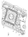
- Fig. 1
- is a perspective view of a vehicle cab inner roof panel with a HVAC drainage system embodying the invention,
- Fig. 2
- is an enlarged perspective view of a central portion of the inner roof panel shown in
Fig. 1 , - Fig. 3
- is an enlarged perspective view of another portion of the inner roof panel shown in
Fig. 1 , and - Fig. 4
- is a sectional view along lines 4-4 shown in
Fig. 3 . - Referring to
Fig. 1 , avehicle roof assembly 10 of a cab includes aninner roof panel 12 supported by a frame (not shown). Theinner roof panel 12 includes a central air inlet opening 26 surrounded by anHVAC compartment 28 over which is mounted anHVAC unit 30. Theinner roof panel 12 andHVAC unit 30 are preferably covered by a conventional upper or outer roof panel (not shown). Theinner roof panel 12 forms a collection recess 32 in the outer peripheral portion of theHVAC compartment 28. - An inner or first wall 40 (
Fig. 2 ) is formed by theinner roof panel 12 in thecollection recess 32. Thefirst wall 40 surrounds theHVAC compartment 28. A plurality of spaced-apartfirst gaps 42 is formed in thefirst wall 40. An intermediate orsecond wall 44 is formed by theinner roof panel 12 in the collection recess 32 and surrounds thefirst wall 40. Thesecond wall 44 has a plurality of spaced-apartsecond gaps 46 formed therein. Thefirst gaps 42 and thesecond gaps 46 are mis-aligned or offset with respect to each other so that fluid is prevented from flowing in a straight line through both afirst gap 42 and asecond gap 46. Athird wall 48 is formed by theinner roof panel 12 in the collection recess 32 and surrounding thesecond wall 44. Thethird wall 48 has a plurality of spaced-apartthird gaps 50 formed therein. Thethird gaps 50 and thesecond gaps 46 are mis-aligned or offset with respect to each other so that fluid is prevented from flowing in a straight line through both athird gap 50 and asecond gap 46. - A plurality of
drainage ports Fig. 1 ) is formed in theinner roof panel 12 spaced outwardly from thecollection recess 32. A plurality of grooves ordrainage channels inner roof panel 12. Eachdrainage channel drainage ports - A plurality of drainage tubes (not shown) is preferably coupled to the
drainage ports roof assembly 10. - As best seen in
Fig. 3 , each of thedrainage channels dams 70 which extend partially laterally cross the channel. Thesepartial dams 70 help reduce splashing of condensation in thedrainage channels - As best seen in
Figs. 3 and4 , the air inlet opening 26 is surrounded by an annular raisedhousing part 72. The floor of thedrainage channel 62 steps downward and slopes generally downward and away from the annular raisedhousing part 72, past thedams 70 to thedrainage port 54.Drainage channels respective drainage ports - This drainage system helps assure that condensation from the
HVAC unit 30, or any other liquid which is present in theHVAC compartment 28, is constrained to flow out of the roof throughdrainage channels inner roof panel 12. - As best seen in
Fig. 1 , theinner roof panel 12 hasholes 80 to 98 through which conditioned air is blown into the cab. Certain of these holes have awall 100 to 110 around them to prevent escaped water from running down one of these holes rather than into one of thedrainage ports - By having four paths for water to escape, the vehicle can run for unlimited time (as long as drains are clear) on a 25° slope without losing containment of the water. By having four drains, there is always a way for the water to escape without accumulating. Positive air pressure from the fan of the
HVAC unit 30 helps keep thedrainage channels - Because the
drainage channels inner roof panel 12 serves to contain and act as a drainage for the water without causing any damage. The water will simply run back to adrainage channel - Another advantage of the
drainage channels - While the present invention has been described in conjunction with a specific embodiment, it is understood that many alternatives, modifications and variations will be apparent to those skilled in the art in light of the foregoing description. Accordingly, this invention is intended to embrace all such alternatives, modifications and variations which fall within the spirit and scope of the appended claims.
Claims (7)
- A drainage system for an HVAC unit mounted on a vehicle inner roof panel (12) and over an air inlet opening (26) in the inner roof panel (12), the drainage system comprising a collection recess (32) formed by the inner roof panel (12) and surrounding the air inlet opening (26); a first wall (40) formed by the inner roof panel (12) in the collection recess (32) and surrounding the HVAC unit (30), the first wall (40) having a plurality of spaced-apart first gaps (42) formed therein; a second wall (44) formed by the inner roof panel (12) in the collection recess (32) and surrounding the first wall (40), the second wall (44) having a plurality of spaced-apart second gaps (46) formed therein, the first and second gaps (42, 46) being mis-aligned with respect to each other so that fluid is prevented from flowing in a straight line through both a first gap (42) and a second gap (46); a plurality of drainage ports (52, 54, 56, 58) formed in the inner roof panel (12); and a plurality of drainage channels (60, 62, 64, 66) formed in the inner roof panel (12), each drainage channel (60, 62, 64, 66) communicates between the collection recess (32) and a corresponding one of the drainage ports (52, 54, 56, 58).
- The drainage system according to claim 1, characterized by further comprising a third wall (48) formed by the inner roof panel (12) in the collection recess (32) and surrounding the second wall (44), the third wall (48) having a plurality of spaced-apart third gaps (50) formed therein, the third and second gaps (50, 46) being mis-aligned with respect to each other so that fluid is prevented from flowing in a straight line through both a third gap (50) and a second gap (46).
- The drainage system according to claim 1 or 2, characterized in that each drainage channel (60, 62, 64, 66) includes a plurality of dams (70) formed therein, each dam (70) extending part-way across said drainage channel (60, 62, 64, 66) so as to partially restrict fluid flow through the drainage channel (60, 62, 64, 66).
- The drainage system according to one of the preceding claims, characterized in that the inner roof panel (12) forms an annular raised housing part (72) surrounding the air inlet opening (26).
- The drainage system according to claim 4, characterized in that the collection recess (32) surrounds the annular raised housing part (72).
- The drainage system according to one of the preceding claims, characterized in that the collection recess (32) has a generally rectangular shape and each drainage channel (60, 62, 64, 66) communicates with a corner of the collection recess (32).
- The drainage system according to one of the preceding claims, characterized by further comprising a plurality of drainage tubes, each tube communicating with a corresponding one of the drainage ports (52, 54, 56, 58).
Applications Claiming Priority (1)
| Application Number | Priority Date | Filing Date | Title |
|---|---|---|---|
| US12/109,036 US8056355B2 (en) | 2008-04-24 | 2008-04-24 | HVAC drain system |
Publications (2)
| Publication Number | Publication Date |
|---|---|
| EP2112010A1 true EP2112010A1 (en) | 2009-10-28 |
| EP2112010B1 EP2112010B1 (en) | 2011-06-29 |
Family
ID=40852242
Family Applications (1)
| Application Number | Title | Priority Date | Filing Date |
|---|---|---|---|
| EP09157536A Active EP2112010B1 (en) | 2008-04-24 | 2009-04-07 | HVAC drain system |
Country Status (4)
| Country | Link |
|---|---|
| US (1) | US8056355B2 (en) |
| EP (1) | EP2112010B1 (en) |
| AT (1) | ATE514583T1 (en) |
| BR (1) | BRPI0900939B1 (en) |
Cited By (5)
| Publication number | Priority date | Publication date | Assignee | Title |
|---|---|---|---|---|
| EP2599652A1 (en) * | 2011-11-29 | 2013-06-05 | Iseki & Co., Ltd. | Working vehicle |
| WO2016030204A1 (en) * | 2014-08-28 | 2016-03-03 | Mahle International Gmbh | Air-conditioning system |
| EP3135515A1 (en) * | 2015-08-03 | 2017-03-01 | DongHwan Ind. Corp. | Drain pan structure of bus air conditioner for preventing overflow of condensate water |
| DE102020002416A1 (en) | 2020-04-22 | 2021-10-28 | Truma Gerätetechnik GmbH & Co. KG | Discharge device for discharging condensed water from an air conditioning system and a corresponding air conditioning system |
| US20230219399A1 (en) * | 2021-03-09 | 2023-07-13 | Ford Global Technologies, Llc | Heating, ventilation, and air conditioning assembly for vehicle roof |
Families Citing this family (4)
| Publication number | Priority date | Publication date | Assignee | Title |
|---|---|---|---|---|
| JP4467595B2 (en) * | 2007-03-28 | 2010-05-26 | 株式会社クボタ | Work vehicle canopy equipment |
| WO2013141844A1 (en) * | 2012-03-20 | 2013-09-26 | International Truck Intellectual Property Company, Llc | Roof assembly |
| US9434236B2 (en) | 2013-03-13 | 2016-09-06 | Deere & Company | Work vehicle HVAC control based on operator seat direction |
| US9550407B2 (en) | 2015-10-20 | 2017-01-24 | Caterpillar Inc. | HVAC integrated roof for operator cabs |
Citations (4)
| Publication number | Priority date | Publication date | Assignee | Title |
|---|---|---|---|---|
| FR2679986A1 (en) * | 1991-08-02 | 1993-02-05 | Thermofroid | Refrigeration appliance with universal mounting for cooling air with means for collection and removal of condensates |
| DE10015261A1 (en) * | 1999-04-08 | 2000-10-19 | Mitsubishi Heavy Ind Ltd | Overhead vehicle air conditioning unit; has cross flow fan with separate casing including stabiliser and heat exchanger arranged in two part casing mounted in ceiling of passenger compartment |
| EP1897711A2 (en) * | 2006-09-08 | 2008-03-12 | Deere & Company | Low profile HVAC system |
| WO2008099120A1 (en) * | 2007-01-31 | 2008-08-21 | Peugeot Citroën Automobiles SA | Sound proofing system for condensate discharge in the air conditioning system of an automotive vehicle |
Family Cites Families (19)
| Publication number | Priority date | Publication date | Assignee | Title |
|---|---|---|---|---|
| US2082998A (en) * | 1935-06-24 | 1937-06-08 | C L Horn | Heating-cooling device for automobiles |
| US2133354A (en) * | 1935-08-05 | 1938-10-18 | Hermann J Krackowizer | Condensation collector |
| DE1091084B (en) * | 1959-05-21 | 1960-10-20 | Gea Luftkuehler Ges M B H | Air-cooled condenser for the top product of a distillation or rectification column |
| US3848428A (en) * | 1973-05-21 | 1974-11-19 | Vapor Corp | Air conditioning system for a locomotive cab |
| US4098093A (en) * | 1976-12-06 | 1978-07-04 | Vapor Corporation | Unitary cab air cooling system for large off road vehicles |
| US4641502A (en) * | 1985-01-09 | 1987-02-10 | The Duo-Therm Corporation | Roof mount air conditioner |
| US4687604A (en) * | 1985-09-17 | 1987-08-18 | Goettl Adam D | Floor pan for evaporative coolers |
| US5209546A (en) * | 1986-07-25 | 1993-05-11 | Kinugawa Rubber Industrial Co., Ltd. | Structure for draining liquid for a vehicle and method for forming the structure |
| US5009464A (en) * | 1986-07-25 | 1991-04-23 | Kinugawa Rubber Industrial Co., Ltd. | Structure for draining liquid for a vehicle and method for forming the structure |
| US4926655A (en) * | 1989-05-01 | 1990-05-22 | Thermo King Corporation | Air conditioner unit suitable for mounting on the roof of a vehicle |
| JP3505313B2 (en) * | 1996-03-06 | 2004-03-08 | ベバスト ジャパン株式会社 | Drainage structure of sunroof equipment |
| US5791156A (en) * | 1997-01-06 | 1998-08-11 | Strautman; Thomas J. | Condensate drain pan for roof mounted vehicle air conditioning unit |
| US5938933A (en) * | 1997-08-28 | 1999-08-17 | Butler Manufacturing Company, Inc. | Condensate drain pan for HVAC units |
| US5878592A (en) * | 1998-05-20 | 1999-03-09 | Carrier Corporation | Evaporator housing |
| US6868689B1 (en) * | 2001-04-20 | 2005-03-22 | Buffalo Air Handling Company | Condensate drain pan |
| JP3793173B2 (en) * | 2002-11-25 | 2006-07-05 | エルジー電子株式会社 | Blower for cold air circulation in refrigerator |
| KR100457576B1 (en) * | 2002-11-28 | 2004-11-18 | 엘지전자 주식회사 | Dish washer |
| US6978909B2 (en) * | 2003-11-25 | 2005-12-27 | Advanced Distributor Products Llc | Condensate drain pan for air conditioning system |
| WO2005085716A1 (en) * | 2004-03-04 | 2005-09-15 | Lg Electronics Inc. | Indoor unit in air conditioner |
-
2008
- 2008-04-24 US US12/109,036 patent/US8056355B2/en not_active Expired - Fee Related
-
2009
- 2009-04-07 EP EP09157536A patent/EP2112010B1/en active Active
- 2009-04-07 AT AT09157536T patent/ATE514583T1/en not_active IP Right Cessation
- 2009-04-22 BR BRPI0900939-6A patent/BRPI0900939B1/en not_active IP Right Cessation
Patent Citations (5)
| Publication number | Priority date | Publication date | Assignee | Title |
|---|---|---|---|---|
| FR2679986A1 (en) * | 1991-08-02 | 1993-02-05 | Thermofroid | Refrigeration appliance with universal mounting for cooling air with means for collection and removal of condensates |
| DE10015261A1 (en) * | 1999-04-08 | 2000-10-19 | Mitsubishi Heavy Ind Ltd | Overhead vehicle air conditioning unit; has cross flow fan with separate casing including stabiliser and heat exchanger arranged in two part casing mounted in ceiling of passenger compartment |
| EP1897711A2 (en) * | 2006-09-08 | 2008-03-12 | Deere & Company | Low profile HVAC system |
| US20080060798A1 (en) | 2006-09-08 | 2008-03-13 | Deere & Company, A Delaware Corporation | Low profile HVAC system |
| WO2008099120A1 (en) * | 2007-01-31 | 2008-08-21 | Peugeot Citroën Automobiles SA | Sound proofing system for condensate discharge in the air conditioning system of an automotive vehicle |
Cited By (11)
| Publication number | Priority date | Publication date | Assignee | Title |
|---|---|---|---|---|
| EP2599652A1 (en) * | 2011-11-29 | 2013-06-05 | Iseki & Co., Ltd. | Working vehicle |
| CN103129345A (en) * | 2011-11-29 | 2013-06-05 | 井关农机株式会社 | Working vehicle |
| AU2012258463B2 (en) * | 2011-11-29 | 2015-01-22 | Iseki & Co., Ltd. | Working vehicle |
| US9316338B2 (en) | 2011-11-29 | 2016-04-19 | Iseki & Co., Ltd. | Front and rear condensate draining hoses for work vehicle |
| CN103129345B (en) * | 2011-11-29 | 2017-03-01 | 井关农机株式会社 | Tractor |
| WO2016030204A1 (en) * | 2014-08-28 | 2016-03-03 | Mahle International Gmbh | Air-conditioning system |
| EP3135515A1 (en) * | 2015-08-03 | 2017-03-01 | DongHwan Ind. Corp. | Drain pan structure of bus air conditioner for preventing overflow of condensate water |
| DE102020002416A1 (en) | 2020-04-22 | 2021-10-28 | Truma Gerätetechnik GmbH & Co. KG | Discharge device for discharging condensed water from an air conditioning system and a corresponding air conditioning system |
| WO2021213695A1 (en) | 2020-04-22 | 2021-10-28 | Truma Gerätetechnik GmbH & Co. KG | Air conditioning system having a discharge device for discharging condensed water |
| US20230219399A1 (en) * | 2021-03-09 | 2023-07-13 | Ford Global Technologies, Llc | Heating, ventilation, and air conditioning assembly for vehicle roof |
| US12054030B2 (en) * | 2021-03-09 | 2024-08-06 | Ford Global Technologies, Llc | Heating, ventilation, and air conditioning assembly for vehicle roof |
Also Published As
| Publication number | Publication date |
|---|---|
| US8056355B2 (en) | 2011-11-15 |
| BRPI0900939A2 (en) | 2010-04-06 |
| US20090266099A1 (en) | 2009-10-29 |
| ATE514583T1 (en) | 2011-07-15 |
| EP2112010B1 (en) | 2011-06-29 |
| BRPI0900939B1 (en) | 2020-11-03 |
Similar Documents
| Publication | Publication Date | Title |
|---|---|---|
| EP2112010B1 (en) | HVAC drain system | |
| KR101730171B1 (en) | Drain pan structure of bus air conditioner for preventing over flow of condensate water | |
| US9475362B2 (en) | Heating ventilating and air conditioning device for a vehicle | |
| US6901766B1 (en) | Coil drain pan apparatus | |
| US8056553B2 (en) | Condensate pan with condensate trap | |
| CN101468598B (en) | Vehicle front structure | |
| JP6079610B2 (en) | Drainage device and air conditioner provided with the same | |
| US6360911B1 (en) | Molded drain pan | |
| US20170051821A1 (en) | Transmission pan with integrated heat exchanger | |
| US20140374062A1 (en) | Outdoor unit of refrigeration apparatus | |
| JP2009092303A (en) | air conditioner | |
| JP2010281461A (en) | Air conditioner outdoor unit | |
| CN204665618U (en) | Air conditioning for automobiles Anti-air-leakage drainage mechanism | |
| US20230086543A1 (en) | Air conditioning system having a discharge device for discharging condensed water | |
| WO2007086641A3 (en) | Indoor unit of air conditioner | |
| CN220250138U (en) | Air conditioner | |
| JP3647532B2 (en) | Air conditioning unit | |
| JP2005098665A (en) | Evaporator core | |
| JP2011157002A (en) | Drain structure of air conditioner for vehicle | |
| US10723204B2 (en) | Vehicular air conditioning system | |
| JPH0359872B2 (en) | ||
| CN110422188B (en) | Embedded air conditioning unit | |
| JPH0568709U (en) | Automotive air conditioner | |
| CN114274730A (en) | Chassis and integrated vehicle-mounted air conditioner | |
| CN222378271U (en) | Outdoor unit and HVAC equipment |
Legal Events
| Date | Code | Title | Description |
|---|---|---|---|
| PUAI | Public reference made under article 153(3) epc to a published international application that has entered the european phase |
Free format text: ORIGINAL CODE: 0009012 |
|
| AK | Designated contracting states |
Kind code of ref document: A1 Designated state(s): AT BE BG CH CY CZ DE DK EE ES FI FR GB GR HR HU IE IS IT LI LT LU LV MC MK MT NL NO PL PT RO SE SI SK TR |
|
| 17P | Request for examination filed |
Effective date: 20100428 |
|
| GRAP | Despatch of communication of intention to grant a patent |
Free format text: ORIGINAL CODE: EPIDOSNIGR1 |
|
| GRAS | Grant fee paid |
Free format text: ORIGINAL CODE: EPIDOSNIGR3 |
|
| GRAA | (expected) grant |
Free format text: ORIGINAL CODE: 0009210 |
|
| AK | Designated contracting states |
Kind code of ref document: B1 Designated state(s): AT BE BG CH CY CZ DE DK EE ES FI FR GB GR HR HU IE IS IT LI LT LU LV MC MK MT NL NO PL PT RO SE SI SK TR |
|
| REG | Reference to a national code |
Ref country code: GB Ref legal event code: FG4D |
|
| REG | Reference to a national code |
Ref country code: CH Ref legal event code: EP |
|
| REG | Reference to a national code |
Ref country code: IE Ref legal event code: FG4D |
|
| REG | Reference to a national code |
Ref country code: DE Ref legal event code: R096 Ref document number: 602009001659 Country of ref document: DE Effective date: 20110908 |
|
| REG | Reference to a national code |
Ref country code: NL Ref legal event code: VDEP Effective date: 20110629 |
|
| PG25 | Lapsed in a contracting state [announced via postgrant information from national office to epo] |
Ref country code: LT Free format text: LAPSE BECAUSE OF FAILURE TO SUBMIT A TRANSLATION OF THE DESCRIPTION OR TO PAY THE FEE WITHIN THE PRESCRIBED TIME-LIMIT Effective date: 20110629 Ref country code: SE Free format text: LAPSE BECAUSE OF FAILURE TO SUBMIT A TRANSLATION OF THE DESCRIPTION OR TO PAY THE FEE WITHIN THE PRESCRIBED TIME-LIMIT Effective date: 20110629 Ref country code: HR Free format text: LAPSE BECAUSE OF FAILURE TO SUBMIT A TRANSLATION OF THE DESCRIPTION OR TO PAY THE FEE WITHIN THE PRESCRIBED TIME-LIMIT Effective date: 20110629 Ref country code: NO Free format text: LAPSE BECAUSE OF FAILURE TO SUBMIT A TRANSLATION OF THE DESCRIPTION OR TO PAY THE FEE WITHIN THE PRESCRIBED TIME-LIMIT Effective date: 20110929 |
|
| PG25 | Lapsed in a contracting state [announced via postgrant information from national office to epo] |
Ref country code: AT Free format text: LAPSE BECAUSE OF FAILURE TO SUBMIT A TRANSLATION OF THE DESCRIPTION OR TO PAY THE FEE WITHIN THE PRESCRIBED TIME-LIMIT Effective date: 20110629 Ref country code: SI Free format text: LAPSE BECAUSE OF FAILURE TO SUBMIT A TRANSLATION OF THE DESCRIPTION OR TO PAY THE FEE WITHIN THE PRESCRIBED TIME-LIMIT Effective date: 20110629 Ref country code: FI Free format text: LAPSE BECAUSE OF FAILURE TO SUBMIT A TRANSLATION OF THE DESCRIPTION OR TO PAY THE FEE WITHIN THE PRESCRIBED TIME-LIMIT Effective date: 20110629 Ref country code: LV Free format text: LAPSE BECAUSE OF FAILURE TO SUBMIT A TRANSLATION OF THE DESCRIPTION OR TO PAY THE FEE WITHIN THE PRESCRIBED TIME-LIMIT Effective date: 20110629 Ref country code: GR Free format text: LAPSE BECAUSE OF FAILURE TO SUBMIT A TRANSLATION OF THE DESCRIPTION OR TO PAY THE FEE WITHIN THE PRESCRIBED TIME-LIMIT Effective date: 20110930 |
|
| PG25 | Lapsed in a contracting state [announced via postgrant information from national office to epo] |
Ref country code: BE Free format text: LAPSE BECAUSE OF FAILURE TO SUBMIT A TRANSLATION OF THE DESCRIPTION OR TO PAY THE FEE WITHIN THE PRESCRIBED TIME-LIMIT Effective date: 20110629 |
|
| PG25 | Lapsed in a contracting state [announced via postgrant information from national office to epo] |
Ref country code: PT Free format text: LAPSE BECAUSE OF FAILURE TO SUBMIT A TRANSLATION OF THE DESCRIPTION OR TO PAY THE FEE WITHIN THE PRESCRIBED TIME-LIMIT Effective date: 20111031 Ref country code: EE Free format text: LAPSE BECAUSE OF FAILURE TO SUBMIT A TRANSLATION OF THE DESCRIPTION OR TO PAY THE FEE WITHIN THE PRESCRIBED TIME-LIMIT Effective date: 20110629 Ref country code: CZ Free format text: LAPSE BECAUSE OF FAILURE TO SUBMIT A TRANSLATION OF THE DESCRIPTION OR TO PAY THE FEE WITHIN THE PRESCRIBED TIME-LIMIT Effective date: 20110629 Ref country code: IS Free format text: LAPSE BECAUSE OF FAILURE TO SUBMIT A TRANSLATION OF THE DESCRIPTION OR TO PAY THE FEE WITHIN THE PRESCRIBED TIME-LIMIT Effective date: 20111029 Ref country code: NL Free format text: LAPSE BECAUSE OF FAILURE TO SUBMIT A TRANSLATION OF THE DESCRIPTION OR TO PAY THE FEE WITHIN THE PRESCRIBED TIME-LIMIT Effective date: 20110629 |
|
| PG25 | Lapsed in a contracting state [announced via postgrant information from national office to epo] |
Ref country code: SK Free format text: LAPSE BECAUSE OF FAILURE TO SUBMIT A TRANSLATION OF THE DESCRIPTION OR TO PAY THE FEE WITHIN THE PRESCRIBED TIME-LIMIT Effective date: 20110629 Ref country code: CY Free format text: LAPSE BECAUSE OF FAILURE TO SUBMIT A TRANSLATION OF THE DESCRIPTION OR TO PAY THE FEE WITHIN THE PRESCRIBED TIME-LIMIT Effective date: 20110629 Ref country code: PL Free format text: LAPSE BECAUSE OF FAILURE TO SUBMIT A TRANSLATION OF THE DESCRIPTION OR TO PAY THE FEE WITHIN THE PRESCRIBED TIME-LIMIT Effective date: 20110629 |
|
| PLBE | No opposition filed within time limit |
Free format text: ORIGINAL CODE: 0009261 |
|
| STAA | Information on the status of an ep patent application or granted ep patent |
Free format text: STATUS: NO OPPOSITION FILED WITHIN TIME LIMIT |
|
| PG25 | Lapsed in a contracting state [announced via postgrant information from national office to epo] |
Ref country code: IT Free format text: LAPSE BECAUSE OF FAILURE TO SUBMIT A TRANSLATION OF THE DESCRIPTION OR TO PAY THE FEE WITHIN THE PRESCRIBED TIME-LIMIT Effective date: 20110629 |
|
| 26N | No opposition filed |
Effective date: 20120330 |
|
| PG25 | Lapsed in a contracting state [announced via postgrant information from national office to epo] |
Ref country code: DK Free format text: LAPSE BECAUSE OF FAILURE TO SUBMIT A TRANSLATION OF THE DESCRIPTION OR TO PAY THE FEE WITHIN THE PRESCRIBED TIME-LIMIT Effective date: 20110629 |
|
| REG | Reference to a national code |
Ref country code: DE Ref legal event code: R097 Ref document number: 602009001659 Country of ref document: DE Effective date: 20120330 |
|
| PG25 | Lapsed in a contracting state [announced via postgrant information from national office to epo] |
Ref country code: MC Free format text: LAPSE BECAUSE OF NON-PAYMENT OF DUE FEES Effective date: 20120430 |
|
| REG | Reference to a national code |
Ref country code: IE Ref legal event code: MM4A |
|
| PG25 | Lapsed in a contracting state [announced via postgrant information from national office to epo] |
Ref country code: IE Free format text: LAPSE BECAUSE OF NON-PAYMENT OF DUE FEES Effective date: 20120407 |
|
| PG25 | Lapsed in a contracting state [announced via postgrant information from national office to epo] |
Ref country code: MK Free format text: LAPSE BECAUSE OF FAILURE TO SUBMIT A TRANSLATION OF THE DESCRIPTION OR TO PAY THE FEE WITHIN THE PRESCRIBED TIME-LIMIT Effective date: 20110629 |
|
| PG25 | Lapsed in a contracting state [announced via postgrant information from national office to epo] |
Ref country code: ES Free format text: LAPSE BECAUSE OF FAILURE TO SUBMIT A TRANSLATION OF THE DESCRIPTION OR TO PAY THE FEE WITHIN THE PRESCRIBED TIME-LIMIT Effective date: 20111010 |
|
| PG25 | Lapsed in a contracting state [announced via postgrant information from national office to epo] |
Ref country code: BG Free format text: LAPSE BECAUSE OF FAILURE TO SUBMIT A TRANSLATION OF THE DESCRIPTION OR TO PAY THE FEE WITHIN THE PRESCRIBED TIME-LIMIT Effective date: 20110929 |
|
| PG25 | Lapsed in a contracting state [announced via postgrant information from national office to epo] |
Ref country code: MT Free format text: LAPSE BECAUSE OF FAILURE TO SUBMIT A TRANSLATION OF THE DESCRIPTION OR TO PAY THE FEE WITHIN THE PRESCRIBED TIME-LIMIT Effective date: 20110629 |
|
| REG | Reference to a national code |
Ref country code: CH Ref legal event code: PL |
|
| GBPC | Gb: european patent ceased through non-payment of renewal fee |
Effective date: 20130407 |
|
| PG25 | Lapsed in a contracting state [announced via postgrant information from national office to epo] |
Ref country code: CH Free format text: LAPSE BECAUSE OF NON-PAYMENT OF DUE FEES Effective date: 20130430 Ref country code: GB Free format text: LAPSE BECAUSE OF NON-PAYMENT OF DUE FEES Effective date: 20130407 Ref country code: LI Free format text: LAPSE BECAUSE OF NON-PAYMENT OF DUE FEES Effective date: 20130430 |
|
| PG25 | Lapsed in a contracting state [announced via postgrant information from national office to epo] |
Ref country code: TR Free format text: LAPSE BECAUSE OF FAILURE TO SUBMIT A TRANSLATION OF THE DESCRIPTION OR TO PAY THE FEE WITHIN THE PRESCRIBED TIME-LIMIT Effective date: 20110629 |
|
| PG25 | Lapsed in a contracting state [announced via postgrant information from national office to epo] |
Ref country code: LU Free format text: LAPSE BECAUSE OF NON-PAYMENT OF DUE FEES Effective date: 20120407 |
|
| PG25 | Lapsed in a contracting state [announced via postgrant information from national office to epo] |
Ref country code: HU Free format text: LAPSE BECAUSE OF FAILURE TO SUBMIT A TRANSLATION OF THE DESCRIPTION OR TO PAY THE FEE WITHIN THE PRESCRIBED TIME-LIMIT Effective date: 20090407 |
|
| REG | Reference to a national code |
Ref country code: FR Ref legal event code: PLFP Year of fee payment: 8 |
|
| PGFP | Annual fee paid to national office [announced via postgrant information from national office to epo] |
Ref country code: FR Payment date: 20160425 Year of fee payment: 8 |
|
| REG | Reference to a national code |
Ref country code: FR Ref legal event code: ST Effective date: 20171229 |
|
| PG25 | Lapsed in a contracting state [announced via postgrant information from national office to epo] |
Ref country code: FR Free format text: LAPSE BECAUSE OF NON-PAYMENT OF DUE FEES Effective date: 20170502 |
|
| PGFP | Annual fee paid to national office [announced via postgrant information from national office to epo] |
Ref country code: DE Payment date: 20230321 Year of fee payment: 15 |
|
| REG | Reference to a national code |
Ref country code: DE Ref legal event code: R119 Ref document number: 602009001659 Country of ref document: DE |
|
| PG25 | Lapsed in a contracting state [announced via postgrant information from national office to epo] |
Ref country code: DE Free format text: LAPSE BECAUSE OF NON-PAYMENT OF DUE FEES Effective date: 20241105 |
|
| PG25 | Lapsed in a contracting state [announced via postgrant information from national office to epo] |
Ref country code: DE Free format text: LAPSE BECAUSE OF NON-PAYMENT OF DUE FEES Effective date: 20241105 |