EP2111090A2 - Cable management apparatus - Google Patents
Cable management apparatus Download PDFInfo
- Publication number
- EP2111090A2 EP2111090A2 EP08253921A EP08253921A EP2111090A2 EP 2111090 A2 EP2111090 A2 EP 2111090A2 EP 08253921 A EP08253921 A EP 08253921A EP 08253921 A EP08253921 A EP 08253921A EP 2111090 A2 EP2111090 A2 EP 2111090A2
- Authority
- EP
- European Patent Office
- Prior art keywords
- support
- management apparatus
- cable management
- rail
- cable
- Prior art date
- Legal status (The legal status is an assumption and is not a legal conclusion. Google has not performed a legal analysis and makes no representation as to the accuracy of the status listed.)
- Granted
Links
Images



Classifications
-
- H—ELECTRICITY
- H05—ELECTRIC TECHNIQUES NOT OTHERWISE PROVIDED FOR
- H05K—PRINTED CIRCUITS; CASINGS OR CONSTRUCTIONAL DETAILS OF ELECTRIC APPARATUS; MANUFACTURE OF ASSEMBLAGES OF ELECTRICAL COMPONENTS
- H05K7/00—Constructional details common to different types of electric apparatus
- H05K7/14—Mounting supporting structure in casing or on frame or rack
- H05K7/1485—Servers; Data center rooms, e.g. 19-inch computer racks
- H05K7/1488—Cabinets therefor, e.g. chassis or racks or mechanical interfaces between blades and support structures
- H05K7/1491—Cabinets therefor, e.g. chassis or racks or mechanical interfaces between blades and support structures having cable management arrangements
Definitions
- the present invention relates to an accessory of a server cabinet, and more particularly to a cable management apparatus attached to a server cabinet to manage the cables connected to a server.
- a server is installed in a cabinet via a pair of rail assemblies.
- a cable management apparatus is attached to the cabinet behind the server to manage the cables of the server to ensure that the cables are well ordered.
- the cable management apparatus generally includes a first supporting arm pivotably connected with a second supporting arm.
- the first and second supporting arms are attached to a rail assembly, and can rotate relative to each other when the server moves with the rail assemblies. But, when the server stays stationary, the first and second supporting arms can not rotate any more and block the access to the rear part of the sever.
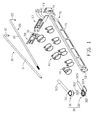
- FIG. 1 is an exploded, isometric view of a cable management apparatus in accordance with a first embodiment of the present invention
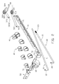
- FIG. 2 is similar to FIG. 1 , but an inverted view
- FIG. 3 is an assembled view of FIG. 1 ;
- FIGS. 4 and 5 are assembled views of the cable management apparatus of FIG. 1 , two rail assemblies, and a server, showing two using states respectively;
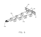
- FIG. 6 is an assembled, isometric view of a cable management apparatus in accordance with a second embodiment of the present invention.
- FIG. 7 is an assembled, isometric view of the cable management apparatus of FIG. 6 , two rail assemblies, and a server, showing a using state.
- a cable management apparatus in accordance with a first embodiment of the present invention is attached between a first rail assembly 80 and a second rail assembly 90, for managing cables 110 extending from a rear end of a server 100.
- the cable management apparatus includes a first supporting arm 10, a second supporting arm 20, a connecting member 30, a plurality of cable retainers 40, a first locking member 50, a second locking member 60, and a supporting member 70.
- a rear end of the first rail assembly 80 defines a fixing hole 81 (see FIG. 5 ).
- the first supporting arm 10 is approximately L-shaped, and includes a pole-shaped supporting portion 11, and a pivot portion 12 vertically extending from a first end of the supporting portion 11.
- the second supporting arm 20 is approximately L-shaped, and includes a pole-shaped supporting portion 21, a pivot portion 22 vertically extending from a first end of the supporting portion 21, and a threaded portion 23 defined at a second end of the supporting portion 21.
- the connecting member 30 includes a first connecting part 31 and a second connecting part 32.
- the first connecting part 31 includes a tube 313, a discoid-shaped hook portion 311 extending from an end of the tube 313, and a plurality of circularly distributed hooks 312 vertically extending from a circumference of a bottom of the hook portion 311.
- the tube 313 defines an axial hole 3132 therein.
- the second connecting part 32 includes a fixing pole 323, a discoid-shaped receiving portion 321 extending from an end of the fixing pole 323, and a blocking portion 324 radially extending outward from the receiving portion 321.
- the receiving portion 321 defines a stepped hole in a middle thereof.
- the other end of the fixing pole 323 axially defines a threaded hole 3232, corresponding to the threaded portion 23 of the second supporting arm 20.
- Each cable retainer 40 may be formed by a wire bent into a U-shape. Distal ends 41 thereof are coiled and in axial alignment to receive a corresponding pole-shape supporting portion 11, 21 therethrough. The middle portion is bent toward the coiled ends 41 to form a hook like structure.
- the first locking member 50 is approximately L-shaped, and includes an attaching portion and an extending portion vertically bent from one end of the attaching portion.
- a pivot part 51 is formed at a distal end of the extending portion.
- the second locking member 60 includes an attaching portion, an extending portion vertically bent from one end of the attaching portion, and an elastic part 62 vertically bent from a distal end of the extending portion.
- a pivot part 61 is formed at an outer surface of the extending portion.
- Two cutouts 621 are respectively defined at opposite sides of the free end of the elastic part 62.
- the supporting member 70 includes a supporting portion 71, a protrusion 72 extending outward from one end of the supporting portion 71, and a fixing portion 73 vertically bent from the other end of the supporting portion 71.
- the supporting portion 71 defines a fixing hole 74 adjacent the fixing portion 73.
- the fixing hole 74 includes a greater section and a smaller section communicating with the greater section.
- the hooks 312 of the first connecting part 31 of the connecting member 30 is extended into the stepped hole 322 of the second connecting part 32 from the smaller hole of the stepped hole 322, and engaged with the step of the stepped hole 322.
- the first connecting part 31 is rotationally mounted to the second connecting part 32.
- the cable retainers 40 are positioned on the tube 313 of the first connecting part 31, the supporting portion 11 of the first supporting arm 10, or the supporting portion 21 of the second supporting arm 20, via their coiled ends 41.
- the cable 110 can be retained by the cable retainers 40.
- the supporting portion 11 of the first supporting arm 10 is slidably received in the axial hole 3132 of the tube 313 of the first connecting part 31, and the threaded portion 23 of the second supporting arm 20 is screwed into the threaded hole 3232 of the fixing pole 323 of the second connecting part 32 of the connecting member 30.
- the pivot portion 12 of the first supporting arm 10 and the pivot portion 22 of the second supporting arm 20 are respectively rotationally received in the pivot part 51 of the first locking member 50 and the pivot part 61 of the second locking member 60.
- the attaching portions of the first locking member 50 and the second locking member 60 are respectively fixed to rear ends of an inner rail and an outer rail of the second rail assembly 90.
- the protrusion 72 of the supporting member 70 is engaged in the fixing hole 81 of the first rail assembly 80.
- the fixing portion 73 of the supporting member 70 is inserted into an inner side of the outer rail of the second rail assembly 90.
- the elastic part 62 of the second locking member 60 is elastically deformed and passes through the greater section of the fixing hole 74 of the supporting member 70.
- the elastic part 62 of the second locking member 60 restores and moves into the smaller section of the fixing hole 74, and the cutouts 621 of the elastic part 62 are engaged with opposite edges of the smaller section of the fixing hole 74.
- a top of the supporting portion 71 of the supporting member 70 supports the blocking portion 324 of the second connecting part 32 of the connecting member 30, to prevent the cable management apparatus from damage because of supporting heavy cables 110 for a long time.
- the cables 110 When the server is moved forwards on the rail assemblies 80, 90, the cables 110 are supported by the cable retainers 40 and the first supporting arm 10 rotates relative to the second supporting arm 20.
- the cables 110 also supplies a force to prevent the supporting portion 11 of the first supporting arm 10 from sliding in the tube 313 of the first connecting part 31 of the connecting member 30.
- the blocking portion 324 is moved off of the supporting member 70.
- the cables 110 are maintained in a well ordered manner such that when the server is pushed back, the cables 110 do not get in the way of the server progress.
- the elastic part 62 of the second locking member 60 is moved into the greater section of the fixing hole 74 of the supporting member 70 against its elasticity.
- the fixing portion 73 of the supporting member 70 is drawn out of the outer rail of the second rail assembly 90, and the protrusion 72 of the supporting member 70 is disengaged from the fixing hole 81 of the first rail assembly 80 to detach the supporting member 70.
- the pivot portion 12 of the first supporting arm 10 and the pivot portion 22 of the second supporting arm 20 are respectively pivoted in the pivot part 51 of the first locking member 50 and the pivot part 61 of the second locking member 60.
- the first supporting arm 10 and the second supporting arm 20 can move toward the second rail assembly 90.
- the supporting portion 11 of the first supporting arm 10 slides in the tube 313 of the first connecting part 31 of the connecting member 30, until the first supporting arm 10 and the second supporting arm 20 are juxtaposed, and located beside the second rail assembly 90 to leave a space for the technicians to maintain the components of the server 100.
- the relative lengths of two sides the respective triangle can be altered allowing easy service of the servers.
- a cable management apparatus in accordance with a second embodiment of the present invention is similar to that of the first embodiment.
- the cable management apparatus of this embodiment includes a first supporting arm 10a, a second supporting arm 20a, and a connecting member 30a.
- the connecting member 30a is a helical spring, and both ends of the helical spring are fixed to the corresponding ends of the first supporting arm 10a and the second supporting arm 20a.
- the pivot portions of the first supporting arm 10a and the second supporting arm 20a are respectively pivoted in the pivot part 51 of the first locking member 50 and the pivot part 61 of the second locking member 60, until the first and the second supporting arms 10a, 20a are juxtaposed, and located beside the second rail assembly 90, to leave a space for the technicians to maintain the components of the server 100.
- the relative lengths of two sides the respective triangle can be altered allowing easy service of the servers.
Landscapes
- Engineering & Computer Science (AREA)
- Computer Hardware Design (AREA)
- General Engineering & Computer Science (AREA)
- Microelectronics & Electronic Packaging (AREA)
- Installation Of Indoor Wiring (AREA)
- Insertion, Bundling And Securing Of Wires For Electric Apparatuses (AREA)
- Clamps And Clips (AREA)
- Laying Of Electric Cables Or Lines Outside (AREA)
- Electric Cable Arrangement Between Relatively Moving Parts (AREA)
Abstract
Description
- The present invention relates to an accessory of a server cabinet, and more particularly to a cable management apparatus attached to a server cabinet to manage the cables connected to a server.
- Generally, a server is installed in a cabinet via a pair of rail assemblies. A cable management apparatus is attached to the cabinet behind the server to manage the cables of the server to ensure that the cables are well ordered. The cable management apparatus generally includes a first supporting arm pivotably connected with a second supporting arm. The first and second supporting arms are attached to a rail assembly, and can rotate relative to each other when the server moves with the rail assemblies. But, when the server stays stationary, the first and second supporting arms can not rotate any more and block the access to the rear part of the sever.
- Because of the existence of the above cable management apparatus, maintenance of the components behind the server such as power supply modules becomes inconvenient. The cable management apparatus must be detached from the cabinet to provide access for the maintenance.
- What is desired, therefore, is a cable management apparatus that facilitates the maintenance of servers.
-
FIG. 1 is an exploded, isometric view of a cable management apparatus in accordance with a first embodiment of the present invention; -
FIG. 2 is similar toFIG. 1 , but an inverted view; -
FIG. 3 is an assembled view ofFIG. 1 ; -
FIGS. 4 and5 are assembled views of the cable management apparatus ofFIG. 1 , two rail assemblies, and a server, showing two using states respectively; -
FIG. 6 is an assembled, isometric view of a cable management apparatus in accordance with a second embodiment of the present invention; and -
FIG. 7 is an assembled, isometric view of the cable management apparatus ofFIG. 6 , two rail assemblies, and a server, showing a using state. - Referring to
FIGS. 1 ,2 and4 , a cable management apparatus in accordance with a first embodiment of the present invention is attached between afirst rail assembly 80 and asecond rail assembly 90, for managingcables 110 extending from a rear end of aserver 100. The cable management apparatus includes a first supportingarm 10, a second supportingarm 20, a connectingmember 30, a plurality ofcable retainers 40, afirst locking member 50, asecond locking member 60, and a supportingmember 70. - A rear end of the
first rail assembly 80 defines a fixing hole 81 (seeFIG. 5 ). - The first supporting
arm 10 is approximately L-shaped, and includes a pole-shaped supportingportion 11, and apivot portion 12 vertically extending from a first end of the supportingportion 11. - The second supporting
arm 20 is approximately L-shaped, and includes a pole-shaped supportingportion 21, apivot portion 22 vertically extending from a first end of the supportingportion 21, and a threadedportion 23 defined at a second end of the supportingportion 21. - The connecting
member 30 includes a first connectingpart 31 and a second connectingpart 32. The first connectingpart 31 includes atube 313, a discoid-shaped hook portion 311 extending from an end of thetube 313, and a plurality of circularlydistributed hooks 312 vertically extending from a circumference of a bottom of thehook portion 311. Thetube 313 defines anaxial hole 3132 therein. The second connectingpart 32 includes afixing pole 323, a discoid-shapedreceiving portion 321 extending from an end of thefixing pole 323, and a blockingportion 324 radially extending outward from thereceiving portion 321. Thereceiving portion 321 defines a stepped hole in a middle thereof. The other end of thefixing pole 323 axially defines a threadedhole 3232, corresponding to the threadedportion 23 of the second supportingarm 20. - Each
cable retainer 40 may be formed by a wire bent into a U-shape.Distal ends 41 thereof are coiled and in axial alignment to receive a corresponding pole-shape supporting portion coiled ends 41 to form a hook like structure. - The
first locking member 50 is approximately L-shaped, and includes an attaching portion and an extending portion vertically bent from one end of the attaching portion. Apivot part 51 is formed at a distal end of the extending portion. - The
second locking member 60 includes an attaching portion, an extending portion vertically bent from one end of the attaching portion, and anelastic part 62 vertically bent from a distal end of the extending portion. Apivot part 61 is formed at an outer surface of the extending portion. Twocutouts 621 are respectively defined at opposite sides of the free end of theelastic part 62. - The supporting
member 70 includes a supportingportion 71, aprotrusion 72 extending outward from one end of the supportingportion 71, and afixing portion 73 vertically bent from the other end of the supportingportion 71. The supportingportion 71 defines afixing hole 74 adjacent thefixing portion 73. Thefixing hole 74 includes a greater section and a smaller section communicating with the greater section. - Referring also to
FIGS. 3 to 5 , in assembly, thehooks 312 of the first connectingpart 31 of the connectingmember 30 is extended into thestepped hole 322 of the second connectingpart 32 from the smaller hole of thestepped hole 322, and engaged with the step of thestepped hole 322. The first connectingpart 31 is rotationally mounted to the second connectingpart 32. Thecable retainers 40 are positioned on thetube 313 of the first connectingpart 31, the supportingportion 11 of the first supportingarm 10, or the supportingportion 21 of the second supportingarm 20, via theircoiled ends 41. Thecable 110 can be retained by thecable retainers 40. The supportingportion 11 of the first supportingarm 10 is slidably received in theaxial hole 3132 of thetube 313 of the first connectingpart 31, and the threadedportion 23 of the second supportingarm 20 is screwed into the threadedhole 3232 of thefixing pole 323 of the second connectingpart 32 of the connectingmember 30. Thepivot portion 12 of the first supportingarm 10 and thepivot portion 22 of the second supportingarm 20 are respectively rotationally received in thepivot part 51 of thefirst locking member 50 and thepivot part 61 of thesecond locking member 60. The attaching portions of thefirst locking member 50 and thesecond locking member 60 are respectively fixed to rear ends of an inner rail and an outer rail of thesecond rail assembly 90. Theprotrusion 72 of the supportingmember 70 is engaged in thefixing hole 81 of thefirst rail assembly 80. Thefixing portion 73 of the supportingmember 70 is inserted into an inner side of the outer rail of thesecond rail assembly 90. Theelastic part 62 of thesecond locking member 60 is elastically deformed and passes through the greater section of thefixing hole 74 of the supportingmember 70. Theelastic part 62 of thesecond locking member 60 restores and moves into the smaller section of thefixing hole 74, and thecutouts 621 of theelastic part 62 are engaged with opposite edges of the smaller section of thefixing hole 74. - When the
server 100 is completely accommodated in the cabinet, a top of the supportingportion 71 of the supportingmember 70 supports the blockingportion 324 of the second connectingpart 32 of the connectingmember 30, to prevent the cable management apparatus from damage because of supportingheavy cables 110 for a long time. - When the server is moved forwards on the
rail assemblies cables 110 are supported by thecable retainers 40 and the first supportingarm 10 rotates relative to the second supportingarm 20. Thecables 110 also supplies a force to prevent the supportingportion 11 of the first supportingarm 10 from sliding in thetube 313 of the first connectingpart 31 of the connectingmember 30. The blockingportion 324 is moved off of the supportingmember 70. Thecables 110 are maintained in a well ordered manner such that when the server is pushed back, thecables 110 do not get in the way of the server progress. - When components of the
server 100 need to be maintenanced, theelastic part 62 of thesecond locking member 60 is moved into the greater section of thefixing hole 74 of the supportingmember 70 against its elasticity. Thefixing portion 73 of the supportingmember 70 is drawn out of the outer rail of thesecond rail assembly 90, and theprotrusion 72 of the supportingmember 70 is disengaged from thefixing hole 81 of thefirst rail assembly 80 to detach the supportingmember 70. Thepivot portion 12 of the first supportingarm 10 and thepivot portion 22 of the second supportingarm 20 are respectively pivoted in thepivot part 51 of thefirst locking member 50 and thepivot part 61 of thesecond locking member 60. The first supportingarm 10 and the second supportingarm 20 can move toward thesecond rail assembly 90. The supportingportion 11 of the first supportingarm 10 slides in thetube 313 of the first connectingpart 31 of the connectingmember 30, until the first supportingarm 10 and the second supportingarm 20 are juxtaposed, and located beside thesecond rail assembly 90 to leave a space for the technicians to maintain the components of theserver 100. Thus, the relative lengths of two sides the respective triangle can be altered allowing easy service of the servers. - Referring also to
FIGS. 6 and7 , a cable management apparatus in accordance with a second embodiment of the present invention is similar to that of the first embodiment. The cable management apparatus of this embodiment includes a first supportingarm 10a, a second supportingarm 20a, and a connectingmember 30a. The connectingmember 30a is a helical spring, and both ends of the helical spring are fixed to the corresponding ends of the first supportingarm 10a and the second supportingarm 20a. When components of theserver 100 need to be maintenanced. In virtue of the flexibility of the connectingmember 30a, the pivot portions of the first supportingarm 10a and the second supportingarm 20a are respectively pivoted in thepivot part 51 of the first lockingmember 50 and thepivot part 61 of thesecond locking member 60, until the first and the second supportingarms second rail assembly 90, to leave a space for the technicians to maintain the components of theserver 100. Thus, the relative lengths of two sides the respective triangle can be altered allowing easy service of the servers. - The foregoing description of the exemplary embodiments of the invention has been presented only for the purposes of illustration and description and is not intended to be exhaustive or to limit the invention to the precise forms disclosed. Many modifications and variations are possible in light of the above teaching. The embodiments were chosen and described in order to explain the principles of the invention and their practical application so as to enable others skilled in the art to utilize the invention and various embodiments and with various modifications as are suited to the particular use contemplated. Alternative embodiments will become apparent to those skilled in the art to which the present invention pertains without departing from its spirit and scope. Accordingly, the scope of the present invention is defined by the appended claims rather than the foregoing description and the exemplary embodiments described therein.
Claims (18)
- A cable management apparatus, the cable management apparatus comprising:a rail assembly comprising of an outer rail and an inner rail slidably attached to the outer rail;a first support comprising of a first support section and a first rotation section, wherein the first rotation section is capable of rotational attached to the inner rail;a second support comprising of a second support section and a second rotation section, wherein the second rotation section is capable of rotational attached to the outer rail; anda connecting member comprising of a first connecting part and a second connecting part, wherein the first connecting part connects with the first support section and the second connecting part connects with the second support section, and the first connecting part and the second connecting part are capable of rotational relative movement;wherein the first support is capable of changing position relative to the second support while the inner rail and the outer rail stay relatively static.
- The cable management apparatus as claimed in claim 1, wherein the inner rail comprises a first locking member and the outer rail comprises a second locking member, the first rotation section is pivotally coupled to the first locking member and the second rotation section is pivotally coupled to the second locking member.
- The cable management apparatus as claimed in claim 1, wherein the first support section is slidably received in the first receiving section and the second support section is fixedly received in the second receiving section.
- The cable management apparatus as claimed in claim 3, wherein the first connecting part comprises a tube slidably receiving the first support section of the first support.
- The cable management apparatus as claimed in claim 3, wherein the second support section defines a threaded portion and the second connecting part defines corresponding threaded portion; the treaded portion of the second support section in engaged with the treaded portion of the second connecting part.
- The cable management apparatus as claimed in claim 1, wherein the connecting member is a spring, with opposite ends thereof fixed to the first and the second support section.
- The cable management apparatus as claimed in claim 6, wherein the connecting member is a helical spring.
- The cable management apparatus as claimed in claim 1, further comprising a plurality of cable retainers, wherein at lease one cable retainer is located on each of the first and second supports.
- The cable management apparatus as claimed in claim 11, wherein each cable retainer is formed by a wire bent into a U-shape; the ends thereof are coiled and in axial alignment; the middle portion is bent toward the coiled ends to form a hook like structure.
- A cable management apparatus, the cable management apparatus comprising:a first rail assembly and a second rail assembly that are opposite and parallel to each other;a cable support member;a blocking portion extending from the cable support member; anda supporting member removably attached to the first and second rail assemblies;wherein the blocking portion is supported by the supporting member and is capable of disengaging from the supporting member.
- The cable management apparatus as claimed in claim 10, wherein the supporting member comprises:a supporting portion that engages the blocking portion;a protrusion extending from a supporting member first end that is engaged with a rear end of the second rail assembly;a fixing portion extending from a supporting member second end that is engaged with a rear end of the first rail assembly; anda fixing hole defined in the supporting portion adjacent the fixing portion, the fixing hole engages with an elastic part of the first rail assembly.
- The cable management apparatus as claimed in claim 11, wherein the first rail assembly comprises an outer rail and an inner rail slidably attached to the outer rail.
- The cable management apparatus as claimed in claim 12, wherein the cable support member comprises a first support rotationally attached to the inner rail, a second support rotationally attached to the outer rail, and a connecting member connecting the first and second supports.
- The cable management apparatus as claimed in claim 13, wherein the blocking portion is extended from the connecting member.
- The cable management apparatus as claimed in claim 13, wherein the inner rail comprises a first locking member and the outer rail comprises a second locking member, the first support is attached to the first locking member and the second support is attached to the second locking member.
- The cable management apparatus as claimed in claim 15, wherein the elastic part is attached to the second locking member.
- The cable management apparatus as claimed in claim 11, wherein the elastic part defines two cutouts in opposite sides of the elastic part free end respectively, to engage with sides of the fixing hole of the supporting portion.
- A cable management apparatus, the cable management apparatus comprising:a first rail assembly and a second rail assembly that are opposite and parallel to each other, the first rail assembly comprising an outer rail and an inner rail slidably attached to the outer rail;a cable support member, the cable support member comprising:a first support comprising of a first support section and a first rotation section, wherein the first rotation section is rotationally attached to the inner rail;a second support comprising of a second support section and a second rotation section, wherein the second rotation section is rotationally attached to the outer rail;a connecting member comprising of a first connecting part and a second connecting part, wherein the first connecting part connects with the first support section and the second connecting part connects with the second support section, and the first connecting part and the second connecting part are capable of rotational relative movement;a blocking portion extending from the cable support member; anda supporting member removably attached to the first and second rail assemblies;wherein the first support is capable of changing position relative to the second support while the inner rail and the outer rail stay relatively static; and the blocking portion is supported by the supporting member and is capable of disengaging from the supporting member.
Applications Claiming Priority (1)
| Application Number | Priority Date | Filing Date | Title |
|---|---|---|---|
| CN200810301152XA CN101562958B (en) | 2008-04-16 | 2008-04-16 | Wire-management device |
Publications (3)
| Publication Number | Publication Date |
|---|---|
| EP2111090A2 true EP2111090A2 (en) | 2009-10-21 |
| EP2111090A3 EP2111090A3 (en) | 2011-05-18 |
| EP2111090B1 EP2111090B1 (en) | 2013-04-17 |
Family
ID=40943798
Family Applications (1)
| Application Number | Title | Priority Date | Filing Date |
|---|---|---|---|
| EP08253921.4A Expired - Fee Related EP2111090B1 (en) | 2008-04-16 | 2008-12-08 | Cable management apparatus |
Country Status (4)
| Country | Link |
|---|---|
| US (2) | US8167146B2 (en) |
| EP (1) | EP2111090B1 (en) |
| JP (1) | JP5426223B2 (en) |
| CN (1) | CN101562958B (en) |
Cited By (1)
| Publication number | Priority date | Publication date | Assignee | Title |
|---|---|---|---|---|
| FR3016977A1 (en) * | 2014-01-30 | 2015-07-31 | France Etat | BAY BLOCK AND BAY |
Families Citing this family (44)
| Publication number | Priority date | Publication date | Assignee | Title |
|---|---|---|---|---|
| WO2010126461A1 (en) * | 2009-04-28 | 2010-11-04 | Hewlett-Packard Development Company, L.P. | Dual-arm cable-management system |
| CN102264211A (en) * | 2010-05-31 | 2011-11-30 | 鸿富锦精密工业(深圳)有限公司 | cable management device |
| US20120126069A1 (en) * | 2010-10-20 | 2012-05-24 | Daniel Kucer | Bracket With Improved Cable Management |
| CN102478922B (en) * | 2010-11-30 | 2014-04-02 | 英业达股份有限公司 | server |
| CN102478916B (en) * | 2010-11-30 | 2014-04-02 | 英业达股份有限公司 | Electronic equipment |
| CN102478917B (en) * | 2010-11-30 | 2013-11-13 | 英业达股份有限公司 | Line concentration module |
| CN102612292B (en) * | 2011-01-21 | 2015-06-10 | 上海贝尔股份有限公司 | Cable fixing device |
| WO2012154162A1 (en) * | 2011-05-06 | 2012-11-15 | Hewlett-Packard Development Company, L.P. | Computing device protector |
| CN102781192B (en) * | 2011-05-13 | 2015-06-10 | 雅固拉国际精密工业(苏州)有限公司 | Cable managing rack for server |
| CN102820635B (en) * | 2011-06-10 | 2016-08-10 | 国网山东省电力公司东营供电公司 | Cable collating unit and utilize the cable module of this cable collating unit |
| CN102999090A (en) * | 2011-09-09 | 2013-03-27 | 英业达股份有限公司 | Servo device |
| CN103086209B (en) * | 2011-10-28 | 2015-03-11 | 鸿富锦精密工业(深圳)有限公司 | Wire arranging device |
| CN103596402A (en) * | 2013-11-27 | 2014-02-19 | 苏州东威科技有限公司 | Connecting-line fixing support |
| CN104936393B (en) * | 2014-03-21 | 2017-10-27 | 鸿富锦精密电子(天津)有限公司 | Electronic installation |
| JP6265005B2 (en) * | 2014-03-31 | 2018-01-24 | 富士通株式会社 | Electronic equipment mounting device |
| CN103906393B (en) * | 2014-04-23 | 2016-07-27 | 雅固拉国际精密工业(苏州)有限公司 | Wire arranging frame closing limiting mechanism with rotary supporting rod fixing seat |
| USD753470S1 (en) * | 2014-10-01 | 2016-04-12 | Christopher Charles Paladino | Multi-lug bungee strap |
| TWI544861B (en) * | 2015-02-17 | 2016-08-01 | The improved structure of the management device | |
| US9578779B2 (en) * | 2015-04-16 | 2017-02-21 | Sandisk Technologies Llc | Front rack cable management system and apparatus |
| US9949400B2 (en) | 2015-04-16 | 2018-04-17 | Sandisk Technologies Llc | Front rack cable management system and apparatus |
| TWI556711B (en) * | 2015-05-05 | 2016-11-01 | King Slide Works Co Ltd | Cable management device |
| US9698577B2 (en) | 2015-05-07 | 2017-07-04 | Sandisk Technologies Llc | Portable power supply unit with bus bar adapter and tool-less connection |
| US9799991B2 (en) | 2015-09-14 | 2017-10-24 | Sandisk Technologies Llc | Power cord retainer |
| CN106951036B (en) * | 2016-01-07 | 2020-09-01 | 纬创资通(中山)有限公司 | Electronic module and electronic device |
| CA2950839C (en) | 2016-01-30 | 2023-09-12 | Cooper Technologies Company | Equipment rack and components thereof |
| US9888603B1 (en) * | 2016-02-29 | 2018-02-06 | EMC IP Holding Co. LLC | Slider arm assembly for cable carrier |
| US9886068B2 (en) | 2016-03-09 | 2018-02-06 | Microsoft Technology Licensing, Llc | Cable management techniques for computing systems |
| TWI586248B (en) * | 2016-08-16 | 2017-06-01 | The adjustment structure of the quick release group of the servo rail and the support rod group | |
| US10054993B2 (en) | 2016-10-05 | 2018-08-21 | Sandisk Enterprise Ip Llc | Airflow guide assembly and enclosure |
| CN106413328B (en) * | 2016-11-09 | 2019-04-23 | 苏州南俊商贸有限公司 | Wire-management device |
| US10798469B2 (en) * | 2017-01-12 | 2020-10-06 | IAP Worldwide Services, Inc. | Cable management system and apparatus for portable rack-mounted electronics |
| CN106954362B (en) * | 2017-04-24 | 2019-11-05 | 湖北三江航天万峰科技发展有限公司 | A kind of cabinet cable management device |
| TWI617233B (en) * | 2017-06-28 | 2018-03-01 | 川湖科技股份有限公司 | Rack system and connecting assembly for rack system |
| CN109219304B (en) * | 2017-07-04 | 2020-05-19 | 川湖科技股份有限公司 | Connection assembly for rack system |
| TWI634829B (en) | 2017-08-18 | 2018-09-01 | 川湖科技股份有限公司 | Cable management device and coupling assembly for rack system |
| CN107947049B (en) * | 2017-12-19 | 2023-10-31 | 无锡优耐特能源科技有限公司 | Cable fixing piece |
| CN110402053B (en) * | 2018-04-24 | 2021-01-29 | 鸿富锦精密电子(天津)有限公司 | Protection device, case adopting same and server |
| WO2021024058A1 (en) * | 2019-08-06 | 2021-02-11 | Smart Locking Logic (Pty) Ltd | A cable management system and assembly |
| TWI705636B (en) * | 2019-09-04 | 2020-09-21 | 川湖科技股份有限公司 | Coupling assembly and cable management device thereof |
| US10998703B1 (en) * | 2020-02-26 | 2021-05-04 | International Business Machines Corporation | Cable routing and bend radius defining tool |
| CN111828092A (en) * | 2020-07-22 | 2020-10-27 | 孙大钧 | Novel automatically regulated communication support is used in tunnel |
| CN114258229B (en) * | 2020-09-21 | 2024-07-26 | 川湖科技股份有限公司 | Sliding rail assembly |
| CN113766789A (en) * | 2021-08-25 | 2021-12-07 | 郑州云海信息技术有限公司 | Server cabinet and wire arrangement device thereof |
| US20250125598A1 (en) * | 2023-10-17 | 2025-04-17 | Vertiv Corporation | Cable carrier for a power system |
Citations (8)
| Publication number | Priority date | Publication date | Assignee | Title |
|---|---|---|---|---|
| US6327139B1 (en) | 2000-03-21 | 2001-12-04 | International Business Machines Corporation | Electrical equipment rack having cable management arms with flexible linkage |
| US6435354B1 (en) | 2000-08-07 | 2002-08-20 | Dell Products L.P. | Cable management arm assembly |
| US20030026084A1 (en) | 2001-08-03 | 2003-02-06 | Lauchner Craig E. | Cable management arm with trough and breakaway feature |
| US20030222034A1 (en) | 2002-05-31 | 2003-12-04 | International Business Machines Corporation | Electrical equipment rack and cable management arm assembly |
| US20040120134A1 (en) | 2002-12-20 | 2004-06-24 | Nguyen Minh H. | Swappable mount for cable support and system and method incorporating same |
| US6972949B1 (en) | 2003-12-03 | 2005-12-06 | Unisys Corporation | Cable routing system |
| US7009112B1 (en) | 2004-09-28 | 2006-03-07 | Lockheed Martin Corporation | Cable organization apparatuses and systems |
| US7189924B1 (en) | 2005-07-01 | 2007-03-13 | Sun Microsystems, Inc. | Rack-mount computer cable management arm |
Family Cites Families (24)
| Publication number | Priority date | Publication date | Assignee | Title |
|---|---|---|---|---|
| JPH0532824U (en) * | 1991-10-09 | 1993-04-30 | 大昌産業株式会社 | Connection member with angle adjustment device |
| US5893539A (en) * | 1997-09-25 | 1999-04-13 | Ncr Corporation | Cable management system |
| US5921402A (en) * | 1998-04-27 | 1999-07-13 | Systems Manufacturing Corporation | Cable management track system |
| US6326547B1 (en) * | 1999-11-02 | 2001-12-04 | Compaq Computer Corporation | Cable management system |
| US6303864B1 (en) * | 1999-12-22 | 2001-10-16 | Dell Products, L.P. | Connector arrangement and connecting method for cable management arms |
| US6305556B1 (en) * | 2000-10-26 | 2001-10-23 | Hewlett-Packard Company | Cable management solution for rack-mounted computers |
| US6629675B1 (en) * | 2001-06-04 | 2003-10-07 | Bellsouth Intellectual Property Corporation | Cable management apparatus and method |
| US7201279B1 (en) * | 2002-07-18 | 2007-04-10 | Innovation First, Inc. | Sliding rack-mountable shelf for rack-mountable components |
| US6902069B2 (en) * | 2002-10-23 | 2005-06-07 | Dell Products L.P. | System and method for rack cable management |
| JP3094762U (en) * | 2002-12-18 | 2003-07-04 | 川湖工廠股▲分▼有限公司 | Separable fixing structure of cable management arm |
| US7023708B2 (en) * | 2002-12-20 | 2006-04-04 | Hewlett-Packard Development Company, L.P. | Multilevel cable support arm and system and method incorporating same |
| US7168576B2 (en) * | 2003-03-21 | 2007-01-30 | Dell Products L.P. | Tool-less cable management attachment bracket and method of use |
| US7121412B2 (en) * | 2003-07-09 | 2006-10-17 | Hubbell Incorporated | Hinged swing bracket assembly for a rack system |
| US7472795B2 (en) * | 2003-12-05 | 2009-01-06 | Pentair Electronic Packaging Company | Anti-sag management assembly |
| US7554819B2 (en) * | 2004-10-15 | 2009-06-30 | King Slide Works Co., Ltd. | Cable management arm assembly |
| US7712615B2 (en) * | 2004-10-15 | 2010-05-11 | King Slide Works Co., Ltd. | Support slide assembly for cable management arm |
| US20060081735A1 (en) * | 2004-10-15 | 2006-04-20 | Ken-Ching Chen | Cable management arm |
| US20060118685A1 (en) * | 2004-12-03 | 2006-06-08 | Middle Atlantic Products, Inc. | Telescoping lacer bar for electronics storage rack |
| WO2006103731A1 (en) * | 2005-03-28 | 2006-10-05 | Fujitsu Limited | Electronic apparatus |
| CN100429967C (en) * | 2005-05-11 | 2008-10-29 | 川湖科技股份有限公司 | Combination structure of cable management frame |
| US7654398B2 (en) * | 2005-07-19 | 2010-02-02 | International Business Machines Corporation | Cable management system with adjustable length arm |
| US7473846B2 (en) * | 2006-03-29 | 2009-01-06 | Hewlett-Packard Development Company, L.P. | Reversible cable support arm |
| TW200912172A (en) * | 2007-09-06 | 2009-03-16 | King Slide Works Co Ltd | Supporting device of wire-arranging frame |
| CN101562959B (en) * | 2008-04-16 | 2013-02-13 | 鸿富锦精密工业(深圳)有限公司 | Server wire-management device |
-
2008
- 2008-04-16 CN CN200810301152XA patent/CN101562958B/en not_active Expired - Fee Related
- 2008-07-01 US US12/166,264 patent/US8167146B2/en not_active Expired - Fee Related
- 2008-12-08 EP EP08253921.4A patent/EP2111090B1/en not_active Expired - Fee Related
-
2009
- 2009-04-16 JP JP2009100141A patent/JP5426223B2/en not_active Expired - Fee Related
-
2012
- 2012-04-06 US US13/441,009 patent/US20120193485A1/en not_active Abandoned
Patent Citations (8)
| Publication number | Priority date | Publication date | Assignee | Title |
|---|---|---|---|---|
| US6327139B1 (en) | 2000-03-21 | 2001-12-04 | International Business Machines Corporation | Electrical equipment rack having cable management arms with flexible linkage |
| US6435354B1 (en) | 2000-08-07 | 2002-08-20 | Dell Products L.P. | Cable management arm assembly |
| US20030026084A1 (en) | 2001-08-03 | 2003-02-06 | Lauchner Craig E. | Cable management arm with trough and breakaway feature |
| US20030222034A1 (en) | 2002-05-31 | 2003-12-04 | International Business Machines Corporation | Electrical equipment rack and cable management arm assembly |
| US20040120134A1 (en) | 2002-12-20 | 2004-06-24 | Nguyen Minh H. | Swappable mount for cable support and system and method incorporating same |
| US6972949B1 (en) | 2003-12-03 | 2005-12-06 | Unisys Corporation | Cable routing system |
| US7009112B1 (en) | 2004-09-28 | 2006-03-07 | Lockheed Martin Corporation | Cable organization apparatuses and systems |
| US7189924B1 (en) | 2005-07-01 | 2007-03-13 | Sun Microsystems, Inc. | Rack-mount computer cable management arm |
Cited By (1)
| Publication number | Priority date | Publication date | Assignee | Title |
|---|---|---|---|---|
| FR3016977A1 (en) * | 2014-01-30 | 2015-07-31 | France Etat | BAY BLOCK AND BAY |
Also Published As
| Publication number | Publication date |
|---|---|
| CN101562958B (en) | 2012-11-21 |
| JP2009261239A (en) | 2009-11-05 |
| EP2111090B1 (en) | 2013-04-17 |
| CN101562958A (en) | 2009-10-21 |
| EP2111090A3 (en) | 2011-05-18 |
| US20090261212A1 (en) | 2009-10-22 |
| US8167146B2 (en) | 2012-05-01 |
| US20120193485A1 (en) | 2012-08-02 |
| JP5426223B2 (en) | 2014-02-26 |
Similar Documents
| Publication | Publication Date | Title |
|---|---|---|
| EP2111090A2 (en) | Cable management apparatus | |
| US7009112B1 (en) | Cable organization apparatuses and systems | |
| US20070227756A1 (en) | Reversible cable support arm | |
| US8931742B2 (en) | Cable management apparatus | |
| US7789350B2 (en) | Cable management apparatus | |
| US20100258350A1 (en) | Apparatus comprising rack, component, cable and cable management assembly | |
| US8520407B2 (en) | Cable management mechanism | |
| US8780538B2 (en) | Cable management apparatus | |
| JP2021101245A (en) | Cable wiring device | |
| US20140183306A1 (en) | Cable management arm assembly | |
| US20140002982A1 (en) | Expansion card module and expansion card fixing structure | |
| US20120162910A1 (en) | Data processing apparatus and power connection mechanism and method thereof | |
| US20140097000A1 (en) | Cable management apparatus | |
| US20090294393A1 (en) | Slide assembly for a rack | |
| US10337650B2 (en) | Cable management system for telescoping assembly | |
| US8009440B2 (en) | Cartridge for space-restricted installation in rack-mounted computer system | |
| US10420248B1 (en) | Cable-protecting apparatus, casing and server using the same | |
| US20110268391A1 (en) | Optical fiber connection device | |
| TWI522030B (en) | Cable management arm | |
| US6636680B2 (en) | Optical fiber cable holder | |
| US20140110540A1 (en) | Cable management apparatus | |
| US9799991B2 (en) | Power cord retainer | |
| RU158402U1 (en) | ADAPTER FOR MEDIA | |
| US10637195B2 (en) | Cord retainer | |
| CN204083685U (en) | Switching retention mechanism and use the The Cloud Terrace of this switching retention mechanism |
Legal Events
| Date | Code | Title | Description |
|---|---|---|---|
| PUAI | Public reference made under article 153(3) epc to a published international application that has entered the european phase |
Free format text: ORIGINAL CODE: 0009012 |
|
| AK | Designated contracting states |
Kind code of ref document: A2 Designated state(s): AT BE BG CH CY CZ DE DK EE ES FI FR GB GR HR HU IE IS IT LI LT LU LV MC MT NL NO PL PT RO SE SI SK TR |
|
| AX | Request for extension of the european patent |
Extension state: AL BA MK RS |
|
| PUAL | Search report despatched |
Free format text: ORIGINAL CODE: 0009013 |
|
| AK | Designated contracting states |
Kind code of ref document: A3 Designated state(s): AT BE BG CH CY CZ DE DK EE ES FI FR GB GR HR HU IE IS IT LI LT LU LV MC MT NL NO PL PT RO SE SI SK TR |
|
| AX | Request for extension of the european patent |
Extension state: AL BA MK RS |
|
| 17P | Request for examination filed |
Effective date: 20111101 |
|
| AKX | Designation fees paid |
Designated state(s): DE FR GB |
|
| GRAP | Despatch of communication of intention to grant a patent |
Free format text: ORIGINAL CODE: EPIDOSNIGR1 |
|
| GRAS | Grant fee paid |
Free format text: ORIGINAL CODE: EPIDOSNIGR3 |
|
| RAP1 | Party data changed (applicant data changed or rights of an application transferred) |
Owner name: HONG FU JIN PRECISION INDUSTRY (SHENZHEN) CO., LTD Owner name: HON HAI PRECISION INDUSTRY CO., LTD. |
|
| GRAA | (expected) grant |
Free format text: ORIGINAL CODE: 0009210 |
|
| AK | Designated contracting states |
Kind code of ref document: B1 Designated state(s): DE FR GB |
|
| REG | Reference to a national code |
Ref country code: GB Ref legal event code: FG4D |
|
| REG | Reference to a national code |
Ref country code: DE Ref legal event code: R096 Ref document number: 602008023859 Country of ref document: DE Effective date: 20130613 |
|
| PGFP | Annual fee paid to national office [announced via postgrant information from national office to epo] |
Ref country code: GB Payment date: 20131205 Year of fee payment: 6 Ref country code: DE Payment date: 20131220 Year of fee payment: 6 |
|
| PLBE | No opposition filed within time limit |
Free format text: ORIGINAL CODE: 0009261 |
|
| STAA | Information on the status of an ep patent application or granted ep patent |
Free format text: STATUS: NO OPPOSITION FILED WITHIN TIME LIMIT |
|
| 26N | No opposition filed |
Effective date: 20140120 |
|
| REG | Reference to a national code |
Ref country code: DE Ref legal event code: R097 Ref document number: 602008023859 Country of ref document: DE Effective date: 20140120 |
|
| PGFP | Annual fee paid to national office [announced via postgrant information from national office to epo] |
Ref country code: FR Payment date: 20131220 Year of fee payment: 6 |
|
| REG | Reference to a national code |
Ref country code: DE Ref legal event code: R119 Ref document number: 602008023859 Country of ref document: DE |
|
| GBPC | Gb: european patent ceased through non-payment of renewal fee |
Effective date: 20141208 |
|
| REG | Reference to a national code |
Ref country code: FR Ref legal event code: ST Effective date: 20150831 |
|
| PG25 | Lapsed in a contracting state [announced via postgrant information from national office to epo] |
Ref country code: GB Free format text: LAPSE BECAUSE OF NON-PAYMENT OF DUE FEES Effective date: 20141208 Ref country code: DE Free format text: LAPSE BECAUSE OF NON-PAYMENT OF DUE FEES Effective date: 20150701 |
|
| PG25 | Lapsed in a contracting state [announced via postgrant information from national office to epo] |
Ref country code: FR Free format text: LAPSE BECAUSE OF NON-PAYMENT OF DUE FEES Effective date: 20141231 |