EP2110839A2 - Electromechanical Interlock For Electrical Protection Devices - Google Patents
Electromechanical Interlock For Electrical Protection Devices Download PDFInfo
- Publication number
- EP2110839A2 EP2110839A2 EP09157205A EP09157205A EP2110839A2 EP 2110839 A2 EP2110839 A2 EP 2110839A2 EP 09157205 A EP09157205 A EP 09157205A EP 09157205 A EP09157205 A EP 09157205A EP 2110839 A2 EP2110839 A2 EP 2110839A2
- Authority
- EP
- European Patent Office
- Prior art keywords
- lockout
- reset
- actuator
- interlock
- lever
- Prior art date
- Legal status (The legal status is an assumption and is not a legal conclusion. Google has not performed a legal analysis and makes no representation as to the accuracy of the status listed.)
- Granted
Links
Images

Classifications
-
- H—ELECTRICITY
- H01—ELECTRIC ELEMENTS
- H01H—ELECTRIC SWITCHES; RELAYS; SELECTORS; EMERGENCY PROTECTIVE DEVICES
- H01H71/00—Details of the protective switches or relays covered by groups H01H73/00 - H01H83/00
- H01H71/10—Operating or release mechanisms
- H01H71/12—Automatic release mechanisms with or without manual release
-
- H—ELECTRICITY
- H01—ELECTRIC ELEMENTS
- H01H—ELECTRIC SWITCHES; RELAYS; SELECTORS; EMERGENCY PROTECTIVE DEVICES
- H01H71/00—Details of the protective switches or relays covered by groups H01H73/00 - H01H83/00
- H01H71/10—Operating or release mechanisms
- H01H71/50—Manual reset mechanisms which may be also used for manual release
- H01H71/62—Manual reset mechanisms which may be also used for manual release with means for preventing resetting while abnormal condition persists, e.g. loose handle arrangement
-
- H—ELECTRICITY
- H01—ELECTRIC ELEMENTS
- H01H—ELECTRIC SWITCHES; RELAYS; SELECTORS; EMERGENCY PROTECTIVE DEVICES
- H01H71/00—Details of the protective switches or relays covered by groups H01H73/00 - H01H83/00
- H01H71/10—Operating or release mechanisms
- H01H71/66—Power reset mechanisms
- H01H71/68—Power reset mechanisms actuated by electromagnet
-
- H—ELECTRICITY
- H01—ELECTRIC ELEMENTS
- H01H—ELECTRIC SWITCHES; RELAYS; SELECTORS; EMERGENCY PROTECTIVE DEVICES
- H01H71/00—Details of the protective switches or relays covered by groups H01H73/00 - H01H83/00
- H01H71/10—Operating or release mechanisms
- H01H2071/109—Operating or release mechanisms with provisions for selecting between automatic or manual reset
-
- H—ELECTRICITY
- H01—ELECTRIC ELEMENTS
- H01H—ELECTRIC SWITCHES; RELAYS; SELECTORS; EMERGENCY PROTECTIVE DEVICES
- H01H71/00—Details of the protective switches or relays covered by groups H01H73/00 - H01H83/00
- H01H71/10—Operating or release mechanisms
- H01H71/66—Power reset mechanisms
- H01H2071/665—Power reset mechanisms the reset mechanism operating directly on the normal manual operator, e.g. electromagnet pushes manual release lever back into "ON" position
Definitions
- the subject matter described herein relates generally to power distribution systems and, more particularly, to an apparatus for locking out electrical protection devices.
- branch circuits In power distribution systems, power is distributed to various loads and is typically divided into branch circuits, which supply power to the loads.
- the branch circuits include power distribution equipment such as transformers that step down the supply voltage for use by a load, e.g., a specific piece of electrical equipment.
- circuit protective devices to protect the various loads, as well as the power distribution equipment.
- a circuit protective device is a circuit breaker that is employed to prevent high currents from being past to the load and/or the power distribution equipment in the event of a fault.
- lockout mechanisms for circuit breakers that interact with the circuit breaker operating mechanisms to prevent the breaker contacts from being closed until the lockout mechanism is reset.
- Such lockout mechanisms also include solenoids having biased plungers that immediately return to their home position when the solenoid is de-energized.
- Such lockout mechanisms suffer from the drawback of requiring manual intervention to reset the mechanism and enable the closing of the circuit breaker. These lockout mechanisms also suffer from the drawback of requiring continuous energizing of the solenoid to maintain the circuit breaker in the desired lockout state.
- loss of power and/or loss of communication within the protection system can result in unwanted changes to the lockout state of the breakers of the protection system. Such changes can occur regardless of the duration of the loss of power and/or loss of communication, and regardless of the extent of the loss of power and/or loss of communication throughout the system.
- an interlock is mechanically interconnected with a circuit breaker.
- the interlock toggles between a locked out position that causes the circuit breaker to trip and prevents closure thereof and a non-locked out position wherein the circuit breaker functions.
- the interlock comprises a frame, a lockout actuator supported by the frame, a reset actuator also supported by the frame and a latching assembly.
- the latching assembly comprises a lockout lever that is responsive to movement of the lockout actuator that is pivotably supported by the frame and a lockout trip rod responsive to movement of the lockout actuator.
- a reset lever that is responsive to movement of the reset actuator and that is also pivotably supported by the frame. The reset lever is configured to prevent movement of the lockout actuator without movement of the reset lever and wherein the lockout trip rod is configured for movement between a locked out position and a non-locked out position.
- One embodiment of the present invention concerns an interlock device for circuit protection that reduces the risk of damage to a circuit in the event of a loss of power and/or a loss of communication within the circuit.
- the interlock 10 comprises a frame 12, a mounting clasp 14, a power connector 16, an interlock status connector 18 and a manual reset button assembly 20.
- the frame 12 may comprise a polymeric material and a top plate 22 is shown which may also comprise a polymeric material.
- the top plate 22 may comprise U-shaped snaps that may be fitted to the frame 12.
- the frame 12 may be fastened, as shown in Figure 2 , by screws 28 to solenoid brackets (not numbered).
- the mounting clasp 14 may comprise a steel alloy and comprises a known construction for mounting on a circuit breaker (not shown) using standard slot available for a shunt device or an under voltage device mounting. As such, the mounting clasp may be affixed to the frame 12 and comprises hook portions 30, 32, springs 34 and a split portion 36.
- the power connector 16 and status connector 18 each comprise a known construction and are connected in circuit with a lockout circuit as will be described in more detail below in connection with Figure 6 .
- the manual reset button assembly 20 comprises a button 38 that is supported by the front plate 24 via a suitable support structure 40 and that is interconnected with a latching assembly described in detail below.
- a latching assembly is shown generally at 42 and comprises any suitably strong and durable material such as a steel.
- the latching assembly 42 comprises a lockout actuator 44, a lockout lever 46, a reset actuator 48 and a reset lever 50.
- the lockout actuator 44 and reset actuator 48 are each movable, e.g., in response to energization of solenoid coils 52, 54 (see Figure 6 ), which are described in more detail below.
- the lockout actuator 44 may be connected with a lockout actuator connector 56 via a fastener 60 and with a lockout trip rod 57.
- the reset actuator 48 may be connected with a reset actuator connector 58 via a fastener 62.
- the lockout actuator connector 56 comprises an actuator connector pin 64 that includes an enlarged diameter head 66.
- the lockout lever 46 comprises an arm portion 68 and a working portion 70.
- the arm portion 68 comprises an elongated slot 72 wherethrough the actuator connector pin 64 extends and a stop roller 74 for preventing improper engagement between the lockout lever 46 and reset lever 50.
- the working portion 70 comprises a hub portion 76 and a finger portion 78.
- the hub portion 76 comprises an aperture 80 wherethrough a lockout lever pin 82 extends.
- the lockout lever pin 82 is connected with the rear plate 26 of the frame 12 and functions to allow pivotable motion of the lockout lever 46.
- the finger portion 78 comprises a roller 84 that is configured to engage the reset lever 50 as described below.
- the reset actuator connector 58 comprises a tab portion 86 that extends into a guide slot 88 of the rear plate 26 and is disposed in contact with a terminal portion 90 of a leg portion 92 of the reset lever 50.
- the leg portion 92 comprises an adjustable pin 94 that functions to actuate a status switch 95 ( Figure 7 ) along with a tab 96 ( Figure 3 ) that is configured to be engageable by an extension 98 of a manual reset lever 100.
- the status switch 95 comprises a status switch lever 99 that is movable by the adjustable pin 94 and is shown in schematic diagram of Figure 6 , described below.
- the manual reset lever 100 may be rotatably connected to a support plate 102 via a pin 104 and biased by a spring 105.
- the manual reset lever 100 comprises, along with the extension 98, a strike plate 106.
- the strike plate 106 may be configured to engage an actuator (not shown) interconnected with the manual reset button 38 ( Figure 1 ).
- a foot portion 108 Extending from the leg portion 92 of the reset lever 50 is a foot portion 108 that comprises a heel 110 and toe 112.
- the heel 110 comprises an aperture 114 wherethrough a pin 116 extends which is spaced and biased by a spring 118 that, at one end thereof, engages a stop 120.
- toe 112 comprises a guide portion 122 that functions to engage the roller 84 of the lockout lever 46.
- the guide portion 122 comprises a tooth portion 124 which functions to prevent movement of the lockout lever 46 without movement of the reset lever 50 as described in more detail below.
- the lockout trip rod 57 is moved upon movement of the lockout actuator 44 between the lockout extended position as shown in Figure 2 and the non-locked out position or reset position of Figure 3 . In the extended position, the lockout trip rod 57 will trip a circuit breaker (not shown) and prevent it from functioning.
- the interrupt circuit 132 comprises, along with lockout solenoid 52, reset solenoid 54 and status switch 95, a power supply 134, a processor 136, a lockout switch 138, a reset switch 140, and a status circuit 142.
- the lockout switch 138 may be configured to be normally open but closable in response to a command from the processor 136. Upon closing of the lockout switch 138, the lockout solenoid 52 will be energized by the power supply 134 which will move the lockout actuator 44 ( Figure 5 ) and the lockout lever 46 ( Figure 5 ) to a lockout position as described above.
- the status switch 95 may also be closed upon energization of the lockout solenoid coil 52 thereby enabling the status circuit 142 to notify processor 136 of the lockout position.
- the reset switch 140 may be a normally closed switch to maintain energy to the reset coil 54.
- the processor may open switch 140 thereby de-energizing the reset coil 54, in turn, moving the reset actuator 48 and the reset lever 50 to the lockout position.
Landscapes
- Physics & Mathematics (AREA)
- Electromagnetism (AREA)
- Driving Mechanisms And Operating Circuits Of Arc-Extinguishing High-Tension Switches (AREA)
- Breakers (AREA)
- Switch Cases, Indication, And Locking (AREA)
Abstract
Description
- The subject matter described herein relates generally to power distribution systems and, more particularly, to an apparatus for locking out electrical protection devices.
- In power distribution systems, power is distributed to various loads and is typically divided into branch circuits, which supply power to the loads. The branch circuits include power distribution equipment such as transformers that step down the supply voltage for use by a load, e.g., a specific piece of electrical equipment.
- Abnormal power conditions, such as faults, regularly occur in the power distribution system. These faults can cause severe damage to the system. To reduce or prevent damage, it is known to provide circuit protective devices to protect the various loads, as well as the power distribution equipment. One example of a circuit protective device is a circuit breaker that is employed to prevent high currents from being past to the load and/or the power distribution equipment in the event of a fault.
- It is further known to utilize lockout mechanisms for circuit breakers that interact with the circuit breaker operating mechanisms to prevent the breaker contacts from being closed until the lockout mechanism is reset. Such lockout mechanisms also include solenoids having biased plungers that immediately return to their home position when the solenoid is de-energized.
- Such lockout mechanisms suffer from the drawback of requiring manual intervention to reset the mechanism and enable the closing of the circuit breaker. These lockout mechanisms also suffer from the drawback of requiring continuous energizing of the solenoid to maintain the circuit breaker in the desired lockout state. In circuits having protection systems incorporating such mechanisms, loss of power and/or loss of communication within the protection system can result in unwanted changes to the lockout state of the breakers of the protection system. Such changes can occur regardless of the duration of the loss of power and/or loss of communication, and regardless of the extent of the loss of power and/or loss of communication throughout the system.
- Accordingly, it is desired to provide an apparatus for locking out circuit protection devices that ameliorates the disadvantages and deleterious effects associated with prior art devices.
- In accordance with an embodiment of the present invention, an interlock is mechanically interconnected with a circuit breaker. The interlock toggles between a locked out position that causes the circuit breaker to trip and prevents closure thereof and a non-locked out position wherein the circuit breaker functions. The interlock comprises a frame, a lockout actuator supported by the frame, a reset actuator also supported by the frame and a latching assembly. The latching assembly comprises a lockout lever that is responsive to movement of the lockout actuator that is pivotably supported by the frame and a lockout trip rod responsive to movement of the lockout actuator. Also provided is a reset lever that is responsive to movement of the reset actuator and that is also pivotably supported by the frame. The reset lever is configured to prevent movement of the lockout actuator without movement of the reset lever and wherein the lockout trip rod is configured for movement between a locked out position and a non-locked out position.
- The following detailed description is made with reference to the accompanying drawings, in which:
-
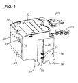
Figure 1 is a perspective view of an interlock device in accordance with an exemplary embodiment of the present invention; -
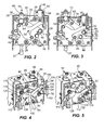
Figure 2 is a rear view of the device ofFigure 1 showing a latching assembly in a lockout position; -
Figure 3 is a rear view of the device ofFigure 1 showing the latching assembly in a reset position; -
Figure 4 is a rear perspective view of the device ofFigure 1 showing the latching assembly in a lockout position; -
Figure 5 is a rear perspective view of the device ofFigure 1 showing the latching assembly in a reset position; -
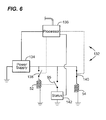
Figure 6 is a circuit diagram showing a circuit usable with the interlock device ofFigure 1 ; and -
Figure 7 is another rear perspective view of the device ofFigure 1 showing the latching assembly and a status switch. - One embodiment of the present invention concerns an interlock device for circuit protection that reduces the risk of damage to a circuit in the event of a loss of power and/or a loss of communication within the circuit.
- Referring now to
Figure 1 , an interlock in accordance with one embodiment of the present invention is illustrated generally at 10. In this embodiment, theinterlock 10 comprises aframe 12, amounting clasp 14, apower connector 16, aninterlock status connector 18 and a manual reset button assembly 20. - The
frame 12 may comprise a polymeric material and atop plate 22 is shown which may also comprise a polymeric material. Thetop plate 22 may comprise U-shaped snaps that may be fitted to theframe 12. Theframe 12 may be fastened, as shown inFigure 2 , byscrews 28 to solenoid brackets (not numbered). - The
mounting clasp 14 may comprise a steel alloy and comprises a known construction for mounting on a circuit breaker (not shown) using standard slot available for a shunt device or an under voltage device mounting. As such, the mounting clasp may be affixed to theframe 12 and compriseshook portions springs 34 and asplit portion 36. - The
power connector 16 andstatus connector 18 each comprise a known construction and are connected in circuit with a lockout circuit as will be described in more detail below in connection withFigure 6 . - The manual reset button assembly 20 comprises a
button 38 that is supported by thefront plate 24 via asuitable support structure 40 and that is interconnected with a latching assembly described in detail below. - Referring now to
Figure 2 , one exemplary embodiment of a latching assembly is shown generally at 42 and comprises any suitably strong and durable material such as a steel. Thelatching assembly 42 comprises alockout actuator 44, alockout lever 46, areset actuator 48 and areset lever 50. - The
lockout actuator 44 andreset actuator 48 are each movable, e.g., in response to energization ofsolenoid coils 52, 54 (seeFigure 6 ), which are described in more detail below. Thelockout actuator 44 may be connected with alockout actuator connector 56 via afastener 60 and with alockout trip rod 57. Thereset actuator 48 may be connected with areset actuator connector 58 via afastener 62. Thelockout actuator connector 56 comprises anactuator connector pin 64 that includes an enlargeddiameter head 66. - Referring also to
Figure 3 , thelockout lever 46 comprises anarm portion 68 and a workingportion 70. Thearm portion 68 comprises anelongated slot 72 wherethrough theactuator connector pin 64 extends and astop roller 74 for preventing improper engagement between thelockout lever 46 and resetlever 50. - The working
portion 70 comprises ahub portion 76 and afinger portion 78. Thehub portion 76 comprises anaperture 80 wherethrough alockout lever pin 82 extends. Thelockout lever pin 82 is connected with therear plate 26 of theframe 12 and functions to allow pivotable motion of thelockout lever 46. Thefinger portion 78 comprises aroller 84 that is configured to engage thereset lever 50 as described below. - Referring now to
Figure 4 , thereset actuator connector 58 comprises atab portion 86 that extends into aguide slot 88 of therear plate 26 and is disposed in contact with aterminal portion 90 of aleg portion 92 of thereset lever 50. Referring now also toFigures 3 and7 , theleg portion 92 comprises anadjustable pin 94 that functions to actuate a status switch 95 (Figure 7 ) along with a tab 96 (Figure 3 ) that is configured to be engageable by anextension 98 of amanual reset lever 100. Thestatus switch 95 comprises astatus switch lever 99 that is movable by theadjustable pin 94 and is shown in schematic diagram ofFigure 6 , described below. - The
manual reset lever 100 may be rotatably connected to asupport plate 102 via a pin 104 and biased by aspring 105. Themanual reset lever 100 comprises, along with theextension 98, astrike plate 106. Thestrike plate 106 may be configured to engage an actuator (not shown) interconnected with the manual reset button 38 (Figure 1 ). - Extending from the
leg portion 92 of thereset lever 50 is afoot portion 108 that comprises aheel 110 andtoe 112. Theheel 110 comprises anaperture 114 wherethrough apin 116 extends which is spaced and biased by aspring 118 that, at one end thereof, engages astop 120. - Turning now to
Figure 5 ,toe 112 comprises aguide portion 122 that functions to engage theroller 84 of thelockout lever 46. Theguide portion 122 comprises atooth portion 124 which functions to prevent movement of thelockout lever 46 without movement of thereset lever 50 as described in more detail below. - In operation and referring to both
Figures 4 and 5 , upon movement of thelockout actuator 44, thelockout lever 46 will be urged in a rotational direction shown byarrow 126 aboutpin 82, in turn,roller 84 will be moved along theguide 122 of thereset lever 50 and overtooth 124. Correspondingly, movement of thereset actuator 50 in the direction ofarrow 128 aboutpin 116, viaspring 118, locks theroller 84 of thelockout lever 46 againsttooth 124 of thereset lever 50 and thereby insuring that the latching assembly will be in the lockout position as shown inFigure 4 and will not move to the non-locked out position or reset position shown inFigure 5 unless the reset lever is moved in the direction ofarrow 130 shown inFigure 4 . Movement of thereset lever 50 will occur through either movement of themanual reset lever 100 via button 38 (Figure 1 ) or via movement of thereset actuator 48. - As shown in
Figures 2 and 3 , which correspond with the lockout position and reset positions of the lockingassembly 42 shown byFigures 4 and 5 described above, thelockout trip rod 57 is moved upon movement of thelockout actuator 44 between the lockout extended position as shown inFigure 2 and the non-locked out position or reset position ofFigure 3 . In the extended position, thelockout trip rod 57 will trip a circuit breaker (not shown) and prevent it from functioning. - An interrupt circuit usable with the interrupt
device 10 is shown generally at 132 inFigure 6 . The interruptcircuit 132 comprises, along withlockout solenoid 52, resetsolenoid 54 andstatus switch 95, apower supply 134, aprocessor 136, alockout switch 138, areset switch 140, and astatus circuit 142. Thelockout switch 138 may be configured to be normally open but closable in response to a command from theprocessor 136. Upon closing of thelockout switch 138, thelockout solenoid 52 will be energized by thepower supply 134 which will move the lockout actuator 44 (Figure 5 ) and the lockout lever 46 (Figure 5 ) to a lockout position as described above. Thestatus switch 95 may also be closed upon energization of thelockout solenoid coil 52 thereby enabling thestatus circuit 142 to notifyprocessor 136 of the lockout position. Thereset switch 140 may be a normally closed switch to maintain energy to thereset coil 54. Upon notification to theprocessor 136 of the lockout position, the processor may openswitch 140 thereby de-energizing thereset coil 54, in turn, moving thereset actuator 48 and thereset lever 50 to the lockout position. - While the present invention has been described in connection with what are presently considered to be the most practical and preferred embodiments, it is to be understood that the present invention is not limited to these herein disclosed embodiments. Rather, the present invention is intended to cover all of the various modifications and equivalent arrangements included within the spirit and scope of the appended claims.
Claims (13)
- An interlock mechanically interconnected with a circuit breaker, the interlock (10) toggling between a locked out position that causes the circuit breaker to trip and prevents closure thereof and a non-locked out position wherein the circuit breaker functions, the interlock (10) comprising:a frame (12);a lockout actuator (44) supported by the frame (12);a reset actuator (48) supported by the frame (12);a latching assembly (42) comprising:a lockout lever (46) responsive to movement of the lockout actuator (44) being pivotably supported by the frame (12);a lockout trip rod (57) responsive to movement of the lockout actuator (44); anda reset lever (50) being responsive to movement of the reset actuator (48) and also being pivotably supported by the frame (12), the reset lever (50) configured to prevent movement of the lockout actuator (44) without movement of the reset lever (50);wherein the lockout trip rod (57) is configured for movement between alocked out position and a non-locked out position.
- The interlock of claim 1, wherein the reset lever (50) is biased to a locked out position and the lockout actuator (44) is biased to a non-locked out position.
- The interlock of claim 1 or claim 2, further comprising a manual reset lever (100) responsive to movement of a reset button (38).
- The interlock of any one of the preceding claims, further comprising:a lockout solenoid coil (52) configured to move the lockout actuator (44) when energized; anda reset solenoid coil (54) configured to move the reset actuator (48) when energized.
- The interlock of any one of the preceding claims, further comprising:a status circuit (142) configured to monitor and provide status of whether the interlock (10) is in a lockout position.
- The interlock of claim 5, wherein the status circuit (142) comprises a status switch (95) that is actuated upon energization of the lockout solenoid coil (52).
- The interlock of any preceding claims, further comprising:a lockout switch (138) in series with the lockout solenoid coil (52);a reset switch (140) in series with the reset solenoid coil (54); anda processor (136) connected in circuit to control actuation of the lockout switch (138) and the reset switch (140).
- The interlock of claim 7, wherein the lockout switch and the reset switch are also configured to be actuated by the latching assembly.
- The interlock of any one of the preceding claims, further comprising a reset lever pin (116) and wherein the reset lever (50) comprises:a leg portion (92) interconnected to the reset actuator (48), the leg portion (92) having a flange for engaging the status switch lever (99); anda foot portion (108) extending from the leg portion (92) and the foot portion (108) comprising:a heel (110) comprising an aperture (114) to receive the reset lever pin (116) ; anda toe (112) portion comprising a guide portion (122), the guide portion (122) having a tooth portion (124).
- The interlock of claim 9, further comprising a spring (118) mounted to the reset lever pin (116) and configured to rotatably bias the leg portion (92) and, in turn, the interlock (10) to the lockout position.
- The interlock of claim 9 or claim 10, further comprising a lockout lever pin (82) and wherein the
lockout lever (46) comprises:an arm portion (68) interconnected with the lockout actuator (44); anda working portion (70) extending from the arm portion (68) and the working portion (70) comprising:a hub portion (76) comprising an aperture (80) for receiving the lockout lever pin (82);a finger portion (78) comprising a roller (84) extending therefrom and the roller (84) being configured to engage the guide portion of the reset lever (50) and wherein the roller (84) is prevented by the tooth portion (124) from allowing movement of the lockout lever (46) when in the lockout position unless the reset lever (50) is moved. - The interlock of claim 11, wherein:the lockout actuator comprises a lockout actuator connector that, in turn, comprises a lockout connector pin and wherein the arm portion comprises an elongated slot wherethrough the lockout connector lockout connector pin extends; and the reset actuator comprises a reset actuator connector that is connected between the reset actuator and the leg portion of the reset lever.
- The interlock of claim 12, wherein the frame comprises a plate comprising:a lockout actuator connector slot for receiving a free end of the lockout actuator connector; anda reset actuator connector slot for receiving a free end of the reset actuator connector.
Applications Claiming Priority (1)
| Application Number | Priority Date | Filing Date | Title |
|---|---|---|---|
| US12/102,991 US7834724B2 (en) | 2008-04-15 | 2008-04-15 | Electromechanical interlock for electrical protection devices |
Publications (3)
| Publication Number | Publication Date |
|---|---|
| EP2110839A2 true EP2110839A2 (en) | 2009-10-21 |
| EP2110839A3 EP2110839A3 (en) | 2015-03-11 |
| EP2110839B1 EP2110839B1 (en) | 2016-03-23 |
Family
ID=40801765
Family Applications (1)
| Application Number | Title | Priority Date | Filing Date |
|---|---|---|---|
| EP09157205.7A Active EP2110839B1 (en) | 2008-04-15 | 2009-04-02 | Electromechanical Interlock For Electrical Protection Devices |
Country Status (4)
| Country | Link |
|---|---|
| US (1) | US7834724B2 (en) |
| EP (1) | EP2110839B1 (en) |
| JP (1) | JP5307601B2 (en) |
| CN (1) | CN101562099B (en) |
Cited By (2)
| Publication number | Priority date | Publication date | Assignee | Title |
|---|---|---|---|---|
| CN107785196A (en) * | 2017-11-07 | 2018-03-09 | 河南森源电气股份有限公司 | The interlocking mechanism of switch cubicle and its disconnecting switch and breaker |
| WO2020200526A1 (en) * | 2019-04-05 | 2020-10-08 | Eaton Intelligent Power Limited | Circuit breaker interlock for arc quenching device |
Families Citing this family (10)
| Publication number | Priority date | Publication date | Assignee | Title |
|---|---|---|---|---|
| US7834724B2 (en) * | 2008-04-15 | 2010-11-16 | General Electric Company | Electromechanical interlock for electrical protection devices |
| US8783243B2 (en) * | 2010-10-25 | 2014-07-22 | General Electric Company | Lockout system for surface burners of a cooking appliance |
| JP5908944B2 (en) * | 2014-05-30 | 2016-04-26 | シャープ株式会社 | Power control device |
| US10147565B2 (en) | 2016-07-29 | 2018-12-04 | Mitsubishi Electric Power Products, Inc. | Vertical interlock system |
| MX390976B (en) * | 2016-09-02 | 2025-03-21 | Eaton Intelligent Power Ltd | REPLACEABLE ELECTRICAL PROTECTION SYSTEM FOR EQUIPMENT UNDER LOAD. |
| CN110085463B (en) * | 2018-01-26 | 2023-08-01 | Abb 瑞士股份有限公司 | Lock assemblies for components of power distribution systems |
| US11158473B2 (en) * | 2019-07-03 | 2021-10-26 | Eaton Intelligent Power Limited | Solid state circuit breaker button interlocking system |
| US11610751B2 (en) * | 2019-12-09 | 2023-03-21 | Leviton Manufacturing Co., Inc. | Circuit breakers incorporating reset lockout mechanisms |
| DE102019220433B4 (en) * | 2019-12-20 | 2022-03-31 | Siemens Aktiengesellschaft | Reset element and electric switch with such a reset element |
| TWI808851B (en) * | 2022-07-29 | 2023-07-11 | 陳錫瑜 | Improved device for automatic toggle switch interlock module |
Family Cites Families (23)
| Publication number | Priority date | Publication date | Assignee | Title |
|---|---|---|---|---|
| US1814826A (en) * | 1928-04-27 | 1931-07-14 | Gen Electric | Electric switch |
| US1953789A (en) * | 1932-09-20 | 1934-04-03 | Gen Electric | Operating mechanism |
| US2269741A (en) * | 1941-02-27 | 1942-01-13 | Cutler Hammer Inc | Electric switch |
| US2452065A (en) * | 1943-12-30 | 1948-10-26 | Gen Electric | Electric switch |
| US2446299A (en) * | 1944-02-14 | 1948-08-03 | Guardian Electric Mfg Co | Interlocking relay |
| US4001739A (en) * | 1975-10-30 | 1977-01-04 | General Electric Company | Circuit breaker with bell alarm and breaker lockout accessory |
| JPS5646292Y2 (en) * | 1975-12-25 | 1981-10-29 | ||
| USRE34396E (en) * | 1984-08-16 | 1993-10-05 | Helmut Letzel | Safety interlock switching device for protecting equipment |
| FR2570872B1 (en) * | 1984-09-27 | 1988-08-26 | Telemecanique Electrique | VARIABLE COMPOSITION SWITCHING DEVICE |
| EP0237607A1 (en) * | 1986-03-21 | 1987-09-23 | Square D Company (Deutschland) Gmbh | Contactor |
| JPS63192638U (en) * | 1987-05-29 | 1988-12-12 | ||
| CN1010148B (en) * | 1987-09-22 | 1990-10-24 | 斯奎尔·D·强电股份有限公司 | Contactor |
| JPH074757Y2 (en) * | 1987-10-26 | 1995-02-01 | 株式会社東芝 | Operating device for gas insulated switch |
| ES2035843T3 (en) * | 1987-11-25 | 1993-05-01 | Square D Company (Deutschland) Gmbh | CONTACTOR. |
| JPH0648719Y2 (en) * | 1988-01-11 | 1994-12-12 | 日新電機株式会社 | Automatic locking device for switch operating mechanism |
| US5821876A (en) * | 1991-10-08 | 1998-10-13 | Square D Company | Communication interface for bus connected circuit breakers |
| US5300905A (en) * | 1992-10-19 | 1994-04-05 | Ford Motor Company | Electrical power disconnect switch with both manual and electrical trip operation |
| DE69423087T2 (en) * | 1994-01-17 | 2000-11-02 | Circuit Breaker Industries Ltd., Elandsfontein | Circuit breaker operating device |
| US6107702A (en) * | 1999-03-29 | 2000-08-22 | Siemens Energy & Automation, Inc. | Electrical control module for a circuit breaker stored energy operator assembly |
| US20020135232A1 (en) * | 2000-10-13 | 2002-09-26 | Xantrex International | Method and apparatus for distributing electric power |
| FR2846470B1 (en) * | 2002-10-28 | 2005-03-04 | Schneider Electric Ind Sas | ELECTRICAL SWITCHING DEVICE, RELAY AND ELECTRICAL DEVICE COMPRISING SUCH A DEVICE |
| KR100424668B1 (en) * | 2003-10-22 | 2004-03-24 | 주식회사 기성기전 | Electromagnetic switch |
| US7834724B2 (en) * | 2008-04-15 | 2010-11-16 | General Electric Company | Electromechanical interlock for electrical protection devices |
-
2008
- 2008-04-15 US US12/102,991 patent/US7834724B2/en active Active
-
2009
- 2009-04-02 EP EP09157205.7A patent/EP2110839B1/en active Active
- 2009-04-08 JP JP2009093493A patent/JP5307601B2/en active Active
- 2009-04-15 CN CN2009101328737A patent/CN101562099B/en active Active
Cited By (3)
| Publication number | Priority date | Publication date | Assignee | Title |
|---|---|---|---|---|
| CN107785196A (en) * | 2017-11-07 | 2018-03-09 | 河南森源电气股份有限公司 | The interlocking mechanism of switch cubicle and its disconnecting switch and breaker |
| CN107785196B (en) * | 2017-11-07 | 2021-01-05 | 河南森源电气股份有限公司 | Switch cabinet and interlocking mechanism of isolating switch and circuit breaker thereof |
| WO2020200526A1 (en) * | 2019-04-05 | 2020-10-08 | Eaton Intelligent Power Limited | Circuit breaker interlock for arc quenching device |
Also Published As
| Publication number | Publication date |
|---|---|
| JP2009259812A (en) | 2009-11-05 |
| US20090255787A1 (en) | 2009-10-15 |
| CN101562099B (en) | 2013-11-13 |
| CN101562099A (en) | 2009-10-21 |
| JP5307601B2 (en) | 2013-10-02 |
| US7834724B2 (en) | 2010-11-16 |
| EP2110839B1 (en) | 2016-03-23 |
| EP2110839A3 (en) | 2015-03-11 |
Similar Documents
| Publication | Publication Date | Title |
|---|---|---|
| US7834724B2 (en) | Electromechanical interlock for electrical protection devices | |
| US9799476B2 (en) | Remote operated circuit breaker | |
| US5629662A (en) | Low energy memory metal actuated latch | |
| EP1916691B1 (en) | Automatic reset and self-test device particularly for residual current operated circuit breakers and the like | |
| JPS61121231A (en) | Breaker | |
| CA2464165C (en) | Remotely controllable circuit breaker including bypass magnet circuit | |
| CA2425714C (en) | Externally controllable circuit breaker | |
| US12512288B2 (en) | Electrical switching apparatus and trip assembly therefor | |
| AU2004201318B2 (en) | Circuit breaker mechanism including mechanism for breaking tack weld | |
| CN102097263B (en) | Remotely controlled switchgear and power distribution device provided with such switchgear | |
| CA2437111C (en) | Circuit breaker | |
| US6469600B1 (en) | Remote control circuit breaker with a by-pass lead | |
| US8093964B2 (en) | Add-on trip module for multi-pole circuit breaker | |
| KR101084402B1 (en) | Interlock | |
| US3129358A (en) | Cold load pick-up apparatus for an automatic recloser | |
| US20240242911A1 (en) | Resetting rcd mechanism by the handle | |
| EP1261010A1 (en) | Auxiliary device for a magnetothermal circuit breaker | |
| AU2002226629A1 (en) | Circuit breaker |
Legal Events
| Date | Code | Title | Description |
|---|---|---|---|
| PUAI | Public reference made under article 153(3) epc to a published international application that has entered the european phase |
Free format text: ORIGINAL CODE: 0009012 |
|
| AK | Designated contracting states |
Kind code of ref document: A2 Designated state(s): AT BE BG CH CY CZ DE DK EE ES FI FR GB GR HR HU IE IS IT LI LT LU LV MC MK MT NL NO PL PT RO SE SI SK TR |
|
| PUAL | Search report despatched |
Free format text: ORIGINAL CODE: 0009013 |
|
| AK | Designated contracting states |
Kind code of ref document: A3 Designated state(s): AT BE BG CH CY CZ DE DK EE ES FI FR GB GR HR HU IE IS IT LI LT LU LV MC MK MT NL NO PL PT RO SE SI SK TR |
|
| RIC1 | Information provided on ipc code assigned before grant |
Ipc: H01H 71/62 20060101ALI20150204BHEP Ipc: H01H 71/68 20060101ALI20150204BHEP Ipc: H01H 71/12 20060101AFI20150204BHEP |
|
| 17P | Request for examination filed |
Effective date: 20150911 |
|
| GRAP | Despatch of communication of intention to grant a patent |
Free format text: ORIGINAL CODE: EPIDOSNIGR1 |
|
| RBV | Designated contracting states (corrected) |
Designated state(s): AT BE BG CH CY CZ DE DK EE ES FI FR GB GR HR HU IE IS IT LI LT LU LV MC MK MT NL NO PL PT RO SE SI SK TR |
|
| RIC1 | Information provided on ipc code assigned before grant |
Ipc: H01H 71/12 20060101AFI20151006BHEP Ipc: H01H 71/62 20060101ALI20151006BHEP Ipc: H01H 71/68 20060101ALI20151006BHEP Ipc: H01H 71/66 20060101ALN20151006BHEP |
|
| INTG | Intention to grant announced |
Effective date: 20151022 |
|
| RIN1 | Information on inventor provided before grant (corrected) |
Inventor name: NEWASE, YATIN VILAS Inventor name: GUPTA, SIMHADRI RAMALINGESWARA RAO Inventor name: RANE, MAHESH JAYWANT |
|
| GRAS | Grant fee paid |
Free format text: ORIGINAL CODE: EPIDOSNIGR3 |
|
| GRAA | (expected) grant |
Free format text: ORIGINAL CODE: 0009210 |
|
| AK | Designated contracting states |
Kind code of ref document: B1 Designated state(s): AT BE BG CH CY CZ DE DK EE ES FI FR GB GR HR HU IE IS IT LI LT LU LV MC MK MT NL NO PL PT RO SE SI SK TR |
|
| REG | Reference to a national code |
Ref country code: GB Ref legal event code: FG4D |
|
| REG | Reference to a national code |
Ref country code: CH Ref legal event code: EP |
|
| REG | Reference to a national code |
Ref country code: AT Ref legal event code: REF Ref document number: 783877 Country of ref document: AT Kind code of ref document: T Effective date: 20160415 |
|
| REG | Reference to a national code |
Ref country code: IE Ref legal event code: FG4D |
|
| REG | Reference to a national code |
Ref country code: DE Ref legal event code: R096 Ref document number: 602009036941 Country of ref document: DE |
|
| REG | Reference to a national code |
Ref country code: LT Ref legal event code: MG4D |
|
| REG | Reference to a national code |
Ref country code: NL Ref legal event code: MP Effective date: 20160323 |
|
| PG25 | Lapsed in a contracting state [announced via postgrant information from national office to epo] |
Ref country code: FI Free format text: LAPSE BECAUSE OF FAILURE TO SUBMIT A TRANSLATION OF THE DESCRIPTION OR TO PAY THE FEE WITHIN THE PRESCRIBED TIME-LIMIT Effective date: 20160323 Ref country code: GR Free format text: LAPSE BECAUSE OF FAILURE TO SUBMIT A TRANSLATION OF THE DESCRIPTION OR TO PAY THE FEE WITHIN THE PRESCRIBED TIME-LIMIT Effective date: 20160624 Ref country code: NO Free format text: LAPSE BECAUSE OF FAILURE TO SUBMIT A TRANSLATION OF THE DESCRIPTION OR TO PAY THE FEE WITHIN THE PRESCRIBED TIME-LIMIT Effective date: 20160623 |
|
| REG | Reference to a national code |
Ref country code: AT Ref legal event code: MK05 Ref document number: 783877 Country of ref document: AT Kind code of ref document: T Effective date: 20160323 |
|
| PG25 | Lapsed in a contracting state [announced via postgrant information from national office to epo] |
Ref country code: LT Free format text: LAPSE BECAUSE OF FAILURE TO SUBMIT A TRANSLATION OF THE DESCRIPTION OR TO PAY THE FEE WITHIN THE PRESCRIBED TIME-LIMIT Effective date: 20160323 Ref country code: LV Free format text: LAPSE BECAUSE OF FAILURE TO SUBMIT A TRANSLATION OF THE DESCRIPTION OR TO PAY THE FEE WITHIN THE PRESCRIBED TIME-LIMIT Effective date: 20160323 Ref country code: BE Free format text: LAPSE BECAUSE OF NON-PAYMENT OF DUE FEES Effective date: 20160430 Ref country code: SE Free format text: LAPSE BECAUSE OF FAILURE TO SUBMIT A TRANSLATION OF THE DESCRIPTION OR TO PAY THE FEE WITHIN THE PRESCRIBED TIME-LIMIT Effective date: 20160323 Ref country code: NL Free format text: LAPSE BECAUSE OF FAILURE TO SUBMIT A TRANSLATION OF THE DESCRIPTION OR TO PAY THE FEE WITHIN THE PRESCRIBED TIME-LIMIT Effective date: 20160323 |
|
| PG25 | Lapsed in a contracting state [announced via postgrant information from national office to epo] |
Ref country code: PL Free format text: LAPSE BECAUSE OF FAILURE TO SUBMIT A TRANSLATION OF THE DESCRIPTION OR TO PAY THE FEE WITHIN THE PRESCRIBED TIME-LIMIT Effective date: 20160323 Ref country code: IS Free format text: LAPSE BECAUSE OF FAILURE TO SUBMIT A TRANSLATION OF THE DESCRIPTION OR TO PAY THE FEE WITHIN THE PRESCRIBED TIME-LIMIT Effective date: 20160723 Ref country code: EE Free format text: LAPSE BECAUSE OF FAILURE TO SUBMIT A TRANSLATION OF THE DESCRIPTION OR TO PAY THE FEE WITHIN THE PRESCRIBED TIME-LIMIT Effective date: 20160323 |
|
| PG25 | Lapsed in a contracting state [announced via postgrant information from national office to epo] |
Ref country code: CZ Free format text: LAPSE BECAUSE OF FAILURE TO SUBMIT A TRANSLATION OF THE DESCRIPTION OR TO PAY THE FEE WITHIN THE PRESCRIBED TIME-LIMIT Effective date: 20160323 Ref country code: RO Free format text: LAPSE BECAUSE OF FAILURE TO SUBMIT A TRANSLATION OF THE DESCRIPTION OR TO PAY THE FEE WITHIN THE PRESCRIBED TIME-LIMIT Effective date: 20160323 Ref country code: AT Free format text: LAPSE BECAUSE OF FAILURE TO SUBMIT A TRANSLATION OF THE DESCRIPTION OR TO PAY THE FEE WITHIN THE PRESCRIBED TIME-LIMIT Effective date: 20160323 Ref country code: PT Free format text: LAPSE BECAUSE OF FAILURE TO SUBMIT A TRANSLATION OF THE DESCRIPTION OR TO PAY THE FEE WITHIN THE PRESCRIBED TIME-LIMIT Effective date: 20160725 Ref country code: SK Free format text: LAPSE BECAUSE OF FAILURE TO SUBMIT A TRANSLATION OF THE DESCRIPTION OR TO PAY THE FEE WITHIN THE PRESCRIBED TIME-LIMIT Effective date: 20160323 Ref country code: ES Free format text: LAPSE BECAUSE OF FAILURE TO SUBMIT A TRANSLATION OF THE DESCRIPTION OR TO PAY THE FEE WITHIN THE PRESCRIBED TIME-LIMIT Effective date: 20160323 |
|
| REG | Reference to a national code |
Ref country code: CH Ref legal event code: PL |
|
| PG25 | Lapsed in a contracting state [announced via postgrant information from national office to epo] |
Ref country code: BE Free format text: LAPSE BECAUSE OF FAILURE TO SUBMIT A TRANSLATION OF THE DESCRIPTION OR TO PAY THE FEE WITHIN THE PRESCRIBED TIME-LIMIT Effective date: 20160323 Ref country code: IT Free format text: LAPSE BECAUSE OF FAILURE TO SUBMIT A TRANSLATION OF THE DESCRIPTION OR TO PAY THE FEE WITHIN THE PRESCRIBED TIME-LIMIT Effective date: 20160323 |
|
| REG | Reference to a national code |
Ref country code: DE Ref legal event code: R097 Ref document number: 602009036941 Country of ref document: DE |
|
| REG | Reference to a national code |
Ref country code: IE Ref legal event code: MM4A |
|
| PLBE | No opposition filed within time limit |
Free format text: ORIGINAL CODE: 0009261 |
|
| REG | Reference to a national code |
Ref country code: FR Ref legal event code: ST Effective date: 20161230 |
|
| STAA | Information on the status of an ep patent application or granted ep patent |
Free format text: STATUS: NO OPPOSITION FILED WITHIN TIME LIMIT |
|
| PG25 | Lapsed in a contracting state [announced via postgrant information from national office to epo] |
Ref country code: CH Free format text: LAPSE BECAUSE OF NON-PAYMENT OF DUE FEES Effective date: 20160430 Ref country code: FR Free format text: LAPSE BECAUSE OF NON-PAYMENT OF DUE FEES Effective date: 20160523 Ref country code: LI Free format text: LAPSE BECAUSE OF NON-PAYMENT OF DUE FEES Effective date: 20160430 Ref country code: DK Free format text: LAPSE BECAUSE OF FAILURE TO SUBMIT A TRANSLATION OF THE DESCRIPTION OR TO PAY THE FEE WITHIN THE PRESCRIBED TIME-LIMIT Effective date: 20160323 |
|
| PG25 | Lapsed in a contracting state [announced via postgrant information from national office to epo] |
Ref country code: BG Free format text: LAPSE BECAUSE OF FAILURE TO SUBMIT A TRANSLATION OF THE DESCRIPTION OR TO PAY THE FEE WITHIN THE PRESCRIBED TIME-LIMIT Effective date: 20160623 |
|
| 26N | No opposition filed |
Effective date: 20170102 |
|
| GBPC | Gb: european patent ceased through non-payment of renewal fee |
Effective date: 20160623 |
|
| PG25 | Lapsed in a contracting state [announced via postgrant information from national office to epo] |
Ref country code: IE Free format text: LAPSE BECAUSE OF NON-PAYMENT OF DUE FEES Effective date: 20160402 Ref country code: SI Free format text: LAPSE BECAUSE OF FAILURE TO SUBMIT A TRANSLATION OF THE DESCRIPTION OR TO PAY THE FEE WITHIN THE PRESCRIBED TIME-LIMIT Effective date: 20160323 Ref country code: GB Free format text: LAPSE BECAUSE OF NON-PAYMENT OF DUE FEES Effective date: 20160623 |
|
| PG25 | Lapsed in a contracting state [announced via postgrant information from national office to epo] |
Ref country code: HU Free format text: LAPSE BECAUSE OF FAILURE TO SUBMIT A TRANSLATION OF THE DESCRIPTION OR TO PAY THE FEE WITHIN THE PRESCRIBED TIME-LIMIT; INVALID AB INITIO Effective date: 20090402 Ref country code: CY Free format text: LAPSE BECAUSE OF FAILURE TO SUBMIT A TRANSLATION OF THE DESCRIPTION OR TO PAY THE FEE WITHIN THE PRESCRIBED TIME-LIMIT Effective date: 20160323 |
|
| PG25 | Lapsed in a contracting state [announced via postgrant information from national office to epo] |
Ref country code: TR Free format text: LAPSE BECAUSE OF FAILURE TO SUBMIT A TRANSLATION OF THE DESCRIPTION OR TO PAY THE FEE WITHIN THE PRESCRIBED TIME-LIMIT Effective date: 20160323 Ref country code: MC Free format text: LAPSE BECAUSE OF FAILURE TO SUBMIT A TRANSLATION OF THE DESCRIPTION OR TO PAY THE FEE WITHIN THE PRESCRIBED TIME-LIMIT Effective date: 20160323 Ref country code: MK Free format text: LAPSE BECAUSE OF FAILURE TO SUBMIT A TRANSLATION OF THE DESCRIPTION OR TO PAY THE FEE WITHIN THE PRESCRIBED TIME-LIMIT Effective date: 20160323 Ref country code: LU Free format text: LAPSE BECAUSE OF NON-PAYMENT OF DUE FEES Effective date: 20160402 Ref country code: HR Free format text: LAPSE BECAUSE OF FAILURE TO SUBMIT A TRANSLATION OF THE DESCRIPTION OR TO PAY THE FEE WITHIN THE PRESCRIBED TIME-LIMIT Effective date: 20160323 Ref country code: MT Free format text: LAPSE BECAUSE OF NON-PAYMENT OF DUE FEES Effective date: 20160430 |
|
| REG | Reference to a national code |
Ref country code: DE Ref legal event code: R081 Ref document number: 602009036941 Country of ref document: DE Owner name: ABB S.P.A., IT Free format text: FORMER OWNER: GENERAL ELECTRIC COMPANY, SCHENECTADY, NY, US Ref country code: DE Ref legal event code: R081 Ref document number: 602009036941 Country of ref document: DE Owner name: ABB SCHWEIZ AG, CH Free format text: FORMER OWNER: GENERAL ELECTRIC COMPANY, SCHENECTADY, N.Y., US Ref country code: DE Ref legal event code: R081 Ref document number: 602009036941 Country of ref document: DE Owner name: ABB SCHWEIZ AG, CH Free format text: FORMER OWNER: GENERAL ELECTRIC COMPANY, SCHENECTADY, NY, US |
|
| REG | Reference to a national code |
Ref country code: DE Ref legal event code: R081 Ref document number: 602009036941 Country of ref document: DE Owner name: ABB S.P.A., IT Free format text: FORMER OWNER: ABB SCHWEIZ AG, BADEN, CH Ref country code: DE Ref legal event code: R082 Ref document number: 602009036941 Country of ref document: DE Representative=s name: DENNEMEYER & ASSOCIATES S.A., DE |
|
| PGFP | Annual fee paid to national office [announced via postgrant information from national office to epo] |
Ref country code: DE Payment date: 20250422 Year of fee payment: 17 |