EP2110714A2 - Developer material holding apparatus - Google Patents
Developer material holding apparatus Download PDFInfo
- Publication number
- EP2110714A2 EP2110714A2 EP09156257A EP09156257A EP2110714A2 EP 2110714 A2 EP2110714 A2 EP 2110714A2 EP 09156257 A EP09156257 A EP 09156257A EP 09156257 A EP09156257 A EP 09156257A EP 2110714 A2 EP2110714 A2 EP 2110714A2
- Authority
- EP
- European Patent Office
- Prior art keywords
- openings
- developer material
- toner
- shutter
- holding apparatus
- Prior art date
- Legal status (The legal status is an assumption and is not a legal conclusion. Google has not performed a legal analysis and makes no representation as to the accuracy of the status listed.)
- Withdrawn
Links
- 239000000463 material Substances 0.000 title claims abstract description 38
- 238000000034 method Methods 0.000 claims description 16
- 238000007599 discharging Methods 0.000 description 15
- 230000004048 modification Effects 0.000 description 8
- 238000012986 modification Methods 0.000 description 8
- 238000007789 sealing Methods 0.000 description 7
- 230000032258 transport Effects 0.000 description 3
- 239000002390 adhesive tape Substances 0.000 description 2
- 238000004140 cleaning Methods 0.000 description 2
- 239000003086 colorant Substances 0.000 description 2
- 238000010276 construction Methods 0.000 description 2
- 230000002787 reinforcement Effects 0.000 description 2
- 238000002474 experimental method Methods 0.000 description 1
- 230000001771 impaired effect Effects 0.000 description 1
- 230000000977 initiatory effect Effects 0.000 description 1
- 239000002245 particle Substances 0.000 description 1
- 239000000843 powder Substances 0.000 description 1
Images



Classifications
-
- G—PHYSICS
- G03—PHOTOGRAPHY; CINEMATOGRAPHY; ANALOGOUS TECHNIQUES USING WAVES OTHER THAN OPTICAL WAVES; ELECTROGRAPHY; HOLOGRAPHY
- G03G—ELECTROGRAPHY; ELECTROPHOTOGRAPHY; MAGNETOGRAPHY
- G03G15/00—Apparatus for electrographic processes using a charge pattern
- G03G15/06—Apparatus for electrographic processes using a charge pattern for developing
- G03G15/08—Apparatus for electrographic processes using a charge pattern for developing using a solid developer, e.g. powder developer
- G03G15/0822—Arrangements for preparing, mixing, supplying or dispensing developer
- G03G15/0877—Arrangements for metering and dispensing developer from a developer cartridge into the development unit
- G03G15/0881—Sealing of developer cartridges
- G03G15/0886—Sealing of developer cartridges by mechanical means, e.g. shutter, plug
-
- G—PHYSICS
- G03—PHOTOGRAPHY; CINEMATOGRAPHY; ANALOGOUS TECHNIQUES USING WAVES OTHER THAN OPTICAL WAVES; ELECTROGRAPHY; HOLOGRAPHY
- G03G—ELECTROGRAPHY; ELECTROPHOTOGRAPHY; MAGNETOGRAPHY
- G03G15/00—Apparatus for electrographic processes using a charge pattern
- G03G15/06—Apparatus for electrographic processes using a charge pattern for developing
- G03G15/08—Apparatus for electrographic processes using a charge pattern for developing using a solid developer, e.g. powder developer
- G03G15/0822—Arrangements for preparing, mixing, supplying or dispensing developer
- G03G15/0848—Arrangements for testing or measuring developer properties or quality, e.g. charge, size, flowability
- G03G15/0849—Detection or control means for the developer concentration
- G03G15/0855—Detection or control means for the developer concentration the concentration being measured by optical means
-
- G—PHYSICS
- G03—PHOTOGRAPHY; CINEMATOGRAPHY; ANALOGOUS TECHNIQUES USING WAVES OTHER THAN OPTICAL WAVES; ELECTROGRAPHY; HOLOGRAPHY
- G03G—ELECTROGRAPHY; ELECTROPHOTOGRAPHY; MAGNETOGRAPHY
- G03G15/00—Apparatus for electrographic processes using a charge pattern
- G03G15/06—Apparatus for electrographic processes using a charge pattern for developing
- G03G15/08—Apparatus for electrographic processes using a charge pattern for developing using a solid developer, e.g. powder developer
- G03G15/0822—Arrangements for preparing, mixing, supplying or dispensing developer
- G03G15/0865—Arrangements for supplying new developer
-
- G—PHYSICS
- G03—PHOTOGRAPHY; CINEMATOGRAPHY; ANALOGOUS TECHNIQUES USING WAVES OTHER THAN OPTICAL WAVES; ELECTROGRAPHY; HOLOGRAPHY
- G03G—ELECTROGRAPHY; ELECTROPHOTOGRAPHY; MAGNETOGRAPHY
- G03G2215/00—Apparatus for electrophotographic processes
- G03G2215/06—Developing structures, details
- G03G2215/066—Toner cartridge or other attachable and detachable container for supplying developer material to replace the used material
- G03G2215/0663—Toner cartridge or other attachable and detachable container for supplying developer material to replace the used material having a longitudinal rotational axis, around which at least one part is rotated when mounting or using the cartridge
- G03G2215/0665—Generally horizontally mounting of said toner cartridge parallel to its longitudinal rotational axis
- G03G2215/067—Toner discharging opening covered by arcuate shutter
Definitions
- the present invention relates to a developer material holding apparatus, a process cartridge to which the developer material holding apparatus is attached, and an image forming apparatus to which the process cartridge is attached.
- a toner cartridge holds a developer material or toner therein, and is detachably attached to a process cartridge of the image forming apparatus.
- the toner cartridge includes a casing that defines a toner chamber, and a shutter that is rotatably accommodated in the casing.
- the casing includes a toner discharging opening formed therein, and the shutter includes another toner discharging opening formed therein.
- the openings are substantially equal in size.
- the conventional toner cartridge is mounted on top of the process cartridge, so that the toner is discharged through the toner discharging opening formed in the casing into a toner receiving opening formed in the process cartridge.
- the whole toner in the toner cartridge directly exerts pressure on the toner in the process cartridge, so that the toner in the process cartridge is compressed.
- a developer material holding apparatus holds a developer.
- a body holds a developer material and includes a first opening (25+26, 44a-44c) through which the developer material is discharged.
- a shutter (23) is assembled to the body, and is movable either to an opening position where the developer material is discharged from the body or to a closing position where the developer material is not discharged from the body.
- the shutter (23) includes a second opening (27a-27c, 45+47) such that when the shutter (23) is at the opening position, the second opening is in alignment with the first opening. At least one of the first opening and the second opening is in the form a mesh including a plurality of openings (26, 47).
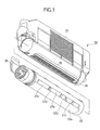
- Fig. 1 is an exploded perspective view of a developer material holding apparatus or a toner cartridge 20 of a first embodiment.
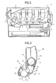
- Fig. 2 illustrates a general configuration of an image forming apparatus 1 in which the toner cartridge 20 is used.
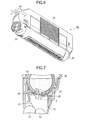
- Fig. 3 is a cross sectional view of the toner cartridge 20 attached to a developing unit 13.
- the image forming apparatus 1 includes a medium cassette 2 that holds a stack of print media therein, a transport path 3 in which the print medium is transported, print engines or process cartridges 4 that form images of corresponding colors (black, yellow, magenta, and cyan) in accordance with print data, transfer rollers 5 that transfer the corresponding color images onto which the print medium, a transfer belt 6 that transports the print medium through the print process cartridges 4, and a fixing unit where the images are fused into the print medium.
- Four of the process cartridges 4 are employed, and are of the identical configuration, differing only in color.
- the print medium Upon initiation of a print operation, the print medium is advanced by a feeding roller 8 from the medium cassette 2, and is then transported in the transport path 3 to the print process cartridges 4.
- Each print process cartridge 4 forms a toner image of a corresponding color in accordance with print data.
- the toner images of the respective colors are formed in timed relation with the transportation of the print medium, and are transferred onto the print medium in sequence.
- the print medium is further advanced to the fixing unit 7 where the toner images on the print medium are fused into a permanent image.
- the print medium is then transported to a stacker defined on top of the image forming apparatus 1.
- each process cartridge 4 includes a photoconductive drum 10, a charging roller 11, a light emitting diode (LED) head 12, a developing unit 13, and a cleaning section 14.
- the charging roller 11 uniformly charges the entire circumferential surface of the photoconductive drum 10.
- the LED head 12 illuminates the charged surface of the photoconductive drum 10 in accordance with the print data.
- the cleaning section 14 removes the residual toner remaining on the photoconductive drum 10.
- the developing unit 13 includes a developing roller 15 and a supplying roller 16.
- the charging roller 11 rotates in pressure contact with the photoconductive drum 10.
- a developing blade 17 is in pressure contact with the developing roller 15, and forms a thin layer of toner on the developing roller 15.
- the supplying roller 16 rotates in pressure contact with the developing roller 15, and supplies the toner in the toner reservoir 18 above the supplying roller 16 to the developing roller 15.
- a cartridge receiving portion 19 is formed on top of the developing unit 13, and receives the toner cartridge 20 attached thereto.
- the cartridge receiving portion 19 includes a toner receiving opening 21 and a toner reservoir 18 into which the toner is discharged from the toner cartridge 20.
- the toner cartridge 20 includes a body or a casing 22 and a shutter 23.
- the shutter 23 is assembled through a mounting portion 24 into the casing 22.
- the casing 22 includes a toner discharging opening (first opening ) or a mesh 25 of a plurality of mesh openings 26 formed in its bottom.
- the mesh 25 faces the toner receiving opening 21.
- the shutter 23 is then rotated to an opening position, moving from its closing position ( Fig. 5 ) to its opening position ( Fig. 6 ).
- the mesh 25 includes a plurality of mesh openings 26 of equal size formed therein.
- the toner particles are discharged from the toner cartridge 20 through the mesh openings 26.
- Fig. 4 illustrates the mesh openings 26 which are square holes and are arranged in a staggered fashion.
- the mesh openings 26 are arranged in a plurality of rows extending in a longitudinal direction of the toner cartridge 20 such that the mesh openings 26 in one of adjacent rows are staggered with respect to the openings in the other of the adjacent rows.
- the shutter 23 is generally in the shape of a hollow cylinder, and includes second openings or openings 27a-27c arranged one behind the other in a longitudinal direction of the shutter 23.
- the openings 27a-27c are partitioned by reinforcements 27d.
- Each opening 27a-27c is much larger than each mesh opening 26.
- An operation lever 28 is formed at one longitudinal end of the shutter 23 as shown in Fig. 1 . Once the toner cartridge 20 has been attached to the developing unit 13, a user may operate the operation lever 28 to rotate the shutter 23 relative to the mounting portion 24, causing the openings 27a-27c to face the mesh 25.
- a sealing sponge 23a is bonded to an outer cylindrical surface of the shutter 23 by means of a double side adhesive tape. When the shutter 23 is at the closing position, the sealing sponge 23a surrounds the mesh 25. The sealing sponge 23a seals the gap between the shutter 23 and the inner surface of the casing 22, preventing the toner from leaking from the toner cartridge 20 through the gap.
- Fig. 5 illustrates the toner cartridge 20 when the shutter 23 has been attached to the casing 22 and is at the closing position. With the shutter 23 positioned at the closing position, the toner cartridge 20 is attached to the cartridge receiving portion 19 of the developing unit 13.
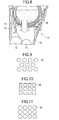
- Fig. 6 illustrates the toner cartridge 20 when the shutter 23 is at the opening position.
- the operation lever 28 rotates the operation lever 28 in a direction shown by arrow X ( Fig. 6 ) after the toner cartridge 20 has been received by the cartridge receiving portion 19, the shutter 23 moves to the opening position, where the openings 27a-27c directly face the mesh 25 as shown in Fig. 3 . This allows the toner to be discharged from the toner cartridge 20 into the developing unit 13.
- the toner flows out of the toner cartridge 20 through the openings 27a-27c and toner discharge opening 25 into the toner receiving opening 21 of the developing unit 13. Thus, the toner is directed into the toner reservoir 18.
- Fig. 7 illustrates when the toner is being supplied into the toner reservoir 18.
- Fig. 8 illustrates a conventional toner cartridge when the toner is being supplied into the toner reservoir 18.
- the opening 28 of the shutter, toner discharging opening 29, and toner receiving opening 21 are wide open.
- the whole toner in the toner cartridge directly exerts pressure on the toner held in the toner reservoir 18.
- the mesh 25 of the casing 22 of the first embodiment includes a plurality of mesh openings 26. Therefore, a part of the pressure of the whole toner in the toner cartridge 20 is received by the portions of the casing 22 that define the mesh openings 26, preventing the pressure of the whole toner in the toner cartridge 20 from being directly exerted on the toner in the toner reservoir 18. This minimizes the decrease in the flowability of the toner in the toner reservoir 18, being advantageous to maintain good print quality.
- the mesh openings 26 forming a mesh as a whole is advantageous in that the mechanical strength or rigidity of the casing 22 in the vicinity of the openings 27a-27c is improved, preventing the casing 22 from being deformed by external forces as well as preventing the toner from leaking through the gap between the mesh 25 and the shutter 23.
- Figs. 9-10 illustrate modifications to the mesh openings 26.
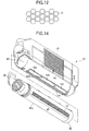
- Figs. 11 and 12 illustrate additional modifications to the mesh openings 26.
- the mesh openings 26 have been described as having a size of 4 mm ⁇ 4 mm. However, the mesh openings 26 having a size in the range of 1 mm ⁇ 1 mm to 6 mm ⁇ 6 mm also provide substantially the same advantages as the openings having a size of 4 mm ⁇ 4 mm. In addition, the mesh openings 26 are arranged in a staggered configuration. Instead, round or circular openings 30 ( Fig. 9 ) may be used in place of the square mesh openings 26. Still alternatively, square mesh openings 26 may be arranged on grids as shown in Fig. 10 or the round openings 30 may be arranged on grids as shown in Fig. 11 . Yet alternatively, polygonal openings or hexagonal openings 31 may be arranged in a honeycomb pattern as shown in Fig. 12 .
- Figs. 13A and 13B illustrate a modification to the shutter 23. While the first embodiment has been described with respect to the shutter 23 having the opening 27a-27c, the shutter may not be a substantially hollow cylinder but may be a merely arcuate wall or a partially cylindrical wall encompassing a predetermined angle ⁇ of circumference without any opening formed in the wall as shown in Figs. 13A and 13B .
- Fig. 14 is an exploded perspective view of a toner cartridge 40 of a second embodiment.
- the toner cartridge 40 includes a body or a casing 41 and a shutter 42.
- the shutter 42 is rotatably attached into the casing 41 through a shutter receiving opening 43.
- the casing 41 includes first openings or toner discharging openings 44a-44c formed in its bottom wall of the shutter receiving opening 43.
- the toner discharging openings 44a-44c differ from the toner discharging opening or the mesh 25 of the first embodiment, but are much larger openings partitioned by a plurality of reinforcements 44d.
- the shutter 42 is generally in the shape of a hollow cylinder having second opening or a mesh 45 in which a plurality of mesh openings 47 are formed, the holes extending as a whole in a longitudinal direction of the shutter 42.
- the shutter 42 includes an operation lever 28 formed at one longitudinal end of the shutter 42. When a user operates the operation lever 28 to an opening position after the shutter 28 has been attached to a developing unit 13, the shutter 42 rotates to the opening position where the mesh 45 directly face the toner discharging openings 44a-44c.
- a sealing sponge 42a is bonded to an outer cylindrical surface of the shutter 42 by means of a double side adhesive tape. When the shutter 42 is at a closing position, the sealing sponge surrounds the toner discharging opening 44a-44c.
- the sealing sponge 42a seals the gap between the shutter 42 and the inner surface of the casing 22, preventing the toner from leaking from the toner cartridge 40 through the gap.
- the mesh 45 formed in the shutter 42 are in the shape of a mesh having small mesh openings 47 such that the toner is discharged from the toner cartridge 40 through the small mesh openings 47.
- the small mesh openings 47 are arranged in a plurality of rows such that the mesh openings 47 in one of adj acent rows are staggered with respect to the mesh openings 47 in the other of the adjacent rows.
- the toner discharge openings 44a-44c directly face a toner receiving openings 21 ( Fig. 17 ).
- Fig. 15 illustrates the toner cartridge 40 when the shutter 42 has been assembled to the casing 41 and is at the closing position.
- Fig. 16 illustrates the toner cartridge 40 when the operation lever 28 has been rotated to the opening position.
- Fig. 17 illustrates when the toner is being supplied from the toner cartridge 40 into the developing unit 13.
- the toner cartridge 40 With the shutter 42 at the closing position, the toner cartridge 40 is mounted to the cartridge receiving portion 19 of the developing unit 13 ( Fig. 3 ). After the toner cartridge 40 has been attached to the developing unit 13, if the user operates the operation lever 28 to rotate in a direction shown by arrow Y ( Fig. 16 ), the shutter 42 is opened, so that the mesh 45 directly faces the toner discharging opening 44a-44c of the casing 41 ( Fig. 17 ). Thus, the toner may be supplied from the toner cartridge 40 into a toner reservoir 18 of the developing unit 13.
- the mesh 45 of the shutter 42 is in the form of a mesh having a plurality of small holes, the pressure of the toner in the toner cartridge 40 is reduced by the mesh, thereby reducing the total pressure exerted on the toner in the toner reservoir 18.
- Boundaries 47a ( Fig. 17 ) that define the mesh openings 47 receive a fraction of the pressure of the toner when the toner is discharged into the toner reservoir 18, so that the toner in the toner reservoir 18 receives less pressure and does not loose its flowability significantly.
- the use of a mesh improves the mechanical strength or rigidity of the shutter 42, preventing the shutter 42 from being twisted due to the opening and closing operation of the shutter 42, and from deforming due to external forces applied to the shutter 42. Improving rigidity is effective in maintaining a constant pressure between the shutter and the casing, which would otherwise be impaired due to the deformation of the shutter. Thus, the sealing between the shutter 42 and the casing 22 may be ensured at all times.
- the mesh 45 are advantageous in that a part of the pressure of the whole toner in the toner cartridge 40 is exerted on the portions of the casing 41 that define the mesh openings 47, preventing the pressure of the whole toner in the toner cartridge 40 from being directly exerted on the toner in the toner reservoir 18. This minimizes the decrease in the flowability of the toner in the toner reservoir 18, being advantageous to maintain good print quality.
- the mesh 25 of the first embodiment formed in the casing 22 include a plurality of mesh openings 26, 30, or 31 of equal size across the length of the toner cartridge.
- the mesh 45 of the second embodiment formed in the shutter 42 includes a plurality of mesh openings 47 of equal size across the length of the toner cartridge.
- the size of the mesh openings 26, 30, 31, and 47 may be different depending on the locations of the openings on the toner cartridge. If more toner should be supplied into the developing unit at a particular area in the toner reservoir 18 than at the other areas, the openings corresponding to the particular area may be larger than the other areas.
- Fig. 18 illustrates the mesh openings that vary in size along the longitudinal direction of the mesh 25 or mesh opening) 45.
- the openings 30a at the longitudinally middle portion should be smaller than the standard openings 30 and the openings 30b at the longitudinally middle portion should be larger than the standard openings 30.
- the standard openings 30 have a radius of about 2.25 mm which ensures the reasonable flow rate of the toner and the mechanical strength of the casing 41.
- the size of the standard openings may vary depending on the ambient conditions and operating conditions of the apparatus and the conditions of the toner. For this reason, the size of the standard openings may be determined by experiment and/or theoretical calculation.
- a plurality of openings are provided either in the mesh 25 or in the mesh 45 of the shutter.
- the plurality of openings may be formed in both the mesh 25 and the mesh 45 of the shutter such that when the shutter is at the opening position, the small holes of a mesh of the shutter are in alignment with the small holes of a mesh of the casing, in which case, the mechanical strength or rigidity of both the casing and shutter is improved and resists the deformation of the casing and shutter.
- toner cartridges 20 and 40 have been described as being attached to an image forming apparatus, the toner cartridges of the invention may also be applied to copying machines, facsimile machines, and multi function printers (MFPs).
- MFPs multi function printers
Landscapes
- Physics & Mathematics (AREA)
- General Physics & Mathematics (AREA)
- Dry Development In Electrophotography (AREA)
- Electrophotography Configuration And Component (AREA)
Abstract
Description
- The present invention relates to a developer material holding apparatus, a process cartridge to which the developer material holding apparatus is attached, and an image forming apparatus to which the process cartridge is attached.
- Some conventional image forming apparatuses use a powder developer material, e.g., toner. A toner cartridge holds a developer material or toner therein, and is detachably attached to a process cartridge of the image forming apparatus. The toner cartridge includes a casing that defines a toner chamber, and a shutter that is rotatably accommodated in the casing. The casing includes a toner discharging opening formed therein, and the shutter includes another toner discharging opening formed therein. The openings are substantially equal in size. When the shutter is rotated relative to the casing to a position where the toner discharging openings are in alignment with each other the toner is discharged from the toner chamber into the process cartridge of the image forming apparatus.
JP 2006-243446 - The conventional toner cartridge is mounted on top of the process cartridge, so that the toner is discharged through the toner discharging opening formed in the casing into a toner receiving opening formed in the process cartridge. Thus, the whole toner in the toner cartridge directly exerts pressure on the toner in the process cartridge, so that the toner in the process cartridge is compressed.
- A developer material holding apparatus holds a developer. A body holds a developer material and includes a first opening (25+26, 44a-44c) through which the developer material is discharged. A shutter (23) is assembled to the body, and is movable either to an opening position where the developer material is discharged from the body or to a closing position where the developer material is not discharged from the body. The shutter (23) includes a second opening (27a-27c, 45+47) such that when the shutter (23) is at the opening position, the second opening is in alignment with the first opening. At least one of the first opening and the second opening is in the form a mesh including a plurality of openings (26, 47).
- Further scope of applicability of the present invention will become apparent from the detailed description given hereinafter. However, it should be understood that the detailed description and specific examples, while indicating preferred embodiments of the invention, are given by way of illustration only, since various changes and modifications within the spirit and scope of the invention will become apparent to those skilled in the art from this detailed description.
- The present invention will become more fully understood from the detailed description given hereinbelow and the accompanying drawings which are given by way of illustration only, and thus are not limiting the present invention, and wherein:
-
Fig. 1 is an exploded perspective view of a developer material holding apparatus or a toner cartridge of the first embodiment; -
Fig. 2 illustrates a general configuration of an image forming apparatus in which the toner cartridge is used; -
Fig. 3 is a cross sectional view illustrating a process cartridge to which the toner cartridge is attached; -
Fig. 4 illustrates square-shaped openings; -
Fig. 5 illustrates the toner cartridge when a shutter has been attached to a casing; -
Fig. 6 illustrates the toner cartridge when the shutter is at an opening position; -
Fig. 7 illustrates when toner is being supplied into a toner reservoir of a developing unit; -
Fig. 8 illustrates a conventional toner cartridge when the toner is being supplied into the toner reservoir; -
Figs. 9-10 illustrate modifications to the openings formed in a mesh; -
Figs. 11 and12 illustrate modifications to the openings; -
Figs. 13A and 13B illustrate a modification to the shutter; -
Fig. 14 is an exploded perspective view of a toner cartridge of a second embodiment; -
Fig. 15 illustrates the toner cartridge when the shutter has been assembled to the casing and is at its closing position; -
Fig. 16 illustrates the toner cartridge when an operation lever has been rotated to the opening position; -
Fig. 17 illustrates when the toner is being supplied from the toner cartridge into the developing unit; and -
Fig. 18 illustrates the small openings formed in the mesh, the openings varying in size along the longitudinal direction of the toner discharging opening. - The present invention will be described in detail with reference to the accompanying drawings. Common elements have been given the same or similar reference numerals throughout the drawings.
-
Fig. 1 is an exploded perspective view of a developer material holding apparatus or atoner cartridge 20 of a first embodiment. -
Fig. 2 illustrates a general configuration of an image forming apparatus 1 in which thetoner cartridge 20 is used. -
Fig. 3 is a cross sectional view of thetoner cartridge 20 attached to a developingunit 13. - Referring to
Fig. 2 , the image forming apparatus 1 includes amedium cassette 2 that holds a stack of print media therein, atransport path 3 in which the print medium is transported, print engines orprocess cartridges 4 that form images of corresponding colors (black, yellow, magenta, and cyan) in accordance with print data,transfer rollers 5 that transfer the corresponding color images onto which the print medium, atransfer belt 6 that transports the print medium through theprint process cartridges 4, and a fixing unit where the images are fused into the print medium. Four of theprocess cartridges 4 are employed, and are of the identical configuration, differing only in color. - The general operation of the image forming apparatus 1 will be described. Upon initiation of a print operation, the print medium is advanced by a
feeding roller 8 from themedium cassette 2, and is then transported in thetransport path 3 to theprint process cartridges 4. Eachprint process cartridge 4 forms a toner image of a corresponding color in accordance with print data. The toner images of the respective colors are formed in timed relation with the transportation of the print medium, and are transferred onto the print medium in sequence. Then, the print medium is further advanced to thefixing unit 7 where the toner images on the print medium are fused into a permanent image. The print medium is then transported to a stacker defined on top of the image forming apparatus 1. - Referring to
Fig. 3 , eachprocess cartridge 4 includes aphotoconductive drum 10, acharging roller 11, a light emitting diode (LED)head 12, a developingunit 13, and acleaning section 14. Thecharging roller 11 uniformly charges the entire circumferential surface of thephotoconductive drum 10. TheLED head 12 illuminates the charged surface of thephotoconductive drum 10 in accordance with the print data. Thecleaning section 14 removes the residual toner remaining on thephotoconductive drum 10. - The developing
unit 13 includes a developingroller 15 and a supplyingroller 16. Thecharging roller 11 rotates in pressure contact with thephotoconductive drum 10. A developingblade 17 is in pressure contact with the developingroller 15, and forms a thin layer of toner on the developingroller 15. The supplyingroller 16 rotates in pressure contact with the developingroller 15, and supplies the toner in thetoner reservoir 18 above the supplyingroller 16 to the developingroller 15. - A
cartridge receiving portion 19 is formed on top of the developingunit 13, and receives thetoner cartridge 20 attached thereto. Thecartridge receiving portion 19 includes a toner receiving opening 21 and atoner reservoir 18 into which the toner is discharged from thetoner cartridge 20. - Referring to
Figs. 1 and3 , thetoner cartridge 20 includes a body or acasing 22 and ashutter 23. Theshutter 23 is assembled through amounting portion 24 into thecasing 22. Thecasing 22 includes a toner discharging opening (first opening ) or amesh 25 of a plurality ofmesh openings 26 formed in its bottom. When thetoner cartridge 20 has been attached to thecartridge receiving portion 19, themesh 25 faces thetoner receiving opening 21. As shown inFig. 3 , theshutter 23 is then rotated to an opening position, moving from its closing position (Fig. 5 ) to its opening position (Fig. 6 ). - Referring to
Fig. 1 , themesh 25 includes a plurality ofmesh openings 26 of equal size formed therein. The toner particles are discharged from thetoner cartridge 20 through themesh openings 26.Fig. 4 illustrates themesh openings 26 which are square holes and are arranged in a staggered fashion. In other words, themesh openings 26 are arranged in a plurality of rows extending in a longitudinal direction of thetoner cartridge 20 such that themesh openings 26 in one of adjacent rows are staggered with respect to the openings in the other of the adjacent rows. - The
shutter 23 is generally in the shape of a hollow cylinder, and includes second openings oropenings 27a-27c arranged one behind the other in a longitudinal direction of theshutter 23. Theopenings 27a-27c are partitioned byreinforcements 27d. Eachopening 27a-27c is much larger than eachmesh opening 26. Anoperation lever 28 is formed at one longitudinal end of theshutter 23 as shown inFig. 1 . Once thetoner cartridge 20 has been attached to the developingunit 13, a user may operate theoperation lever 28 to rotate theshutter 23 relative to the mountingportion 24, causing theopenings 27a-27c to face themesh 25. - A sealing
sponge 23a is bonded to an outer cylindrical surface of theshutter 23 by means of a double side adhesive tape. When theshutter 23 is at the closing position, the sealingsponge 23a surrounds themesh 25. The sealingsponge 23a seals the gap between theshutter 23 and the inner surface of thecasing 22, preventing the toner from leaking from thetoner cartridge 20 through the gap. - The operation of the
toner cartridge 20 of the first embodiment will be described.Fig. 5 illustrates thetoner cartridge 20 when theshutter 23 has been attached to thecasing 22 and is at the closing position. With theshutter 23 positioned at the closing position, thetoner cartridge 20 is attached to thecartridge receiving portion 19 of the developingunit 13.Fig. 6 illustrates thetoner cartridge 20 when theshutter 23 is at the opening position. When the user rotates theoperation lever 28 in a direction shown by arrow X (Fig. 6 ) after thetoner cartridge 20 has been received by thecartridge receiving portion 19, theshutter 23 moves to the opening position, where theopenings 27a-27c directly face themesh 25 as shown inFig. 3 . This allows the toner to be discharged from thetoner cartridge 20 into the developingunit 13. - Because the
openings 27a-27c of theshutter 23 directly face themesh 25 of thetoner cartridge 20, the toner flows out of thetoner cartridge 20 through theopenings 27a-27c and toner discharge opening 25 into thetoner receiving opening 21 of the developingunit 13. Thus, the toner is directed into thetoner reservoir 18. -
Fig. 7 illustrates when the toner is being supplied into thetoner reservoir 18. -
Fig. 8 illustrates a conventional toner cartridge when the toner is being supplied into thetoner reservoir 18. - Referring to
Fig. 8 , theopening 28 of the shutter,toner discharging opening 29, andtoner receiving opening 21 are wide open. Thus, the whole toner in the toner cartridge directly exerts pressure on the toner held in thetoner reservoir 18. - Referring to
Fig. 7 , themesh 25 of thecasing 22 of the first embodiment includes a plurality ofmesh openings 26. Therefore, a part of the pressure of the whole toner in thetoner cartridge 20 is received by the portions of thecasing 22 that define themesh openings 26, preventing the pressure of the whole toner in thetoner cartridge 20 from being directly exerted on the toner in thetoner reservoir 18. This minimizes the decrease in the flowability of the toner in thetoner reservoir 18, being advantageous to maintain good print quality. - The
mesh openings 26 forming a mesh as a whole is advantageous in that the mechanical strength or rigidity of thecasing 22 in the vicinity of theopenings 27a-27c is improved, preventing thecasing 22 from being deformed by external forces as well as preventing the toner from leaking through the gap between themesh 25 and theshutter 23. -
Figs. 9-10 illustrate modifications to themesh openings 26. -
Figs. 11 and12 illustrate additional modifications to themesh openings 26. - The
mesh openings 26 have been described as having a size of 4 mm×4 mm. However, themesh openings 26 having a size in the range of 1 mm×1 mm to 6 mm× 6 mm also provide substantially the same advantages as the openings having a size of 4 mm×4 mm. In addition, themesh openings 26 are arranged in a staggered configuration. Instead, round or circular openings 30 (Fig. 9 ) may be used in place of thesquare mesh openings 26. Still alternatively,square mesh openings 26 may be arranged on grids as shown inFig. 10 or theround openings 30 may be arranged on grids as shown inFig. 11 . Yet alternatively, polygonal openings orhexagonal openings 31 may be arranged in a honeycomb pattern as shown inFig. 12 . -
Figs. 13A and 13B illustrate a modification to theshutter 23. While the first embodiment has been described with respect to theshutter 23 having theopening 27a-27c, the shutter may not be a substantially hollow cylinder but may be a merely arcuate wall or a partially cylindrical wall encompassing a predetermined angle θ of circumference without any opening formed in the wall as shown inFigs. 13A and 13B . -
Fig. 14 is an exploded perspective view of atoner cartridge 40 of a second embodiment. - Referring to
Fig. 14 , thetoner cartridge 40 includes a body or acasing 41 and ashutter 42. Theshutter 42 is rotatably attached into thecasing 41 through ashutter receiving opening 43. Thecasing 41 includes first openings ortoner discharging openings 44a-44c formed in its bottom wall of theshutter receiving opening 43. Thetoner discharging openings 44a-44c differ from the toner discharging opening or themesh 25 of the first embodiment, but are much larger openings partitioned by a plurality ofreinforcements 44d. - The
shutter 42 is generally in the shape of a hollow cylinder having second opening or amesh 45 in which a plurality ofmesh openings 47 are formed, the holes extending as a whole in a longitudinal direction of theshutter 42. Theshutter 42 includes anoperation lever 28 formed at one longitudinal end of theshutter 42. When a user operates theoperation lever 28 to an opening position after theshutter 28 has been attached to a developingunit 13, theshutter 42 rotates to the opening position where themesh 45 directly face thetoner discharging openings 44a-44c. A sealingsponge 42a is bonded to an outer cylindrical surface of theshutter 42 by means of a double side adhesive tape. When theshutter 42 is at a closing position, the sealing sponge surrounds thetoner discharging opening 44a-44c. The sealingsponge 42a seals the gap between theshutter 42 and the inner surface of thecasing 22, preventing the toner from leaking from thetoner cartridge 40 through the gap. - The
mesh 45 formed in theshutter 42 are in the shape of a mesh havingsmall mesh openings 47 such that the toner is discharged from thetoner cartridge 40 through thesmall mesh openings 47. Thesmall mesh openings 47 are arranged in a plurality of rows such that themesh openings 47 in one of adj acent rows are staggered with respect to themesh openings 47 in the other of the adjacent rows. - When the
toner cartridge 20 is attached to the cartridge receiving portion 19 (Fig. 3 ), thetoner discharge openings 44a-44c directly face a toner receiving openings 21 (Fig. 17 ). - The operation of the
toner cartridge 40 of the second embodiment will be described. -
Fig. 15 illustrates thetoner cartridge 40 when theshutter 42 has been assembled to thecasing 41 and is at the closing position. -
Fig. 16 illustrates thetoner cartridge 40 when theoperation lever 28 has been rotated to the opening position. -
Fig. 17 illustrates when the toner is being supplied from thetoner cartridge 40 into the developingunit 13. - With the
shutter 42 at the closing position, thetoner cartridge 40 is mounted to thecartridge receiving portion 19 of the developing unit 13 (Fig. 3 ). After thetoner cartridge 40 has been attached to the developingunit 13, if the user operates theoperation lever 28 to rotate in a direction shown by arrow Y (Fig. 16 ), theshutter 42 is opened, so that themesh 45 directly faces thetoner discharging opening 44a-44c of the casing 41 (Fig. 17 ). Thus, the toner may be supplied from thetoner cartridge 40 into atoner reservoir 18 of the developingunit 13. - Once the
mesh 45 of theshutter 42 directly faces thetoner discharging openings 44a-44c, the toner in thetoner cartridge 40 is discharged through themesh 45,toner discharging opening 44a-44c andtoner receiving openings 21 into thetoner reservoir 18 of the developingunit 13. - Because the
mesh 45 of theshutter 42 is in the form of a mesh having a plurality of small holes, the pressure of the toner in thetoner cartridge 40 is reduced by the mesh, thereby reducing the total pressure exerted on the toner in thetoner reservoir 18. -
Boundaries 47a (Fig. 17 ) that define themesh openings 47 receive a fraction of the pressure of the toner when the toner is discharged into thetoner reservoir 18, so that the toner in thetoner reservoir 18 receives less pressure and does not loose its flowability significantly. - The use of a mesh improves the mechanical strength or rigidity of the
shutter 42, preventing theshutter 42 from being twisted due to the opening and closing operation of theshutter 42, and from deforming due to external forces applied to theshutter 42. Improving rigidity is effective in maintaining a constant pressure between the shutter and the casing, which would otherwise be impaired due to the deformation of the shutter. Thus, the sealing between theshutter 42 and thecasing 22 may be ensured at all times. - The
mesh 45 are advantageous in that a part of the pressure of the whole toner in thetoner cartridge 40 is exerted on the portions of thecasing 41 that define themesh openings 47, preventing the pressure of the whole toner in thetoner cartridge 40 from being directly exerted on the toner in thetoner reservoir 18. This minimizes the decrease in the flowability of the toner in thetoner reservoir 18, being advantageous to maintain good print quality. - The
mesh 25 of the first embodiment formed in thecasing 22 include a plurality ofmesh openings mesh 45 of the second embodiment formed in theshutter 42 includes a plurality ofmesh openings 47 of equal size across the length of the toner cartridge. The size of themesh openings toner reservoir 18 than at the other areas, the openings corresponding to the particular area may be larger than the other areas. -
Fig. 18 illustrates the mesh openings that vary in size along the longitudinal direction of themesh 25 or mesh opening) 45. For example, if less toner should be supplied into thetoner reservoir 18 at the longitudinally middle portion of thetoner reservoir 18 and more toner should be supplied at the longitudinal end portions, theopenings 30a at the longitudinally middle portion should be smaller than thestandard openings 30 and theopenings 30b at the longitudinally middle portion should be larger than thestandard openings 30. In this manner, a desired distribution of toner supply across the length of the toner cartridge may be achieved. Thestandard openings 30 have a radius of about 2.25 mm which ensures the reasonable flow rate of the toner and the mechanical strength of thecasing 41. The size of the standard openings may vary depending on the ambient conditions and operating conditions of the apparatus and the conditions of the toner. For this reason, the size of the standard openings may be determined by experiment and/or theoretical calculation. - In the first and second embodiments, a plurality of openings are provided either in the
mesh 25 or in themesh 45 of the shutter. However, the plurality of openings may be formed in both themesh 25 and themesh 45 of the shutter such that when the shutter is at the opening position, the small holes of a mesh of the shutter are in alignment with the small holes of a mesh of the casing, in which case, the mechanical strength or rigidity of both the casing and shutter is improved and resists the deformation of the casing and shutter. - While the
toner cartridges - The invention being thus described, it will be obvious that the same may be varied in many ways. Such variations are not to be regarded as a departure from the spirit and scope of the invention, and all such modifications as would be obvious to one skilled in the art intended to be included within the scope of the following claims.
Claims (15)
- A developer material holding apparatus, comprising:a body that holds a developer material and includes a first opening (25+26, 44a-44c) through which the developer material is discharged; anda shutter (23) assembled to said body, and being movable either to an opening position where the developer material is discharged from said body or to a closing position where the developer material is not discharged from said body, said shutter (23) including a second opening (27a-27c, 45+47) such that when said shutter (23) is at the opening position, the second opening is in alignment with the first opening;
wherein at least one of the first opening and the second opening is in the form a mesh including a plurality of openings (26, 47). - The developer material holding apparatus according to claim 1, wherein said shutter is slidable relative to said body.
- The developer material holding apparatus according to claim 1 or claim 2, wherein the plurality of openings are aligned in a plurality of rows such that openings in one of adjacent rows are staggered with respect to openings in the other of the adj acent rows.
- The developer material holding apparatus according to claim 1 or claim 2, wherein the plurality of openings are aligned on a grid system.
- The developer material holding apparatus according to any one of claims 1 to 4, wherein the plurality of openings are in the shape of a polygon (26, 31).
- The developer material holding apparatus according to any one of claims 1 to 4, wherein the plurality of openings are round openings (30).
- The developer material holding apparatus according to claim 1, wherein said developer material holding apparatus is incorporated in a process cartridge (4).
- The developer material holding apparatus according to any one of claims 1 to 6, wherein the developer material is toner.
- The developer material holding apparatus according to claim 5, wherein the plurality of openings include different sizes depending on their locations in said body so that a rate of the developer discharged from said body is selected.
- The developer material holding apparatus according to claim 9, wherein said body extends in a longitudinal direction, and the plurality of openings are aligned in the longitudinal direction, the plurality of openings including different sizes that vary in the longitudinal direction.
- The developer material holding apparatus according to claim 10 or Claim 9, wherein the plurality of openings are larger at longitudinal end portion than at a longitudinally middle portion.
- The developer material holding apparatus according to any one of claims 1 to 10, wherein said shutter is generally in the shape of a hollow cylinder.
- The developer material holding apparatus according to any one of claims 1 to 10, wherein said shutter is generally in the shape of a partially cylindrical wall encompassing a predetermined angle of circumference.
- The developer material holding apparatus according to any one of claims 1 to 12, wherein said shutter includes an operation lever.
- An image forming apparatus incorporating the developer material holding apparatus according to claim 1.
Applications Claiming Priority (1)
| Application Number | Priority Date | Filing Date | Title |
|---|---|---|---|
| JP2008091844A JP4608565B2 (en) | 2008-03-31 | 2008-03-31 | Developer container, developing device, and image forming apparatus |
Publications (2)
| Publication Number | Publication Date |
|---|---|
| EP2110714A2 true EP2110714A2 (en) | 2009-10-21 |
| EP2110714A3 EP2110714A3 (en) | 2010-05-05 |
Family
ID=41055206
Family Applications (1)
| Application Number | Title | Priority Date | Filing Date |
|---|---|---|---|
| EP09156257A Withdrawn EP2110714A3 (en) | 2008-03-31 | 2009-03-26 | Developer material holding apparatus |
Country Status (4)
| Country | Link |
|---|---|
| US (1) | US8213840B2 (en) |
| EP (1) | EP2110714A3 (en) |
| JP (1) | JP4608565B2 (en) |
| CN (1) | CN101551623B (en) |
Cited By (1)
| Publication number | Priority date | Publication date | Assignee | Title |
|---|---|---|---|---|
| EP2450752A1 (en) * | 2010-11-09 | 2012-05-09 | Oki Data Corporation | Developer storage body, image forming unit and image forming apparatus |
Families Citing this family (5)
| Publication number | Priority date | Publication date | Assignee | Title |
|---|---|---|---|---|
| US8977160B2 (en) | 2011-12-30 | 2015-03-10 | Lexmark International, Inc. | Overmolded shutter for use in toner containing supply items of an imaging apparatus |
| JP5699106B2 (en) * | 2012-04-24 | 2015-04-08 | 京セラドキュメントソリューションズ株式会社 | Image forming apparatus and toner container |
| JP5619087B2 (en) * | 2012-07-27 | 2014-11-05 | 株式会社沖データ | Developer container, image forming unit, and image forming apparatus |
| JP6202820B2 (en) * | 2013-01-11 | 2017-09-27 | キヤノン株式会社 | Developer storage unit, developing device, process cartridge, and image forming apparatus |
| US11614698B2 (en) * | 2018-08-30 | 2023-03-28 | Hewlett-Packard Development Company, L.P. | Sealed print particle transfer interface |
Citations (2)
| Publication number | Priority date | Publication date | Assignee | Title |
|---|---|---|---|---|
| US4937628A (en) * | 1989-04-07 | 1990-06-26 | Xerox Corporation | Apparatus for storing and dispensing particulate material |
| JP2006243446A (en) | 2005-03-04 | 2006-09-14 | Oki Data Corp | Developing device and image forming apparatus |
Family Cites Families (13)
| Publication number | Priority date | Publication date | Assignee | Title |
|---|---|---|---|---|
| US3865612A (en) * | 1971-04-13 | 1975-02-11 | Rank Xerox Ltd | Xerographic development method |
| JP2996361B2 (en) * | 1991-04-23 | 1999-12-27 | 株式会社リコー | Image forming device |
| JPH04350870A (en) * | 1991-05-29 | 1992-12-04 | Ricoh Co Ltd | Developing device for electrophotographic device |
| JP3005138B2 (en) * | 1993-03-09 | 2000-01-31 | シャープ株式会社 | Developing device |
| JPH11272142A (en) * | 1998-03-20 | 1999-10-08 | Copyer Co Ltd | Image forming device |
| JPH11272055A (en) * | 1998-03-20 | 1999-10-08 | Nec Niigata Ltd | Toner cartridge |
| JP3563979B2 (en) * | 1998-10-20 | 2004-09-08 | キヤノン株式会社 | Image forming device |
| JP2000310905A (en) * | 1999-04-28 | 2000-11-07 | Sharp Corp | Developing cartridge |
| JP4323680B2 (en) | 1999-09-30 | 2009-09-02 | 株式会社小松製作所 | Exhaust gas recirculation control device for internal combustion engine |
| JP4350870B2 (en) | 2000-04-25 | 2009-10-21 | 美和ロック株式会社 | Inner cylinder rotation control mechanism of electronic cylinder lock |
| JP4651011B2 (en) * | 2005-04-28 | 2011-03-16 | 株式会社リコー | Developing device, process cartridge, and image forming apparatus |
| JP4721426B2 (en) * | 2005-12-07 | 2011-07-13 | 株式会社リコー | Developing device, process cartridge, and image forming apparatus |
| JP2007264145A (en) * | 2006-03-27 | 2007-10-11 | Oki Data Corp | Developer cartridge, developing device, and image forming apparatus |
-
2008
- 2008-03-31 JP JP2008091844A patent/JP4608565B2/en not_active Expired - Fee Related
-
2009
- 2009-03-26 EP EP09156257A patent/EP2110714A3/en not_active Withdrawn
- 2009-03-30 US US12/385,048 patent/US8213840B2/en not_active Expired - Fee Related
- 2009-03-31 CN CN200910133422.5A patent/CN101551623B/en not_active Expired - Fee Related
Patent Citations (2)
| Publication number | Priority date | Publication date | Assignee | Title |
|---|---|---|---|---|
| US4937628A (en) * | 1989-04-07 | 1990-06-26 | Xerox Corporation | Apparatus for storing and dispensing particulate material |
| JP2006243446A (en) | 2005-03-04 | 2006-09-14 | Oki Data Corp | Developing device and image forming apparatus |
Cited By (2)
| Publication number | Priority date | Publication date | Assignee | Title |
|---|---|---|---|---|
| EP2450752A1 (en) * | 2010-11-09 | 2012-05-09 | Oki Data Corporation | Developer storage body, image forming unit and image forming apparatus |
| US8655236B2 (en) | 2010-11-09 | 2014-02-18 | Oki Data Corporation | Developer storage body, image forming unit and image forming apparatus |
Also Published As
| Publication number | Publication date |
|---|---|
| CN101551623B (en) | 2013-06-19 |
| US20090245883A1 (en) | 2009-10-01 |
| US8213840B2 (en) | 2012-07-03 |
| JP4608565B2 (en) | 2011-01-12 |
| JP2009244645A (en) | 2009-10-22 |
| CN101551623A (en) | 2009-10-07 |
| EP2110714A3 (en) | 2010-05-05 |
Similar Documents
| Publication | Publication Date | Title |
|---|---|---|
| US8543040B2 (en) | Powder storage container, developing device using powder storage container, image forming unit, and image forming apparatus | |
| US8213840B2 (en) | Developer material holding apparatus, process cartridge to which the developer material holding apparatus is attached, and image forming apparatus to which the process cartridge is attached | |
| EP3120194B1 (en) | Powder container and image forming apparatus | |
| EP3120193B1 (en) | Nozzle receiver, powder container, and image forming apparatus | |
| EP2110713B1 (en) | Powder developer holding apparatus, developing apparatus, and image forming apparatus | |
| KR20110119507A (en) | Powder conveying member, powder container, image forming apparatus using same | |
| US7643777B2 (en) | Toner cartridge | |
| AU2017225038B2 (en) | Nozzle Receiver, Powder Container, And Image Forming Apparatus | |
| CN103186073B (en) | Developer receptacle device, image forming unit and image forming apparatus | |
| EP1959313B1 (en) | Developer container and image forming apparatus that incorporates the developer container | |
| JP5824954B2 (en) | Shutter opening / closing mechanism, developer container, and image forming apparatus | |
| US7076188B2 (en) | Toner cartridge having reduced toner capacity and method of using the same | |
| US6301460B1 (en) | All-in-one toner cartridge | |
| US8218998B2 (en) | Developer storing container having a seal to prevent toner leakage | |
| EP2772807B1 (en) | Developer storage container, developing device and image forming apparatus | |
| CN101320243B (en) | Developing cartridge | |
| AU2007201594B2 (en) | Toner cartridge and image forming apparatus | |
| JP5803413B2 (en) | Shutter opening / closing mechanism, developer supply device, and image forming apparatus | |
| AU2017216477B2 (en) | Powder Container And Image Forming Apparatus | |
| JP5771552B2 (en) | Developer container, developing device, and image forming apparatus | |
| WO2026095926A1 (en) | Tray mounted process and toner cartridges | |
| KR20080073177A (en) | Image Forming Device |
Legal Events
| Date | Code | Title | Description |
|---|---|---|---|
| PUAI | Public reference made under article 153(3) epc to a published international application that has entered the european phase |
Free format text: ORIGINAL CODE: 0009012 |
|
| AK | Designated contracting states |
Kind code of ref document: A2 Designated state(s): AT BE BG CH CY CZ DE DK EE ES FI FR GB GR HR HU IE IS IT LI LT LU LV MC MK MT NL NO PL PT RO SE SI SK TR |
|
| AX | Request for extension of the european patent |
Extension state: AL BA RS |
|
| PUAL | Search report despatched |
Free format text: ORIGINAL CODE: 0009013 |
|
| AK | Designated contracting states |
Kind code of ref document: A3 Designated state(s): AT BE BG CH CY CZ DE DK EE ES FI FR GB GR HR HU IE IS IT LI LT LU LV MC MK MT NL NO PL PT RO SE SI SK TR |
|
| AX | Request for extension of the european patent |
Extension state: AL BA RS |
|
| 17P | Request for examination filed |
Effective date: 20101028 |
|
| 17Q | First examination report despatched |
Effective date: 20101201 |
|
| AKX | Designation fees paid |
Designated state(s): DE FR GB NL |
|
| STAA | Information on the status of an ep patent application or granted ep patent |
Free format text: STATUS: EXAMINATION IS IN PROGRESS |
|
| STAA | Information on the status of an ep patent application or granted ep patent |
Free format text: STATUS: THE APPLICATION HAS BEEN WITHDRAWN |
|
| 18W | Application withdrawn |
Effective date: 20180427 |