EP2110711A1 - Closed loop sheet control in print media paths - Google Patents
Closed loop sheet control in print media paths Download PDFInfo
- Publication number
- EP2110711A1 EP2110711A1 EP09153501A EP09153501A EP2110711A1 EP 2110711 A1 EP2110711 A1 EP 2110711A1 EP 09153501 A EP09153501 A EP 09153501A EP 09153501 A EP09153501 A EP 09153501A EP 2110711 A1 EP2110711 A1 EP 2110711A1
- Authority
- EP
- European Patent Office
- Prior art keywords
- sheet
- path
- nip
- media
- controller
- Prior art date
- Legal status (The legal status is an assumption and is not a legal conclusion. Google has not performed a legal analysis and makes no representation as to the accuracy of the status listed.)
- Granted
Links
- 238000000034 method Methods 0.000 claims description 12
- 238000011144 upstream manufacturing Methods 0.000 claims description 6
- 230000003287 optical effect Effects 0.000 claims description 2
- 238000013507 mapping Methods 0.000 claims 2
- 230000000750 progressive effect Effects 0.000 claims 2
- 230000001186 cumulative effect Effects 0.000 abstract 1
- 238000010586 diagram Methods 0.000 description 3
- 230000001154 acute effect Effects 0.000 description 1
- 238000004364 calculation method Methods 0.000 description 1
- 150000001875 compounds Chemical class 0.000 description 1
- 238000011217 control strategy Methods 0.000 description 1
- 238000012937 correction Methods 0.000 description 1
- 238000005259 measurement Methods 0.000 description 1
- 238000012544 monitoring process Methods 0.000 description 1
- 238000012545 processing Methods 0.000 description 1
Images




Classifications
-
- G—PHYSICS
- G03—PHOTOGRAPHY; CINEMATOGRAPHY; ANALOGOUS TECHNIQUES USING WAVES OTHER THAN OPTICAL WAVES; ELECTROGRAPHY; HOLOGRAPHY
- G03G—ELECTROGRAPHY; ELECTROPHOTOGRAPHY; MAGNETOGRAPHY
- G03G15/00—Apparatus for electrographic processes using a charge pattern
- G03G15/65—Apparatus which relate to the handling of copy material
- G03G15/6529—Transporting
-
- G—PHYSICS
- G03—PHOTOGRAPHY; CINEMATOGRAPHY; ANALOGOUS TECHNIQUES USING WAVES OTHER THAN OPTICAL WAVES; ELECTROGRAPHY; HOLOGRAPHY
- G03G—ELECTROGRAPHY; ELECTROPHOTOGRAPHY; MAGNETOGRAPHY
- G03G2215/00—Apparatus for electrophotographic processes
- G03G2215/00016—Special arrangement of entire apparatus
- G03G2215/00021—Plural substantially independent image forming units in cooperation, e.g. for duplex, colour or high-speed simplex
-
- G—PHYSICS
- G03—PHOTOGRAPHY; CINEMATOGRAPHY; ANALOGOUS TECHNIQUES USING WAVES OTHER THAN OPTICAL WAVES; ELECTROGRAPHY; HOLOGRAPHY
- G03G—ELECTROGRAPHY; ELECTROPHOTOGRAPHY; MAGNETOGRAPHY
- G03G2215/00—Apparatus for electrophotographic processes
- G03G2215/00362—Apparatus for electrophotographic processes relating to the copy medium handling
- G03G2215/00535—Stable handling of copy medium
- G03G2215/00556—Control of copy medium feeding
- G03G2215/00599—Timing, synchronisation
Definitions
- the present disclosure relates to digital photocopying and printing on print media sheets and particularly such processes in which the media sheets are fed serially from at least one tray or feeder and may traverse any of several chosen paths through one or a multiplicity of marking engines.
- the media sheets typically pass through a myriad of nip rollers and gates where the transport speed may be varied and the sheets are directed around numerous bends and the sheets may also be inverted for duplex printing or printing on both sides of the media sheet.
- the media sheet path is chosen by the electronic programmer once the user has inputted the print job requirements.
- the sheets are fed and transported through the marking engine(s) with occasional or very limited sheet position readings by sensors located along the sheet path for providing a basis for correcting the timing of the media sheet feed into the marking engine(s) and the progress of the media sheets through the marking engine(s).
- the progression of media sheets through the marking engine(s) has thus essentially been accomplished by open loop control.
- the present disclosure describes a method of controlling print sheet media traverse through complex or multiple paths in digital marking engines.
- the progression of the sheets through the path established by the electronic controller, for the particular user requested print job provides for each of the nip rollers to be driven by individual variable speed motors; and, sheet position sensors are disposed at each of the bends and gates in the path to provide information to the controller upon the arrival of a sheet at that sensor station.
- the controller then applies a correction algorithm to generate a control signal for the motor drive of the proximate nip rollers to correct for any errors in the sheet position with respect to the planned program through the chosen media path in order to prevent mis-registration and jamming.
- the individual variable speed drive to each of the nip rollers enables the controller to correct for mis-positioning of the sheets irrespective of the location of the positioning error within the marking engine thereby providing essentially closed loop control within the system and particularly the media path.
- FIGURE 1 is a pictorial schematic of a plurality of image marking engines illustrating a complex media path
- FIGURE 2 is an overall block flow diagram of the control system of the present disclosure
- FIGURE 3 is a pictorial representation of the portion of the sheet media path through a marking engine employing the control of the present disclosure
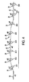
- FIGURE 4 is a view of a segment of the media path in a marking engine employing the method of the present disclosure
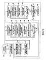
- FIGURE 5 is a block flow diagram of the control strategy of the present disclosure.
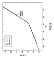
- FIGURE 6 is a graph of a estimated sheet position and actual sheet position as a function of time for the control of the present disclosure
- FIGURE 7 is a graphical presentation of a sheet position error as a function of time for a portion of the media path of FIGURE 1 ;
- FIGURE 8 is a graphical presentation of sheet position error as a function of progression through the media path of FIGURE 3 ;
- FIGURE 9 is a graphical presentation of the sheet position error as a function of distance progressed through the media path of FIGURE 3 for a print job using the control technique of the prior art.
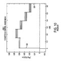
- FIGURE 10 is a graphical presentation similar to FIGURE 9 of another print job employing prior art control technique.
- an arrangement for a photocopier/printer is indicated generally at 10 includes a plurality of image marking engines 12, 14, 16, 18 arranged to receive media sheets from at least one feeder 20 and to output printed sheets to a finisher as indicated generally at 24.
- each of the marking engines includes various processing paths and inter-engine transport paths for accomplishing the desired marking on the print media sheets as for example, single or duplex printing, and thus may require sheet inverters as is known in the art of digital printing.
- Each of the marking engines 12, 14, 16, 18 have intermediate paths therein determined by a plurality of pairs of nip rollers 26 and sensors 28 located therealong for defining and monitoring the movement of sheet media along a given path determined by the controller for the print job as will hereinafter be described in greater detail.
- a media path controller indicated generally at 30, includes sheet controllers 32 and nip selector 34, nip controller 36, sheet reference trajectory generators 38, and sheet observer 40.
- the nip controllers provide a voltage signal, denoted u, to the nip roller motors along the paper path as indicated by reference numeral 42.
- the sensors provide nip velocity output signals denoted by the reference character "s" along line 44 and sheet present sensor signals denoted by "Sensors" along line 46 to the input of the trajectory generators 38 and the sheet observer 40.
- the sheet reference trajectory generators 38 also receive input instructions from the path planner controller 48 based upon user inputs (not shown) for the printing job.
- the sheet reference trajectory generators 38 provide an output along line 52 to the sheet controllers 32 of the reference sheet positions x d and an output along line 54 of the reference sheet velocities v d to the sheet controllers 32.
- the sheet reference trajectory generators 38 generate the desired sheet trajectories including the positions and velocities x d and v d for each sheet that enters the system using information from the planner 48.
- the reference trajectories are designed to provide desired velocity matching between the various locations in the media path such as for the on-ramp and highway locations wherein the on-ramp trajectories start at printer exit velocity and end at the highway velocity.
- the sheet observer 40 provides an output along line 56 to the sheet controllers 32 of the estimated sheet positions x hat .
- the sheet controllers 32 provide an input along line 58 of the desired sheet velocities v d,sheet to the nip selector 34 which provides an output along line 60 of the desired nip velocities s d to the nip controllers 36.
- the media or paper path 42 is illustrated for a module 43 comprising a module with individual pairs of nip rollers 126, 226, 326, 426, 526, 626, 726, 826, 926, 1026 shown along the path as are gates 27-1 and 27-2.
- the sensors 28 are disposed with each pair of nip rollers.
- each of the nip roller pairs 26 is driven by an individual drive motor 29 only one of which is shown in FIGURE 3 for the sake of clarity of illustration; however, it will be understood that an individual motor is provided for each of the nip roller pairs 26 and is connected to the nip controllers 36.
- Each of the nip roller pairs and gates has a sensor denoted respectively 128, 228, 328, 428, 528, 628, 728, 828, 928, 1028 disposed closely adjacent thereto for sensing media position and velocity of the adjacent nip station.
- the gates denoted 27-1 and 27-2 are solenoid operated for choosing the exit path for the media which enters the module or path segment at the upper left hand set of nip rollers 26 and exits at the lower set of nip rollers as determined by the choice of energization of solenoid 27-1 or solenoid 27-2.
- FIGURE 4 a portion of another media path 43 is shown with a plurality of media sheets denoted by reference numerals 58, 60, 62.
- each of the nip roller pairs 26-1 through 26-8 has one of the sensors 28 disposed adjacent thereto on the input side thereof to sense the arrival of the leading edge of the sheet at the respective pair of nip rollers.
- the sheet 62 as shown between the nip roller pairs 26-7 and 26-8 has a reference sheet velocity vd1 and the nip rollers have desired nip velocities sd7 and sd8.
- the sheet 60 passing through the nip roller pairs 26-2 through 26-6 has a reference sheet velocity vd2; and, the nip rollers have respectively desired nip velocities denoted sd1 through sd6.
- the sheet velocity of the sheet 58 entering the nips 26-1 has a reference sheet velocity denoted vd3 in FIGURE 4 .
- each of the pairs of nip rollers 26-1 through 26-8 is driven by an individual drive motor (such as motor 29 in FIGURE 3 ) which permits separate individual control of the surface velocities of each pair of nip rollers.
- nip rollers that touch a sheet are assigned that sheet's desired velocity; whereas nip rollers that are empty are assigned the incoming or upstream sheet's desired velocity.
- the assignment of the nip velocities for the empty nip rollers of the desired sheet velocity of the upstream or incoming sheet thus reduces the possibility of skewing, jamming or tearing of the sheet when entering each pair of nip rollers.
- step 70 the user print job requirements are inputted to the path planner 48 (see FIGURE 2 ) at step 72 and the controller 30 receives the instructions for the sheet path plan at step 74 and monitors the media path entry sensors and entry events for all sheets entering and exiting the media path.
- the controller proceeds at step 76 to read all the sheet sensors and the nip roller velocity sensors.
- step 78 to apply the algorithm of the present disclosure and perform the calculations for each sheet in the media path as follows.
- step 80 proceeds to step 80 and computes the estimated position x hat and the velocity v hat .
- the system proceeds to step 82 and computes the reference position x d and the velocity v d at step 84.
- the sheet observer 40 generates estimates of the positions and velocities x hat and v hat of all sheets in the media path using a model based estimator and utilizing all control signals such as motor voltages, motor current, step motor pulses, gate actuation signals, and all sensor signals including encoder, tachometer, and sheet sensor signals from optical or mechanical point sensors or array sensors.
- the sheet controllers 32 generate control signals for desired sheet velocities v d,sheet to insure that all the sheets stay on track and follow their respective reference trajectories. Control is determined as a function of the reference trajectories and the actual sheet positions and velocities as determined by the sheet observer 40.
- the system may utilize proportional control with velocity feed-forward for enhanced stability, zero-state tracking error and ease of tuning.
- step 86 the system proceeds to step 86 and computes the sheet position and velocity errors based upon the computations of steps 82 and 84.
- K p is a controller proportional gain constant
- x d is the current reference trajectory position
- x hat is the current estimated sheet position
- v d is the current reference trajectory velocity
- step 90 maps the desired sheet velocities v d,sheet to desired nip velocities s d for each nip roller pair in the selected media path.
- each nip controller 36 Utilizing the desired nip velocities from step 90, and the actual or estimated nip velocity from the nip motor sensors or step motor pulses, each nip controller 36 generates a nip motor control signal u which may include voltage, current or step motor pulses to insure that the nip velocity s tracks the desired nip velocity s d .
- step 92 The system then proceeds to step 92 and enquires as to whether all sheets present in the media path have been processed; and, if the answer is affirmative, the system proceeds to step 94 where, for each nip in the media path, proceeds to assign its desired velocity to be the upstream nip velocity if the nip is empty at step 96, for each gate in the media path, proceeds to generate an actuation voltage/step motor pulses to actuate the gate to the desired position in anticipation for the next sheet to reach it so that the sheet is diverted into the correct part of the media path.
- step 98 calculates the desired control signal for the actuator such as one of the nip motors 29 or one of the gate solenoids 27-1, 27-2 at step 100.
- step 92 recycles to step 82.
- step 102 The system then proceeds to step 102 and enquires as to whether all nips in the path have been processed; and, if the determination at step 102 is affirmative, the system proceeds to step 104 and enquires if there are sheets still in the path or more arriving into the path. If the determination at step 102 is negative, the system recycles to step 96.
- step 104 If the determination at step 104 is affirmative, the system recycles to step 74; however, if the determination at step 104 is negative, the print job is considered complete at step 106.
- FIGURES 6 and 1 measurements of the estimated sheet position x hat and the reference sheet position x d were taken for a sheet traversing the path in the on-ramp portion of an IME as indicated in FIGURE 1 .
- the data for both x hat and x d were plotted as a function of time and resultant plot is illustrated in FIGURE 6 wherein it is noted in which the values of x hat are plotted graphically in solid line and those of x d in dashed line. It is noted that where the sensors updated the control algorithm at about 14.85 seconds and about 15.22 seconds the actual subsequent position of the leading edge of the sheet was made to coincide with the desired reference trajectory position x d .
- the sheet tracking errors that is the difference between the reference position x d and the estimated position x hat have been plotted from the entry at sensor 128 of the module shown in FIGURE 3 to just slightly upstream of the sensor 628. It is to be noted that this sensor 628 is the second bend in the media path which induces additional disturbances on sheets. After this latter bend, the sheets exit the output module and all control actions terminate, thus no removal of these errors is possible.
- the media path traversed by the sheets includes one 90 degree bend and is approximately 0.6 meters long; and, the results of these trials have been summarized in Table 1 which shows the mean tracking errors and their range for the three print jobs run for comparison purposes.
- FIGURE 7 shows a plot of the tracking error as a function of time; and, the point in time wherein the control algorithm operates to begin removing the tracking error is noted as beginning at about 26.8 seconds.
- the media employed for Job 1 comprise standard 4024, 75 gsm paper; and, the media employed for Jobs 2 and 3 comprised a mix of 2 sheets of 60 gsm, 2 sheets of 75 gsm 4024, 2 sheets of 90 gsm, 2 sheets of 199 gsm glossy card stock, and 2 sheets of 216 gsm matte card stock. Jobs 1 and 2 were run with existing open loop control and Job 3 was printed employing the new control algorithm of the present disclosure.
- the tracking error x d - x hat is plotted as a function of path position and shows that initially, the tracking error was about 40 mm at sensor 128; whereas, by the time the sheet leading edge reached sensor 628, the tracking error has been reduced to less than 5 mm.
- the tracking error for Jobs 1 and 2 employing the existing open loop control show that for the same path movement, the tracking error happened to be reduced from the initial 40 mm to 20 mm, but could also have increased to 60 mm since there was no active control, only random disturbances acting on the sheets, thus, upon comparison with Table 1, illustrates the substantially greater reduction in tracking error for control of the nip drives by using the presently disclosed algorithm.
Landscapes
- Physics & Mathematics (AREA)
- General Physics & Mathematics (AREA)
- Delivering By Means Of Belts And Rollers (AREA)
- Paper Feeding For Electrophotography (AREA)
- Controlling Sheets Or Webs (AREA)
Abstract
Description
- The present disclosure relates to digital photocopying and printing on print media sheets and particularly such processes in which the media sheets are fed serially from at least one tray or feeder and may traverse any of several chosen paths through one or a multiplicity of marking engines. In such photocopying and printing, the media sheets typically pass through a myriad of nip rollers and gates where the transport speed may be varied and the sheets are directed around numerous bends and the sheets may also be inverted for duplex printing or printing on both sides of the media sheet.
- Heretofore, in digital photocopying/printing and particularly with electrostatic photocopiers, the media sheet path is chosen by the electronic programmer once the user has inputted the print job requirements. The sheets are fed and transported through the marking engine(s) with occasional or very limited sheet position readings by sensors located along the sheet path for providing a basis for correcting the timing of the media sheet feed into the marking engine(s) and the progress of the media sheets through the marking engine(s). The progression of media sheets through the marking engine(s) has thus essentially been accomplished by open loop control.
- Where media sheets progress through a complicated transport path of multiple nip rollers, bends, and gates, variations in the path length due to varying properties of the print sheet media such as varying length, variations in the velocity on the surface of the nip rollers, variations in the bends through which the sheet traverses have allowed sheet positioning errors to compound thereby resulting in collisions, mis-registrations and jamming. Problems of this sort have been particularly acute in arrangements where large documents are to be printed at high speed in parallel paths through multiple marking engines. The combination of high sheet velocity and extended complex sheet paths are intolerant of substantial variations in the timing of the sheet position along the path in order to prevent collisions, mis-registration and jamming.
- Thus, it has been desired to provide a way or means of improving the media sheet control and transport through marking engines in digital printing in a manner which eliminates or minimizes mis-registration and jamming.
- The present disclosure describes a method of controlling print sheet media traverse through complex or multiple paths in digital marking engines. The progression of the sheets through the path established by the electronic controller, for the particular user requested print job, provides for each of the nip rollers to be driven by individual variable speed motors; and, sheet position sensors are disposed at each of the bends and gates in the path to provide information to the controller upon the arrival of a sheet at that sensor station. The controller then applies a correction algorithm to generate a control signal for the motor drive of the proximate nip rollers to correct for any errors in the sheet position with respect to the planned program through the chosen media path in order to prevent mis-registration and jamming. Thus, the individual variable speed drive to each of the nip rollers enables the controller to correct for mis-positioning of the sheets irrespective of the location of the positioning error within the marking engine thereby providing essentially closed loop control within the system and particularly the media path.
-
FIGURE 1 is a pictorial schematic of a plurality of image marking engines illustrating a complex media path; -
FIGURE 2 is an overall block flow diagram of the control system of the present disclosure; -
FIGURE 3 is a pictorial representation of the portion of the sheet media path through a marking engine employing the control of the present disclosure; -
FIGURE 4 is a view of a segment of the media path in a marking engine employing the method of the present disclosure; -
FIGURE 5 is a block flow diagram of the control strategy of the present disclosure; -
FIGURE 6 is a graph of a estimated sheet position and actual sheet position as a function of time for the control of the present disclosure; -
FIGURE 7 is a graphical presentation of a sheet position error as a function of time for a portion of the media path ofFIGURE 1 ; -
FIGURE 8 is a graphical presentation of sheet position error as a function of progression through the media path ofFIGURE 3 ; -
FIGURE 9 is a graphical presentation of the sheet position error as a function of distance progressed through the media path ofFIGURE 3 for a print job using the control technique of the prior art; and -
FIGURE 10 is a graphical presentation similar toFIGURE 9 of another print job employing prior art control technique. - Referring to
FIGURE 1 , an arrangement for a photocopier/printer is indicated generally at 10 includes a plurality ofimage marking engines feeder 20 and to output printed sheets to a finisher as indicated generally at 24. It will be understood that each of the marking engines includes various processing paths and inter-engine transport paths for accomplishing the desired marking on the print media sheets as for example, single or duplex printing, and thus may require sheet inverters as is known in the art of digital printing. - Each of the
marking engines nip rollers 26 andsensors 28 located therealong for defining and monitoring the movement of sheet media along a given path determined by the controller for the print job as will hereinafter be described in greater detail. - Referring to
FIGURE 2 , a media path controller indicated generally at 30, includessheet controllers 32 andnip selector 34,nip controller 36, sheetreference trajectory generators 38, andsheet observer 40. The nip controllers provide a voltage signal, denoted u, to the nip roller motors along the paper path as indicated byreference numeral 42. The sensors provide nip velocity output signals denoted by the reference character "s" alongline 44 and sheet present sensor signals denoted by "Sensors" alongline 46 to the input of thetrajectory generators 38 and thesheet observer 40. The sheetreference trajectory generators 38 also receive input instructions from thepath planner controller 48 based upon user inputs (not shown) for the printing job. - The sheet
reference trajectory generators 38 provide an output alongline 52 to thesheet controllers 32 of the reference sheet positions xd and an output alongline 54 of the reference sheet velocities vd to thesheet controllers 32. - Referring to
FIGURE 2 , the sheetreference trajectory generators 38 generate the desired sheet trajectories including the positions and velocities xd and vd for each sheet that enters the system using information from theplanner 48. The reference trajectories are designed to provide desired velocity matching between the various locations in the media path such as for the on-ramp and highway locations wherein the on-ramp trajectories start at printer exit velocity and end at the highway velocity. - The
sheet observer 40 provides an output alongline 56 to thesheet controllers 32 of the estimated sheet positions xhat. Thesheet controllers 32 provide an input alongline 58 of the desired sheet velocities vd,sheet to thenip selector 34 which provides an output alongline 60 of the desired nip velocities sd to thenip controllers 36. - Referring to
FIGURES 3 and4 , the media orpaper path 42 is illustrated for amodule 43 comprising a module with individual pairs ofnip rollers sensors 28 are disposed with each pair of nip rollers. Referring toFIGURE 3 , each of thenip roller pairs 26 is driven by anindividual drive motor 29 only one of which is shown inFIGURE 3 for the sake of clarity of illustration; however, it will be understood that an individual motor is provided for each of thenip roller pairs 26 and is connected to thenip controllers 36. Each of the nip roller pairs and gates has a sensor denoted respectively 128, 228, 328, 428, 528, 628, 728, 828, 928, 1028 disposed closely adjacent thereto for sensing media position and velocity of the adjacent nip station. - Referring to
FIGURE 3 , the gates denoted 27-1 and 27-2 are solenoid operated for choosing the exit path for the media which enters the module or path segment at the upper left hand set ofnip rollers 26 and exits at the lower set of nip rollers as determined by the choice of energization of solenoid 27-1 or solenoid 27-2. - Referring to
FIGURE 4 , a portion ofanother media path 43 is shown with a plurality of media sheets denoted byreference numerals - With reference to
FIGURE 4 , each of the nip roller pairs 26-1 through 26-8 has one of thesensors 28 disposed adjacent thereto on the input side thereof to sense the arrival of the leading edge of the sheet at the respective pair of nip rollers. - Referring to
FIGURE 4 , thesheet 62 as shown between the nip roller pairs 26-7 and 26-8 has a reference sheet velocity vd1 and the nip rollers have desired nip velocities sd7 and sd8. Thesheet 60 passing through the nip roller pairs 26-2 through 26-6 has a reference sheet velocity vd2; and, the nip rollers have respectively desired nip velocities denoted sd1 through sd6. The sheet velocity of thesheet 58 entering the nips 26-1 has a reference sheet velocity denoted vd3 inFIGURE 4 . It will be understood that each of the pairs of nip rollers 26-1 through 26-8 is driven by an individual drive motor (such asmotor 29 inFIGURE 3 ) which permits separate individual control of the surface velocities of each pair of nip rollers. - In the media path shown in
FIGURE 4 , the nip rollers that touch a sheet are assigned that sheet's desired velocity; whereas nip rollers that are empty are assigned the incoming or upstream sheet's desired velocity. With reference toFIGURE 4 , the following applies:


- The assignment of the nip velocities for the empty nip rollers of the desired sheet velocity of the upstream or incoming sheet thus reduces the possibility of skewing, jamming or tearing of the sheet when entering each pair of nip rollers.
- Referring to
FIGURE 5 , the operation of thecontroller 30 is shown in block flow diagram wherein atstep 70 the user print job requirements are inputted to the path planner 48 (seeFIGURE 2 ) atstep 72 and thecontroller 30 receives the instructions for the sheet path plan atstep 74 and monitors the media path entry sensors and entry events for all sheets entering and exiting the media path. The controller proceeds atstep 76 to read all the sheet sensors and the nip roller velocity sensors. The system then proceeds tostep 78 to apply the algorithm of the present disclosure and perform the calculations for each sheet in the media path as follows. The system proceeds to step 80 and computes the estimated position xhat and the velocity vhat. Upon completion of the computations in step 80, the system proceeds tostep 82 and computes the reference position xd and the velocity vd atstep 84. - The
sheet observer 40 generates estimates of the positions and velocities xhat and vhat of all sheets in the media path using a model based estimator and utilizing all control signals such as motor voltages, motor current, step motor pulses, gate actuation signals, and all sensor signals including encoder, tachometer, and sheet sensor signals from optical or mechanical point sensors or array sensors. - The
sheet controllers 32 generate control signals for desired sheet velocities vd,sheet to insure that all the sheets stay on track and follow their respective reference trajectories. Control is determined as a function of the reference trajectories and the actual sheet positions and velocities as determined by thesheet observer 40. The system may utilize proportional control with velocity feed-forward for enhanced stability, zero-state tracking error and ease of tuning. - Referring to
FIGURE 5 , the system proceeds tostep 86 and computes the sheet position and velocity errors based upon the computations ofsteps - The system then proceeds to step 88 and computes the desired sheet velocity according to the algorithm

where Kp is a controller proportional gain constant, xd is the current reference trajectory position, xhat is the current estimated sheet position, and vd is the current reference trajectory velocity. - The system then proceeds to
step 90 and maps the desired sheet velocities vd,sheet to desired nip velocities sd for each nip roller pair in the selected media path. - Utilizing the desired nip velocities from
step 90, and the actual or estimated nip velocity from the nip motor sensors or step motor pulses, eachnip controller 36 generates a nip motor control signal u which may include voltage, current or step motor pulses to insure that the nip velocity s tracks the desired nip velocity sd. The system then proceeds tostep 92 and enquires as to whether all sheets present in the media path have been processed; and, if the answer is affirmative, the system proceeds tostep 94 where, for each nip in the media path, proceeds to assign its desired velocity to be the upstream nip velocity if the nip is empty atstep 96, for each gate in the media path, proceeds to generate an actuation voltage/step motor pulses to actuate the gate to the desired position in anticipation for the next sheet to reach it so that the sheet is diverted into the correct part of the media path. - The system then proceeds to
step 98 and calculates the desired control signal for the actuator such as one of thenip motors 29 or one of the gate solenoids 27-1, 27-2 atstep 100. - However, if the determination at
step 92 is negative, the system recycles to step 82. - The system then proceeds to step 102 and enquires as to whether all nips in the path have been processed; and, if the determination at
step 102 is affirmative, the system proceeds to step 104 and enquires if there are sheets still in the path or more arriving into the path. If the determination atstep 102 is negative, the system recycles to step 96. - If the determination at
step 104 is affirmative, the system recycles to step 74; however, if the determination atstep 104 is negative, the print job is considered complete atstep 106. - Referring to
FIGURES 6 and1 , measurements of the estimated sheet position xhat and the reference sheet position xd were taken for a sheet traversing the path in the on-ramp portion of an IME as indicated inFIGURE 1 . The data for both xhat and xd were plotted as a function of time and resultant plot is illustrated inFIGURE 6 wherein it is noted in which the values of xhat are plotted graphically in solid line and those of xd in dashed line. It is noted that where the sensors updated the control algorithm at about 14.85 seconds and about 15.22 seconds the actual subsequent position of the leading edge of the sheet was made to coincide with the desired reference trajectory position xd. - Referring to
FIGURES 3 and7 , the sheet tracking errors that is the difference between the reference position xd and the estimated position xhat have been plotted from the entry atsensor 128 of the module shown inFIGURE 3 to just slightly upstream of thesensor 628. It is to be noted that thissensor 628 is the second bend in the media path which induces additional disturbances on sheets. After this latter bend, the sheets exit the output module and all control actions terminate, thus no removal of these errors is possible. The media path traversed by the sheets includes one 90 degree bend and is approximately 0.6 meters long; and, the results of these trials have been summarized in Table 1 which shows the mean tracking errors and their range for the three print jobs run for comparison purposes. -
FIGURE 7 shows a plot of the tracking error as a function of time; and, the point in time wherein the control algorithm operates to begin removing the tracking error is noted as beginning at about 26.8 seconds. - Referring to Table 1, the data for the three print jobs performed for comparison purposes is given for the
sensor locations FIGURE 3 . The media employed forJob 1 comprise standard 4024, 75 gsm paper; and, the media employed forJobs gsm 4024, 2 sheets of 90 gsm, 2 sheets of 199 gsm glossy card stock, and 2 sheets of 216 gsm matte card stock.Jobs Job 3 was printed employing the new control algorithm of the present disclosure. - Referring to
FIGURE 8 , the tracking error xd - xhat is plotted as a function of path position and shows that initially, the tracking error was about 40 mm atsensor 128; whereas, by the time the sheet leading edge reachedsensor 628, the tracking error has been reduced to less than 5 mm. - Referring to
FIGURES 9 and10 , the tracking error forJobs TABLE I Experimental Data: 3 print jobs, 10 sheets each Job 1: Job 2: Job 3: 4024 media Mixed media Mixed media Open Loop Control Open Loop Control New control Update location Mean error Range Mean error Range Mean error Range [m] [mm] [mm] [mm] [mm] [mm] [mm] Entry 128+40 2.0 +40 2.0 +38 2.0 x = 0.005 228 +46 2.0 +46 4.0 +44 4.0 x = 0.151 (control starts here) 328 +37 2.0 +37 4.0 +23 2.0 x = 0.274 428 +28 2.0 +28 4.0 -1.0 0.0(*) x = 0.397 528 +19 2.0 +19 4.0 -10 0.0(*) x = 0.520 just upstream of 628 +19 2.0 +19 4.0 -2.8 0.2 x = 0.642 (control still removing error)
Claims (15)
- A method of controlling print media flow in digital printing comprising:(a) providing a digital print engine with a plurality of media sheet nip rollers defining at least one sheet path within the print engine;(b) disposing at least one print media sheet feeder proximate the print engine;(c) driving each of the nip rollers individually with a variable speed motor and propelling the print media through said at least one path;(d) sensing the position of each media sheet in the path and providing a sheet position signal indicative of the position of the sheet at a known time;(e) providing a controller responsive to the sheet position signal and effecting timed feeding of sheets from the feeder to the engine and determining a desired path and arrival times through selected ones of the nip rollers; and,(f) mapping the sensed media sheet positions and generating a speed control signal for each motor based upon the sensed media sheet position and driving the motor at a desired speed to position the sheet on the selected path at a desired position.
- A method of controlling print media flow in digital printing comprising:(a) providing a digital print engine with a plurality of media sheet nip rollers defining at least one sheet path within the print engine;(b) disposing a print media sheet feeder proximate the print engine;(c) driving each of the nip rollers individually with a variable speed motor and propelling the print media through the path;(d) disposing a sensor at stations proximate selected nip rollers and sensing sheet position at a known time;(e) providing a controller and effecting timed feeding of sheets from the feeder to the engine and determining desired path and arrival times through selected nip rollers for each of a plurality of sheets fed in the path;(f) mapping the sensed sheet positions and generating a speed control signal for each motor based upon the sensed position of each of the plurality of sheets and driving the respective motor to position the respective sheet on the selected path at a desired position and arrival time.
- The method defined in claim 2, wherein the step of disposing a sensor includes disposing a sensor before each split point in the path, before each merge point in the path and after each bend in the path.
- The method defined in any of the preceding claims, wherein the step of generating a speed control signal includes generating a desired nip velocity signal Sds according to Sds = Kp (xd - xh) + vd, where Sds is the desired nip surface velocity, xd is the current desired sheet position in the path, xhat is the estimated sheet position, Kp is a proportional gain of the controller, and vd is the velocity of the desired sheet position.
- The method defined in any of the preceding claims, wherein the step of a controlling each motor includes driving downstream nip rollers at the same speed as the next adjacent upstream nip rollers in the media sheet path, when a sheet is not in contact with the downstream nip rollers.
- The method defined in any of the preceding claims, wherein the step of generating a speed control signal includes generating pulses for a stepper motor or employing an encoder.
- The method defined in any of the preceding claims, wherein the step of providing a controller includes providing a sheet controller for determining the desired sheet path through the engine and a nip controller for controlling each of the motors.
- A system for controlling sheet media in a digital print engine comprising:(a) a media sheet feeder disposed proximate the print engine and operative for timed feeding of sheets thereto;(b) a plurality of nip rollers in the engine disposed at progressive stations for defining a sheet media path therethrough;(c) a print job controller operative to define a desired media sheet path through selected nip rollers;(d) a sensor disposed proximate selected nip roller stations operative to sense media sheet position and provide a signal indicative thereof;(e) a nip controller disposed to receive the signal from each of the sensors; and,(f) a plurality of variable speed motors each disposed to drive one of the nips independently,wherein the nip controller is operative in response to the sensor signal to map the sheet positions to drive the respective motor to provide a nip velocity sufficient to move a sensed media sheet to a desired position in the path.
- A system for controlling sheet media in a digital print engine comprising:(a) a media sheet feeder disposed proximate the print engine and operative for timed feeding of sheets thereto;(b) a plurality of nip rollers in the engine disposed at progressive stations for defining a sheet media path therethrough;(c) a print job controller operative to define a desired media sheet path through selected nip rollers;(d) a sensor disposed proximate each of a plurality of selected nip roller stations and operative to sense media sheet position and provide a signal indicative thereof;(e) a plurality of sheet controllers operative to receive the originals from the sensors; and,(f) a plurality of variable speed motors each disposed to drive one of the nips independently.
- The system defined in claim 8 or claim 9, wherein the nip controller is operative to provide a desired nip (sheet) velocity sds according to sds = Kp (xd - xhat) + vd, where Kp is the proportional gain of the controller, xd is the current reference path position, xhat is the current estimated sheet position and vd is the velocity of the desired sheet position.
- The system defined in any of claims 8 to 10, wherein the sensor is selected from one of optical and mechanical.
- The system defined in any of claims 8 to 11, wherein the nip controller is operative to control the position error of the media sheet within a predetermined band.
- The system defined in any of claims 8 to 12, wherein the digital print engine includes an endless media sheet transport belt.
- The system defined in any of claims 8 to 13, wherein the sensor disposed proximate selected nip stations includes a sensor disposed before each split point in the path, before each merge point in the path and after each bend in the path.
- The system defined in any of claims 8 to 14, wherein the sensor is operative to sense the surface velocity of the nip roller and provide a signal indicative thereof.
Applications Claiming Priority (1)
| Application Number | Priority Date | Filing Date | Title |
|---|---|---|---|
| US12/103,253 US20090257808A1 (en) | 2008-04-15 | 2008-04-15 | Closed loop sheet control in print media paths |
Publications (2)
| Publication Number | Publication Date |
|---|---|
| EP2110711A1 true EP2110711A1 (en) | 2009-10-21 |
| EP2110711B1 EP2110711B1 (en) | 2011-04-27 |
Family
ID=40974588
Family Applications (1)
| Application Number | Title | Priority Date | Filing Date |
|---|---|---|---|
| EP09153501A Ceased EP2110711B1 (en) | 2008-04-15 | 2009-02-24 | Closed loop sheet control in print media paths |
Country Status (4)
| Country | Link |
|---|---|
| US (1) | US20090257808A1 (en) |
| EP (1) | EP2110711B1 (en) |
| JP (1) | JP2009256103A (en) |
| DE (1) | DE602009001133D1 (en) |
Families Citing this family (4)
| Publication number | Priority date | Publication date | Assignee | Title |
|---|---|---|---|---|
| US8672321B2 (en) | 2011-02-10 | 2014-03-18 | Xerox Corporation | Media path re-phasing |
| EP3230076B1 (en) * | 2014-12-11 | 2019-09-11 | Hewlett-Packard Development Company, L.P. | A printer comprising a bend sensor |
| US11260681B2 (en) | 2017-02-07 | 2022-03-01 | Hewlett-Packard Development Company, L.P. | Print medium position detection |
| US11879918B2 (en) * | 2022-02-16 | 2024-01-23 | Stowe Woodward Licensco Llc | Methods, devices, and systems for nip calibration |
Citations (5)
| Publication number | Priority date | Publication date | Assignee | Title |
|---|---|---|---|---|
| US5482265A (en) * | 1991-12-09 | 1996-01-09 | Ricoh Company, Ltd. | Sheet feeder for an image forming apparatus |
| US5678159A (en) * | 1996-06-26 | 1997-10-14 | Xerox Corporation | Sheet registration and deskewing device |
| US20050074267A1 (en) * | 2003-10-06 | 2005-04-07 | Xerox Corporation | Method and apparatus for controlling the velocity of copy substrates during registration |
| US20060039728A1 (en) * | 2004-08-23 | 2006-02-23 | Xerox Corporation | Printing system with inverter disposed for media velocity buffering and registration |
| US20060214359A1 (en) * | 2005-03-25 | 2006-09-28 | Xerox Corporation | Inverter with return/bypass paper path |
Family Cites Families (11)
| Publication number | Priority date | Publication date | Assignee | Title |
|---|---|---|---|---|
| US39728A (en) * | 1863-09-01 | Improvement in pumps | ||
| US74267A (en) * | 1868-02-11 | alley | ||
| US214359A (en) * | 1879-04-15 | Improvement in medicated candies | ||
| US4451027A (en) * | 1980-01-09 | 1984-05-29 | Burroughs Corp. | Constant spacing document feeder |
| US5337135A (en) * | 1993-09-30 | 1994-08-09 | Xerox Corporation | Higher productivity trayless duplex printer with variable path velocity |
| US5999758A (en) * | 1998-03-02 | 1999-12-07 | Xerox Corporation | Hybrid hierarchical control architecture for media handling |
| US6322069B1 (en) * | 1999-03-12 | 2001-11-27 | Xerox Corporation | Interpaper spacing control in a media handling system |
| US6374075B1 (en) * | 2000-04-28 | 2002-04-16 | Xerox Corporation | Printing systems and methods |
| US6973286B2 (en) * | 2004-01-21 | 2005-12-06 | Xerox Corporation | High print rate merging and finishing system for parallel printing |
| US7188929B2 (en) * | 2004-08-13 | 2007-03-13 | Xerox Corporation | Parallel printing architecture with containerized image marking engines |
| US7024152B2 (en) * | 2004-08-23 | 2006-04-04 | Xerox Corporation | Printing system with horizontal highway and single pass duplex |
-
2008
- 2008-04-15 US US12/103,253 patent/US20090257808A1/en not_active Abandoned
-
2009
- 2009-02-24 EP EP09153501A patent/EP2110711B1/en not_active Ceased
- 2009-02-24 DE DE602009001133T patent/DE602009001133D1/en active Active
- 2009-04-14 JP JP2009097812A patent/JP2009256103A/en not_active Withdrawn
Patent Citations (5)
| Publication number | Priority date | Publication date | Assignee | Title |
|---|---|---|---|---|
| US5482265A (en) * | 1991-12-09 | 1996-01-09 | Ricoh Company, Ltd. | Sheet feeder for an image forming apparatus |
| US5678159A (en) * | 1996-06-26 | 1997-10-14 | Xerox Corporation | Sheet registration and deskewing device |
| US20050074267A1 (en) * | 2003-10-06 | 2005-04-07 | Xerox Corporation | Method and apparatus for controlling the velocity of copy substrates during registration |
| US20060039728A1 (en) * | 2004-08-23 | 2006-02-23 | Xerox Corporation | Printing system with inverter disposed for media velocity buffering and registration |
| US20060214359A1 (en) * | 2005-03-25 | 2006-09-28 | Xerox Corporation | Inverter with return/bypass paper path |
Also Published As
| Publication number | Publication date |
|---|---|
| JP2009256103A (en) | 2009-11-05 |
| DE602009001133D1 (en) | 2011-06-09 |
| EP2110711B1 (en) | 2011-04-27 |
| US20090257808A1 (en) | 2009-10-15 |
Similar Documents
| Publication | Publication Date | Title |
|---|---|---|
| US6519443B1 (en) | Method for calculating a print medium pick time for an imaging apparatus that transports print media at variable speeds | |
| US20040223797A1 (en) | Method and apparatus for image forming capable of performing fast and stable sheet transfer operations | |
| US8256767B2 (en) | Sheet registration using edge sensors | |
| US9579814B2 (en) | Motor control system and method for a rotary hole punch system | |
| JP5511497B2 (en) | Sheet conveying apparatus and image forming apparatus | |
| JPH11255382A (en) | Method and device for aligning sheet and deskewing and its electrophotographic printing device | |
| JP2011088736A (en) | Sheet processing device system | |
| EP2110711B1 (en) | Closed loop sheet control in print media paths | |
| US8366102B2 (en) | Accurate sheet leading edge registration | |
| US8695973B2 (en) | Sheet registration for a printmaking device using trail edge sensors | |
| US20080018923A1 (en) | Image recording apparatus and image recording method for the image recording apparatus image | |
| EP2278409A2 (en) | Extended registration control of a sheet in a media handling assembly | |
| JP4229022B2 (en) | Conveyance control device, conveyance system, and image forming system | |
| US6327458B1 (en) | Method and apparatus for positioning paper in an imaging system having an intermediate transfer medium | |
| US8336986B2 (en) | Image forming apparatus, image forming method and computer readable storage medium | |
| JP2000062997A (en) | Shifting control copy sheet | |
| JP4796905B2 (en) | Punch unit, paper post-processing apparatus including the punch unit, and punching method | |
| US8672321B2 (en) | Media path re-phasing | |
| CN101130316B (en) | Recording device and method for controlling the recording device | |
| US20090162119A1 (en) | Method for image to paper (iop) registration: image one to image two error compensation | |
| Cloet et al. | Intersheet spacing control and controllability of a copier paper path | |
| JP2006082936A (en) | Paper punching device, paper processing device, and image forming device | |
| JP2006347714A (en) | Mark position detection device, paper cutting device, and paper folding mold forming device | |
| US6499733B1 (en) | Method and apparatus for feeding sheet material into a printer or copier | |
| JPH06156797A (en) | Paper transport device of image forming device |
Legal Events
| Date | Code | Title | Description |
|---|---|---|---|
| PUAI | Public reference made under article 153(3) epc to a published international application that has entered the european phase |
Free format text: ORIGINAL CODE: 0009012 |
|
| AK | Designated contracting states |
Kind code of ref document: A1 Designated state(s): AT BE BG CH CY CZ DE DK EE ES FI FR GB GR HR HU IE IS IT LI LT LU LV MC MK MT NL NO PL PT RO SE SI SK TR |
|
| AX | Request for extension of the european patent |
Extension state: AL BA RS |
|
| 17P | Request for examination filed |
Effective date: 20100421 |
|
| 17Q | First examination report despatched |
Effective date: 20100528 |
|
| AKX | Designation fees paid |
Designated state(s): DE FR GB |
|
| GRAJ | Information related to disapproval of communication of intention to grant by the applicant or resumption of examination proceedings by the epo deleted |
Free format text: ORIGINAL CODE: EPIDOSDIGR1 |
|
| GRAP | Despatch of communication of intention to grant a patent |
Free format text: ORIGINAL CODE: EPIDOSNIGR1 |
|
| GRAP | Despatch of communication of intention to grant a patent |
Free format text: ORIGINAL CODE: EPIDOSNIGR1 |
|
| GRAS | Grant fee paid |
Free format text: ORIGINAL CODE: EPIDOSNIGR3 |
|
| GRAA | (expected) grant |
Free format text: ORIGINAL CODE: 0009210 |
|
| AK | Designated contracting states |
Kind code of ref document: B1 Designated state(s): DE FR GB |
|
| REG | Reference to a national code |
Ref country code: GB Ref legal event code: FG4D |
|
| REF | Corresponds to: |
Ref document number: 602009001133 Country of ref document: DE Date of ref document: 20110609 Kind code of ref document: P |
|
| REG | Reference to a national code |
Ref country code: DE Ref legal event code: R096 Ref document number: 602009001133 Country of ref document: DE Effective date: 20110609 |
|
| PLBE | No opposition filed within time limit |
Free format text: ORIGINAL CODE: 0009261 |
|
| STAA | Information on the status of an ep patent application or granted ep patent |
Free format text: STATUS: NO OPPOSITION FILED WITHIN TIME LIMIT |
|
| 26N | No opposition filed |
Effective date: 20120130 |
|
| REG | Reference to a national code |
Ref country code: DE Ref legal event code: R097 Ref document number: 602009001133 Country of ref document: DE Effective date: 20120130 |
|
| REG | Reference to a national code |
Ref country code: FR Ref legal event code: PLFP Year of fee payment: 8 |
|
| REG | Reference to a national code |
Ref country code: FR Ref legal event code: PLFP Year of fee payment: 9 |
|
| REG | Reference to a national code |
Ref country code: FR Ref legal event code: PLFP Year of fee payment: 10 |
|
| PGFP | Annual fee paid to national office [announced via postgrant information from national office to epo] |
Ref country code: DE Payment date: 20180122 Year of fee payment: 10 Ref country code: GB Payment date: 20180122 Year of fee payment: 10 |
|
| PGFP | Annual fee paid to national office [announced via postgrant information from national office to epo] |
Ref country code: FR Payment date: 20180123 Year of fee payment: 10 |
|
| REG | Reference to a national code |
Ref country code: DE Ref legal event code: R119 Ref document number: 602009001133 Country of ref document: DE |
|
| GBPC | Gb: european patent ceased through non-payment of renewal fee |
Effective date: 20190224 |
|
| PG25 | Lapsed in a contracting state [announced via postgrant information from national office to epo] |
Ref country code: GB Free format text: LAPSE BECAUSE OF NON-PAYMENT OF DUE FEES Effective date: 20190224 Ref country code: DE Free format text: LAPSE BECAUSE OF NON-PAYMENT OF DUE FEES Effective date: 20190903 |
|
| PG25 | Lapsed in a contracting state [announced via postgrant information from national office to epo] |
Ref country code: FR Free format text: LAPSE BECAUSE OF NON-PAYMENT OF DUE FEES Effective date: 20190228 |