EP2110512A1 - Turbine blade twist angle correction tooling - Google Patents
Turbine blade twist angle correction tooling Download PDFInfo
- Publication number
- EP2110512A1 EP2110512A1 EP09250376A EP09250376A EP2110512A1 EP 2110512 A1 EP2110512 A1 EP 2110512A1 EP 09250376 A EP09250376 A EP 09250376A EP 09250376 A EP09250376 A EP 09250376A EP 2110512 A1 EP2110512 A1 EP 2110512A1
- Authority
- EP
- European Patent Office
- Prior art keywords
- blade
- twist angle
- engage
- adaptor
- socket drive
- Prior art date
- Legal status (The legal status is an assumption and is not a legal conclusion. Google has not performed a legal analysis and makes no representation as to the accuracy of the status listed.)
- Granted
Links
- 230000008439 repair process Effects 0.000 claims description 12
- 238000006073 displacement reaction Methods 0.000 claims description 4
- 239000007789 gas Substances 0.000 description 7
- 239000000523 sample Substances 0.000 description 7
- 238000000034 method Methods 0.000 description 5
- 230000001351 cycling effect Effects 0.000 description 2
- 230000007423 decrease Effects 0.000 description 2
- 239000000446 fuel Substances 0.000 description 2
- 230000000930 thermomechanical effect Effects 0.000 description 2
- 238000002485 combustion reaction Methods 0.000 description 1
- 239000000284 extract Substances 0.000 description 1
- 239000000203 mixture Substances 0.000 description 1
Images

Classifications
-
- F—MECHANICAL ENGINEERING; LIGHTING; HEATING; WEAPONS; BLASTING
- F01—MACHINES OR ENGINES IN GENERAL; ENGINE PLANTS IN GENERAL; STEAM ENGINES
- F01D—NON-POSITIVE DISPLACEMENT MACHINES OR ENGINES, e.g. STEAM TURBINES
- F01D5/00—Blades; Blade-carrying members; Heating, heat-insulating, cooling or antivibration means on the blades or the members
- F01D5/005—Repairing methods or devices
-
- B—PERFORMING OPERATIONS; TRANSPORTING
- B23—MACHINE TOOLS; METAL-WORKING NOT OTHERWISE PROVIDED FOR
- B23P—METAL-WORKING NOT OTHERWISE PROVIDED FOR; COMBINED OPERATIONS; UNIVERSAL MACHINE TOOLS
- B23P6/00—Restoring or reconditioning objects
- B23P6/002—Repairing turbine components, e.g. moving or stationary blades, rotors
-
- Y—GENERAL TAGGING OF NEW TECHNOLOGICAL DEVELOPMENTS; GENERAL TAGGING OF CROSS-SECTIONAL TECHNOLOGIES SPANNING OVER SEVERAL SECTIONS OF THE IPC; TECHNICAL SUBJECTS COVERED BY FORMER USPC CROSS-REFERENCE ART COLLECTIONS [XRACs] AND DIGESTS
- Y02—TECHNOLOGIES OR APPLICATIONS FOR MITIGATION OR ADAPTATION AGAINST CLIMATE CHANGE
- Y02T—CLIMATE CHANGE MITIGATION TECHNOLOGIES RELATED TO TRANSPORTATION
- Y02T50/00—Aeronautics or air transport
- Y02T50/60—Efficient propulsion technologies, e.g. for aircraft
-
- Y—GENERAL TAGGING OF NEW TECHNOLOGICAL DEVELOPMENTS; GENERAL TAGGING OF CROSS-SECTIONAL TECHNOLOGIES SPANNING OVER SEVERAL SECTIONS OF THE IPC; TECHNICAL SUBJECTS COVERED BY FORMER USPC CROSS-REFERENCE ART COLLECTIONS [XRACs] AND DIGESTS
- Y10—TECHNICAL SUBJECTS COVERED BY FORMER USPC
- Y10T—TECHNICAL SUBJECTS COVERED BY FORMER US CLASSIFICATION
- Y10T29/00—Metal working
- Y10T29/53—Means to assemble or disassemble
- Y10T29/53704—Means to assemble or disassemble tool chuck and tool
-
- Y—GENERAL TAGGING OF NEW TECHNOLOGICAL DEVELOPMENTS; GENERAL TAGGING OF CROSS-SECTIONAL TECHNOLOGIES SPANNING OVER SEVERAL SECTIONS OF THE IPC; TECHNICAL SUBJECTS COVERED BY FORMER USPC CROSS-REFERENCE ART COLLECTIONS [XRACs] AND DIGESTS
- Y10—TECHNICAL SUBJECTS COVERED BY FORMER USPC
- Y10T—TECHNICAL SUBJECTS COVERED BY FORMER US CLASSIFICATION
- Y10T29/00—Metal working
- Y10T29/53—Means to assemble or disassemble
- Y10T29/53796—Puller or pusher means, contained force multiplying operator
-
- Y—GENERAL TAGGING OF NEW TECHNOLOGICAL DEVELOPMENTS; GENERAL TAGGING OF CROSS-SECTIONAL TECHNOLOGIES SPANNING OVER SEVERAL SECTIONS OF THE IPC; TECHNICAL SUBJECTS COVERED BY FORMER USPC CROSS-REFERENCE ART COLLECTIONS [XRACs] AND DIGESTS
- Y10—TECHNICAL SUBJECTS COVERED BY FORMER USPC
- Y10T—TECHNICAL SUBJECTS COVERED BY FORMER US CLASSIFICATION
- Y10T29/00—Metal working
- Y10T29/53—Means to assemble or disassemble
- Y10T29/53796—Puller or pusher means, contained force multiplying operator
- Y10T29/53848—Puller or pusher means, contained force multiplying operator having screw operator
- Y10T29/53857—Central screw, work-engagers around screw
- Y10T29/53861—Work-engager arms along or parallel to screw
- Y10T29/5387—Pivotal arms
-
- Y—GENERAL TAGGING OF NEW TECHNOLOGICAL DEVELOPMENTS; GENERAL TAGGING OF CROSS-SECTIONAL TECHNOLOGIES SPANNING OVER SEVERAL SECTIONS OF THE IPC; TECHNICAL SUBJECTS COVERED BY FORMER USPC CROSS-REFERENCE ART COLLECTIONS [XRACs] AND DIGESTS
- Y10—TECHNICAL SUBJECTS COVERED BY FORMER USPC
- Y10T—TECHNICAL SUBJECTS COVERED BY FORMER US CLASSIFICATION
- Y10T29/00—Metal working
- Y10T29/53—Means to assemble or disassemble
- Y10T29/53961—Means to assemble or disassemble with work-holder for assembly
-
- Y—GENERAL TAGGING OF NEW TECHNOLOGICAL DEVELOPMENTS; GENERAL TAGGING OF CROSS-SECTIONAL TECHNOLOGIES SPANNING OVER SEVERAL SECTIONS OF THE IPC; TECHNICAL SUBJECTS COVERED BY FORMER USPC CROSS-REFERENCE ART COLLECTIONS [XRACs] AND DIGESTS
- Y10—TECHNICAL SUBJECTS COVERED BY FORMER USPC
- Y10T—TECHNICAL SUBJECTS COVERED BY FORMER US CLASSIFICATION
- Y10T29/00—Metal working
- Y10T29/53—Means to assemble or disassemble
- Y10T29/53978—Means to assemble or disassemble including means to relatively position plural work parts
-
- Y—GENERAL TAGGING OF NEW TECHNOLOGICAL DEVELOPMENTS; GENERAL TAGGING OF CROSS-SECTIONAL TECHNOLOGIES SPANNING OVER SEVERAL SECTIONS OF THE IPC; TECHNICAL SUBJECTS COVERED BY FORMER USPC CROSS-REFERENCE ART COLLECTIONS [XRACs] AND DIGESTS
- Y10—TECHNICAL SUBJECTS COVERED BY FORMER USPC
- Y10T—TECHNICAL SUBJECTS COVERED BY FORMER US CLASSIFICATION
- Y10T29/00—Metal working
- Y10T29/53—Means to assemble or disassemble
- Y10T29/53996—Means to assemble or disassemble by deforming
Definitions
- the present invention relates to turbine blade repair procedures and tooling.
- the present invention relates to turbine blade twist angle correction tooling.
- a gas turbine engine commonly includes a fan, a compressor, a combustor, a turbine, and an exhaust nozzle.
- working medium gases for example air
- the compressed air is channeled to the combustor where fuel is added to the air and the air/fuel mixture is ignited.
- the products of combustion are discharged to the turbine section, which extracts work from these products to produce useful thrust to power, for example, an aircraft in flight.
- the compressor and turbine commonly include alternating stages of rotor blades and stator vanes.
- Compressor and turbine blades and vanes often include complex, contoured airfoil geometries designed to optimally interact with the working medium gas passing through the engine.
- One common feature of airfoil geometries is the blade twist angle.
- the twist angle is the angular displacement of the airfoil about a spanwise axis, such as the stacking axis, from the root to the tip of the airfoil.
- the blade twist angle feature which is a critical characteristic of gas turbine engine blades, decreases due to thermo-mechanical cycling and aerodynamic loading of the blades. The twist angle must be restored to the original manufactured condition during engine overhaul prior to returning the blade to service.
- Turbine blade twist correction is commonly accomplished by clamping the blade root in a fixture and manually applying a load to the tip of the blade using, for example a wrench configured to clamp the blade tip. An operator twists the blade using the wrench, measures the blade twist angle, and repeats the twisting procedure until the correct twist angle is reached. Because the operator can only estimate how much force to apply each time, this approach often requires many iterations to achieve the desired twist angle. This results in a time-consuming, labor-intensive, and costly process. This approach can also result in over-twist due to applying excessive force.
- the present invention includes a wrench for correcting the twist angle of a turbine blade, which wrench includes an adaptor configured to engage a tip of the blade, a socket drive configured to engage the adaptor, a first handle connected to a first side of the socket drive, a second handle connected to a second side of the socket drive, and a torque gauge configured to measure a load applied to the blade.
- Embodiments of the present invention also include a repair apparatus for correcting the twist angle of a turbine blade, which apparatus includes a base plate, a fixture connected to the base plate and configured to engage the root of the blade, a twist angle gauge connected to the base plate and configured to measure the twist angle of the blade, and a wrench configured to apply a measured load to a tip of the blade.
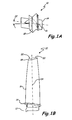
- FIGS. 1A and 1B are top and side views respectively of a twisted gas turbine blade.
- FIG. 2 is a perspective view of a repair apparatus for correcting the twist angle of the turbine blade shown in FIG. 1 .
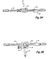
- FIGS. 3A and 3B are top and front views respectively of the wrench shown in FIG. 2 .
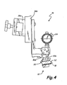
- FIG. 4 is a top view of the twist angle gauge shown in FIG. 2 .
- FIGS. 1A and 1B are top and side views respectively of twisted gas turbine blade 10, which includes root 12, platform 14, airfoil 16, shroud 18, and knife edges 20.
- blade 10 is a gas turbine blade including a twisted airfoil 16 which may be corrected using apparatuses according to the present invention.
- Blade 10 may be, for example, a shrouded high pressure turbine blade.
- Blade 10 includes root 12, which may include a dovetail or fir tree root 12 configured to be received in a slot in the rim of a rotor disc.
- Blade 10 also includes platform 14 integral with and radially outward of root 12. Airfoil 16 of blade 10 extends radially from platform 14 to shroud 18.
- Shroud 18 includes knife edges 20 designed to engage, for example, a stationary honeycomb seal arranged radially outward of turbine blade 10 mounted in the rim of the rotor disc.
- twist angle 22 of blade 10 is equal to the angular displacement of airfoil 16 about a spanwise axis, such as stacking axis 24 of airfoil 16, between platform 14 and shroud 18.
- twist angle 22 is represented by the angle between the blade root center plane and a line perpendicular to knife edge 20.
- twist angle 22 of blade 10 may decrease due to thermo-mechanical cycling and aerodynamic loading on blade 10. In order to extend the useful life of blade 10, twist angle 22 may be restored to the original manufactured condition during engine overhaul prior to returning blade 10 to service.
- FIG. 2 is a perspective view of repair apparatus 30 according to the present invention for correcting twist angle 22 of blade 10, which apparatus 30 includes base plate 32, fixture 34, twist angle gauge 36, and wrench 38.
- Base plate 32 may be configured to mount to a table or bench.
- toggle clamps may be mounted to the work bench and arranged to clamp the corners of base plate 32.
- Fixture 34 is connected to base plate 32 and configured to engage root 12 of blade 10.
- Fixture 34 may include, for example, blocks 34a, 34b and toggle clamp 34c. As shown in FIG. 2 , blocks 34a, 34b may be configured to engage two sides of root 12 of blade 10 as toggle clamp 34c is engaged.
- Blocks 34a, 34b of fixture 34 may be adapted to engage varying root geometries, such as a fir tree root geometry (see FIG. 3B ).
- Twist angle gauge 36 is connected to base plate 32 and configured to measure twist angle 22 of blade 10.
- Twist angle gauge 36 may be adjustably connected to, for example, gauge stand 36a and slide 36b.
- Gauge stand 36a may be configured to adjustably position gauge 36 vertically with respect to base plate 32 and slide 36b may be configured to move gauge 36 laterally into and out of engagement with blade 10.
- slide 36b, and thereby gauge 36 is positioned away from, or, out of engagement with blade 10.
- Slide 36b may be moved toward blade 10 to cause twist angle gauge 36 to engage, for example, one or more portions of blade 10, such as contacting shroud 18 of blade 10 to measure twist angle 22.
- Wrench 38 is configured to engage shroud 18 of blade 10 and to apply a measured load to blade 10 to correct twist angle 22.
- wrench 38 is exploded away from shroud 18 of blade 10 in FIG. 2 .
- the repair apparatus 30 shown in FIG. 2 may be used to correct twist angle 22 of blade 10.
- root 12 of blade 10 may be clamped in fixture 34 connected to base plate 32.
- Twist angle gauge 36 may be moved into position to measure an initial twist angle of blade 10 by contacting shroud 18. Twist angle gauge 36 may then be disengaged from blade 10 and wrench 38 may be clamped to shroud 18 of blade 10. A measured load may be applied to wrench 38 to re-twist blade 10 to a corrected twist angle.
- FIGS. 3A and 3B are top and front views respectively of wrench 38 engaging blade 10.
- Wrench 38 includes adaptor 40, socket drive 42, first handle 44, second handle 46, and torque gauge 48.
- First and second handles 44, 46 are connected to either side of socket drive 42.
- Socket drive 42 engages adaptor 40, which adapter 40 is configured to engage blade 10.
- Adaptor 40 may be configured in alternative embodiments of the present invention to engage turbine blades with varying tip configurations, such as shrouded and unshrouded blades and blades having squealer tips.
- adapter 40 engages shroud 18 of blade 10 by, for example, nesting shroud 18 into a pocket in adapter 40.
- Torque gauge 48 may be, for example, an electronic or electro-mechanical gauge configured to measure the load applied to blade 10 by wrench 38 during twist correction operations. Torque gauge 48 may be mounted to first handle 44 and may include an analog or electronic indicator configured to display the load applied to blade 10, thereby guarding against inadvertent over-twisting of blade 10. The tool might comprise only a single handle.
- FIG. 4 is a top view of twist angle gauge 36 positioned to engage blade 10, which gauge 36 includes jaws 50 having two probes 50a, 50b configured to contact shroud 18 of blade 10 at two points.
- gauge 36 is shown slightly out of engagement with shroud 18 of blade 10.
- Twist angle gauge 36 may be configured to extrapolate twist angle 22 of blade 10 by measuring the relative displacement of jaws 50 at probes 50a, 50b.
- gauge 36 may be moved into position to engage shroud 18 of blade 10 by, for example, moving gauge 36 laterally via slide 36b.
- Probes 50a, 50b of jaws 50 may be configured, for example, to engage the forward face of the aft knife edge 52 of blade 10.
- probe 50a may be configured to be pushed by knife edge face 52 until probe 50b touches knife edge face 52.
- Gauge 36 extrapolates twist angle 22 of blade 10 from the deflection of probe 50a relative to probe 50b. Twist angle 22 of blade 10 may be displayed on dial 54 of gauge 36.
- Embodiments of the present invention provide an apparatus including a twist angle correction wrench configured to apply a measured load to correct the twist angle of turbine blades.
- Providing operators a device that indicates the load delivered to the blade under repair reduces the number of iterations, if any, necessary to repair the blade twist angle, and substantially reduces the risk of blade over-twisting due to applying excessive force.
- Turbine blade repairs employing embodiments of the present invention therefore reduce repair time and cost, and simultaneously improve repair quality.
Landscapes
- Engineering & Computer Science (AREA)
- Mechanical Engineering (AREA)
- General Engineering & Computer Science (AREA)
- Structures Of Non-Positive Displacement Pumps (AREA)
Abstract
Description
- The present invention relates to turbine blade repair procedures and tooling. In particular, the present invention relates to turbine blade twist angle correction tooling.
- A gas turbine engine commonly includes a fan, a compressor, a combustor, a turbine, and an exhaust nozzle. During engine operation, working medium gases, for example air, are drawn into and compressed in the compressor. The compressed air is channeled to the combustor where fuel is added to the air and the air/fuel mixture is ignited. The products of combustion are discharged to the turbine section, which extracts work from these products to produce useful thrust to power, for example, an aircraft in flight.
- The compressor and turbine commonly include alternating stages of rotor blades and stator vanes. Compressor and turbine blades and vanes often include complex, contoured airfoil geometries designed to optimally interact with the working medium gas passing through the engine. One common feature of airfoil geometries is the blade twist angle. The twist angle is the angular displacement of the airfoil about a spanwise axis, such as the stacking axis, from the root to the tip of the airfoil. During normal engine operation, the blade twist angle feature, which is a critical characteristic of gas turbine engine blades, decreases due to thermo-mechanical cycling and aerodynamic loading of the blades. The twist angle must be restored to the original manufactured condition during engine overhaul prior to returning the blade to service.
- Turbine blade twist correction is commonly accomplished by clamping the blade root in a fixture and manually applying a load to the tip of the blade using, for example a wrench configured to clamp the blade tip. An operator twists the blade using the wrench, measures the blade twist angle, and repeats the twisting procedure until the correct twist angle is reached. Because the operator can only estimate how much force to apply each time, this approach often requires many iterations to achieve the desired twist angle. This results in a time-consuming, labor-intensive, and costly process. This approach can also result in over-twist due to applying excessive force.
- Therefore, improved tools and methods for correcting blade twist angle are needed.
- The present invention includes a wrench for correcting the twist angle of a turbine blade, which wrench includes an adaptor configured to engage a tip of the blade, a socket drive configured to engage the adaptor, a first handle connected to a first side of the socket drive, a second handle connected to a second side of the socket drive, and a torque gauge configured to measure a load applied to the blade.
- Embodiments of the present invention also include a repair apparatus for correcting the twist angle of a turbine blade, which apparatus includes a base plate, a fixture connected to the base plate and configured to engage the root of the blade, a twist angle gauge connected to the base plate and configured to measure the twist angle of the blade, and a wrench configured to apply a measured load to a tip of the blade.
-
FIGS. 1A and 1B are top and side views respectively of a twisted gas turbine blade. -
FIG. 2 is a perspective view of a repair apparatus for correcting the twist angle of the turbine blade shown inFIG. 1 . -
FIGS. 3A and 3B are top and front views respectively of the wrench shown inFIG. 2 . -
FIG. 4 is a top view of the twist angle gauge shown inFIG. 2 . -
FIGS. 1A and 1B are top and side views respectively of twistedgas turbine blade 10, which includesroot 12,platform 14,airfoil 16,shroud 18, andknife edges 20. InFIGS. 1A and 1B ,blade 10 is a gas turbine blade including atwisted airfoil 16 which may be corrected using apparatuses according to the present invention.Blade 10 may be, for example, a shrouded high pressure turbine blade. Blade 10 includesroot 12, which may include a dovetail orfir tree root 12 configured to be received in a slot in the rim of a rotor disc. Blade 10 also includesplatform 14 integral with and radially outward ofroot 12.Airfoil 16 ofblade 10 extends radially fromplatform 14 toshroud 18. Shroud 18 includesknife edges 20 designed to engage, for example, a stationary honeycomb seal arranged radially outward ofturbine blade 10 mounted in the rim of the rotor disc. In general,twist angle 22 ofblade 10 is equal to the angular displacement ofairfoil 16 about a spanwise axis, such asstacking axis 24 ofairfoil 16, betweenplatform 14 andshroud 18. For example, inFIG. 1A ,twist angle 22 is represented by the angle between the blade root center plane and a line perpendicular toknife edge 20. During normal engine operation,twist angle 22 ofblade 10 may decrease due to thermo-mechanical cycling and aerodynamic loading onblade 10. In order to extend the useful life ofblade 10,twist angle 22 may be restored to the original manufactured condition during engine overhaul prior to returningblade 10 to service. -
FIG. 2 is a perspective view ofrepair apparatus 30 according to the present invention for correctingtwist angle 22 ofblade 10, whichapparatus 30 includes base plate 32,fixture 34,twist angle gauge 36, andwrench 38. Base plate 32 may be configured to mount to a table or bench. For example, toggle clamps may be mounted to the work bench and arranged to clamp the corners of base plate 32. Fixture 34 is connected to base plate 32 and configured to engageroot 12 ofblade 10. Fixture 34 may include, for example,blocks toggle clamp 34c. As shown inFIG. 2 ,blocks root 12 ofblade 10 astoggle clamp 34c is engaged.Blocks fixture 34 may be adapted to engage varying root geometries, such as a fir tree root geometry (seeFIG. 3B ).Twist angle gauge 36 is connected to base plate 32 and configured to measuretwist angle 22 ofblade 10.Twist angle gauge 36 may be adjustably connected to, for example,gauge stand 36a andslide 36b. Gaugestand 36a may be configured to adjustably positiongauge 36 vertically with respect to base plate 32 andslide 36b may be configured to movegauge 36 laterally into and out of engagement withblade 10. For example, inFIG. 2 ,slide 36b, and thereby gauge 36, is positioned away from, or, out of engagement withblade 10.Slide 36b may be moved towardblade 10 to causetwist angle gauge 36 to engage, for example, one or more portions ofblade 10, such as contactingshroud 18 ofblade 10 to measuretwist angle 22. Wrench 38 is configured to engageshroud 18 ofblade 10 and to apply a measured load toblade 10 to correcttwist angle 22. For clarity,wrench 38 is exploded away fromshroud 18 ofblade 10 inFIG. 2 . - The
repair apparatus 30 shown inFIG. 2 may be used to correcttwist angle 22 ofblade 10. For example,root 12 ofblade 10 may be clamped infixture 34 connected to base plate 32.Twist angle gauge 36 may be moved into position to measure an initial twist angle ofblade 10 by contactingshroud 18.Twist angle gauge 36 may then be disengaged fromblade 10 andwrench 38 may be clamped to shroud 18 ofblade 10. A measured load may be applied towrench 38 to re-twistblade 10 to a corrected twist angle. -
FIGS. 3A and 3B are top and front views respectively ofwrench 38engaging blade 10.Wrench 38 includesadaptor 40,socket drive 42,first handle 44,second handle 46, andtorque gauge 48. First andsecond handles socket drive 42.Socket drive 42 engagesadaptor 40, whichadapter 40 is configured to engageblade 10.Adaptor 40 may be configured in alternative embodiments of the present invention to engage turbine blades with varying tip configurations, such as shrouded and unshrouded blades and blades having squealer tips. InFIGS. 3A and 3B ,adapter 40 engagesshroud 18 ofblade 10 by, for example, nestingshroud 18 into a pocket inadapter 40.Torque gauge 48 may be, for example, an electronic or electro-mechanical gauge configured to measure the load applied toblade 10 bywrench 38 during twist correction operations.Torque gauge 48 may be mounted tofirst handle 44 and may include an analog or electronic indicator configured to display the load applied toblade 10, thereby guarding against inadvertent over-twisting ofblade 10. The tool might comprise only a single handle. -
FIG. 4 is a top view oftwist angle gauge 36 positioned to engageblade 10, which gauge 36 includesjaws 50 having twoprobes shroud 18 ofblade 10 at two points. InFIG. 4 , gauge 36 is shown slightly out of engagement withshroud 18 ofblade 10.Twist angle gauge 36 may be configured to extrapolatetwist angle 22 ofblade 10 by measuring the relative displacement ofjaws 50 atprobes FIG. 4 , gauge 36 may be moved into position to engageshroud 18 ofblade 10 by, for example, movinggauge 36 laterally viaslide 36b.Probes jaws 50 may be configured, for example, to engage the forward face of theaft knife edge 52 ofblade 10. Asgauge 36 engagesblade 10,probe 50a may be configured to be pushed byknife edge face 52 untilprobe 50b touchesknife edge face 52.Gauge 36 extrapolatestwist angle 22 ofblade 10 from the deflection ofprobe 50a relative to probe 50b.Twist angle 22 ofblade 10 may be displayed ondial 54 ofgauge 36. - Devices and methods employing devices according to the present invention have several advantages over prior turbine blade twist correction tooling. Embodiments of the present invention provide an apparatus including a twist angle correction wrench configured to apply a measured load to correct the twist angle of turbine blades. Providing operators a device that indicates the load delivered to the blade under repair reduces the number of iterations, if any, necessary to repair the blade twist angle, and substantially reduces the risk of blade over-twisting due to applying excessive force. Turbine blade repairs employing embodiments of the present invention therefore reduce repair time and cost, and simultaneously improve repair quality.
- Although the present invention has been described with reference to preferred embodiments, workers skilled in the art will recognize that changes may be made in form and detail without departing from the scope of the invention, which is defined by the claims and their equivalents.
Claims (15)
- A repair apparatus (30) for correcting the twist angle of a turbine blade (10) , the apparatus comprising:a base plate (32);a fixture (34) connected to the base plate and configured to engage the root of the blade;a twist angle gauge (36) connected to the base plate and configured to measure the twist angle of the blade; anda tool (38) configured to apply a measured load to a tip of the blade.
- The apparatus of claim 1, wherein the fixture is configured to engage a turbine blade having a fir tree root geometry.
- The apparatus of claim 1 or 2, wherein the twist angle gauge (36) comprises:jaws (50) configured to contact the blade at two or more points; wherein the twist angle gauge extrapolates the twist angle of the blade by measuring relative displacement of the jaws at the two or more contact points.
- The apparatus of claim 3, wherein the jaws (50) are configured to contact the blade at two or more points on the tip of the blade.
- The apparatus of claim 3, wherein the jaws (50) are configured to contact the blade at two or more points on a shroud (18) of the blade.
- The apparatus of claim 5, wherein the jaws (50) are configured to contact the shroud at two or more points on a knife edge (20) connected to the shroud.
- The apparatus of any preceding claim, wherein the tool comprises:an adaptor (40) configured to engage a tip of the blade;a socket drive (42) configured to engage the adaptor;at least one handle (44,46) connected to a side of the socket drive; anda torque gauge (48) configured to measure a load applied to the blade.
- The apparatus of claim 7, wherein the adaptor (40) is configured to engage at least one of: a shrouded turbine blade and an unshrouded turbine blade.
- The apparatus of claim 7 or 8, wherein the torque gauge (48) comprises at least one of the following:an electronic indicator configured to display the load applied to the blade; andan analog indicator configured to display the load applied to the blade. to contact the shroud at two or more points on a knife edge connected to the shroud.
- The apparatus of claim 7, 8 or 9, wherein the at least one handle connected to a side of the socket drive comprises:a first handle (44) connected to a first side of the socket drive; anda second handle (46) connected to a second side of the socket drive.
- A tool for use in a repair apparatus as claimed in any preceding claim comprising an adaptor (40) configured to engage a tip of the blade;a socket drive (42) configured to engage the adaptor;a first handle (44) connected to a first side of the socket drive;a second handle (46) connected to a second side of the socket drive; anda torque gauge (48) configured to measure a load applied to the blade.
- A tool (38) for correcting the twist angle of a turbine blade (10), the tool comprising:an adaptor (40) configured to engage a tip of the blade;a socket drive (42) configured to engage the adaptor;a first handle (44) connected to a first side of the socket drive;a second handle (46) connected to a second side of the socket drive; anda torque gauge (48) configured to measure a load applied to the blade.
- The tool of claim 11 or 12, wherein the adaptor (40) is configured to engage at least one of: a shrouded turbine blade and an unshrouded turbine blade.
- The tool of claim 11, 12 or 13, wherein the adaptor (40) comprises a pocket configured to receive the tip of the blade.
- The tool of claim 11, 12, 13 or 14, wherein the torque gauge (48) comprises at least one of the following:an electronic indicator configured to display the load applied to the blade; andan analog indicator configured to display the load applied to the blade.
Applications Claiming Priority (1)
| Application Number | Priority Date | Filing Date | Title |
|---|---|---|---|
| US12/082,896 US8127581B2 (en) | 2008-04-15 | 2008-04-15 | Turbine blade twist angle correction tooling |
Publications (2)
| Publication Number | Publication Date |
|---|---|
| EP2110512A1 true EP2110512A1 (en) | 2009-10-21 |
| EP2110512B1 EP2110512B1 (en) | 2011-08-31 |
Family
ID=40910981
Family Applications (1)
| Application Number | Title | Priority Date | Filing Date |
|---|---|---|---|
| EP09250376A Ceased EP2110512B1 (en) | 2008-04-15 | 2009-02-13 | Turbine blade twist angle correction tooling |
Country Status (2)
| Country | Link |
|---|---|
| US (1) | US8127581B2 (en) |
| EP (1) | EP2110512B1 (en) |
Cited By (2)
| Publication number | Priority date | Publication date | Assignee | Title |
|---|---|---|---|---|
| EP3205451A1 (en) * | 2016-02-12 | 2017-08-16 | Siemens Aktiengesellschaft | Turbine blade torsional clamp |
| FR3081733A1 (en) * | 2018-06-05 | 2019-12-06 | Safran Aircraft Engines | TURNING TOOLS FOR A TURBOMACHINE BLADE |
Families Citing this family (14)
| Publication number | Priority date | Publication date | Assignee | Title |
|---|---|---|---|---|
| SG155788A1 (en) * | 2008-03-18 | 2009-10-29 | Turbine Overhaul Services Pte | Methods and apparatuses for correcting twist angle in a gas turbine engine blade |
| FR2966069B1 (en) * | 2010-10-19 | 2012-11-16 | Snecma | TOOLING BLADE OF A TURBINE BLADE FOR THE MACHINING OF THE FOOT COMPRISING A MOBILE ROTATION CRADLE |
| US8776388B2 (en) * | 2011-01-17 | 2014-07-15 | General Electric Company | Apparatus and method for measuring a nozzle |
| US9314831B2 (en) * | 2011-06-24 | 2016-04-19 | Revcor, Inc. | Manufacturing system and methods |
| US9138793B2 (en) * | 2013-03-14 | 2015-09-22 | Chromalloy Gas Turbine Llc | Process and apparatus to restore distorted features on gas turbine vanes |
| ITCO20130063A1 (en) * | 2013-11-28 | 2015-05-29 | Nuovo Pignone Srl | INSTRUMENT FOR MEASURING THE PALLET RADIAL STACKING CORNER, MEASUREMENT METHOD AND SHOVEL. |
| WO2016003721A1 (en) | 2014-07-01 | 2016-01-07 | Sikorsky Aircraft Corporation | Blade geometry characterization tool |
| US9777574B2 (en) | 2014-08-18 | 2017-10-03 | Siemens Energy, Inc. | Method for repairing a gas turbine engine blade tip |
| US9587926B2 (en) * | 2015-02-20 | 2017-03-07 | Turbine Services Ltd. | Device for measuring airfoil spacing |
| CN113084445A (en) * | 2021-03-03 | 2021-07-09 | 季华实验室 | Aeroengine blade sizing adjustment mechanism |
| CN114889807B (en) * | 2022-04-15 | 2025-12-09 | 芜湖钻石航空发动机有限公司 | Portable propeller adjusting device |
| CN115056170B (en) * | 2022-06-07 | 2023-06-23 | 中国航发航空科技股份有限公司 | Bow-shaped clamp for integral assembly of engine turbine blade |
| US11819920B1 (en) * | 2022-09-12 | 2023-11-21 | Chromalloy Gas Turbine Llc | Systems and methods for repairing compressor blades using hybrid manufacturing techniques |
| CN117863125A (en) * | 2024-01-25 | 2024-04-12 | 哈尔滨工程大学 | Device and method for adjusting radial installation angle of spark plug spray hole in pre-combustion chamber |
Citations (4)
| Publication number | Priority date | Publication date | Assignee | Title |
|---|---|---|---|---|
| US3970155A (en) | 1974-01-14 | 1976-07-20 | Jo-Line Tools, Inc. | Electronic torque wrench |
| JPS6064737A (en) * | 1983-09-21 | 1985-04-13 | Hitachi Ltd | Twist forming machine for vane |
| EP0359585A1 (en) | 1988-09-16 | 1990-03-21 | Refurbished Turbine Components Limited | Turbine blade repair |
| EP1310632A1 (en) | 2001-11-09 | 2003-05-14 | GE Aviation Services Operation (Pte) Ltd. | Method and apparatus for correcting airfoil twist |
Family Cites Families (21)
| Publication number | Priority date | Publication date | Assignee | Title |
|---|---|---|---|---|
| US1968837A (en) * | 1934-08-07 | Propeller blabe pitch gauge | ||
| US3683657A (en) * | 1969-05-23 | 1972-08-15 | Fred Davies | Pipe fitting tool |
| US3653128A (en) * | 1970-04-03 | 1972-04-04 | Chromalloy American Corp | Means for measuring twist in a turbine vane |
| US4146967A (en) * | 1977-08-15 | 1979-04-03 | The Boeing Company | Rotor blade inspection fixture |
| DE3274629D1 (en) * | 1981-01-12 | 1987-01-22 | Refurbished Turbine Components | Turbine blade repair |
| US4639991A (en) * | 1981-11-16 | 1987-02-03 | United Technologies Corporation | Process for producing a new edge on an airfoil blade particularly the fan blade for a gas turbine engine |
| US4454656A (en) * | 1982-09-22 | 1984-06-19 | United Technologies Corporation | Minimum chord gauge |
| US4908782A (en) * | 1983-05-19 | 1990-03-13 | Compressor Components Textron Inc. | Airfoil inspection method |
| US4856943A (en) * | 1988-04-29 | 1989-08-15 | United Technologies Corporation | Airfoil incidence angle adjustment method |
| US5063662A (en) * | 1990-03-22 | 1991-11-12 | United Technologies Corporation | Method of forming a hollow blade |
| US5162659A (en) * | 1991-03-06 | 1992-11-10 | Northwest Airlines, Inc. | Method and apparatus for noncontact inspection of engine blades |
| US5625958A (en) * | 1995-09-06 | 1997-05-06 | United Technologies Corporation | Method and a gauge for measuring the service life remaining in a blade |
| US5771726A (en) * | 1996-08-28 | 1998-06-30 | Kenney Manufacturing Company | Apparatus and method for twisting hollow rods |
| US6209216B1 (en) * | 1999-08-16 | 2001-04-03 | General Electric Company | Methods and apparatus for measuring airfoil coordinates |
| US6370752B1 (en) * | 2000-04-21 | 2002-04-16 | General Electric Company | Method for repositioning or repairing holes |
| US6959572B2 (en) * | 2002-12-20 | 2005-11-01 | Proenterpriz, Inc. | Fixture for holding metals parts for bending or twist correction |
| US7469452B2 (en) * | 2005-01-26 | 2008-12-30 | Honeywell International Inc. | Impeller weld restraining fixture |
| US7503113B2 (en) * | 2005-10-13 | 2009-03-17 | Siemens Energy, Inc. | Turbine vane airfoil reconfiguration system |
| US7536783B2 (en) * | 2005-10-13 | 2009-05-26 | Siemens Energy, Inc. | Turbine vane airfoil reconfiguration method |
| US7553384B2 (en) * | 2006-01-25 | 2009-06-30 | General Electric Company | Local heat treatment for improved fatigue resistance in turbine components |
| US8186056B2 (en) * | 2007-06-28 | 2012-05-29 | Siemens Energy, Inc. | Turbine vane restoration system |
-
2008
- 2008-04-15 US US12/082,896 patent/US8127581B2/en active Active
-
2009
- 2009-02-13 EP EP09250376A patent/EP2110512B1/en not_active Ceased
Patent Citations (4)
| Publication number | Priority date | Publication date | Assignee | Title |
|---|---|---|---|---|
| US3970155A (en) | 1974-01-14 | 1976-07-20 | Jo-Line Tools, Inc. | Electronic torque wrench |
| JPS6064737A (en) * | 1983-09-21 | 1985-04-13 | Hitachi Ltd | Twist forming machine for vane |
| EP0359585A1 (en) | 1988-09-16 | 1990-03-21 | Refurbished Turbine Components Limited | Turbine blade repair |
| EP1310632A1 (en) | 2001-11-09 | 2003-05-14 | GE Aviation Services Operation (Pte) Ltd. | Method and apparatus for correcting airfoil twist |
Cited By (2)
| Publication number | Priority date | Publication date | Assignee | Title |
|---|---|---|---|---|
| EP3205451A1 (en) * | 2016-02-12 | 2017-08-16 | Siemens Aktiengesellschaft | Turbine blade torsional clamp |
| FR3081733A1 (en) * | 2018-06-05 | 2019-12-06 | Safran Aircraft Engines | TURNING TOOLS FOR A TURBOMACHINE BLADE |
Also Published As
| Publication number | Publication date |
|---|---|
| US8127581B2 (en) | 2012-03-06 |
| US20090255307A1 (en) | 2009-10-15 |
| EP2110512B1 (en) | 2011-08-31 |
Similar Documents
| Publication | Publication Date | Title |
|---|---|---|
| EP2110512B1 (en) | Turbine blade twist angle correction tooling | |
| JP4197426B2 (en) | Method and apparatus for correcting airfoil torsion | |
| US20090313822A1 (en) | Methods and apparatuses for correcting twist angle in a gas turbine engine blade | |
| US7578178B2 (en) | Method of inspecting turbine internal cooling features using non-contact scanners | |
| US6652369B2 (en) | Fixture for clamping a gas turbine component and its use in shaping the gas turbine component | |
| CN105935851B (en) | A kind of fixture for blade Repair gene | |
| CN101092012A (en) | Part-holding device | |
| EP1590552A1 (en) | Apparatus and method for inspecting and marking damaged areas on a blade | |
| US7017431B2 (en) | Methods for inspecting components | |
| US20250257659A1 (en) | Airfoil joining apparatus and methods | |
| CN106091895A (en) | A kind of gas-turbine unit turbine guide vane profile measurement device and measuring method thereof | |
| US8122601B2 (en) | Methods for correcting twist angle in a gas turbine engine blade | |
| CN219319256U (en) | Integrated measuring tool for turbine guide vane of aero-engine | |
| EP2861830B1 (en) | Tip fabrication for rotor blade or stator vane airfoil | |
| JP6824651B2 (en) | Methods and systems for repairing dovetail slots in turbomachinery | |
| US12313596B2 (en) | Method for the nondestructive crack testing of surfaces of rotor blade-receiving blade reception slots of a rotor, and ultrasound device | |
| CN113125158B (en) | Device for fixing detected shrouded blade and shrouded blade detection equipment | |
| CN116295196B (en) | Automatic measurement method for twisted and deformed blade | |
| CN208391918U (en) | A kind of steam turbine J-type gland sealing gear assembly tool | |
| CN224034533U (en) | Device for determining the location of strain gauge patches on aero-engine blades | |
| WO2025184546A1 (en) | Measuring and marking system for a turbine engine and related method | |
| CN116295196A (en) | An Automatic Measurement Method of Distorted and Deformed Blades |
Legal Events
| Date | Code | Title | Description |
|---|---|---|---|
| PUAI | Public reference made under article 153(3) epc to a published international application that has entered the european phase |
Free format text: ORIGINAL CODE: 0009012 |
|
| AK | Designated contracting states |
Kind code of ref document: A1 Designated state(s): AT BE BG CH CY CZ DE DK EE ES FI FR GB GR HR HU IE IS IT LI LT LU LV MC MK MT NL NO PL PT RO SE SI SK TR |
|
| AX | Request for extension of the european patent |
Extension state: AL BA RS |
|
| 17P | Request for examination filed |
Effective date: 20091222 |
|
| 17Q | First examination report despatched |
Effective date: 20100208 |
|
| AKX | Designation fees paid |
Designated state(s): DE GB |
|
| GRAC | Information related to communication of intention to grant a patent modified |
Free format text: ORIGINAL CODE: EPIDOSCIGR1 |
|
| GRAP | Despatch of communication of intention to grant a patent |
Free format text: ORIGINAL CODE: EPIDOSNIGR1 |
|
| GRAS | Grant fee paid |
Free format text: ORIGINAL CODE: EPIDOSNIGR3 |
|
| GRAA | (expected) grant |
Free format text: ORIGINAL CODE: 0009210 |
|
| AK | Designated contracting states |
Kind code of ref document: B1 Designated state(s): DE GB |
|
| REG | Reference to a national code |
Ref country code: GB Ref legal event code: FG4D |
|
| REG | Reference to a national code |
Ref country code: DE Ref legal event code: R096 Ref document number: 602009002383 Country of ref document: DE Effective date: 20111103 |
|
| PLBE | No opposition filed within time limit |
Free format text: ORIGINAL CODE: 0009261 |
|
| STAA | Information on the status of an ep patent application or granted ep patent |
Free format text: STATUS: NO OPPOSITION FILED WITHIN TIME LIMIT |
|
| 26N | No opposition filed |
Effective date: 20120601 |
|
| REG | Reference to a national code |
Ref country code: DE Ref legal event code: R097 Ref document number: 602009002383 Country of ref document: DE Effective date: 20120601 |
|
| PGFP | Annual fee paid to national office [announced via postgrant information from national office to epo] |
Ref country code: GB Payment date: 20140212 Year of fee payment: 6 |
|
| PGFP | Annual fee paid to national office [announced via postgrant information from national office to epo] |
Ref country code: DE Payment date: 20140417 Year of fee payment: 6 |
|
| REG | Reference to a national code |
Ref country code: DE Ref legal event code: R119 Ref document number: 602009002383 Country of ref document: DE |
|
| GBPC | Gb: european patent ceased through non-payment of renewal fee |
Effective date: 20150213 |
|
| PG25 | Lapsed in a contracting state [announced via postgrant information from national office to epo] |
Ref country code: GB Free format text: LAPSE BECAUSE OF NON-PAYMENT OF DUE FEES Effective date: 20150213 Ref country code: DE Free format text: LAPSE BECAUSE OF NON-PAYMENT OF DUE FEES Effective date: 20150901 |