EP2110057A1 - Low-voltage modular lighting apparatus for display units and/or display areas. - Google Patents
Low-voltage modular lighting apparatus for display units and/or display areas. Download PDFInfo
- Publication number
- EP2110057A1 EP2110057A1 EP09157867A EP09157867A EP2110057A1 EP 2110057 A1 EP2110057 A1 EP 2110057A1 EP 09157867 A EP09157867 A EP 09157867A EP 09157867 A EP09157867 A EP 09157867A EP 2110057 A1 EP2110057 A1 EP 2110057A1
- Authority
- EP
- European Patent Office
- Prior art keywords
- extending
- longitudinal direction
- transverse direction
- rail
- power supply
- Prior art date
- Legal status (The legal status is an assumption and is not a legal conclusion. Google has not performed a legal analysis and makes no representation as to the accuracy of the status listed.)
- Withdrawn
Links
- 238000003780 insertion Methods 0.000 claims description 2
- 230000037431 insertion Effects 0.000 claims description 2
- 238000004519 manufacturing process Methods 0.000 description 2
- 239000002537 cosmetic Substances 0.000 description 1
- 238000009792 diffusion process Methods 0.000 description 1
- 238000009429 electrical wiring Methods 0.000 description 1
- 238000000605 extraction Methods 0.000 description 1
- 238000009434 installation Methods 0.000 description 1
- 238000009413 insulation Methods 0.000 description 1
- 238000012423 maintenance Methods 0.000 description 1
- 238000012986 modification Methods 0.000 description 1
- 230000004048 modification Effects 0.000 description 1
- 230000007935 neutral effect Effects 0.000 description 1
- 239000002304 perfume Substances 0.000 description 1
Images

Classifications
-
- A—HUMAN NECESSITIES
- A47—FURNITURE; DOMESTIC ARTICLES OR APPLIANCES; COFFEE MILLS; SPICE MILLS; SUCTION CLEANERS IN GENERAL
- A47F—SPECIAL FURNITURE, FITTINGS, OR ACCESSORIES FOR SHOPS, STOREHOUSES, BARS, RESTAURANTS OR THE LIKE; PAYING COUNTERS
- A47F11/00—Arrangements in shop windows, shop floors or show cases
- A47F11/06—Means for bringing about special optical effects
- A47F11/10—Arrangements of light sources
-
- F—MECHANICAL ENGINEERING; LIGHTING; HEATING; WEAPONS; BLASTING
- F21—LIGHTING
- F21V—FUNCTIONAL FEATURES OR DETAILS OF LIGHTING DEVICES OR SYSTEMS THEREOF; STRUCTURAL COMBINATIONS OF LIGHTING DEVICES WITH OTHER ARTICLES, NOT OTHERWISE PROVIDED FOR
- F21V21/00—Supporting, suspending, or attaching arrangements for lighting devices; Hand grips
- F21V21/34—Supporting elements displaceable along a guiding element
- F21V21/35—Supporting elements displaceable along a guiding element with direct electrical contact between the supporting element and electric conductors running along the guiding element
-
- F—MECHANICAL ENGINEERING; LIGHTING; HEATING; WEAPONS; BLASTING
- F21—LIGHTING
- F21V—FUNCTIONAL FEATURES OR DETAILS OF LIGHTING DEVICES OR SYSTEMS THEREOF; STRUCTURAL COMBINATIONS OF LIGHTING DEVICES WITH OTHER ARTICLES, NOT OTHERWISE PROVIDED FOR
- F21V23/00—Arrangement of electric circuit elements in or on lighting devices
- F21V23/06—Arrangement of electric circuit elements in or on lighting devices the elements being coupling devices, e.g. connectors
-
- F—MECHANICAL ENGINEERING; LIGHTING; HEATING; WEAPONS; BLASTING
- F21—LIGHTING
- F21V—FUNCTIONAL FEATURES OR DETAILS OF LIGHTING DEVICES OR SYSTEMS THEREOF; STRUCTURAL COMBINATIONS OF LIGHTING DEVICES WITH OTHER ARTICLES, NOT OTHERWISE PROVIDED FOR
- F21V33/00—Structural combinations of lighting devices with other articles, not otherwise provided for
- F21V33/0004—Personal or domestic articles
- F21V33/0012—Furniture
Definitions
- the present invention relates to a lighting apparatus for display units or display areas.
- the technical problem which is posed, therefore, is to provide a lighting apparatus for display units and/or display areas for products of various kinds, which allows the diffusion of light over all the objects on display on each self or in each area to be illuminated, allowing variation in the relative arrangement of the light fixtures so that they are arranged opposite the products without the need for structural modifications of the display unit and/or the lighting system.
- the lighting device for display units comprises:
- the half-shell 210 has seats 211a,211b respectively aligned in the longitudinal direction and staggered in the transverse direction, for receiving respective low-voltage lamps 212a,212b extending in the longitudinal direction, said seats resulting in positioning of the two lamps which is staggered in the transverse direction and parallel in the longitudinal direction.
- each lamp may be inserted inside respective resilient conducting parts 213 which are connected, by means of spring clips 214 provided with arms 214a,214b extending with varying length in the transverse direction Y-Y, to the two different poles 114a,114b of the electric power supply.
- the half-shell 210 also has a receiving seat 217 for the device 218 for adapting the low-voltage power supply to the current necessary for switching on the lamps.
- the bottom half-shell 210 has moreover two end feet 219a extending in the transverse direction with a bottom surface having a recess 219b suitable for engagement with the said projection 112a on the rail 110, so as to prevent the light fixture 200 from accidentally coming out of the rail 100.
- the longitudinal side opposite to the rail is also provided with two gripping parts 219 which are suitably shaped and designed to allow extraction of the lamp once it has been inserted in the transverse direction inside the rail 110.
- the top half-shell 220 has two corresponding extensions 221 in the transverse direction Y-Y provided with respective openings 222a, 222b of different length in the same transverse direction, designed to allow the arms 214a,214b of the spring clip 214 to project outside for contact with the respective phase 114a,114b of the power supply.
- the lighting unit 200 may slide on the rail 100 without any interruption of the electric power supply to the lamps, thereby allowing the latter to be displaced so as to light up different areas of a display unit and/or a space (not shown).
- FIG. 5 a variation of embodiment of the lighting unit 1200 is shown, whereby the associated feet 1219a have respective pins 1219c or longitudinal holes 1219d for joining together in series several adjacent lighting units in the longitudinal direction X-X, so as to extend the lighting area in the same direction.
- Figure 6 shows a further variation of embodiment of the apparatus in which the C-shaped body 1110 of the rail 1100 has a third arm 1113 extending in the transverse direction Y-Y so as to form a seat designed to allow insertion of a surface 1510 parallel to the transverse axis Y-Y and with an inclined flange 1520 projecting beyond the light fixture 200.
- Said surfaces 1510 and 1520 form together a light-guiding body 1550 which is able to absorb/reflect the light emitted by the lamps and carry an interchangeable support showing information about the illuminated product and/or the product itself, said support/products in turn being illuminated by the same lighting unit.
- the inclined surface is to be used to carry the products, it is envisaged that the free end thereof has a raised edge 1521 (shown in broken lines in Fig. 6 ) designed to prevent the products from falling.
- any damaged lamps can be easily replaced and the position of the light fixture varied and/or several light fixtures may be lit simultaneously.
Landscapes
- Engineering & Computer Science (AREA)
- General Engineering & Computer Science (AREA)
- Health & Medical Sciences (AREA)
- Public Health (AREA)
- Circuit Arrangement For Electric Light Sources In General (AREA)
- Light Sources And Details Of Projection-Printing Devices (AREA)
- Fastening Of Light Sources Or Lamp Holders (AREA)
Abstract
Description
- The present invention relates to a lighting apparatus for display units or display areas.
- In the technical sector relating to the manufacture of display units for products of various kinds such as cosmetics, perfumes and the like it is known that there exist problems resulting from the need to illuminate the products which are arranged on the various shelves of the display unit, while ensuring at the same time the safety of the user who, when in the vicinity of the display unit and removing a product, must not come into contact - even accidentally - with live electric parts.
- For this purpose, numerous devices able to ensure optimum insulation of the visible parts of the display unit, including also the use of low-voltage lighting means, have been developed.
- These known display units however require the installation of complicated and costly electric cables and/or electrical sliding-contact means which increase considerably the costs for production and maintenance of the display unit.
- The technical problem which is posed, therefore, is to provide a lighting apparatus for display units and/or display areas for products of various kinds, which allows the diffusion of light over all the objects on display on each self or in each area to be illuminated, allowing variation in the relative arrangement of the light fixtures so that they are arranged opposite the products without the need for structural modifications of the display unit and/or the lighting system.
- These results are achieved according to the present invention by an apparatus for illuminating display units or display areas according to the characteristic features of Claim 1.
- Further details may be obtained from the following description of a non-limiting example of embodiment of the subject of the present invention provided with reference to the accompanying drawings in which:
- Figure 1
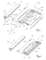
- shows an exploded view of the lighting apparatus according to the present invention;
- Figure 2
- shows a perspective view of the apparatus partially assembled;
- Figure 3
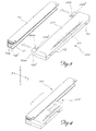
- shows a perspective view of the apparatus according to the invention with the light fixture separated from the guide rail;
- Figure 4
- shows a perspective view of the apparatus according to the invention with the light fixture inserted inside the current-conveying guide rail;
- Figure 5
- shows a schematic perspective view of a first variation of embodiment of the apparatus; and
- Figure 6
- shows a schematic perspective view of a second variation of embodiment of the apparatus.
- As shown in
Fig. 1 and assuming solely for the sake of simplification of the description and without a limiting meaning a set of three reference axes in a longitudinal direction X-X, transverse direction Y-Y and vertical direction Z-Z, respectively, the lighting device for display units according to the present invention comprises: - a
fixed rail 100, which is formed by a profiledpart 110 extending in the longitudinal direction X-X and with a substantially C-shaped cross-section; a firsttransverse arm 111 of the C is provided with twoseats 111a extending over the entire length of therail 100 and able to contain arespective cable 114a,114b for connection to the low-voltage power supply, so as to produce the two - live and neutral - poles of the power supply. the other
transverse arm 112 of the C is instead provided with arelief 112a extending in the longitudinal direction X-X and able to form a mechanical stop in the transverse direction Y-Y as will be explained more fully below.
The rail hasmoreover holes 113 intended for fixing it to a vertical surface and/or to a horizontal surface forming for example the sides or a shelf of a display unit (not shown) and/or the wall or the ceiling of a closed area. - a
lighting unit 200 formed by two half-shells - The half-
shell 210 has seats 211a,211b respectively aligned in the longitudinal direction and staggered in the transverse direction, for receiving respective low-voltage lamps 212a,212b extending in the longitudinal direction, said seats resulting in positioning of the two lamps which is staggered in the transverse direction and parallel in the longitudinal direction. - In this way each lamp may be inserted inside respective resilient conducting
parts 213 which are connected, by means ofspring clips 214 provided witharms 214a,214b extending with varying length in the transverse direction Y-Y, to the twodifferent poles 114a,114b of the electric power supply. - The half-
shell 210 also has a receiving seat 217 for thedevice 218 for adapting the low-voltage power supply to the current necessary for switching on the lamps. - The bottom half-
shell 210 has moreover twoend feet 219a extending in the transverse direction with a bottom surface having a recess 219b suitable for engagement with the saidprojection 112a on therail 110, so as to prevent thelight fixture 200 from accidentally coming out of therail 100. - The longitudinal side opposite to the rail is also provided with two
gripping parts 219 which are suitably shaped and designed to allow extraction of the lamp once it has been inserted in the transverse direction inside therail 110. - The top half-
shell 220 has twocorresponding extensions 221 in the transverse direction Y-Y provided withrespective openings 222a, 222b of different length in the same transverse direction, designed to allow thearms 214a,214b of thespring clip 214 to project outside for contact with therespective phase 114a,114b of the power supply. - As shown in
Fig. 3 and Fig. 4 , once the two half-shells, i.e. top half-shell 220 and bottom half-shell 210, have been engaged together in the vertical direction Z-Z, forming the closedlighting unit 200, the latter is inserted in the transverse direction Y-Y inside therail 110 so as to bring theelectric contacts 214a,214b of the lamps 212 into contact with therespective phase 114a,114b and cause the seat 219b of thefoot 219a to engage over therelief 112a of therail 110. - In this way the
lighting unit 200 may slide on therail 100 without any interruption of the electric power supply to the lamps, thereby allowing the latter to be displaced so as to light up different areas of a display unit and/or a space (not shown). - As shown in
Figure 5 a variation of embodiment of thelighting unit 1200 is shown, whereby the associatedfeet 1219a haverespective pins 1219c or longitudinal holes 1219d for joining together in series several adjacent lighting units in the longitudinal direction X-X, so as to extend the lighting area in the same direction. -
Figure 6 shows a further variation of embodiment of the apparatus in which the C-shaped body 1110 of the rail 1100 has athird arm 1113 extending in the transverse direction Y-Y so as to form a seat designed to allow insertion of asurface 1510 parallel to the transverse axis Y-Y and with aninclined flange 1520 projecting beyond thelight fixture 200. - Said
surfaces - If the inclined surface is to be used to carry the products, it is envisaged that the free end thereof has a raised edge 1521 (shown in broken lines in
Fig. 6 ) designed to prevent the products from falling. - It is therefore clear how, with the lighting apparatus according to the invention, it is possible to achieve effective lighting of display units and/or display areas of widely varying forms without the need for complicated electrical wiring and using low-voltage light sources which cannot be accessed by the user who is therefore guaranteed maximum safety when arranging in position and/or removing a displayed product.
- In addition, owing to the possibility of providing a modular arrangement using several single lampholders mounted on a common base, any damaged lamps can be easily replaced and the position of the light fixture varied and/or several light fixtures may be lit simultaneously.
Claims (11)
- Lighting apparatus for display units or display areas, characterized in that it comprises:- a fixed rail (100) formed by a profiled part (110) extending in the longitudinal direction (X-X) and with a substantially C-shaped cross-section, carrying a pair of cables (114a,114b) extending in the longitudinal direction for connection to the poles of an electric power supply;- a lighting unit (200;1200) formed by two half-shells (210,220) which can be joined together in the vertical direction (Z-Z) so as to form a closed box-shaped body, where one of the half-shells (210) has seats (211a,211b) for receiving respective low-voltage lamps (212a,212b) extending in the longitudinal direction (X-X), said seats resulting in positioning of the two lamps (212) which is staggered in the transverse direction and parallel in the longitudinal direction; there being provided means (219,221) for mechanically engaging together in the transverse direction (Y-Y) said rail (100) and said light fixture (200) as well as means (222a,222b) for establishing electrical contact between the light fixture (200) and a respective electric power supply cable (114a;114b).
- Apparatus according to Claim 1, characterized in that a first transverse arm (111) of the C is provided with two seats (111a) extending over the entire length of the rail (100) and able to contain a respective cable (114a,114b) for connection to the electric power supply.
- Apparatus according to Claim 2, characterized in that the other transverse arm (112) of the C has a relief (112a) extending in the longitudinal direction (X-X) and able to form a mechanical stop in the transverse direction (Y-Y) for the light fixture (200).
- Apparatus according to Claim 1, characterized in that the rail (100) has moreover holes (113) intended for fixing it to a vertical surface and/or to a horizontal surface.
- Apparatus according to Claim 1, characterized in that said half-shell (210) has seats (211a,211b) respectively aligned in the longitudinal direction and staggered in the transverse direction, for receiving respective low-voltage lamps (211a,211b) extending in the longitudinal direction.
- Apparatus according to Claim 1, characterized in that said electrical contact means comprise resilient conducting parts (213) connected, by means of spring clips (214) having arms (214a,214b) extending with varying length in the transverse direction (Y-Y), to the two different poles (114a,114b) of the electric power supply.
- Apparatus according to Claim 1, characterized in that one (210) of the two half-shells also has two end feet (219a) extending in the transverse direction with a bottom surface having a recess (219b) suitable for engagement with the said projection (112a) of the rail (110).
- Apparatus according to Claim 7, characterized in that the other half-shell (220) of said half-shells has two extensions (221) in the transverse direction (Y-Y) corresponding to the feet (219) of the first half-shell and provided with respective openings (222a,222b) of different length in the same transverse direction, designed to allow the arms (214a,214b) of the spring clip (214) to project outside for contact with the respective power supply phase (114a,114b).
- Apparatus according to Claim 1, characterized in that the associated feet (1219a) have respective pins (1219c) or longitudinal holes (1219d) for joining together in series in the longitudinal direction (X-X) several adjacent lighting units.
- Apparatus according to Claim 1, characterized in that the C-shaped body (1110) of the rail (1100) has a third arm (1113) extending in the transverse direction (Y-Y) so as to form a seat designed to allow insertion of a surface (1510) parallel to the transverse axis (Y-Y) and with an inclined flange (1520) projecting beyond the light fixture (200).
- Apparatus according to Claim 1, characterized in that said surface (1510) and said flange (1520) form together a light-guiding body (1500) which is able to absorb/reflect the light emitted by the lamps and carry an interchangeable support showing information about the product.
Applications Claiming Priority (1)
| Application Number | Priority Date | Filing Date | Title |
|---|---|---|---|
| ITMI20080715 ITMI20080715A1 (en) | 2008-04-18 | 2008-04-18 | MODULAR LIGHTING EQUIPMENT IN LOW VOLTAGE FOR EXHIBITORS AND EXPOSURE SPACES |
Publications (1)
| Publication Number | Publication Date |
|---|---|
| EP2110057A1 true EP2110057A1 (en) | 2009-10-21 |
Family
ID=40296969
Family Applications (1)
| Application Number | Title | Priority Date | Filing Date |
|---|---|---|---|
| EP09157867A Withdrawn EP2110057A1 (en) | 2008-04-18 | 2009-04-14 | Low-voltage modular lighting apparatus for display units and/or display areas. |
Country Status (2)
| Country | Link |
|---|---|
| EP (1) | EP2110057A1 (en) |
| IT (1) | ITMI20080715A1 (en) |
Cited By (5)
| Publication number | Priority date | Publication date | Assignee | Title |
|---|---|---|---|---|
| ITMI20100854A1 (en) * | 2010-05-13 | 2011-11-14 | Sarno Display S R L | LOW VOLTAGE MODULAR LIGHTING EQUIPMENT FOR EXHIBITORS AND / OR EXPOSURE SPACES |
| WO2012009822A1 (en) * | 2010-07-21 | 2012-01-26 | Visplay International Ag | Suspension device for presenting goods, having a profile rail and a primary support that can be hung therein |
| DE202012008355U1 (en) | 2012-09-03 | 2012-10-24 | Visplay International Ag | Suspension device for the presentation of goods with a current-carrying profile rail and therein suspendable primary carrier |
| FR2981434A1 (en) * | 2011-10-14 | 2013-04-19 | Oya Sourcing | LAMP |
| JP2016035829A (en) * | 2014-08-01 | 2016-03-17 | Idec株式会社 | Lighting device |
Citations (3)
| Publication number | Priority date | Publication date | Assignee | Title |
|---|---|---|---|---|
| EP1557118A1 (en) * | 2004-01-20 | 2005-07-27 | Wattohm Technologies | Shelf arrangement with integrated power supply for illumination devices |
| EP1876389A1 (en) * | 2006-07-05 | 2008-01-09 | LiteCorp Europe B.V. | Lighting system for a display apparatus |
| WO2008152973A1 (en) * | 2007-06-11 | 2008-12-18 | Kokuyo Co., Ltd. | Power supply rail, power supply system, and showcase |
-
2008
- 2008-04-18 IT ITMI20080715 patent/ITMI20080715A1/en unknown
-
2009
- 2009-04-14 EP EP09157867A patent/EP2110057A1/en not_active Withdrawn
Patent Citations (3)
| Publication number | Priority date | Publication date | Assignee | Title |
|---|---|---|---|---|
| EP1557118A1 (en) * | 2004-01-20 | 2005-07-27 | Wattohm Technologies | Shelf arrangement with integrated power supply for illumination devices |
| EP1876389A1 (en) * | 2006-07-05 | 2008-01-09 | LiteCorp Europe B.V. | Lighting system for a display apparatus |
| WO2008152973A1 (en) * | 2007-06-11 | 2008-12-18 | Kokuyo Co., Ltd. | Power supply rail, power supply system, and showcase |
Cited By (10)
| Publication number | Priority date | Publication date | Assignee | Title |
|---|---|---|---|---|
| ITMI20100854A1 (en) * | 2010-05-13 | 2011-11-14 | Sarno Display S R L | LOW VOLTAGE MODULAR LIGHTING EQUIPMENT FOR EXHIBITORS AND / OR EXPOSURE SPACES |
| EP2386796A1 (en) * | 2010-05-13 | 2011-11-16 | Sarno Display S.r.l. - Socio Unico | Low-voltage modular lighting apparatus for display units and/or areas |
| WO2012009822A1 (en) * | 2010-07-21 | 2012-01-26 | Visplay International Ag | Suspension device for presenting goods, having a profile rail and a primary support that can be hung therein |
| CN103118571A (en) * | 2010-07-21 | 2013-05-22 | 维斯普莱国际股份公司 | Suspension device for presenting goods, having a profile rail and a primary support that can be hung therein |
| DE202011110536U1 (en) | 2010-07-21 | 2014-07-08 | Visplay International Ag | Suspension device for displaying goods with a profile rail and a primary carrier which can be suspended therein |
| CN103118571B (en) * | 2010-07-21 | 2016-05-11 | 维斯普莱国际股份公司 | There is heterotypic rail and the suspension arrangement that is used for showing goods that can hang over main support wherein |
| FR2981434A1 (en) * | 2011-10-14 | 2013-04-19 | Oya Sourcing | LAMP |
| DE202012008355U1 (en) | 2012-09-03 | 2012-10-24 | Visplay International Ag | Suspension device for the presentation of goods with a current-carrying profile rail and therein suspendable primary carrier |
| WO2014032190A1 (en) | 2012-09-03 | 2014-03-06 | Visplay International Ag | Suspension device for presenting goods, having a current-carrying profiled rail and primary support which can be hung therein |
| JP2016035829A (en) * | 2014-08-01 | 2016-03-17 | Idec株式会社 | Lighting device |
Also Published As
| Publication number | Publication date |
|---|---|
| ITMI20080715A1 (en) | 2009-10-19 |
Similar Documents
| Publication | Publication Date | Title |
|---|---|---|
| KR101584928B1 (en) | Line type lighting apparatus | |
| CN103118571B (en) | There is heterotypic rail and the suspension arrangement that is used for showing goods that can hang over main support wherein | |
| US8062072B2 (en) | Tamper resistant convenience outlet | |
| US20150201762A1 (en) | Suspension Device For Presenting Goods, Having A Current-Carrying Profiled Rail And Primary Support Which Can Be Hung Therein | |
| EP2821695B1 (en) | Assembly of voltage rail, adapter and led-tube, adapter suitable for the assembly and method of mounting lighting elements | |
| KR101713054B1 (en) | Line type lighting device | |
| US20160316939A1 (en) | Rack system having an electrical supply | |
| US8480420B2 (en) | Outlet and light assembly with internal wiring connection | |
| US9537274B1 (en) | Modular power and connector system for lighting elements | |
| US20070133207A1 (en) | Movable lighting apparatus | |
| US20050173605A1 (en) | Display shelving device with integrated electrical power supply means for lighting units | |
| US2250276A (en) | Wiring device | |
| US20170074495A1 (en) | Light fixture comprising interchangeable lighting modules | |
| US10234085B2 (en) | Lighting strip system | |
| WO2013180914A1 (en) | Connector assembly with polarity correction/protection | |
| KR200481900Y1 (en) | Lighting system | |
| ES2742439T3 (en) | Lighting system | |
| EP1757858A2 (en) | Illumination device with modular and movable lamp holder for display cabinets and/or display spaces | |
| KR20100089176A (en) | Lighting apparatus having sliding type lighting module | |
| ITMI20080715A1 (en) | MODULAR LIGHTING EQUIPMENT IN LOW VOLTAGE FOR EXHIBITORS AND EXPOSURE SPACES | |
| JP6111127B2 (en) | Outlet, plug, and lighting device | |
| JP3158658U (en) | Display shelf lighting equipment | |
| KR20090005498A (en) | Cable Wiring Devices and Luminaire Systems With Them | |
| KR100936450B1 (en) | Fluorescent lamp with sliding power connection | |
| JP2016197512A (en) | Led lighting fixture |
Legal Events
| Date | Code | Title | Description |
|---|---|---|---|
| PUAI | Public reference made under article 153(3) epc to a published international application that has entered the european phase |
Free format text: ORIGINAL CODE: 0009012 |
|
| AK | Designated contracting states |
Kind code of ref document: A1 Designated state(s): AT BE BG CH CY CZ DE DK EE ES FI FR GB GR HR HU IE IS IT LI LT LU LV MC MK MT NL NO PL PT RO SE SI SK TR |
|
| 17P | Request for examination filed |
Effective date: 20100414 |
|
| 17Q | First examination report despatched |
Effective date: 20110330 |
|
| GRAP | Despatch of communication of intention to grant a patent |
Free format text: ORIGINAL CODE: EPIDOSNIGR1 |
|
| RIC1 | Information provided on ipc code assigned before grant |
Ipc: F21V 23/06 20060101ALI20130614BHEP Ipc: F21V 21/35 20060101ALI20130614BHEP Ipc: A47F 11/10 20060101ALI20130614BHEP Ipc: F21V 33/00 20060101AFI20130614BHEP |
|
| INTG | Intention to grant announced |
Effective date: 20130711 |
|
| RIN1 | Information on inventor provided before grant (corrected) |
Inventor name: NOBILI, RENATO |
|
| STAA | Information on the status of an ep patent application or granted ep patent |
Free format text: STATUS: THE APPLICATION IS DEEMED TO BE WITHDRAWN |
|
| 18D | Application deemed to be withdrawn |
Effective date: 20131122 |