EP2109902B1 - Battery cell - Google Patents
Battery cell Download PDFInfo
- Publication number
- EP2109902B1 EP2109902B1 EP08727482.5A EP08727482A EP2109902B1 EP 2109902 B1 EP2109902 B1 EP 2109902B1 EP 08727482 A EP08727482 A EP 08727482A EP 2109902 B1 EP2109902 B1 EP 2109902B1
- Authority
- EP
- European Patent Office
- Prior art keywords
- terminal
- battery cell
- lid
- terminal assembly
- electrochemical cell
- Prior art date
- Legal status (The legal status is an assumption and is not a legal conclusion. Google has not performed a legal analysis and makes no representation as to the accuracy of the status listed.)
- Active
Links
Images







Classifications
-
- H—ELECTRICITY
- H01—ELECTRIC ELEMENTS
- H01M—PROCESSES OR MEANS, e.g. BATTERIES, FOR THE DIRECT CONVERSION OF CHEMICAL ENERGY INTO ELECTRICAL ENERGY
- H01M50/00—Constructional details or processes of manufacture of the non-active parts of electrochemical cells other than fuel cells, e.g. hybrid cells
- H01M50/10—Primary casings; Jackets or wrappings
- H01M50/147—Lids or covers
-
- H—ELECTRICITY
- H01—ELECTRIC ELEMENTS
- H01M—PROCESSES OR MEANS, e.g. BATTERIES, FOR THE DIRECT CONVERSION OF CHEMICAL ENERGY INTO ELECTRICAL ENERGY
- H01M50/00—Constructional details or processes of manufacture of the non-active parts of electrochemical cells other than fuel cells, e.g. hybrid cells
- H01M50/10—Primary casings; Jackets or wrappings
- H01M50/147—Lids or covers
- H01M50/166—Lids or covers characterised by the methods of assembling casings with lids
- H01M50/169—Lids or covers characterised by the methods of assembling casings with lids by welding, brazing or soldering
-
- H—ELECTRICITY
- H01—ELECTRIC ELEMENTS
- H01M—PROCESSES OR MEANS, e.g. BATTERIES, FOR THE DIRECT CONVERSION OF CHEMICAL ENERGY INTO ELECTRICAL ENERGY
- H01M50/00—Constructional details or processes of manufacture of the non-active parts of electrochemical cells other than fuel cells, e.g. hybrid cells
- H01M50/10—Primary casings; Jackets or wrappings
- H01M50/172—Arrangements of electric connectors penetrating the casing
- H01M50/174—Arrangements of electric connectors penetrating the casing adapted for the shape of the cells
- H01M50/176—Arrangements of electric connectors penetrating the casing adapted for the shape of the cells for prismatic or rectangular cells
-
- H—ELECTRICITY
- H01—ELECTRIC ELEMENTS
- H01M—PROCESSES OR MEANS, e.g. BATTERIES, FOR THE DIRECT CONVERSION OF CHEMICAL ENERGY INTO ELECTRICAL ENERGY
- H01M50/00—Constructional details or processes of manufacture of the non-active parts of electrochemical cells other than fuel cells, e.g. hybrid cells
- H01M50/50—Current conducting connections for cells or batteries
- H01M50/543—Terminals
- H01M50/547—Terminals characterised by the disposition of the terminals on the cells
- H01M50/55—Terminals characterised by the disposition of the terminals on the cells on the same side of the cell
-
- H—ELECTRICITY
- H01—ELECTRIC ELEMENTS
- H01M—PROCESSES OR MEANS, e.g. BATTERIES, FOR THE DIRECT CONVERSION OF CHEMICAL ENERGY INTO ELECTRICAL ENERGY
- H01M50/00—Constructional details or processes of manufacture of the non-active parts of electrochemical cells other than fuel cells, e.g. hybrid cells
- H01M50/50—Current conducting connections for cells or batteries
- H01M50/543—Terminals
- H01M50/552—Terminals characterised by their shape
- H01M50/553—Terminals adapted for prismatic, pouch or rectangular cells
-
- H—ELECTRICITY
- H01—ELECTRIC ELEMENTS
- H01M—PROCESSES OR MEANS, e.g. BATTERIES, FOR THE DIRECT CONVERSION OF CHEMICAL ENERGY INTO ELECTRICAL ENERGY
- H01M50/00—Constructional details or processes of manufacture of the non-active parts of electrochemical cells other than fuel cells, e.g. hybrid cells
- H01M50/50—Current conducting connections for cells or batteries
- H01M50/543—Terminals
- H01M50/562—Terminals characterised by the material
-
- H—ELECTRICITY
- H01—ELECTRIC ELEMENTS
- H01M—PROCESSES OR MEANS, e.g. BATTERIES, FOR THE DIRECT CONVERSION OF CHEMICAL ENERGY INTO ELECTRICAL ENERGY
- H01M50/00—Constructional details or processes of manufacture of the non-active parts of electrochemical cells other than fuel cells, e.g. hybrid cells
- H01M50/50—Current conducting connections for cells or batteries
- H01M50/543—Terminals
- H01M50/564—Terminals characterised by their manufacturing process
- H01M50/566—Terminals characterised by their manufacturing process by welding, soldering or brazing
-
- Y—GENERAL TAGGING OF NEW TECHNOLOGICAL DEVELOPMENTS; GENERAL TAGGING OF CROSS-SECTIONAL TECHNOLOGIES SPANNING OVER SEVERAL SECTIONS OF THE IPC; TECHNICAL SUBJECTS COVERED BY FORMER USPC CROSS-REFERENCE ART COLLECTIONS [XRACs] AND DIGESTS
- Y02—TECHNOLOGIES OR APPLICATIONS FOR MITIGATION OR ADAPTATION AGAINST CLIMATE CHANGE
- Y02E—REDUCTION OF GREENHOUSE GAS [GHG] EMISSIONS, RELATED TO ENERGY GENERATION, TRANSMISSION OR DISTRIBUTION
- Y02E60/00—Enabling technologies; Technologies with a potential or indirect contribution to GHG emissions mitigation
- Y02E60/10—Energy storage using batteries
-
- Y—GENERAL TAGGING OF NEW TECHNOLOGICAL DEVELOPMENTS; GENERAL TAGGING OF CROSS-SECTIONAL TECHNOLOGIES SPANNING OVER SEVERAL SECTIONS OF THE IPC; TECHNICAL SUBJECTS COVERED BY FORMER USPC CROSS-REFERENCE ART COLLECTIONS [XRACs] AND DIGESTS
- Y02—TECHNOLOGIES OR APPLICATIONS FOR MITIGATION OR ADAPTATION AGAINST CLIMATE CHANGE
- Y02P—CLIMATE CHANGE MITIGATION TECHNOLOGIES IN THE PRODUCTION OR PROCESSING OF GOODS
- Y02P70/00—Climate change mitigation technologies in the production process for final industrial or consumer products
- Y02P70/50—Manufacturing or production processes characterised by the final manufactured product
-
- Y—GENERAL TAGGING OF NEW TECHNOLOGICAL DEVELOPMENTS; GENERAL TAGGING OF CROSS-SECTIONAL TECHNOLOGIES SPANNING OVER SEVERAL SECTIONS OF THE IPC; TECHNICAL SUBJECTS COVERED BY FORMER USPC CROSS-REFERENCE ART COLLECTIONS [XRACs] AND DIGESTS
- Y10—TECHNICAL SUBJECTS COVERED BY FORMER USPC
- Y10T—TECHNICAL SUBJECTS COVERED BY FORMER US CLASSIFICATION
- Y10T29/00—Metal working
- Y10T29/49—Method of mechanical manufacture
- Y10T29/49002—Electrical device making
- Y10T29/49108—Electric battery cell making
Definitions
- the present disclosure relates to the field of batteries and battery systems. More specifically, the present disclosure relates to batteries or cells (e.g., lithium-ion batteries).
- batteries or cells e.g., lithium-ion batteries.
- JP 2005-190697 A relates to an electrochemical cell comprising a can having a first and a second end, a first wound element provided within the can, a terminal stud configured to act as a first terminal of the electrochemical cell, and a first terminal assembly directly coupled to the first wound element and including a terminal post configured to act as a second terminal of the electrochemical cell.
- the electrochemical cell further comprises a boss that defines an aperture through which the terminal post extends, wherein the boss at least partially surrounds the terminal post, and a bushing coupled to the terminal post.
- batteries or cells for use in vehicles such as automobiles.
- lead- acid batteries have been used in starting, lighting, and ignition applications.
- hybrid electric vehicles are being developed which utilize a battery (e.g., a lithium-ion or nickel-metal-hydride battery) in combination with other systems (e.g., an internal combustion engine) to provide power for the vehicle.
- a battery generally includes multiple terminals (e.g., a positive terminal and a negative terminal, etc.) through which the battery is electrically connected to other batteries or other components.
- a battery may have terminals that protrude from the battery surface. These terminals are provided as separate elements that are coupled to other battery components (e.g., by welding to a battery cover). This adds to the manufacturing process, as well as increases cost. The integrity of such coupling mechanisms may also present issues over the life of the battery.
- a battery that generally includes a jellyroll connected to the terminals by intermediate members (e.g. terminal tabs). Connecting the terminals in this fashion adds to the manufacturing process, as well as increases costs. Terminal tabs also increase current resistance. It would be advantageous to eliminate the need for such terminal tabs to remove the additional components and manufacturing costs and time associated with such components (e.g., to reduce the number of parts in the battery and to eliminate the need to handle and assemble the components during manufacturing), to reduce resistance, and generally improve the conductive connection between the jellyroll and the terminals.
- weld various battery components utilizing conventional welding techniques.
- Such welds are not highly resistant to vibration, or environmentally friendly.
- Such welds can also make it difficult to introduce electrolyte into a battery cell.
- Certain welds also require the use of additional materials such as metallic plating.
- non-conventional welds e.g. sonic welds
- Such non-conventional welds also leave fill paths between electrode layers to allow electrolyte to be more easily introduced into the battery cell, and eliminate the need for intermediate material such as metallic plating.
- a battery cell that includes one or more terminals that are integrally formed with the body or cover of the battery. It would also be advantageous to directly conductively couple the terminals to the jellyroll utilizing non-conventional welds such as sonic welds.
- the present invention relates to a battery cell comprising, a can having a first end and a second end, a first wound element provided within the can, a terminal stud formed as part of the can and extending from the first end and configured to act as a first terminal of the electrochemical cell, and a first terminal assembly directly coupled to the first wound element and including a terminal post configured to act as a second terminal of the electrochemical cell.
- the first wound element is wound around a mandrel.
- the first end of the can includes a boss that defines an aperture through which the terminal post extends, wherein the boss at least partially surrounds the terminal post and a bushing coupled to the terminal post.
- the bushing is configured to insulate the terminal post from the can.
- the first terminal assembly is at least partially inserted into an opening of the mandrel, wherein the opening is defined by at least a portion of the mandrel.
- the present invention further relates to a method of manufacturing such a battery cell comprising inserting a first terminal assembly at least partially into an opening of a mandrel, wherein at least a portion of the mandrel defines the opening, welding a terminal assembly to a first wound element, providing a bushing in contact with the first terminal assembly around a terminal post, providing a first terminal stud at a first end of a can, and inserting the bushing, at least a portion of the first terminal assembly through an aperture formed in the first end of the can, the aperture being defined by a boss and extending from the first end of the can, wherein the bushing act to isolate the terminal assembly from the boss.
- the term "coupled” means the joining of two members directly or indirectly to one another. Such joining may be stationary in nature or movable in nature. Such joining may be achieved with the two members or the two members and any additional intermediate members being integrally formed as a single unitary body with one another or with the two members, or the two members and any additional intermediate members being attached, connected or otherwise joined to one another. Such joining may be permanent in nature or may be removable or releasable in nature.
- a vehicle 110 is shown according to an exemplary embodiment and includes a battery module 120. Size, shape, configuration and location of battery module 120 and the type of vehicle 110 may vary according to various exemplary embodiments.
- vehicle 110 is shown as an automobile, according to various exemplary embodiments, the vehicle may comprise a wide variety of different types of vehicles, including, among others, motorcycles, buses, recreational vehicles, boats and the like.
- vehicle 110 is a hybrid vehicle or electric vehicle.
- Battery module 120 includes one or more electrochemical cells or batteries, shown as battery cells 130 (e.g., lithium-ion batteries, NiMH, lithium polymer batteries, etc.). Each battery cell 130 may be positioned within a housing that may include such features of a battery system such as a battery management system, cooling fan, plenum assembly, etc. Other battery module configurations may be used in accordance with various other exemplary embodiments.
- battery cells 130 e.g., lithium-ion batteries, NiMH, lithium polymer batteries, etc.
- Each battery cell 130 may be positioned within a housing that may include such features of a battery system such as a battery management system, cooling fan, plenum assembly, etc.
- Other battery module configurations may be used in accordance with various other exemplary embodiments.
- FIGS. 3-7 Shown in FIGS. 3-7 is a first exemplary embodiment of a battery cell 130 including a first end 140 and a second end 150, and a first terminal post 160 and a terminal stud 170 positioned substantially near first end 140 of battery cell 130.
- battery cell 130 is an oval cell.
- the battery cell may also be a round cell or other suitable configuration.
- battery cell 130 is a lithium-ion cell.
- the battery cell may be a lithium-polymer cell.
- the battery cell includes a suitable lithium-containing film.
- the film includes LiMnO 2 , LiFePO 4 or LiCoO 2 .
- the lithium-containing film is 50-1000 ⁇ m in thickness, and more preferably 150 ⁇ m. In various embodiments, e.g., for high power designs, the lithium-containing film is approximately 50-100 ⁇ m in thickness.
- the lithium- containing film may be made using a wet or dry manufacturing process.
- battery cell 130 is capable of having a fully-charged voltage of 0-5 volts.
- battery cell 130 includes first terminal post 160, a lid 180, and a can 190 that includes terminal stud 170.
- Can 190 and lid 180 may be constructed from any number of suitable materials.
- the can and lid are each constructed from one or more conductive materials including, without limitation, aluminum, aluminum alloy, steel, steel alloy, titanium or titanium alloy. It should be appreciated, however, that the can and lid do not need to be constructed of identical or similar materials.
- the lid may be constructed of one or more non-conductive materials.
- battery cell 130 includes a first wound element 200 conductively coupled to a first terminal assembly 210.
- first wound element 200 includes conductive foils such as metallic foils.
- first wound element 200 includes one or more copper foils and first terminal post 160 is negatively charged.
- first wound element 200 is at least partially conductively coupled to first terminal assembly 210.
- first wound element 200 is sonically welded to first terminal assembly 210.
- first wound element 200 is sonically welded on opposing sides of first terminal assembly 210.
- the first wound element may be sonically welded to the first terminal assembly in one or more locations.
- the first wound element may be conductively and/or mechanically coupled to the first terminal assembly in a variety of other suitable ways including laser welding, or other more conventional welding techniques.
- a bushing 220 at least partially surrounds the perimeter of first terminal post 160.
- bushing 220 is configured and positioned to substantially insulate at least first terminal post 160 from can 190 during and/or after assembly of battery cell 130.
- bushing 220 is also configured to at least partially insulate other components of first terminal assembly 210 and/or first wound element 200 from can 190.
- the bushing may be constructed of any material with suitable insulating properties.
- bushing 220 is constructed substantially of rubber.
- terminal stud 170 and an aperture 230 are provided substantially at first end 240 of can 190.
- aperture 230 is at least partially defined by a generally cylindrical body (e.g. boss) that extends from first end 240 of can 190.
- aperture 230 may be any suitable shape.
- can 190 and aperture 230 are collectively provided around a number of components of battery cell 130 including at least a portion of first terminal assembly 210, including a portion of first terminal post 160, and at least a portion of bushing 220 such that at least a portion of first terminal assembly 210 and bushing 220 are at least partially surrounded by aperture 230.
- lid 180 is configured to substantially envelope margins of a second end 250 of can 190.
- the battery cell may include at least one additional terminal post, terminal stud and/or aperture (e.g. boss).
- a second boss may be provided at the first end of the can, and configured to at least partially surround a second bushing and a second terminal post.
- the first terminal post and the second terminal post are similarly charged.
- the first terminal post and second terminal post may both be negative terminals.
- a second terminal stud provided at the first end of the can and the first terminal stud are similarly charged.
- the first terminal stud and the second terminal stud may be positive.
- battery cell 130 also includes an insulator 260 configured to fit substantially around at least a portion of aperture 230.
- the insulator may be constructed of any material with suitable insulating properties.
- insulator 260 comprises a polymer or plastic.
- battery cell 130 also includes a second wound element 270.
- second wound element 270 includes conductive foils such as metallic foils.
- second wound element 270 includes aluminum foils.
- second wound element 270 is conductively coupled directly to can 190.
- a welding area 280 of second wound element 270 is sonically welded to can 190 near second end 250 of can 190.
- the second wound element may be conductively coupled to the can in any number of locations in any suitable way, e.g., by laser welding.
- second wound element 270 is conductively coupled to a second terminal assembly 290.
- at least welding area 280 of second wound element 270 is sonically welded to second terminal assembly 290.
- the second wound element may be conductively coupled to the second terminal assembly in any number of locations in any suitable way, e.g. laser welding.
- battery cell 130 may include a lid 300.
- lid 300 defines a lid aperture 310.
- lid 300 and lid aperture 310 are collectively provided around a number of components of battery cell 130 including at least a portion of second terminal assembly 290, with the lid aperture provided substantially around a perimeter of a second terminal post 320 of second terminal assembly 290.
- the second terminal assembly and/or the second terminal post extending through the lid aperture are at least partially surrounded by an insulated member.
- the lid aperture includes a boss or collar that may be crimped, pressed, tightened and/or shrunk against the insulating member and/or second terminal assembly to help couple the second terminal assembly to the lid.
- the can and the lid may comprise any variety of configurations.
- the lid may be relatively shallow in depth relative to the can.
- the lid may have one or more relatively longer sides.
- the lid is configured to at least partially envelope a cross-sectional perimeter of the can.
- one or more of the sides of the can may overlap one or more of the sides of the lid.
- one or more of the sides of the can may be configured to abut one or more of the sides of the lid.
- the can and the lid may be coupled in any number of suitable ways.
- at least a portion of the lid may be heated to expansion, fit over a cross-sectional perimeter of the can and then allowed to cool and shrink to help create a seal between the can and the lid.
- the lid may be welded to the can.
- one or more portions of the lid may be laser welded or sonically welded to one or more portions of the can.
- an adhesive or epoxy may be utilized to couple the lid to the can.
- plastic may be utilized to couple the lid to the can.
- at least the second end of the can may be formed, coated, or otherwise at least partially covered with a plastic.
- the second end of the can may be dipped in a plastic and/or a plastic (e.g. tape) may be at least partially wrapped around the can substantially near the second end of the can.
- the lid may be heated to expansion and fit over a cross-sectional perimeter of the can covered or coated with plastic.
- the heated lid may help at least partially melt the plastic as it comes into proximity to it.
- the plastic helps create a seal between the can and the lid.
- the plastic material may comprise a polyethylene or other ethylene material or a polyolephin material.
- the battery cell includes at least one pressure release system to help vent gases and/or relieve pressure as and/or after the battery cell begins to fail or otherwise malfunction.
- the pressure release system is also configured to cut the battery cell from a current path of a battery module comprising the battery cell without substantially disrupting the current path of the battery module.
- the seal between the can and the lid helps relieve and/or release pressure.
- at least a portion of the battery cell may realize an elevation in temperature and/or internal pressure.
- the increase in battery cell temperature and/or pressure helps cause the seal between the lid and can to at least partially deteriorate and/or the lid and can to at least partially separate.
- Such a pressure release system may allow pressurized gases inside the battery cell to escape.
- the pressure release system may also be configured to interface with a bus bar to disrupt a current path of the battery cell without significantly interrupting the current path of a battery module comprising the battery cell.
- the lid includes a collar.
- the battery cell and bus bar may be relatively positioned such that, when the lid moves relative to the can, the collar is moved into a knife/blade connection on the bus bar to cut the current path of the battery cell without significantly disrupting the current path of the battery module comprising the battery cell.
- the can includes a weakened area designed to rupture if and when pressure inside the battery cell reaches a certain level.
- a portion of a side or the first end of the can and/or second end of the can may have a reduced thickness to help the can rupture more easily to relieve and/or release pressure inside the battery cell when it reaches a certain level.
- the weakened area may be provided by scoring or any other suitable methods of weakening a portion of the can, or may be a separate material provided in the can.
- the weakened area may help disrupt the current path to the battery cell.
- the weakened area may be located substantially around the second terminal post of the battery cell such that a pressure condition resulting in a rupture causes the second terminal post to conductively and/or mechanically separate from the battery cell such that the battery cell is cut out of the current path of the battery module comprising the battery cell without substantially disrupting the current path of the battery module.
- At least first terminal assembly 210 is associated with a mandrel 330 to produce a mandrel assembly 340.
- mandrel 330 is constructed or formed of a plastic material.
- at least a portion of mandrel 330 defines at least one opening 350 that is configured to receive at least a portion of at least first terminal assembly 210.
- first terminal assembly 210 may be at least partially inserted into opening 350.
- second terminal assembly 290 is at least partially inserted into opening 350 or another opening. While FIG.
- first and second terminal assemblies 210/290 positioned at opposing ends of mandrel 330
- the mandrel may be operatively connected with any number of terminal assemblies, and multiple terminal assemblies including the first and second terminal assemblies may be positioned at or substantially near the same end of the mandrel.
- Each terminal assembly may be operatively connected to the mandrel in any number of suitable ways.
- each terminal assembly may be inserted into the aperture and molded, glued, heat-sealed and/or otherwise coupled to the mandrel.
- the mandrel assembly is placed on a winding machine (not shown).
- electrodes including the first wound element and at least one separator (not shown) are wound around mandrel 330 such that at least a portion of the first wound element overlaps at least a portion of first terminal assembly 210.
- at least a portion of the first wound element is conductively coupled to first terminal assembly 210.
- at least a portion of first wound element is sonically welded to first terminal assembly 210 at 20 - 40 kHz.
- the first wound element and the second wound element is wrapped or otherwise covered with a sheath (not shown) to produce an electrode assembly.
- the sheath may be a shrink wrap or other insulating material such as polypropylene, polyethylene, green tape or any other material with suitable insulating qualities.
- the bushing is provided around the first terminal post, the electrode assembly is inserted into a heated can such that at least a portion of the first terminal post passes through the boss or other opening in the can provided therefor.
- the can and the boss are heated to approximately 100 deg C and allowed to cool after insertion of the electrode assembly into the can. As the can and the boss cool, the can and the boss are allowed to contract around at least a portion of the electrode assembly.
- a screw tap may be releasably connected to the first terminal post.
- a screw tap may be inserted into an end of the first terminal post. The screw tap may then be utilized to help pull the electrode assembly into the can, and/or the first terminal post, into the boss and/or other opening provided therefor.
- At least a portion of the second wound element is conductively coupled to the can. In various embodiments, at least a portion of the second wound element is sonically welded to can at 20-40 kHz.
- electrolyte is inserted into the can or otherwise introduced to the electrode assembly and the lid is used to at least partially enclose the second end of the can. The electrolyte may also be inserted into the can after the lid is utilized to at least partially enclose the second end of the can.
- the lid and/or the can may include a fill port.
- much of the battery cell assembly may be performed at one machine, and less floor space is needed to assemble the battery cell.
- multiple battery cells may be conductively and/or mechanically coupled together with swedged collars surrounding a positive terminal apparatus from one battery cell and a negative terminal apparatus from another battery cell.
- the battery cell includes at least one terminal assembly, such as first terminal assembly 210 and/or second terminal assembly 290. At least one of the first and second terminal assemblies 210/290 includes a stud 350, a welding surface 360 and a terminal post 370.
- stud 350 is configured for insertion into a mandrel.
- the cross section of stud 350 is generally rectangular.
- the stud may be configured of any suitable geometric shapes including, without limitation, a trapezoidal or cylindrical shape.
- stud 350 is a single member.
- the stud may include a plurality of members when desired, e.g., where it is desirable to use less material.
- stud 350 is connected to the welding surface 360.
- welding surface 360 is configured to provide a surface to which at least a portion of a wound element may be mechanically and/or conductively coupled.
- welding surface 360 extends substantially laterally from stud 350.
- at least a portion of the welding surface may abut the mandrel to help prevent movement of the terminal assembly relative to the mandrel.
- the welding surface extends laterally from the stud to a position substantially aligned with a center layer of at least one wound element.
- welding surface 360 is configured to overlap a margin of the mandrel. In various embodiments, welding surface 360 may extend beyond the margin of the mandrel and into one or more wound elements.
- the one or more terminal assemblies may be operatively associated with the mandrel while electrodes are wound around the mandrel. In various embodiments, one or more portions of the electrodes may then be conductively coupled to each terminal assembly. For example, the electrodes may be laser, friction and/or induction welded to each terminal assembly.
- terminal post 370 is coupled to welding surface 360. In various embodiments, terminal post 370 is configured to provide an external terminal for a battery cell.
- the terminal post may be any suitable geometric shape. In various embodiments, the terminal post is a bar or round stock. For example, terminal post 370 in FIGS. 13-18 is shown as a smooth cylindrical post.
- the terminal post is a blade, a threaded post or another suitable configuration.
- Terminal post 370 may be coupled to welding surface 360 in any number of ways.
- the terminal post is spun welded to the welding surface.
- terminal assembly 350 also includes one or more tapered portions 380.
- one or more tapered portions 380 connect stud 350 to welding surface 360.
- tapered portion 380 includes one or more sides inclined from one or more sides of stud 350 to one or more sides of welding surface 360.
- tapered portion 380 is inclined or otherwise configured to help prevent damage to one or more of the electrodes of the wound elements.
- Tapered portion 380 may also improve the connection between the mandrel and terminal assembly 210/290 and/or between one or more wound elements and terminal assembly 210/290.
- Welding surface 360, stud 350 and/or tapered portion 380 may be coupled in any variety of suitable ways.
- welding surface 360, stud 350 and/or tapered portion 380 may be a stamped piece.
- each terminal assembly 210/290 is constructed or otherwise formed of conductive material such as aluminum, copper and/or an alloy comprising aluminum and/or copper.
- the second terminal assembly may be constructed of aluminum and/or an aluminum alloy such as AlMg 3
- the first terminal assembly may be constructed of copper and/or a copper alloy such as C110.
- Elements shown as integrally formed may be constructed of multiple parts or element(e.e the can and the terminal stud).
Landscapes
- Chemical & Material Sciences (AREA)
- Chemical Kinetics & Catalysis (AREA)
- Electrochemistry (AREA)
- General Chemical & Material Sciences (AREA)
- Engineering & Computer Science (AREA)
- Manufacturing & Machinery (AREA)
- Connection Of Batteries Or Terminals (AREA)
- Sealing Battery Cases Or Jackets (AREA)
Description
- This application claims the benefit of
U.S. Provisional Patent Application Nos. 60/884,151 filed January 9, 2007 60/956,539 filed August 17, 2007 - The present disclosure relates to the field of batteries and battery systems. More specifically, the present disclosure relates to batteries or cells (e.g., lithium-ion batteries).
-
JP 2005-190697 A
It is known to provide batteries or cells for use in vehicles such as automobiles. For example, lead- acid batteries have been used in starting, lighting, and ignition applications. More recently, hybrid electric vehicles are being developed which utilize a battery (e.g., a lithium-ion or nickel-metal-hydride battery) in combination with other systems (e.g., an internal combustion engine) to provide power for the vehicle. - It is known that a battery generally includes multiple terminals (e.g., a positive terminal and a negative terminal, etc.) through which the battery is electrically connected to other batteries or other components. A battery may have terminals that protrude from the battery surface. These terminals are provided as separate elements that are coupled to other battery components (e.g., by welding to a battery cover). This adds to the manufacturing process, as well as increases cost. The integrity of such coupling mechanisms may also present issues over the life of the battery.
- It is known to provide a battery that generally includes a jellyroll connected to the terminals by intermediate members (e.g. terminal tabs). Connecting the terminals in this fashion adds to the manufacturing process, as well as increases costs. Terminal tabs also increase current resistance. It would be advantageous to eliminate the need for such terminal tabs to remove the additional components and manufacturing costs and time associated with such components (e.g., to reduce the number of parts in the battery and to eliminate the need to handle and assemble the components during manufacturing), to reduce resistance, and generally improve the conductive connection between the jellyroll and the terminals.
- It is known to weld various battery components utilizing conventional welding techniques. However, such welds are not highly resistant to vibration, or environmentally friendly. Such welds can also make it difficult to introduce electrolyte into a battery cell. Certain welds also require the use of additional materials such as metallic plating. It would advantageous to eliminate the use of such conventional welds in favor of non-conventional welds (e.g. sonic welds) to obtain a superior connection, superior pull-out strength, higher resistance to vibration and an efficient and repeatable process that is environmentally friendly. Such non-conventional welds also leave fill paths between electrode layers to allow electrolyte to be more easily introduced into the battery cell, and eliminate the need for intermediate material such as metallic plating.
- Accordingly, it would be advantageous to provide a battery cell that includes one or more terminals that are integrally formed with the body or cover of the battery. It would also be advantageous to directly conductively couple the terminals to the jellyroll utilizing non-conventional welds such as sonic welds.
- The present invention relates to a battery cell comprising, a can having a first end and a second end, a first wound element provided within the can, a terminal stud formed as part of the can and extending from the first end and configured to act as a first terminal of the electrochemical cell, and a first terminal assembly directly coupled to the first wound element and including a terminal post configured to act as a second terminal of the electrochemical cell. The first wound element is wound around a mandrel. The first end of the can includes a boss that defines an aperture through which the terminal post extends, wherein the boss at least partially surrounds the terminal post and a bushing coupled to the terminal post. The bushing is configured to insulate the terminal post from the can. The first terminal assembly is at least partially inserted into an opening of the mandrel, wherein the opening is defined by at least a portion of the mandrel.
- The present invention further relates to a method of manufacturing such a battery cell comprising inserting a first terminal assembly at least partially into an opening of a mandrel, wherein at least a portion of the mandrel defines the opening, welding a terminal assembly to a first wound element, providing a bushing in contact with the first terminal assembly around a terminal post, providing a first terminal stud at a first end of a can, and inserting the bushing, at least a portion of the first terminal assembly through an aperture formed in the first end of the can, the aperture being defined by a boss and extending from the first end of the can, wherein the bushing act to isolate the terminal assembly from the boss.
- The accompanying drawings, which are incorporated in and constitute a part of the specification, illustrate embodiments of the invention and together with the detailed description given below, serve to explain the principles of the invention.
-
Fig. 1 is a perspective view of a vehicle including a battery module according to an exemplary embodiment. -
Fig. 2 is an isometric view of a battery module according to an exemplary embodiment. -
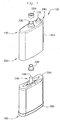
Fig. 3 is an isometric view of an exemplary embodiment of a battery cell. -
Fig. 4 is a partially exploded isometric view of an exemplary embodiment of a battery cell. -
Fig. 5 is a partially exploded isometric view of an exemplary embodiment of a battery cell. -
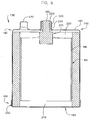
Fig. 6 is a first cross sectional view of an exemplary embodiment of a battery cell. -
Fig. 7 is a second cross sectional view of an exemplary embodiment of a battery cell. -
Fig. 8 is a partially exploded isometric view of a not claimed, second exemplary embodiment of a battery cell. -
Fig. 9 is an isometric view of a not claimed, second exemplary embodiment of an electrode assembly. -
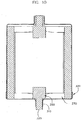
Fig. 10 is a first cross sectional view of a not claimed, second exemplary embodiment of a battery cell. -
Fig. 11 is a second cross sectional view of a not claimed, second exemplary embodiment of a battery cell. -
Fig. 12 is a partially exploded isometric view of an exemplary embodiment of a mandrel assembly. -
Fig. 13 is a front view of an exemplary embodiment of a terminal assembly. -
Fig. 14 is a top view of an exemplary embodiment of a terminal assembly. -
Fig. 15 is a side view of an exemplary embodiment of a terminal assembly. -
Fig. 16 is a bottom view of an exemplary embodiment of a terminal assembly. -
Fig. 17 is a first isometric view of an exemplary embodiment of a terminal assembly. -
Fig. 18 is a second isometric view of an exemplary embodiment of a terminal assembly. - For the purposes of this disclosure, the term "coupled" means the joining of two members directly or indirectly to one another. Such joining may be stationary in nature or movable in nature. Such joining may be achieved with the two members or the two members and any additional intermediate members being integrally formed as a single unitary body with one another or with the two members, or the two members and any additional intermediate members being attached, connected or otherwise joined to one another. Such joining may be permanent in nature or may be removable or releasable in nature.
- Referring to
FIG. 1 , avehicle 110 is shown according to an exemplary embodiment and includes abattery module 120. Size, shape, configuration and location ofbattery module 120 and the type ofvehicle 110 may vary according to various exemplary embodiments. For example, whilevehicle 110 is shown as an automobile, according to various exemplary embodiments, the vehicle may comprise a wide variety of different types of vehicles, including, among others, motorcycles, buses, recreational vehicles, boats and the like. According to an exemplary embodiment,vehicle 110 is a hybrid vehicle or electric vehicle. - Referring to
FIG. 2 , abattery module 120 is shown according to an exemplary embodiment.Battery module 120 includes one or more electrochemical cells or batteries, shown as battery cells 130 (e.g., lithium-ion batteries, NiMH, lithium polymer batteries, etc.). Eachbattery cell 130 may be positioned within a housing that may include such features of a battery system such as a battery management system, cooling fan, plenum assembly, etc. Other battery module configurations may be used in accordance with various other exemplary embodiments. - Shown in
FIGS. 3-7 is a first exemplary embodiment of abattery cell 130 including afirst end 140 and asecond end 150, and a firstterminal post 160 and aterminal stud 170 positioned substantially nearfirst end 140 ofbattery cell 130. - In various embodiments,
battery cell 130 is an oval cell. The battery cell may also be a round cell or other suitable configuration. In various embodiments,battery cell 130 is a lithium-ion cell. The battery cell may be a lithium-polymer cell. In various embodiments, the battery cell includes a suitable lithium-containing film. For example, in various exemplary embodiments, the film includes LiMnO2, LiFePO4 or LiCoO2. In various embodiments, the lithium-containing film is 50-1000 µm in thickness, and more preferably 150 µm. In various embodiments, e.g., for high power designs, the lithium-containing film is approximately 50-100 µm in thickness. The lithium- containing film may be made using a wet or dry manufacturing process. In various embodiments,battery cell 130 is capable of having a fully-charged voltage of 0-5 volts. - In exemplary embodiments,
battery cell 130 includes firstterminal post 160, alid 180, and a can 190 that includesterminal stud 170. Can 190 andlid 180 may be constructed from any number of suitable materials. Preferably, the can and lid are each constructed from one or more conductive materials including, without limitation, aluminum, aluminum alloy, steel, steel alloy, titanium or titanium alloy. It should be appreciated, however, that the can and lid do not need to be constructed of identical or similar materials. In various embodiments, the lid may be constructed of one or more non-conductive materials. - In one embodiment,
battery cell 130 includes afirst wound element 200 conductively coupled to a firstterminal assembly 210. In one exemplary embodiment,first wound element 200 includes conductive foils such as metallic foils. For example, in one exemplary embodiment,first wound element 200 includes one or more copper foils and firstterminal post 160 is negatively charged. - In various embodiments,
first wound element 200 is at least partially conductively coupled to firstterminal assembly 210. In one exemplary embodiment,first wound element 200 is sonically welded to firstterminal assembly 210. In one exemplary embodiment, and as shown inFIG. 4 ,first wound element 200 is sonically welded on opposing sides of firstterminal assembly 210. However, the first wound element may be sonically welded to the first terminal assembly in one or more locations. In addition, the first wound element may be conductively and/or mechanically coupled to the first terminal assembly in a variety of other suitable ways including laser welding, or other more conventional welding techniques. - In various exemplary embodiments, a
bushing 220 at least partially surrounds the perimeter of firstterminal post 160. In one embodiment,bushing 220 is configured and positioned to substantially insulate at least firstterminal post 160 from can 190 during and/or after assembly ofbattery cell 130. In various embodiments, bushing 220 is also configured to at least partially insulate other components of firstterminal assembly 210 and/orfirst wound element 200 fromcan 190. The bushing may be constructed of any material with suitable insulating properties. In one exemplary embodiment,bushing 220 is constructed substantially of rubber. - In various embodiments,
terminal stud 170 and anaperture 230 are provided substantially atfirst end 240 ofcan 190. In one exemplary embodiment,aperture 230 is at least partially defined by a generally cylindrical body (e.g. boss) that extends fromfirst end 240 ofcan 190. However,aperture 230 may be any suitable shape. In one exemplary embodiment, can 190 andaperture 230 are collectively provided around a number of components ofbattery cell 130 including at least a portion of firstterminal assembly 210, including a portion of firstterminal post 160, and at least a portion ofbushing 220 such that at least a portion of firstterminal assembly 210 andbushing 220 are at least partially surrounded byaperture 230. In various embodiments,lid 180 is configured to substantially envelope margins of asecond end 250 ofcan 190. - The battery cell may include at least one additional terminal post, terminal stud and/or aperture (e.g. boss). For example, a second boss may be provided at the first end of the can, and configured to at least partially surround a second bushing and a second terminal post. In one embodiment, the first terminal post and the second terminal post are similarly charged. For example, the first terminal post and second terminal post may both be negative terminals. In one embodiment, a second terminal stud provided at the first end of the can and the first terminal stud are similarly charged. For example, the first terminal stud and the second terminal stud may be positive.
- In one embodiment,
battery cell 130 also includes aninsulator 260 configured to fit substantially around at least a portion ofaperture 230. The insulator may be constructed of any material with suitable insulating properties. In one exemplary embodiment,insulator 260 comprises a polymer or plastic. - In one embodiment,
battery cell 130 also includes asecond wound element 270. In one exemplary embodiment,second wound element 270 includes conductive foils such as metallic foils. For example, in one exemplary embodiment,second wound element 270 includes aluminum foils. In one embodiment,second wound element 270 is conductively coupled directly tocan 190. In one exemplary embodiment, awelding area 280 ofsecond wound element 270 is sonically welded tocan 190 nearsecond end 250 ofcan 190. However, the second wound element may be conductively coupled to the can in any number of locations in any suitable way, e.g., by laser welding. - Referring to
FIGS. 8-11 , in a not claimed, second exemplary embodiment,second wound element 270 is conductively coupled to a secondterminal assembly 290. In one not claimed exemplary embodiment, atleast welding area 280 ofsecond wound element 270 is sonically welded to secondterminal assembly 290. However, the second wound element may be conductively coupled to the second terminal assembly in any number of locations in any suitable way, e.g. laser welding. In such not claimed, second exemplary embodiments,battery cell 130 may include alid 300. In various not claimed embodiments,lid 300 defines alid aperture 310. In one not claimed exemplary embodiment,lid 300 andlid aperture 310 are collectively provided around a number of components ofbattery cell 130 including at least a portion of secondterminal assembly 290, with the lid aperture provided substantially around a perimeter of a secondterminal post 320 of secondterminal assembly 290. - In various not claimed embodiments, the second terminal assembly and/or the second terminal post extending through the lid aperture are at least partially surrounded by an insulated member. In one not claimed embodiment, the lid aperture includes a boss or collar that may be crimped, pressed, tightened and/or shrunk against the insulating member and/or second terminal assembly to help couple the second terminal assembly to the lid.
- The can and the lid may comprise any variety of configurations. The lid may be relatively shallow in depth relative to the can. In various embodiments, the lid may have one or more relatively longer sides. In various exemplary embodiments, the lid is configured to at least partially envelope a cross-sectional perimeter of the can. In various embodiments, one or more of the sides of the can may overlap one or more of the sides of the lid. In various embodiments, one or more of the sides of the can may be configured to abut one or more of the sides of the lid.
- The can and the lid may be coupled in any number of suitable ways. In various exemplary embodiments, at least a portion of the lid may be heated to expansion, fit over a cross-sectional perimeter of the can and then allowed to cool and shrink to help create a seal between the can and the lid. In various embodiments, the lid may be welded to the can. For example, one or more portions of the lid may be laser welded or sonically welded to one or more portions of the can.
- Other materials may be utilized to couple the lid to the can. For example, an adhesive or epoxy may used to couple the lid to the can. In exemplary embodiments, an adhesive or epoxy that is heat-deactivated, e.g. weakened by the influence of a heat source, is utilized to help couple the lid to the can.
- In various embodiments, plastic may be utilized to couple the lid to the can. For example, at least the second end of the can may be formed, coated, or otherwise at least partially covered with a plastic. For example, the second end of the can may be dipped in a plastic and/or a plastic (e.g. tape) may be at least partially wrapped around the can substantially near the second end of the can. In one embodiment, the lid may be heated to expansion and fit over a cross-sectional perimeter of the can covered or coated with plastic. In one embodiment, the heated lid may help at least partially melt the plastic as it comes into proximity to it. As the lid and/or plastic cool, the plastic helps create a seal between the can and the lid. Any variety of plastic materials may be used to help at least partially seal the can and the lid. For example, the plastic material may comprise a polyethylene or other ethylene material or a polyolephin material.
- Referring to
FIGS. 3-12 , in various embodiments, the battery cell includes at least one pressure release system to help vent gases and/or relieve pressure as and/or after the battery cell begins to fail or otherwise malfunction. In various embodiments, the pressure release system is also configured to cut the battery cell from a current path of a battery module comprising the battery cell without substantially disrupting the current path of the battery module. - In various embodiments, the seal between the can and the lid helps relieve and/or release pressure. For example, as the battery cell fails or otherwise malfunctions, at least a portion of the battery cell may realize an elevation in temperature and/or internal pressure. In one embodiment, the increase in battery cell temperature and/or pressure helps cause the seal between the lid and can to at least partially deteriorate and/or the lid and can to at least partially separate. Such a pressure release system may allow pressurized gases inside the battery cell to escape.
- In one embodiment, the pressure release system may also be configured to interface with a bus bar to disrupt a current path of the battery cell without significantly interrupting the current path of a battery module comprising the battery cell. For example, in various embodiments, the lid includes a collar. The battery cell and bus bar may be relatively positioned such that, when the lid moves relative to the can, the collar is moved into a knife/blade connection on the bus bar to cut the current path of the battery cell without significantly disrupting the current path of the battery module comprising the battery cell.
- In various embodiments, the can includes a weakened area designed to rupture if and when pressure inside the battery cell reaches a certain level. For example, a portion of a side or the first end of the can and/or second end of the can may have a reduced thickness to help the can rupture more easily to relieve and/or release pressure inside the battery cell when it reaches a certain level. According to various embodiments, the weakened area may be provided by scoring or any other suitable methods of weakening a portion of the can, or may be a separate material provided in the can.
- In various embodiments, the weakened area may help disrupt the current path to the battery cell. For example, the weakened area may be located substantially around the second terminal post of the battery cell such that a pressure condition resulting in a rupture causes the second terminal post to conductively and/or mechanically separate from the battery cell such that the battery cell is cut out of the current path of the battery module comprising the battery cell without substantially disrupting the current path of the battery module.
- Referring to
FIG. 12 , in various embodiments, at least firstterminal assembly 210 is associated with amandrel 330 to produce amandrel assembly 340. In various embodiments,mandrel 330 is constructed or formed of a plastic material. In various embodiments, at least a portion ofmandrel 330 defines at least oneopening 350 that is configured to receive at least a portion of at least firstterminal assembly 210. For example, firstterminal assembly 210 may be at least partially inserted intoopening 350. In various embodiments, secondterminal assembly 290 is at least partially inserted intoopening 350 or another opening. WhileFIG. 12 shows first and secondterminal assemblies 210/290 positioned at opposing ends ofmandrel 330, it should be appreciated that the mandrel may be operatively connected with any number of terminal assemblies, and multiple terminal assemblies including the first and second terminal assemblies may be positioned at or substantially near the same end of the mandrel. - Each terminal assembly may be operatively connected to the mandrel in any number of suitable ways. For example, each terminal assembly may be inserted into the aperture and molded, glued, heat-sealed and/or otherwise coupled to the mandrel.
- In various embodiments, the mandrel assembly is placed on a winding machine (not shown). In various embodiments, electrodes including the first wound element and at least one separator (not shown) are wound around
mandrel 330 such that at least a portion of the first wound element overlaps at least a portion of firstterminal assembly 210. In various embodiments, at least a portion of the first wound element is conductively coupled to firstterminal assembly 210. In various exemplary embodiments, at least a portion of first wound element is sonically welded to firstterminal assembly 210 at 20 - 40 kHz. - In various embodiments, at least a portion of the first wound element and the second wound element is wrapped or otherwise covered with a sheath (not shown) to produce an electrode assembly. The sheath may be a shrink wrap or other insulating material such as polypropylene, polyethylene, green tape or any other material with suitable insulating qualities. In various embodiments, the bushing is provided around the first terminal post, the electrode assembly is inserted into a heated can such that at least a portion of the first terminal post passes through the boss or other opening in the can provided therefor. In one embodiment, the can and the boss are heated to approximately 100 deg C and allowed to cool after insertion of the electrode assembly into the can. As the can and the boss cool, the can and the boss are allowed to contract around at least a portion of the electrode assembly.
- For ease of assembly, in one embodiment, a screw tap may be releasably connected to the first terminal post. For example, a screw tap may be inserted into an end of the first terminal post. The screw tap may then be utilized to help pull the electrode assembly into the can, and/or the first terminal post, into the boss and/or other opening provided therefor.
- In various embodiments, at least a portion of the second wound element is conductively coupled to the can. In various embodiments, at least a portion of the second wound element is sonically welded to can at 20-40 kHz. In one embodiment, electrolyte is inserted into the can or otherwise introduced to the electrode assembly and the lid is used to at least partially enclose the second end of the can. The electrolyte may also be inserted into the can after the lid is utilized to at least partially enclose the second end of the can. For example, the lid and/or the can may include a fill port.
- In various embodiments, much of the battery cell assembly may be performed at one machine, and less floor space is needed to assemble the battery cell. In addition, in various embodiments, multiple battery cells may be conductively and/or mechanically coupled together with swedged collars surrounding a positive terminal apparatus from one battery cell and a negative terminal apparatus from another battery cell.
- Referring to
FIGS. 13-18 , in various embodiments, the battery cell includes at least one terminal assembly, such as firstterminal assembly 210 and/or secondterminal assembly 290. At least one of the first and secondterminal assemblies 210/290 includes astud 350, awelding surface 360 and aterminal post 370. In various embodiments,stud 350 is configured for insertion into a mandrel. In one embodiment, the cross section ofstud 350 is generally rectangular. However, it is contemplated that the stud may be configured of any suitable geometric shapes including, without limitation, a trapezoidal or cylindrical shape. In one embodiment,stud 350 is a single member. However, the stud may include a plurality of members when desired, e.g., where it is desirable to use less material. - In one embodiment,
stud 350 is connected to thewelding surface 360. In various embodiments, weldingsurface 360 is configured to provide a surface to which at least a portion of a wound element may be mechanically and/or conductively coupled. - In various embodiments, welding
surface 360 extends substantially laterally fromstud 350. For example, in an embodiment where the terminal assembly is inserted into the mandrel, at least a portion of the welding surface may abut the mandrel to help prevent movement of the terminal assembly relative to the mandrel. In various embodiments, the welding surface extends laterally from the stud to a position substantially aligned with a center layer of at least one wound element. - In various embodiments, welding
surface 360 is configured to overlap a margin of the mandrel. In various embodiments, weldingsurface 360 may extend beyond the margin of the mandrel and into one or more wound elements. In various embodiments, the one or more terminal assemblies may be operatively associated with the mandrel while electrodes are wound around the mandrel. In various embodiments, one or more portions of the electrodes may then be conductively coupled to each terminal assembly. For example, the electrodes may be laser, friction and/or induction welded to each terminal assembly. - In one embodiment,
terminal post 370 is coupled towelding surface 360. In various embodiments,terminal post 370 is configured to provide an external terminal for a battery cell. The terminal post may be any suitable geometric shape. In various embodiments, the terminal post is a bar or round stock. For example,terminal post 370 inFIGS. 13-18 is shown as a smooth cylindrical post. - In various embodiments, the terminal post is a blade, a threaded post or another suitable configuration.
Terminal post 370 may be coupled towelding surface 360 in any number of ways. For example, in one embodiment, the terminal post is spun welded to the welding surface. - In various embodiments, as shown in
FIGS. 13-18 ,terminal assembly 350 also includes one or moretapered portions 380. In one embodiment, one or moretapered portions 380connect stud 350 towelding surface 360. In one embodiment, taperedportion 380 includes one or more sides inclined from one or more sides ofstud 350 to one or more sides ofwelding surface 360. In various embodiments, taperedportion 380 is inclined or otherwise configured to help prevent damage to one or more of the electrodes of the wound elements. -
Tapered portion 380 may also improve the connection between the mandrel andterminal assembly 210/290 and/or between one or more wound elements andterminal assembly 210/290. Weldingsurface 360,stud 350 and/or taperedportion 380 may be coupled in any variety of suitable ways. For example,welding surface 360,stud 350 and/or taperedportion 380 may be a stamped piece. - In various embodiments, each
terminal assembly 210/290 is constructed or otherwise formed of conductive material such as aluminum, copper and/or an alloy comprising aluminum and/or copper. For example, the second terminal assembly may be constructed of aluminum and/or an aluminum alloy such as AlMg3, and the first terminal assembly may be constructed of copper and/or a copper alloy such as C110. - Elements shown as integrally formed may be constructed of multiple parts or element(e.e the can and the terminal stud).
Claims (11)
- An electrochemical cell (130) comprising:- a can (190) having a first end (240) and a second end (250);- a first wound element (200) provided within the can (190), wherein the first wound element (200) is wound around a mandrel (330);- a terminal stud (170) formed as a part of the can (190) and extending from the first end (240) and configured to act as a first terminal of the electrochemical cell (130);- a first terminal assembly (210) directly coupled to the first wound element (200) and including a terminal post (160) configured to act as a second terminal of the electrochemical cell (130);wherein the first end (240) includes a boss that defines an aperture (230) through which the terminal post (160) extends, wherein the boss at least partially surrounds the terminal post (160) and a bushing (220) coupled to the terminal post (160),
wherein the bushing (220) is configured to insulate the terminal post (160) from the can (190),
wherein the first terminal assembly (210) is at least partially inserted into an opening (350) of the mandrel (330), wherein the opening (350) is defined by at least a portion of the mandrel (330). - The electrochemical cell (130) of claim 1,
wherein the electrochemical cell (130) comprises a pressure release system configured to release pressure inside the electrochemical cell (130) when the pressure reaches a predetermined level. - The electrochemical cell (130) of claim 1,
further comprising a lid (180) coupled to the second end (250) of the can (190). - The electrochemical cell (130) of claim 3,
wherein the lid (180) is coupled to the second end (250) of the can (190) through the use of a plastic material. - The electrochemical cell (130) of claim 4,
wherein the plastic material is configured to create a seal between the can (190) and the lid (180). - The electrochemical cell (130) of claim 1,
wherein the first wound element (200) is conductively coupled to the terminal assembly (210) by a sonic weld. - The electrochemical cell (130) of claim 1,
wherein the cell (130) has an oval shape. - A method of manufacturing an electrochemical cell (130) of one of claims 1 to 7, the method comprising:- inserting a first terminal assembly (210) at least partially into an opening (350) of a mandrel (330), wherein at least a portion of the mandrel (330) defines the opening (350);- welding a terminal assembly (210) to a first wound element (200);- providing a bushing (220) in contact with the first terminal assembly (210) around a terminal post (160);- providing a first terminal stud (170) at a first end (240) of a can (190); and- inserting the bushing (220), at least a portion of the first terminal assembly (210) through an aperture (230) formed in the first end (240) of the can (190), the aperture (230) being defined by a boss and extending from the first end (240) of the can (190),wherein the bushing (220) acts to insulate the terminal assembly (210) from the boss.
- The method of claim 8,
wherein the bushing (220) at least partially surrounds a portion of the first terminal assembly (210). - The method of claim 8,
further comprising providing a second wound element (270) in the can (190) that is in contact with the can (190), the can (190) further comprising a second terminal stud that is extending from the first end (240) of the can (190). - The method of claim 10,
wherein the second wound element (270) is conductively coupled to the can (190) near a second end (250) of the can (190).
Applications Claiming Priority (3)
| Application Number | Priority Date | Filing Date | Title |
|---|---|---|---|
| US88415107P | 2007-01-09 | 2007-01-09 | |
| US95653907P | 2007-08-17 | 2007-08-17 | |
| PCT/US2008/050624 WO2008086417A2 (en) | 2007-01-09 | 2008-01-09 | Battery cell |
Publications (3)
| Publication Number | Publication Date |
|---|---|
| EP2109902A2 EP2109902A2 (en) | 2009-10-21 |
| EP2109902A4 EP2109902A4 (en) | 2011-02-09 |
| EP2109902B1 true EP2109902B1 (en) | 2019-03-13 |
Family
ID=39609359
Family Applications (1)
| Application Number | Title | Priority Date | Filing Date |
|---|---|---|---|
| EP08727482.5A Active EP2109902B1 (en) | 2007-01-09 | 2008-01-09 | Battery cell |
Country Status (4)
| Country | Link |
|---|---|
| US (1) | US9172067B2 (en) |
| EP (1) | EP2109902B1 (en) |
| CN (1) | CN101622734B (en) |
| WO (1) | WO2008086417A2 (en) |
Families Citing this family (14)
| Publication number | Priority date | Publication date | Assignee | Title |
|---|---|---|---|---|
| US8568915B2 (en) | 2006-08-11 | 2013-10-29 | Johnson Controls—SAFT Power Solutions LLC | Battery with integrally formed terminal |
| US11660971B2 (en) | 2006-11-07 | 2023-05-30 | Clarios Advanced Solutions Llc | System for arranging and coupling battery cells in a battery module |
| CN101627490B (en) | 2006-12-14 | 2012-10-03 | 江森自控帅福得先进能源动力系统有限责任公司 | Battery module |
| WO2009016476A2 (en) | 2007-07-30 | 2009-02-05 | Johnson Controls - Saft Advanced Power Solutions Llc | Storage battery arrangement |
| DE102008013188A1 (en) | 2008-03-07 | 2009-09-17 | Johnson Controls Hybrid And Recycling Gmbh | Electrochemical accumulator and vehicle with an electrochemical accumulator |
| US8999538B2 (en) | 2008-08-14 | 2015-04-07 | Johnson Controls—SAFT Advanced Power Solutions LLC | Battery module with sealed vent chamber |
| WO2010056750A2 (en) | 2008-11-12 | 2010-05-20 | Johnson Controls - Saft Advanced Power Solutions Llc | Battery system with heat exchanger |
| WO2010085636A2 (en) | 2009-01-23 | 2010-07-29 | Johnson Controls - Saft Advanced Power Solutions Llc | Battery module having electrochemical cells with integrally formed terminals |
| DE102011110694A1 (en) | 2011-08-17 | 2013-02-21 | Li-Tec Battery Gmbh | Housing cover for an electrochemical energy storage with a cup-shaped housing and method for producing the housing cover |
| DE102011110813A1 (en) * | 2011-08-17 | 2013-02-21 | Li-Tec Battery Gmbh | Energy storage device, contact element for such an energy storage device and method for producing such an energy storage device |
| US9502710B2 (en) * | 2012-09-06 | 2016-11-22 | Johnson Controls Technology Llc | Cell terminal seal system and method |
| US9368285B1 (en) * | 2013-02-27 | 2016-06-14 | Amazon Technologies, Inc. | Power cell embedded in enclosure |
| US9634301B2 (en) * | 2015-01-05 | 2017-04-25 | Johnson Controls Technology Company | Lithium ion battery cell with secondary seal |
| USD773390S1 (en) | 2015-02-27 | 2016-12-06 | Johnson Controls Technology Company | Lithium ion battery cell |
Citations (1)
| Publication number | Priority date | Publication date | Assignee | Title |
|---|---|---|---|---|
| JP2005190697A (en) * | 2003-12-24 | 2005-07-14 | Matsushita Battery Industrial Co Ltd | Secondary battery |
Family Cites Families (10)
| Publication number | Priority date | Publication date | Assignee | Title |
|---|---|---|---|---|
| US5521021A (en) * | 1994-07-06 | 1996-05-28 | Alexander Manufacturing Corporation | Electric vehicle cell |
| US6245464B1 (en) * | 1998-09-21 | 2001-06-12 | Wilson Greatbatch Ltd. | Hermetically sealed lithium-ion secondary electrochemical cell |
| CN1172400C (en) * | 1999-08-10 | 2004-10-20 | 三洋电机株式会社 | Nonaqueous electrolyte secondary battery and method for manufacturing same |
| US6737192B2 (en) * | 2001-02-21 | 2004-05-18 | The Furukawa Battery Co., Ltd. | Terminal structure of storage battery |
| JP2005150073A (en) * | 2003-08-28 | 2005-06-09 | Matsushita Electric Ind Co Ltd | Battery and manufacturing method thereof |
| WO2005043650A2 (en) * | 2003-10-28 | 2005-05-12 | Johnson Controls Technology Company | Battery system with improved heat dissipation |
| KR100590045B1 (en) * | 2004-11-30 | 2006-06-14 | 삼성에스디아이 주식회사 | Assembling Method of Secondary Battery and Secondary Battery |
| JP2006331975A (en) * | 2005-05-30 | 2006-12-07 | Matsushita Electric Ind Co Ltd | Battery |
| KR100627374B1 (en) * | 2005-07-29 | 2006-09-22 | 삼성에스디아이 주식회사 | Secondary battery |
| KR100646538B1 (en) * | 2005-08-01 | 2006-11-23 | 삼성에스디아이 주식회사 | Secondary battery |
-
2008
- 2008-01-09 WO PCT/US2008/050624 patent/WO2008086417A2/en not_active Ceased
- 2008-01-09 CN CN2008800062509A patent/CN101622734B/en active Active
- 2008-01-09 EP EP08727482.5A patent/EP2109902B1/en active Active
-
2009
- 2009-07-02 US US12/497,502 patent/US9172067B2/en active Active
Patent Citations (1)
| Publication number | Priority date | Publication date | Assignee | Title |
|---|---|---|---|---|
| JP2005190697A (en) * | 2003-12-24 | 2005-07-14 | Matsushita Battery Industrial Co Ltd | Secondary battery |
Also Published As
| Publication number | Publication date |
|---|---|
| CN101622734A (en) | 2010-01-06 |
| EP2109902A2 (en) | 2009-10-21 |
| US20100003584A1 (en) | 2010-01-07 |
| CN101622734B (en) | 2013-11-06 |
| US9172067B2 (en) | 2015-10-27 |
| WO2008086417A3 (en) | 2008-09-04 |
| EP2109902A4 (en) | 2011-02-09 |
| WO2008086417A2 (en) | 2008-07-17 |
Similar Documents
| Publication | Publication Date | Title |
|---|---|---|
| US9172067B2 (en) | Battery cell and terminal configuration | |
| US8263246B2 (en) | Current collector for an electrochemical cell | |
| EP2817837B1 (en) | Electrochemical cell having a fixed cell element | |
| EP2551940B1 (en) | Secondary battery | |
| US11316235B2 (en) | Prismatic secondary battery, assembled battery using the same and method of producing the same | |
| ES3064805T3 (en) | Battery cell and manufacturing method therefor, battery, and electrical device | |
| EP2724395B1 (en) | Electrochemical cell having interrupted electrodes | |
| JP2024112609A (en) | Energy Storage Devices | |
| KR102742669B1 (en) | Secondary battery and assembled battery | |
| KR20230100654A (en) | Method of manufacturing battery | |
| JP6235422B2 (en) | Secondary battery | |
| JP7731385B2 (en) | Energy storage devices | |
| JP2024123718A (en) | Energy Storage Devices | |
| KR20260022246A (en) | Battery cell and battery pack and vehicle including the same | |
| JP2025129799A (en) | Electricity storage device and method for manufacturing the same |
Legal Events
| Date | Code | Title | Description |
|---|---|---|---|
| PUAI | Public reference made under article 153(3) epc to a published international application that has entered the european phase |
Free format text: ORIGINAL CODE: 0009012 |
|
| 17P | Request for examination filed |
Effective date: 20090727 |
|
| AK | Designated contracting states |
Kind code of ref document: A2 Designated state(s): AT BE BG CH CY CZ DE DK EE ES FI FR GB GR HR HU IE IS IT LI LT LU LV MC MT NL NO PL PT RO SE SI SK TR |
|
| DAX | Request for extension of the european patent (deleted) | ||
| A4 | Supplementary search report drawn up and despatched |
Effective date: 20110111 |
|
| 17Q | First examination report despatched |
Effective date: 20130813 |
|
| RAP1 | Party data changed (applicant data changed or rights of an application transferred) |
Owner name: JOHNSON CONTROLS ADVANCED POWER SOLUTIONS LLC |
|
| STAA | Information on the status of an ep patent application or granted ep patent |
Free format text: STATUS: EXAMINATION IS IN PROGRESS |
|
| GRAP | Despatch of communication of intention to grant a patent |
Free format text: ORIGINAL CODE: EPIDOSNIGR1 |
|
| STAA | Information on the status of an ep patent application or granted ep patent |
Free format text: STATUS: GRANT OF PATENT IS INTENDED |
|
| INTG | Intention to grant announced |
Effective date: 20180806 |
|
| GRAS | Grant fee paid |
Free format text: ORIGINAL CODE: EPIDOSNIGR3 |
|
| GRAA | (expected) grant |
Free format text: ORIGINAL CODE: 0009210 |
|
| STAA | Information on the status of an ep patent application or granted ep patent |
Free format text: STATUS: THE PATENT HAS BEEN GRANTED |
|
| AK | Designated contracting states |
Kind code of ref document: B1 Designated state(s): AT BE BG CH CY CZ DE DK EE ES FI FR GB GR HR HU IE IS IT LI LT LU LV MC MT NL NO PL PT RO SE SI SK TR |
|
| REG | Reference to a national code |
Ref country code: GB Ref legal event code: FG4D |
|
| REG | Reference to a national code |
Ref country code: CH Ref legal event code: EP Ref country code: AT Ref legal event code: REF Ref document number: 1108911 Country of ref document: AT Kind code of ref document: T Effective date: 20190315 |
|
| REG | Reference to a national code |
Ref country code: IE Ref legal event code: FG4D |
|
| REG | Reference to a national code |
Ref country code: DE Ref legal event code: R096 Ref document number: 602008059336 Country of ref document: DE |
|
| REG | Reference to a national code |
Ref country code: NL Ref legal event code: MP Effective date: 20190313 |
|
| REG | Reference to a national code |
Ref country code: LT Ref legal event code: MG4D |
|
| PG25 | Lapsed in a contracting state [announced via postgrant information from national office to epo] |
Ref country code: FI Free format text: LAPSE BECAUSE OF FAILURE TO SUBMIT A TRANSLATION OF THE DESCRIPTION OR TO PAY THE FEE WITHIN THE PRESCRIBED TIME-LIMIT Effective date: 20190313 Ref country code: NO Free format text: LAPSE BECAUSE OF FAILURE TO SUBMIT A TRANSLATION OF THE DESCRIPTION OR TO PAY THE FEE WITHIN THE PRESCRIBED TIME-LIMIT Effective date: 20190613 Ref country code: LT Free format text: LAPSE BECAUSE OF FAILURE TO SUBMIT A TRANSLATION OF THE DESCRIPTION OR TO PAY THE FEE WITHIN THE PRESCRIBED TIME-LIMIT Effective date: 20190313 Ref country code: SE Free format text: LAPSE BECAUSE OF FAILURE TO SUBMIT A TRANSLATION OF THE DESCRIPTION OR TO PAY THE FEE WITHIN THE PRESCRIBED TIME-LIMIT Effective date: 20190313 |
|
| PG25 | Lapsed in a contracting state [announced via postgrant information from national office to epo] |
Ref country code: LV Free format text: LAPSE BECAUSE OF FAILURE TO SUBMIT A TRANSLATION OF THE DESCRIPTION OR TO PAY THE FEE WITHIN THE PRESCRIBED TIME-LIMIT Effective date: 20190313 Ref country code: HR Free format text: LAPSE BECAUSE OF FAILURE TO SUBMIT A TRANSLATION OF THE DESCRIPTION OR TO PAY THE FEE WITHIN THE PRESCRIBED TIME-LIMIT Effective date: 20190313 Ref country code: BG Free format text: LAPSE BECAUSE OF FAILURE TO SUBMIT A TRANSLATION OF THE DESCRIPTION OR TO PAY THE FEE WITHIN THE PRESCRIBED TIME-LIMIT Effective date: 20190613 Ref country code: GR Free format text: LAPSE BECAUSE OF FAILURE TO SUBMIT A TRANSLATION OF THE DESCRIPTION OR TO PAY THE FEE WITHIN THE PRESCRIBED TIME-LIMIT Effective date: 20190614 Ref country code: NL Free format text: LAPSE BECAUSE OF FAILURE TO SUBMIT A TRANSLATION OF THE DESCRIPTION OR TO PAY THE FEE WITHIN THE PRESCRIBED TIME-LIMIT Effective date: 20190313 |
|
| REG | Reference to a national code |
Ref country code: AT Ref legal event code: MK05 Ref document number: 1108911 Country of ref document: AT Kind code of ref document: T Effective date: 20190313 |
|
| PG25 | Lapsed in a contracting state [announced via postgrant information from national office to epo] |
Ref country code: PT Free format text: LAPSE BECAUSE OF FAILURE TO SUBMIT A TRANSLATION OF THE DESCRIPTION OR TO PAY THE FEE WITHIN THE PRESCRIBED TIME-LIMIT Effective date: 20190713 Ref country code: ES Free format text: LAPSE BECAUSE OF FAILURE TO SUBMIT A TRANSLATION OF THE DESCRIPTION OR TO PAY THE FEE WITHIN THE PRESCRIBED TIME-LIMIT Effective date: 20190313 Ref country code: CZ Free format text: LAPSE BECAUSE OF FAILURE TO SUBMIT A TRANSLATION OF THE DESCRIPTION OR TO PAY THE FEE WITHIN THE PRESCRIBED TIME-LIMIT Effective date: 20190313 Ref country code: SK Free format text: LAPSE BECAUSE OF FAILURE TO SUBMIT A TRANSLATION OF THE DESCRIPTION OR TO PAY THE FEE WITHIN THE PRESCRIBED TIME-LIMIT Effective date: 20190313 Ref country code: RO Free format text: LAPSE BECAUSE OF FAILURE TO SUBMIT A TRANSLATION OF THE DESCRIPTION OR TO PAY THE FEE WITHIN THE PRESCRIBED TIME-LIMIT Effective date: 20190313 Ref country code: EE Free format text: LAPSE BECAUSE OF FAILURE TO SUBMIT A TRANSLATION OF THE DESCRIPTION OR TO PAY THE FEE WITHIN THE PRESCRIBED TIME-LIMIT Effective date: 20190313 Ref country code: IT Free format text: LAPSE BECAUSE OF FAILURE TO SUBMIT A TRANSLATION OF THE DESCRIPTION OR TO PAY THE FEE WITHIN THE PRESCRIBED TIME-LIMIT Effective date: 20190313 |
|
| PG25 | Lapsed in a contracting state [announced via postgrant information from national office to epo] |
Ref country code: PL Free format text: LAPSE BECAUSE OF FAILURE TO SUBMIT A TRANSLATION OF THE DESCRIPTION OR TO PAY THE FEE WITHIN THE PRESCRIBED TIME-LIMIT Effective date: 20190313 |
|
| REG | Reference to a national code |
Ref country code: DE Ref legal event code: R097 Ref document number: 602008059336 Country of ref document: DE |
|
| PG25 | Lapsed in a contracting state [announced via postgrant information from national office to epo] |
Ref country code: IS Free format text: LAPSE BECAUSE OF FAILURE TO SUBMIT A TRANSLATION OF THE DESCRIPTION OR TO PAY THE FEE WITHIN THE PRESCRIBED TIME-LIMIT Effective date: 20190713 Ref country code: AT Free format text: LAPSE BECAUSE OF FAILURE TO SUBMIT A TRANSLATION OF THE DESCRIPTION OR TO PAY THE FEE WITHIN THE PRESCRIBED TIME-LIMIT Effective date: 20190313 |
|
| PLBE | No opposition filed within time limit |
Free format text: ORIGINAL CODE: 0009261 |
|
| STAA | Information on the status of an ep patent application or granted ep patent |
Free format text: STATUS: NO OPPOSITION FILED WITHIN TIME LIMIT |
|
| PG25 | Lapsed in a contracting state [announced via postgrant information from national office to epo] |
Ref country code: DK Free format text: LAPSE BECAUSE OF FAILURE TO SUBMIT A TRANSLATION OF THE DESCRIPTION OR TO PAY THE FEE WITHIN THE PRESCRIBED TIME-LIMIT Effective date: 20190313 |
|
| 26N | No opposition filed |
Effective date: 20191216 |
|
| PG25 | Lapsed in a contracting state [announced via postgrant information from national office to epo] |
Ref country code: SI Free format text: LAPSE BECAUSE OF FAILURE TO SUBMIT A TRANSLATION OF THE DESCRIPTION OR TO PAY THE FEE WITHIN THE PRESCRIBED TIME-LIMIT Effective date: 20190313 |
|
| PG25 | Lapsed in a contracting state [announced via postgrant information from national office to epo] |
Ref country code: TR Free format text: LAPSE BECAUSE OF FAILURE TO SUBMIT A TRANSLATION OF THE DESCRIPTION OR TO PAY THE FEE WITHIN THE PRESCRIBED TIME-LIMIT Effective date: 20190313 |
|
| PG25 | Lapsed in a contracting state [announced via postgrant information from national office to epo] |
Ref country code: MC Free format text: LAPSE BECAUSE OF FAILURE TO SUBMIT A TRANSLATION OF THE DESCRIPTION OR TO PAY THE FEE WITHIN THE PRESCRIBED TIME-LIMIT Effective date: 20190313 |
|
| REG | Reference to a national code |
Ref country code: CH Ref legal event code: PL |
|
| REG | Reference to a national code |
Ref country code: BE Ref legal event code: MM Effective date: 20200131 |
|
| PG25 | Lapsed in a contracting state [announced via postgrant information from national office to epo] |
Ref country code: LU Free format text: LAPSE BECAUSE OF NON-PAYMENT OF DUE FEES Effective date: 20200109 |
|
| REG | Reference to a national code |
Ref country code: DE Ref legal event code: R079 Ref document number: 602008059336 Country of ref document: DE Free format text: PREVIOUS MAIN CLASS: H01M0002020000 Ipc: H01M0050100000 |
|
| PG25 | Lapsed in a contracting state [announced via postgrant information from national office to epo] |
Ref country code: LI Free format text: LAPSE BECAUSE OF NON-PAYMENT OF DUE FEES Effective date: 20200131 Ref country code: CH Free format text: LAPSE BECAUSE OF NON-PAYMENT OF DUE FEES Effective date: 20200131 Ref country code: BE Free format text: LAPSE BECAUSE OF NON-PAYMENT OF DUE FEES Effective date: 20200131 |
|
| REG | Reference to a national code |
Ref country code: DE Ref legal event code: R082 Ref document number: 602008059336 Country of ref document: DE Representative=s name: MEISSNER BOLTE PATENTANWAELTE RECHTSANWAELTE P, DE Ref country code: DE Ref legal event code: R081 Ref document number: 602008059336 Country of ref document: DE Owner name: CLARIOS ADVANCED SOLUTIONS LLC (N.D. GES. D. S, US Free format text: FORMER OWNER: JOHNSON CONTROLS ADVANCED POWER SOLUTIONS LLC, WILMINGTON, DEL., US |
|
| PG25 | Lapsed in a contracting state [announced via postgrant information from national office to epo] |
Ref country code: IE Free format text: LAPSE BECAUSE OF NON-PAYMENT OF DUE FEES Effective date: 20200109 |
|
| PG25 | Lapsed in a contracting state [announced via postgrant information from national office to epo] |
Ref country code: MT Free format text: LAPSE BECAUSE OF FAILURE TO SUBMIT A TRANSLATION OF THE DESCRIPTION OR TO PAY THE FEE WITHIN THE PRESCRIBED TIME-LIMIT Effective date: 20190313 Ref country code: CY Free format text: LAPSE BECAUSE OF FAILURE TO SUBMIT A TRANSLATION OF THE DESCRIPTION OR TO PAY THE FEE WITHIN THE PRESCRIBED TIME-LIMIT Effective date: 20190313 |
|
| PGFP | Annual fee paid to national office [announced via postgrant information from national office to epo] |
Ref country code: DE Payment date: 20240129 Year of fee payment: 17 Ref country code: GB Payment date: 20240129 Year of fee payment: 17 |
|
| PGFP | Annual fee paid to national office [announced via postgrant information from national office to epo] |
Ref country code: FR Payment date: 20240125 Year of fee payment: 17 |
|
| P01 | Opt-out of the competence of the unified patent court (upc) registered |
Free format text: CASE NUMBER: APP_1538/2025 Effective date: 20250109 |
|
| REG | Reference to a national code |
Ref country code: DE Ref legal event code: R119 Ref document number: 602008059336 Country of ref document: DE |
|
| GBPC | Gb: european patent ceased through non-payment of renewal fee |
Effective date: 20250109 |
|
| PG25 | Lapsed in a contracting state [announced via postgrant information from national office to epo] |
Ref country code: DE Free format text: LAPSE BECAUSE OF NON-PAYMENT OF DUE FEES Effective date: 20250801 |
|
| PG25 | Lapsed in a contracting state [announced via postgrant information from national office to epo] |
Ref country code: GB Free format text: LAPSE BECAUSE OF NON-PAYMENT OF DUE FEES Effective date: 20250109 |
|
| PG25 | Lapsed in a contracting state [announced via postgrant information from national office to epo] |
Ref country code: FR Free format text: LAPSE BECAUSE OF NON-PAYMENT OF DUE FEES Effective date: 20250131 |