EP2109774B1 - Kapazitätserkennung in einem tröpfchenaktuator - Google Patents
Kapazitätserkennung in einem tröpfchenaktuator Download PDFInfo
- Publication number
- EP2109774B1 EP2109774B1 EP08730019.0A EP08730019A EP2109774B1 EP 2109774 B1 EP2109774 B1 EP 2109774B1 EP 08730019 A EP08730019 A EP 08730019A EP 2109774 B1 EP2109774 B1 EP 2109774B1
- Authority
- EP
- European Patent Office
- Prior art keywords
- droplet
- actuator
- electrode
- capacitance
- fluid
- Prior art date
- Legal status (The legal status is an assumption and is not a legal conclusion. Google has not performed a legal analysis and makes no representation as to the accuracy of the status listed.)
- Active
Links
Images


Classifications
-
- B—PERFORMING OPERATIONS; TRANSPORTING
- B01—PHYSICAL OR CHEMICAL PROCESSES OR APPARATUS IN GENERAL
- B01L—CHEMICAL OR PHYSICAL LABORATORY APPARATUS FOR GENERAL USE
- B01L3/00—Containers or dishes for laboratory use, e.g. laboratory glassware; Droppers
- B01L3/50—Containers for the purpose of retaining a material to be analysed, e.g. test tubes
- B01L3/502—Containers for the purpose of retaining a material to be analysed, e.g. test tubes with fluid transport, e.g. in multi-compartment structures
- B01L3/5027—Containers for the purpose of retaining a material to be analysed, e.g. test tubes with fluid transport, e.g. in multi-compartment structures by integrated microfluidic structures, i.e. dimensions of channels and chambers are such that surface tension forces are important, e.g. lab-on-a-chip
- B01L3/50273—Containers for the purpose of retaining a material to be analysed, e.g. test tubes with fluid transport, e.g. in multi-compartment structures by integrated microfluidic structures, i.e. dimensions of channels and chambers are such that surface tension forces are important, e.g. lab-on-a-chip characterised by the means or forces applied to move the fluids
-
- B—PERFORMING OPERATIONS; TRANSPORTING
- B01—PHYSICAL OR CHEMICAL PROCESSES OR APPARATUS IN GENERAL
- B01L—CHEMICAL OR PHYSICAL LABORATORY APPARATUS FOR GENERAL USE
- B01L3/00—Containers or dishes for laboratory use, e.g. laboratory glassware; Droppers
- B01L3/50—Containers for the purpose of retaining a material to be analysed, e.g. test tubes
- B01L3/502—Containers for the purpose of retaining a material to be analysed, e.g. test tubes with fluid transport, e.g. in multi-compartment structures
- B01L3/5027—Containers for the purpose of retaining a material to be analysed, e.g. test tubes with fluid transport, e.g. in multi-compartment structures by integrated microfluidic structures, i.e. dimensions of channels and chambers are such that surface tension forces are important, e.g. lab-on-a-chip
- B01L3/502769—Containers for the purpose of retaining a material to be analysed, e.g. test tubes with fluid transport, e.g. in multi-compartment structures by integrated microfluidic structures, i.e. dimensions of channels and chambers are such that surface tension forces are important, e.g. lab-on-a-chip characterised by multiphase flow arrangements
- B01L3/502784—Containers for the purpose of retaining a material to be analysed, e.g. test tubes with fluid transport, e.g. in multi-compartment structures by integrated microfluidic structures, i.e. dimensions of channels and chambers are such that surface tension forces are important, e.g. lab-on-a-chip characterised by multiphase flow arrangements specially adapted for droplet or plug flow, e.g. digital microfluidics
- B01L3/502792—Containers for the purpose of retaining a material to be analysed, e.g. test tubes with fluid transport, e.g. in multi-compartment structures by integrated microfluidic structures, i.e. dimensions of channels and chambers are such that surface tension forces are important, e.g. lab-on-a-chip characterised by multiphase flow arrangements specially adapted for droplet or plug flow, e.g. digital microfluidics for moving individual droplets on a plate, e.g. by locally altering surface tension
-
- B—PERFORMING OPERATIONS; TRANSPORTING
- B01—PHYSICAL OR CHEMICAL PROCESSES OR APPARATUS IN GENERAL
- B01L—CHEMICAL OR PHYSICAL LABORATORY APPARATUS FOR GENERAL USE
- B01L3/00—Containers or dishes for laboratory use, e.g. laboratory glassware; Droppers
- B01L3/50—Containers for the purpose of retaining a material to be analysed, e.g. test tubes
- B01L3/502—Containers for the purpose of retaining a material to be analysed, e.g. test tubes with fluid transport, e.g. in multi-compartment structures
- B01L3/5027—Containers for the purpose of retaining a material to be analysed, e.g. test tubes with fluid transport, e.g. in multi-compartment structures by integrated microfluidic structures, i.e. dimensions of channels and chambers are such that surface tension forces are important, e.g. lab-on-a-chip
- B01L3/502715—Containers for the purpose of retaining a material to be analysed, e.g. test tubes with fluid transport, e.g. in multi-compartment structures by integrated microfluidic structures, i.e. dimensions of channels and chambers are such that surface tension forces are important, e.g. lab-on-a-chip characterised by interfacing components, e.g. fluidic, electrical, optical or mechanical interfaces
-
- B—PERFORMING OPERATIONS; TRANSPORTING
- B01—PHYSICAL OR CHEMICAL PROCESSES OR APPARATUS IN GENERAL
- B01L—CHEMICAL OR PHYSICAL LABORATORY APPARATUS FOR GENERAL USE
- B01L3/00—Containers or dishes for laboratory use, e.g. laboratory glassware; Droppers
- B01L3/50—Containers for the purpose of retaining a material to be analysed, e.g. test tubes
- B01L3/502—Containers for the purpose of retaining a material to be analysed, e.g. test tubes with fluid transport, e.g. in multi-compartment structures
- B01L3/5027—Containers for the purpose of retaining a material to be analysed, e.g. test tubes with fluid transport, e.g. in multi-compartment structures by integrated microfluidic structures, i.e. dimensions of channels and chambers are such that surface tension forces are important, e.g. lab-on-a-chip
- B01L3/502769—Containers for the purpose of retaining a material to be analysed, e.g. test tubes with fluid transport, e.g. in multi-compartment structures by integrated microfluidic structures, i.e. dimensions of channels and chambers are such that surface tension forces are important, e.g. lab-on-a-chip characterised by multiphase flow arrangements
- B01L3/502784—Containers for the purpose of retaining a material to be analysed, e.g. test tubes with fluid transport, e.g. in multi-compartment structures by integrated microfluidic structures, i.e. dimensions of channels and chambers are such that surface tension forces are important, e.g. lab-on-a-chip characterised by multiphase flow arrangements specially adapted for droplet or plug flow, e.g. digital microfluidics
-
- G—PHYSICS
- G01—MEASURING; TESTING
- G01N—INVESTIGATING OR ANALYSING MATERIALS BY DETERMINING THEIR CHEMICAL OR PHYSICAL PROPERTIES
- G01N27/00—Investigating or analysing materials by the use of electric, electrochemical, or magnetic means
- G01N27/02—Investigating or analysing materials by the use of electric, electrochemical, or magnetic means by investigating impedance
- G01N27/22—Investigating or analysing materials by the use of electric, electrochemical, or magnetic means by investigating impedance by investigating capacitance
- G01N27/223—Investigating or analysing materials by the use of electric, electrochemical, or magnetic means by investigating impedance by investigating capacitance for determining moisture content, e.g. humidity
-
- G—PHYSICS
- G01—MEASURING; TESTING
- G01N—INVESTIGATING OR ANALYSING MATERIALS BY DETERMINING THEIR CHEMICAL OR PHYSICAL PROPERTIES
- G01N27/00—Investigating or analysing materials by the use of electric, electrochemical, or magnetic means
- G01N27/02—Investigating or analysing materials by the use of electric, electrochemical, or magnetic means by investigating impedance
- G01N27/22—Investigating or analysing materials by the use of electric, electrochemical, or magnetic means by investigating impedance by investigating capacitance
- G01N27/227—Sensors changing capacitance upon adsorption or absorption of fluid components, e.g. electrolyte-insulator-semiconductor sensors, MOS capacitors
-
- G—PHYSICS
- G01—MEASURING; TESTING
- G01V—GEOPHYSICS; GRAVITATIONAL MEASUREMENTS; DETECTING MASSES OR OBJECTS; TAGS
- G01V3/00—Electric or magnetic prospecting or detecting; Measuring magnetic field characteristics of the earth, e.g. declination, deviation
- G01V3/02—Electric or magnetic prospecting or detecting; Measuring magnetic field characteristics of the earth, e.g. declination, deviation operating with propagation of electric current
-
- B—PERFORMING OPERATIONS; TRANSPORTING
- B01—PHYSICAL OR CHEMICAL PROCESSES OR APPARATUS IN GENERAL
- B01L—CHEMICAL OR PHYSICAL LABORATORY APPARATUS FOR GENERAL USE
- B01L2200/00—Solutions for specific problems relating to chemical or physical laboratory apparatus
- B01L2200/06—Fluid handling related problems
- B01L2200/0605—Metering of fluids
-
- B—PERFORMING OPERATIONS; TRANSPORTING
- B01—PHYSICAL OR CHEMICAL PROCESSES OR APPARATUS IN GENERAL
- B01L—CHEMICAL OR PHYSICAL LABORATORY APPARATUS FOR GENERAL USE
- B01L2300/00—Additional constructional details
- B01L2300/06—Auxiliary integrated devices, integrated components
- B01L2300/0627—Sensor or part of a sensor is integrated
- B01L2300/0636—Integrated biosensor, microarrays
-
- B—PERFORMING OPERATIONS; TRANSPORTING
- B01—PHYSICAL OR CHEMICAL PROCESSES OR APPARATUS IN GENERAL
- B01L—CHEMICAL OR PHYSICAL LABORATORY APPARATUS FOR GENERAL USE
- B01L2300/00—Additional constructional details
- B01L2300/06—Auxiliary integrated devices, integrated components
- B01L2300/0627—Sensor or part of a sensor is integrated
- B01L2300/0645—Electrodes
-
- B—PERFORMING OPERATIONS; TRANSPORTING
- B01—PHYSICAL OR CHEMICAL PROCESSES OR APPARATUS IN GENERAL
- B01L—CHEMICAL OR PHYSICAL LABORATORY APPARATUS FOR GENERAL USE
- B01L2300/00—Additional constructional details
- B01L2300/08—Geometry, shape and general structure
- B01L2300/0809—Geometry, shape and general structure rectangular shaped
-
- B—PERFORMING OPERATIONS; TRANSPORTING
- B01—PHYSICAL OR CHEMICAL PROCESSES OR APPARATUS IN GENERAL
- B01L—CHEMICAL OR PHYSICAL LABORATORY APPARATUS FOR GENERAL USE
- B01L2400/00—Moving or stopping fluids
- B01L2400/04—Moving fluids with specific forces or mechanical means
- B01L2400/0403—Moving fluids with specific forces or mechanical means specific forces
- B01L2400/0415—Moving fluids with specific forces or mechanical means specific forces electrical forces, e.g. electrokinetic
- B01L2400/0427—Electrowetting
-
- G—PHYSICS
- G01—MEASURING; TESTING
- G01N—INVESTIGATING OR ANALYSING MATERIALS BY DETERMINING THEIR CHEMICAL OR PHYSICAL PROPERTIES
- G01N2203/00—Investigating strength properties of solid materials by application of mechanical stress
Definitions
- the present invention generally relates to the field of conducting droplet operations in a droplet actuator.
- the present invention is directed to apparatus and methods for capacitance detection in a droplet actuator.
- Droplet actuators are used to conduct a wide variety of droplet operations.
- a droplet actuator typically includes two plates separated by a space. The plates include electrodes for conducting droplet operations.
- the space is typically filled with a filler fluid that is immiscible with the fluid that is to be manipulated on the droplet actuator.
- a droplet on the droplet actuator is separated from one or more of the electrodes by a dielectric layer.
- the droplet may be grounded. For a variety of reasons described more fully herein, it may be useful to measure the capacitance of the dielectric layer between the electrode(s) and the droplet.
- MERKEL T ET AL "Electric fields in fluidic channels and sensor applications with capacitance", SENSORS AND ACTUATORS A, ELSEVIER SEQUOIA S.A., LAUSANNE, CH, vol. 80, no. 1, 1 March 2000 (2000-03-01), pages 1-7 , discloses the use of capacitance to identify the presence of bubbles.
- a capacitor may be formed by the combination of a conductive droplet, an insulator layer, and one or more transport electrodes within a droplet actuator. At any given electrode, the capacitance measured is proportional to the footprint area of a droplet thereon.
- the capacitance detection methods described herein may be used as a real-time verification tool in order to detect the absence, presence, and/or partial presence of a droplet at an electrode; analysis of droplet properties; measurement of droplet size or volume; optimization of the speed of droplet operations; and detection of air bubbles.
- the invention provides a capacitance detection circuit, droplet actuator chips and systems comprising the circuit, and related methods.
- the circuit is useful for performing capacitance detection in a droplet actuator.
- Capacitance detection permits analysis of a variety of operations in a droplet actuator. For example, capacitance detection may be used to determine at a designated location whether a droplet is present, partially present or absent. Capacitance at the location will vary depending on the presence, partial presence or absence of the droplet. This capability provides, among other things, a means of verifying whether a certain droplet operation or protocol is progressing as expected.
- the invention facilitates the use of a single detection circuit for performing capacitance measurements at multiple electrodes.
- Activate with reference to one or more electrodes means effecting a change in the electrical state of the one or more electrodes which results in a droplet operation.
- Bead with respect to beads on a droplet actuator, means any bead or particle that is capable of interacting with a droplet on or in proximity with a droplet actuator. Beads may be any of a wide variety of shapes, such as spherical, generally spherical, egg shaped, disc shaped, cubical and other three dimensional shapes. The bead may, for example, be capable of being transported in a droplet on a droplet actuator or otherwise configured with respect to a droplet actuator in a manner which permits a droplet on the droplet actuator to be brought into contact with the bead, on the droplet actuator and/or off the droplet actuator.
- Beads may be manufactured using a wide variety of materials, including for example, resins, and polymers.
- the beads may be any suitable size, including for example, microbeads, microparticles, nanobeads and nanoparticles.
- beads are magnetically responsive; in other cases beads are not significantly magnetically responsive.
- the magnetically responsive material may constitute substantially all of a bead or one component only of a bead. The remainder of the bead may include, among other things, polymeric material, coatings, and moieties which permit attachment of an assay reagent. Examples of suitable magnetically responsive beads are described in U.S. Patent Publication No.
- the beads may include one or more populations of biological cells adhered thereto.
- the biological cells are a substantially pure population.
- the biological cells include different cell populations, e.g., cell populations which interact with one another.
- Droplet means a volume of liquid on a droplet actuator that is at least partially bounded by filler fluid.
- a droplet may be completely surrounded by filler fluid or may be bounded by filler fluid and one or more surfaces of the droplet actuator.
- Droplets may take a wide variety of shapes; nonlimiting examples include generally disc shaped, slug shaped, truncated sphere, ellipsoid, spherical, partially compressed sphere, hemispherical, ovoid, cylindrical, and various shapes formed during droplet operations, such as merging or splitting or formed as a result of contact of such shapes with one or more surfaces of a droplet actuator.
- Droplet operation means any manipulation of a droplet on a droplet actuator.
- a droplet operation may, for example, include: loading a droplet into the droplet actuator; dispensing one or more droplets from a source droplet; splitting, separating or dividing a droplet into two or more droplets; transporting a droplet from one location to another in any direction; merging or combining two or more droplets into a single droplet; diluting a droplet; mixing a droplet; agitating a droplet; deforming a droplet; retaining a droplet in position; incubating a droplet; heating a droplet; vaporizing a droplet; cooling a droplet; disposing of a droplet; transporting a droplet out of a droplet actuator; other droplet operations described herein; and/or any combination of the foregoing.
- any combination of droplet operations sufficient to result in the combination of the two or more droplets into one droplet may be used.
- “merging droplet A with droplet B” can be achieved by transporting droplet A into contact with a stationary droplet B, transporting droplet B into contact with a stationary droplet A, or transporting droplets A and B into contact with each other.
- splitting is not intended to imply any particular outcome with respect to size of the resulting droplets (i.e., the size of the resulting droplets can be the same or different) or number of resulting droplets (the number of resulting droplets may be 2, 3, 4, 5 or more).
- mixing refers to droplet operations which result in more homogenous distribution of one or more components within a droplet. Examples of “loading” droplet operations include microdialysis loading, pressure assisted loading, robotic loading, passive loading, and pipette loading.
- Immobilize with respect to magnetically responsive beads, means that the beads are substantially restrained in position in a droplet or in filler fluid on a droplet actuator.
- immobilized beads are sufficiently restrained in position to permit execution of a splitting operation on a droplet, yielding one droplet with substantially all of the beads and one droplet substantially lacking in the beads.
- Magnetically responsive means responsive to a magnetic field.
- Magnetically responsive beads include or are composed of magnetically responsive materials. Examples of magnetically responsive materials include paramagnetic materials, ferromagnetic materials, ferrimagnetic materials, and metamagnetic materials. Examples of suitable paramagnetic materials include iron, nickel, and cobalt, as well as metal oxides, such as Fe 3 O 4 , BaFe 12 O 19 , CoO, NiO, Mn 2 O 3 , Cr 2 O 3 , and CoMnP.
- Washing with respect to washing a bead means reducing the amount and/or concentration of one or more substances in contact with the bead or exposed to the bead from a droplet in contact with the bead.
- the reduction in the amount and/or concentration of the substance may be partially complete, substantially complete, or even complete.
- the substance may be any of a wide variety of substances; examples include target substances for further analysis, and unwanted substances, such as components of a sample, contaminants, and/or excess reagent.
- a washing operation begins with a starting droplet in contact with a bead, where the droplet includes an initial amount and initial concentration of a substance. The washing operation may proceed using a variety of droplet operations.
- the washing operation may yield a droplet including the magnetically responsive bead, where the droplet has a total amount and/or concentration of the substance which is less than the initial amount and/or concentration of the substance.
- suitable approaches to washing include, without limitation, those described in WO 2008/098,236 and WO 2007/120,241
- top and bottom are used throughout the description with reference to the top and bottom substrates of the droplet actuator for convenience only, since the droplet actuator is functional regardless of its position in space.
- a given component such as a layer, region or substrate
- that given component can be directly on the other component or, alternatively, intervening components (for example, one or more coatings, layers, interlayers, electrodes or contacts) can also be present.
- intervening components for example, one or more coatings, layers, interlayers, electrodes or contacts
- the terms “disposed on” and “formed on” are used interchangeably to describe how a given component is positioned or situated in relation to another component.
- the terms “disposed on” and “formed on” are not intended to introduce any limitations relating to particular methods of material transport, deposition, or fabrication.
- a liquid in any form e.g., a droplet or a continuous body, whether moving or stationary
- a liquid in any form e.g., a droplet or a continuous body, whether moving or stationary
- an electrode, array, matrix or surface such liquid could be either in direct contact with the electrode/array/matrix/surface, or could be in contact with one or more layers or films that are interposed between the liquid and the electrode/array/matrix/surface.
- a droplet When a droplet is described as being “on” or “loaded on” a droplet actuator, it should be understood that the droplet is arranged on the droplet actuator in a manner which facilitates using the droplet actuator to conduct one or more droplet operations on the droplet, the droplet is arranged on the droplet actuator in a manner which facilitates sensing of a property of or a signal from the droplet, and/or the droplet has been subjected to a droplet operation on the droplet actuator.
- the present invention relates to a droplet actuator configured to detect capacitance of fluids loaded thereon and to methods of making and using such a droplet actuator.
- Figures 1A and 1B illustrate a top view and side view, respectively, of a droplet actuator 100.
- Droplet actuator 100 includes a first substrate 110, which may be, for example, a glass substrate or a printed circuit board; a plurality of electrodes 114, such as electrodes 114a, 114b, and 114c; an insulator layer 118, which may be, for example, a hydrophobic dielectric layer, and a reference electrode 122 disposed upon a second substrate 126, which may be, for example, a glass substrate.
- the plurality of electrodes 114 may include a grid or array of electrodes 114, and the reference electrode 122 may be substantially equidistant from each of the actuator electrodes, wherein the measurement at each of the actuator electrodes in the grid or array may be determined based on the single reference electrode.
- a gap between insulator layer 118 and reference electrode 122 forms a fluid path through which one or more droplets of various size and/or footprint may flow.
- a droplet positioned in the gap between insulator layer 118 and reference electrode 122 at the position of electrode 114b displaces a portion of the filler fluid (e.g. air, silicone oil) that would otherwise occupy that space and therefore results in a change in capacitance measured between electrode 114b and reference electrode 122.
- the filler fluid e.g. air, silicone oil
- an oil droplet displacing air filler within the gap at the position of electrode 114b would result in an increased measured capacitance because the dielectric constant of oil is typically higher than air.
- the introduction of an air bubble at the position of electrode 114b when the actuator is filled with oil would reduce the capacitance measured between electrode 114b and reference electrode 122.
- the capacitance contributed by the combination of droplet/bubble/filler within the gap is arranged in series with the capacitance contributed by solid dielectric 118, the relative magnitude of the change in capacitance would depend on the properties of dielectric 118 as well as any other capacitances in the system. It is also noted that presence of filler liquid trapped between the droplet and either of the actuator surfaces could also affect the measured capacitance.
- the droplet positioned between electrode 114b and reference 122 is substantially conductive and is in electrical communication with reference 122, then another capacitive effect is observed.
- the droplet effectively "shorts-out" the capacitor formed by the filler liquid between the surface of dielectric 118 and reference 122. That is, the capacitive contribution of the liquid layer at the position of the droplet is effectively reduced such that the dielectric 118 contributes substantially all of the capacitance measured between electrode 114b and reference 122 at the position of the droplet.
- the capacitance associated with the overlap of the droplet and electrode is arranged in parallel with the capacitance associated with the portions of electrode 114b not overlapping the droplet and being covered with filler fluid.
- the amount of capacitance measured is proportional to the amount of overlap between the droplet and electrode. Although fringing electrical fields exist at the electrode edges, in most cases the contribution of these fields can be neglected so the measured capacitance is directly proportional to the amount of overlap.
- the total amount of area included in the overlap between the base of the droplet and the surface of the dielectric at the position of an electrode is referred to as the footprint of the droplet.
- Figures 1A and 1B show a droplet 130a that is fully contained within the lateral extent of electrode 114b and that forms a certain footprint on electrode 114b; droplet 130b that is of a certain larger footprint than droplet 130a and which has a size that is roughly proportional to the size of electrode 114b; and droplet 130c that is of a certain larger footprint than both droplets 130a and 130b and is atop electrode 114b and overlaps onto adjacent electrodes 114a and 114c.
- insulator layer 118 which is the dielectric layer, is arranged between droplet 130a, 130b, or 130c, which has a certain amount of electrical conductivity, and one or more electrodes 114, thereby forming a plate capacitor.
- Droplet 130a, 130b, or 130c may be electrically connected to a reference electrode 122 and electrodes 114 may be electrically connected to a bias voltage. It is further understood that in other embodiments, the reference electrode can be in a co-planar relationship with the electrodes.
- a processor can initiate a measurement of an amount by which a portion of the droplet overlaps the actuator electrode.
- FIG. 2 illustrates a nonlimiting example of a capacitance detection circuit 200 for determining C-droplet.
- capacitance detection circuit 200 performs an active capacitance measurement by providing a reference signal that is applied to an electrode.
- capacitance detection circuit 200 includes a ring oscillator circuit 206 that is formed of an inverter INV1 in combination with a base resistance R-base and a base capacitance C-base, which are arranged as shown in Figure 2 .
- Resistance R-base and capacitance C-base form an RC circuit that determines a base oscillation frequency F-base.
- the input of ring oscillator circuit 206 is electrically connected to an electrode 210 upon which may be disposed on droplet 214, which may be connected to a reference potential.
- the droplet such as droplet 214, controls a certain capacitance C-droplet between sensing electrode 210 and the reference potential that is in parallel with capacitance C-base.
- a change in frequency F-base which is the result of a change in capacitance C-droplet due to motion of the droplet 210, may be measurable by, for example, a pulse counter (not shown) that is connected to the output of ring oscillator circuit 206.
- the change in frequency F-base is inversely proportional to the change in capacitance C-droplet, i.e., the frequency F-base decreases as capacitance C-droplet increases.
- a capacitance value may be determined, which may be correlated to the absence, presence, and/or partial presence of, for example, droplet 214 at electrode 210. Note that in this example, electrode 210 may be either biased or unbiased during the capacitance measurement.
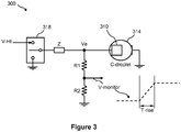
- FIG. 3 illustrates another nonlimiting example of a capacitance detection circuit 300 for determining the capacitance of a droplet within a droplet actuator.
- capacitance detection circuit 300 performs a passive capacitance measurement by monitoring the charge time of capacitance C-droplet.
- capacitance detection circuit 300 includes a transport electrode 310 upon which may be disposed a droplet 314, which may be grounded. When droplet 314 is fully or partially present it has a capacitance C-droplet.
- the control line of transport electrode 310 has a certain impedance Z and may be connected to either a bias voltage V-HI or to ground via a switch 318. Switch 318 may be any electronic switch mechanism.
- An electrode voltage Ve which may be a high voltage
- at transport electrode 310 may be monitored by use of a voltage divider circuit, in order to provide a low voltage monitor.
- a resistor R1 and R2 are arranged in series between electrode voltage Ve and ground, and a voltage V-monitor is provided at a node between resistors R1 and R2.
- a rise time T-rise of voltage V-monitor when transport electrode 310 is switched from ground to bias voltage V-HI may be monitored.
- the capacitance C-droplet that is introduced causes the rise time T-rise of voltage V-monitor to increase.
- the change in T-rise which is the result of introducing capacitance C-droplet, may be measurable by, for example, an analog-to-digital (A/D) converter (not shown) that is connected to voltage V-monitor.
- A/D analog-to-digital
- the change in T-rise at voltage V-monitor is proportional to the amount of capacitance C-droplet, i.e., T-rise increases as capacitance C-droplet increases.
- a capacitance C-droplet value may be determined, which may be correlated to the absence, presence, and/or partial presence of, for example, droplet 314 at transport electrode 310.
- FIG. 4 illustrates yet another nonlimiting example of a capacitance detection circuit 400 for determining the capacitance of a droplet within a droplet actuator.
- capacitance detection circuit 400 performs a passive capacitance measurement by monitoring the discharge time of capacitance C-droplet.
- capacitance detection circuit 400 is substantially the same as capacitance detection circuit 300 of Figure 3 except that it does not include a voltage divider circuit. Instead, electrode voltage Ve of capacitance detection circuit 400 is monitored directly via a charge integrating amplifier 410, which outputs a voltage V-out that is the integral of its input voltage.
- the elements of capacitance detection circuit 300 and capacitance detection circuit 400 may be combined.
- Transport electrode 310 is first connected to bias voltage V-HI via switch 318 for a period of time that allows capacitance C-droplet to be fully charged to a certain voltage. After capacitance C-droplet is fully charged, transport electrode 310 is then connected to ground via switch 318, which discharges capacitance C-droplet and, thus, electrode voltage Ve falls from the certain voltage to ground with a fall time of T-fall. Consequently, when droplet 314 is fully or partially present at transport electrode 310, the capacitance C-droplet that is introduced causes the fall time T-fall of electrode voltage Ve to increase.
- the integral of T-fall may be analyzed at V-out of charge integrating amplifier 410 by, for example, an A/D converter (not shown).
- the change in T-fall of electrode voltage Ve is proportional to the amount of capacitance C-droplet, i.e., T-fall increases as capacitance C-droplet increases.
- a capacitance C-droplet value may be determined, which may be correlated to the absence, presence, and/or partial presence of, for example, droplet 314 at transport electrode 310.
- Capacitance detection in a droplet actuator can be employed to affect a variety of useful results. Examples follow.
- Figures 5A, 5B, 5C, and 5D illustrate a nonlimiting example of using capacitance detection in a droplet actuator. More specifically, Figures 5A, 5B, 5C, and 5D illustrate a set of nonlimiting exemplary steps of a droplet operation process 500, which demonstrates a simple inexpensive analysis of basic microfluidic functions by use of capacitance detection. In particular, Figures 5A, 5B, 5C, and 5D show the real-time progression of an exemplary droplet 514 moving along a line of transport electrodes 510, such as transport electrodes 510a, 510b, and 510c.
- transport electrodes 510 such as transport electrodes 510a, 510b, and 510c.
- each of transport electrodes 510a, 510b, and 510c are connected to a capacitance detection mechanism, such as, but not limited to, capacitance detection circuit 200 of Figure 2 , capacitance detection circuit 300 of Figure 3 , and capacitance detection circuit 400 of Figure 4 , for measuring the capacitance C-droplet.
- a capacitance detection mechanism such as, but not limited to, capacitance detection circuit 200 of Figure 2 , capacitance detection circuit 300 of Figure 3 , and capacitance detection circuit 400 of Figure 4 , for measuring the capacitance C-droplet.
- the absence, presence, partial presence, and/or location of droplet 514 along the line of transport electrodes 510 may be determined in real time.
- a bar graph of the relative capacitance C-droplet at each of transport electrodes 510a, 510b, and 510c is provided.
- Figure 5A shows droplet 514 at a first location along the line of transport electrodes 510a, 510b, and 510c. More specifically, droplet 514 is centered upon transport electrode 510a and shows that the footprint area of droplet 514 is larger than the area of transport electrode 510a. Therefore, while droplet 514 is centered upon transport electrode 510a, it also overlaps slightly the adjacent transport electrode 510b.
- the bar graph for Figure 5A of the relative amount of capacitance C-droplet shows that maximum capacitance C-droplet is detected at transport electrode 510a, a small capacitance C-droplet is detected at transport electrode 510b, and no capacitance C-droplet is detected at transport electrode 510c. As a result, without the need for visualization, it may be concluded that the location of droplet 514 is substantially at transport electrode 510a.
- Figure 5B shows droplet 514 at a second location along the line of transport electrodes 510a, 510b, and 510c. More specifically, droplet 514 is bridging transport electrodes 510a and 510b. Therefore, a substantially equal portion of droplet 514 is upon each of transport electrodes 510a and 510b.
- the bar graph for Figure 5B of the relative amount of capacitance C-droplet shows that approximately half the maximum capacitance C- droplet is detected at each of transport electrodes 510a and 510b and no capacitance C- droplet is detected at transport electrode 510c. As a result, without the need for visualization, it may be concluded that the movement of droplet 514 from transport electrode 510a to 510b is progressing as expected.
- Figure 5C shows droplet 514 at a third location along the line of transport electrodes 510a, 510b, and 510c. More specifically, droplet 514 is centered upon transport electrode 510b and shows that the footprint area of droplet 514 is larger than the area of transport electrode 510b. Therefore, while droplet 514 is centered upon transport electrode 510b, it also overlaps slightly the adjacent transport electrodes 510a and 510c.
- the bar graph for Figure 5C of the relative amount of capacitance C-droplet shows that a small amount of capacitance C-droplet is detected at transport electrode 510a, maximum capacitance C- droplet is detected at transport electrode 510b, and a small amount of capacitance C- droplet is detected at transport electrode 510c. As a result, without the need for visualization, it may be concluded that the movement of droplet 514 to substantially the position of transport electrode 510b has occurred as expected.
- Figure 5D shows droplet 514 at a fourth location along the line of transport electrodes 510a, 510b, and 510c. More specifically, droplet 514 is bridging transport electrodes 510b and 510c. Therefore, a substantially equal portion of droplet 514 is upon each of transport electrodes 510b and 510c.
- the bar graph for Figure 5D of the relative amount of capacitance C-droplet shows that no capacitance C-droplet is detected at transport electrode 510a and approximately half the maximum capacitance C-droplet is detected at each of transport electrodes 510b and 510c. As a result, without the need for visualization, it may be concluded that the movement of droplet 514 from transport electrode 510b to 510c is progressing as expected.
- Figures 6A and 6B illustrate another nonlimiting example of using capacitance detection in a droplet actuator. More specifically, Figures 6A and 6B illustrate a nonlimiting example of a droplet actuator 600 that uses capacitance detection in a droplet splitting operation for determining droplet uniformity. In particular, Figure 6A shows the droplet splitting operation in progress and Figure 6B shows the droplet splitting operation when complete.
- Droplet actuator 600 includes a reservoir electrode 610 that outlets to a line of transport electrodes 614a, 614b, and 614c. Adjacent to and on either side of transport electrode 614c is a transport electrode 618a and 618b.
- each of transport electrodes 614a, 614b, 614c, 618a and 618b are connected to a capacitance detection mechanism, such as, but not limited to, capacitance detection circuit 200 of Figure 2 , capacitance detection circuit 300 of Figure 3 , and capacitance detection circuit 400 of Figure 4 , for detecting the capacitance C-droplet.
- a capacitance detection mechanism such as, but not limited to, capacitance detection circuit 200 of Figure 2 , capacitance detection circuit 300 of Figure 3 , and capacitance detection circuit 400 of Figure 4 , for detecting the capacitance C-droplet.
- a volume of fluid 622 is provided at reservoir electrode 610.
- transport electrode 614c is activated and fluid 622 from reservoir electrode 610 is pinched off across a split zone 626 along transport electrodes 614a and 614b to form a droplet 630 at transport electrode 614c.
- the size of droplet 630 may vary, for example, because as the volume of fluid 622 at reservoir electrode 610 varies, the amount of fluid pinched off may vary.
- capacitance detection may be used in order to monitor the droplet splitting operation and provide uniform droplet dispensing.
- the relative position and distribution of the liquid across each electrode may be determined.
- the progression of fluid 622 as it flows across portions of transport electrode 614a, transport electrode 614b, transport electrode 614c, transport electrode 618a and transport electrode 618b may be monitored in real-time.
- transport electrode 614a and transport electrode 614b are deactivated, the progression of the fluid as it drains back to reservoir electrode 610 can similarly be determined.
- the size of droplet 630 may be determined and adjustments to the process may be performed in order to ensure a reproducible droplet geometry at transport electrode 614c.
- the volume of fluid at reservoir electrode 610 and at split zone 626 may be determined and adjustments to the process may be performed in order to ensure a reproducible droplet geometry at transport electrode 614c. For example, if droplet 630 is too small, certain actions or adjustments to the droplet operation process may be performed, such as, but not limited to, returning the droplet to the reservoir, adding more volume to reservoir, adjusting the electrode bias voltage, adjusting the electrode bias time, and any combinations thereof. Adjustments may also be made in real-time as the droplet splitting process in being performed based on capacitance-based feedback from each of the electrodes participating in the process. For example, the amount of voltage on a particular electrode could be adjusted to maintain a particular rate of liquid drainage or certain electrodes could activated or deactivated at particular times depending on the location of the liquid and progression of the droplet splitting process.
- Figure 7 illustrates yet another nonlimiting example of using capacitance detection in a droplet actuator. More specifically, Figure 7 illustrates a nonlimiting example of a droplet actuator 700 that uses capacitance detection in a droplet transport fault detection application and/or a quality control application.
- Droplet actuator 700 includes a set of transport electrodes that are arranged, for example, in a grid.
- droplet actuator 700 includes an array of transport electrodes 710 that are arranged along rows A through G and columns 1 through 11 and that are in fluid connection with a reservoir 714 and multiple receptacles 718, such as receptacles 718a through 718f.
- all or certain selected transport electrodes 710 are connected to a capacitance detection mechanism, such as, but not limited to, capacitance detection circuit 200 of Figure 2 , capacitance detection circuit 300 of Figure 3 , and capacitance detection circuit 400 of Figure 4 , for detecting the droplet capacitance C-droplet.
- a capacitance detection mechanism such as, but not limited to, capacitance detection circuit 200 of Figure 2 , capacitance detection circuit 300 of Figure 3 , and capacitance detection circuit 400 of Figure 4 , for detecting the droplet capacitance C-droplet.
- capacitance detection may be used for determining whether an electrode has failed (e.g., due to open electrical connection). More specifically, capacitance detection may be used to monitor the flow within droplet actuator 700.
- Figure 7 shows a droplet 722 moving from, for example, grid location B2 to B7. If the expected change in capacitance is not measured at a certain selected transport electrode 710 along the path, a fault is detected, which may prompt certain action, such as, but not limited to, routing droplet 722 from grid location B2 to B7 via an alternate path.
- droplet 722 may be alternatively routed from grid location B2 to C2, then from C2 to C7, then from C7 to B7.
- FIG. 7 shows an air bubble 726 that is trapped within droplet actuator 700 near one or more transport electrodes 710, which is problematic. Analyzing the capacitance profile of each transport electrode 710 in oil may provide an indication of whether an air bubble is present and its position and extent within the droplet actuator. When a bubble is detected, the device may be reloaded with oil to remedy the problem.
- a droplet actuator such as droplet actuator 700
- a conductive fluid such as water.
- the capacitance profile of each transport electrode 710 in a conductive fluid may be analyzed in order to determine whether the capacitance profile for each transport electrode 710 matches an expected capacitance profile. In this way, an open transport electrode 710 or a shorted transport electrode 710 may be detected.
- Capacitance detection of the presence, absence or partial presence of a droplet at the position of a particular electrode may be used as a basis for measuring the speed of droplet transport in a droplet actuator. Position measurements made at different points in time can be used to calculate the average velocity of droplet motion in a particular interval. For example, a signal may be sent to activate an electrode adjacent to a droplet and the time required for the droplet to move onto that activated electrode may be determined by monitoring the capacitance at that electrode over time due to the footprint of the droplet. Certain threshold levels of capacitance may be defined to facilitate measurements of this type. For example, one could define a transport time based on the time required for the capacitance to change from 10% to 90% where 0% represents the minimum footprint value and 100% represents the maximum footprint value.
- the measurement need not be made on the activated receiving electrode, but could be made on the deactivated source electrode (i.e. the rate at which the droplet moves away from the source is determined) or could made using a third electrode. For example, the time required for the droplet to traverse an activated electrode and to overlap the next adjacent electrode to a could be measured.
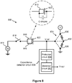
- FIG. 8 illustrates a schematic diagram of an embodiment of a droplet actuation circuit 800 of the invention.
- Droplet actuation circuit 800 includes a capacitance detection circuit and may be used for performing a capacitance measurement at any electrode of a droplet actuator, e.g., for performing droplet detection.
- Droplet actuation circuit 800 may include an electrode 810, e.g., droplet actuation electrode, for performing droplet operations.
- Electrode 810 is electrically connected to a high-voltage supply 814, e.g., at an electrowetting voltage, via an electronic switch 818.
- Electronic switch 818 may be the droplet actuation switch for connecting/disconnecting the voltage of high-voltage supply 814 to/from electrode 810.
- Electrode 810, high-voltage supply 814, and electronic switch 818 may in some embodiments be associated with the bottom plate (not shown) of a droplet actuator (not shown). Additionally, the droplet actuator may have arrays and/or paths of electrodes 810 for performing droplet operations.
- Figure 9 illustrated hereinbelow, illustrates additional details of a droplet actuation circuit that includes multiple electrodes.
- Droplet actuation circuit 800 further includes a reference electrode 822 that may be electrically connected to multiple nodes via an electronic switch.
- reference electrode 822 may be electrically connected to a ground node 826, a voltage node 830, or a high-impedance node 832 via an electronic switch 834, e.g., a 10 position electronic switch.
- Reference electrode 822, ground node 826, voltage node 830, high-impedance node 832, and electronic switch 834 may in some embodiments be associated with the top plate (not shown) of a droplet actuator.
- reference electrode 822 When reference electrode 822 is electrically connected to ground node 826, it serves as a ground reference plane for the droplet actuator.
- reference electrode 822 When reference electrode 822 is electrically connected to voltage node 830, it serves as a voltage reference plane for the droplet actuator. When reference electrode 822 is electrically connected to high-impedance node 832, it is substantially disconnected from ground node 826 and voltage node 830 and is, thus, considered in a "float" state.
- the invention provides a capacitance detection circuit 836 that includes a protection circuit 838 and a detection circuit 842. More specifically, a voltage, V-ref, at reference electrode 822 is electrically connected to an input of protection circuit 838 of capacitance detection circuit 836. An output of protection circuit 838 is electrically connected to an input of detection circuit 842 of capacitance detection circuit 836. An output voltage, V-out, of detection circuit 842 is provided for monitoring by external resources (not shown). Protection circuit 838 is provided to protect detection circuit 842 from damage due to high voltage when electronic switch 834 is connected to voltage node 830.
- Figure 8 also shows that when a droplet 846 is present at electrode 810, the droplet 846 has a certain capacitance, C-droplet, between electrode 810 and reference electrode 822. By contrast, when droplet 846 is not present at electrode 810, capacitance, C-droplet, does not exist between electrode 810 and reference electrode 822.
- reference electrode 822 may be electrically connected, for example, to ground node 826 via electronic switch 834 and droplet operations may occur at electrode 810 under the control of electronic switch 818.
- reference electrode 822 is electrically connected to high-impedance node 832 via electronic switch 834, to place reference electrode 822 in a "float" state.
- electronic switch 818 that is associated with electrode 810 serves as a rising edge generator. More specifically, a rising edge at electrode 810 is generated by toggling electronic switch 818 from an open state to a closed state, thereby causing a voltage transition to occur at electrode 810 from about 0 volts to about the value of high-voltage supply 814.
- the capacitive energy that is caused by the presence of capacitance, C-droplet, of droplet 846 at electrode 810 is coupled to reference electrode 822, which then is coupled to protection circuit 838 and passed to detection circuit 842 of capacitance detection circuit 836.
- This capacitive energy generated is a voltage pulse at V-ref that is proportional to the capacitance, C- droplet.
- the voltage pulse that is present at the V-ref node which may be a high voltage pulse, is processed via protection circuit 838 and detection circuit 842 of capacitance detection circuit 836 to provide a digital V-out value that reflects the magnitude of capacitance, C- droplet.
- a digital V-out value that reflects the magnitude of capacitance, C- droplet.
- the digital V-out value of detection circuit 842 is about 0 volts, this indicates that there is no droplet 846 present at electrode 810.
- the digital V-out value of detection circuit 842 is a certain expected value that is greater than about 0 volts, this indicates that droplet 846 is present at electrode 810.
- capacitance detection circuit 836 provides a way to detect the presence or absence of a droplet at a certain electrode by detecting the presence or absence of capacitance, C-droplet.
- Figures 10A and 10B illustrated hereinbelow, illustrate more details of an example capacitance detection circuit that includes a detection circuit and a protection circuit.
- FIG. 9 illustrates a schematic diagram of an embodiment of a droplet actuation circuit 900 that includes a capacitance detection circuit.
- the capacitance detection circuit may, for example, be used for a capacitance measurement at any electrode of a droplet actuator, e.g., for performing droplet detection.
- Droplet actuator circuit 900 is substantially the same as droplet actuator circuit 800 of Figure 8 , except for the illustration of multiple electrodes 810 and the associated bank of electronic switches 818.
- Figure 9 shows that all electronic switches 818 are connected to a common high voltage of high-voltage supply 814.
- a rising edge may be generated by activating the electronic switch 818 that is associated with an electrode 810 of interest and capacitance detection circuit 836 may be used to detect the presence or absence of capacitance, C-droplet, at the electrode 810 of interest.
- a sequential operation may occur, i.e., sequencing from one electrode 810/electronic switch 818 pair to the next, by which capacitance detection takes place from one electrode 810 to the next.
- FIG 10A illustrates a schematic diagram of an embodiment of a capacitance detection circuit, such as capacitance detection circuit 836, of the invention that may be used in a droplet actuator for the purpose of performing droplet detection.
- Capacitance detection circuit 836 includes protection circuit 838 and detection circuit 842. More specifically, the input of protection circuit 838 is fed, for example, by voltage V-ref of droplet actuator circuit 800 or 900 of Figure 8 or 9 , respectively. The output of protection circuit 838 feeds the input of detection circuit 842, which provides a digital V-out value.
- protection circuit 838 of capacitance detection circuit 836 includes a voltage divider network, such as a resistor R1 and R2 that are electrically connected in series, as shown in Figure 10A .
- a voltage node A between resistor R1 and R2 is electrically connected to one side of a capacitor C1.
- the opposite side of capacitor C1 is electrically connected to the input of detection circuit 842. Because of the action of the voltage divider network, which is formed by resistors R1 and R2, a fraction of the voltage value of V-ref is present at voltage node A.
- resistors R1 and R2 are such that a suitably safe, low-voltage at node A feeds the input of detection circuit 842, to ensure that a high voltage at V-ref does not damage the components of detection circuit 842. Additionally, capacitor C1 provides an alternating current (AC) coupling mechanism for coupling the AC components only of V-ref to detection circuit 842.
- AC alternating current
- detection circuit 842 of capacitance detection circuit 836 includes an amplifier 1010, a charge integrating amplifier 1014, and an analog-to-digital (A/D) converter 1018, which are electrically connected as shown in Figure 10A .
- Amplifier 1010 may, for example, be a conventional operational amplifier device that scales its input voltage either up or down to any suitable voltage for feeding the next signal processing stage, the charge integrating amplifier 1014.
- amplifier 1010 may serve as a buffer only, to convert the input signal impedance to a certain impedance value that is suited to pass to the next signal processing stage, charge integrating amplifier 1014.
- Charge integrating amplifier 1014 may, for example, be a conventional charge integrating amplifier that generates an output voltage (e.g., voltage node C) that is the integral of its input voltage (e.g., voltage node B), which is illustrated in Figure 10B .
- a reason for integrating the output of amplifier 1010 is to render the signal less sensitive to stray capacitances that may be present at electrode 810, while still capturing the capacitance across droplet 846.
- A/D converter 1018 may, for example, be a conventional n-bit A/D converter device for converting an analog input voltage to an n-bit digital word.
- A/D converter 1018 may be an 8-bit, 10-bit, or 16-bit A/D converter, depending on a desired resolution.
- Reference electrode 822 is electrically connected to high-impedance node 832 via electronic switch 834, to place reference electrode 822 in a "float" state, which provides electrical isolation from ground node 826 and voltage node 830 via a high resistance (e.g., Megaohms).
- a high resistance e.g. Megaohms
- Protection circuit 838 of capacitance detection circuit 836 reduces the amplitude of V-ref to a suitably low voltage via resistors R1 and R2.
- Capacitor C1 then couples the low-voltage pulse at node A to amplifier 1010, which scales the low-voltage pulse to any usable value for feeding charge integrating amplifier 1014.
- Charge integrating amplifier 1014 generates an output voltage (e.g., voltage node C) that is the integral of its input voltage (e.g., voltage node B), as shown in Figure 10B .
- A/D converter 1018 performs an analog-to-digital conversion of the output of charge integrating amplifier 1014.
- A/D converter 1018 may be sampled, for example, at some time after time t1 (see Figure 10B ) and its digital V-out value is captured by an external processor (not shown) for analysis.
- A/D converter 1018 may be sampled once only at some time after time t1 (see Figure 10B ) to arrive at a measurement of capacitance, C-droplet.
- A/D converter 1018 may be sampled multiple times after time t1 and then the multiple digital V-out values may be averaged to arrive at a measurement of capacitance, C-droplet.
- a capacitance detection circuit of the invention may be used for validating one or more droplet operations on a droplet actuator.
- the circuit may be used to verify whether one or more droplet operations in a certain protocol have been achieved.
- a capacitance detection operation may occur after each movement to verify that the droplet has moved as expected.
- a capacitance detection circuit such as capacitance detection circuit 836, may be used for performing a droplet actuator characterization operation. For example, a droplet may be moved along a line of electrodes toward a designated detection location at a certain droplet actuation frequency. At the end of the sequence, a capacitance detection operation may occur at the designated detection location, to verify that the droplet arrived successfully. This sequence may be repeated at higher and higher droplet actuation frequencies until the droplet actuator fails. In performing this characterization operation using the capacitance detection circuit of the invention, the droplet actuation frequency specification of the droplet actuator may be established.
- the droplet is a sample fluid, such as a biological sample, such as whole blood, lymphatic fluid, serum, plasma, sweat, tear, saliva, sputum, cerebrospinal fluid, amniotic fluid, seminal fluid, vaginal excretion, serous fluid, synovial fluid, pericardial fluid, peritoneal fluid, pleural fluid, transudates, exudates, cystic fluid, bile, urine, gastric fluid, intestinal fluid, fecal samples, fluidized tissues, fluidized organisms, biological swabs and biological washes.
- a biological sample such as whole blood, lymphatic fluid, serum, plasma, sweat, tear, saliva, sputum, cerebrospinal fluid, amniotic fluid, seminal fluid, vaginal excretion, serous fluid, synovial fluid, pericardial fluid, peritoneal fluid, pleural fluid, transudates, exudates, cystic fluid, bile, urine, gastric fluid, intestinal fluid, f
- the fluid that includes a reagent such as water, deionized water, saline solutions, acidic solutions, basic solutions, detergent solutions and/or buffers.
- the fluid includes a reagent, such as a reagent for a biochemical protocol, such as a nucleic acid amplification protocol, an affinity -based assay protocol, a sequencing protocol, and/or a protocol for analyses of biological fluids.
- the gap is typically filled with a filler fluid.
- the filler fluid may, for example, be a low-viscosity oil, such as silicone oil.
- Other examples of filler fluids are provided in WO 2007/120,421 .
- One approach for providing capacitance detection in a droplet actuator may include, but is not limited to, the steps of providing a mechanism for monitoring the electrode voltage Ve, switching on the electrode voltage Ve and measuring its rise time with no conductive droplet present at a transport electrode of interest, switching off the electrode voltage Ve, providing a conductive droplet at the transport electrode of interest in order to introduce capacitance C-droplet, switching on the electrode voltage Ve and measuring its rise time with conductive droplet present at the transport electrode of interest, calculating the difference between the two rise time measurements, correlating the difference between the two rise time measurements with a capacitance value, and correlating the capacitance value with a droplet footprint area.
- Capacitance detection in general, is particularly suited for most electrowetting applications given the typical physical spacing between electrodes. Moreover, capacitance detection provides a more direct correlation between bead and/or droplet properties than does the measurement of other electrical quantities, such as inductance and impedance. Such other properties typically require additional processing for reactance, time constants and electron propagation factors, among other considerations. In that sense, embodiments determining capacitance require relatively less processing and hardware equipment, while delivering simpler and more accurate calculations than do measurements of other properties. In any case, one skilled in the art will appreciate that preferred embodiments described herein are merely exemplary, and other embodiments consistent with the underlying principles of the present invention may measure capacitance in a number of other manners known in the industry. Furthermore, while various exemplary embodiments are described herein with reference to capacitance, it is understood that other methods can be performed using other types of impedance circuits, such as resistance.
Claims (15)
- Ein Tröpfchenaktuator zum Manipulieren eines Fluids unter Verwendung eines elektrischen Feldes, beinhaltend:(a) eine Aktuatorelektrode (114, 810), die konfiguriert ist, das elektrische Feld auf das Fluid (846) zu übertragen;(b) eine Bezugselektrode (122, 822) in Kommunikation mit der Aktuatorelektrode (114, 810);(c) einen Kapazitätsdetektionsschaltkreis (836) in Kommunikation mit der Bezugselektrode (122, 822), der konfiguriert ist, eine Kapazität des Fluids (130, 846) zu detektieren; und(d) einen Prozessor in Kommunikation mit dem Kapazitätsdetektionsschaltkreis (836), der konfiguriert ist, auf der Basis der detektierten Kapazität des Fluids (130, 846) eine Position des Fluids (130, 846) zu bestimmen; gekennzeichnet durch:einen ersten elektronischen Schalter (818) zum selektiven Verbinden der Aktuatorelektrode (114, 810) mit einer Hochspannungsversorgung (814);einen Erdungsknoten (826), einen Hochspannungsknoten (830) und einen Hochimpedanzknoten (832), der ein Zwischenpotenzial aufweist; undeinen zweiten elektronischen Schalter (834) zum selektiven Verbinden der Bezugselektrode (122, 822) mit einem von dem Erdungsknoten (826), dem Hochspannungsknoten (830) und dem Hochimpedanzknoten (832).
- Tröpfchenaktuator gemäß Anspruch 1, wobei die Aktuatorelektrode (114, 810) konfiguriert ist, Tröpfchenoperationen durch ein Mittel, das Elektrobenetzung beinhaltet, herbeizuführen.
- Tröpfchenaktuator gemäß Anspruch 1, der ferner eine Vielzahl von Aktuatorelektroden (114, 810) in Kommunikation mit der Bezugselektrode (122, 822) beinhaltet.
- Tröpfchenaktuator gemäß Anspruch 3, wobei die Vielzahl von Aktuatorelektroden (114, 810) sequenziell mit der Bezugselektrode (122, 822) kommuniziert.
- Tröpfchenaktuator gemäß Anspruch 1, der ferner ein erstes und zweites Substrat (110, 126) beinhaltet, die durch das Fluid (130, 846) getrennt sind, wobei das erste Substrat (110) die Aktuatorelektrode (114, 810) beinhaltet und das zweite Substrat (126) die Bezugselektrode (122, 822) beinhaltet.
- Tröpfchenaktuator gemäß Anspruch 5, wobei das Fluid (130, 846) ein Tröpfchen beinhaltet und das Tröpfchen über der Aktuatorelektrode (114, 810) angeordnet ist, und wobei der Prozessor ferner konfiguriert ist, eine Messung einer Menge, um die ein Anteil des Tröpfchens die Aktuatorelektrode (114, 810) überlappt, zu initiieren.
- Tröpfchenaktuator gemäß Anspruch 5, wobei das erste Substrat (110) eine Vielzahl von Aktuatorelektroden (114, 810) beinhaltet und jede Aktuatorelektrode (114, 810) den gleichen Abstand von der Bezugselektrode (122, 822) aufweist.
- Tröpfchenaktuator gemäß Anspruch 7, wobei das erste Substrat (110) ein Gitter oder ein Array von Aktuatorelektroden (114, 810) beinhaltet und das zweite Substrat (126) eine einzelne Bezugselektrode (122, 822) beinhaltet, die sich im Wesentlichen im gleichen Abstand von jeder der Aktuatorelektroden (114, 810) befindet, wobei die Messung an jeder der Aktuatorelektroden (114, 810) in dem Gitter oder Array auf der Basis der einzelnen Bezugselektrode (122, 822) bestimmt werden kann.
- Ein Verfahren zum Verwenden eines Tröpfchenaktuators gemäß einem der vorhergehenden Ansprüche, zum Bestimmen, Quantifizieren, Schätzen oder Beurteilen einer Eigenschaft eines Tröpfchens, wobei das Verfahren Folgendes beinhaltet:(a) Bereitstellen eines Tröpfchens auf einer Aktuatorelektrode (114, 810) des Tröpfchenaktuators;(b) Bestimmen der Kapazität an der Aktuatorelektrode (114, 810);(c) Vergleichen der Kapazität mit einer mit der Eigenschaft assoziierten erwarteten Kapazität; und(d) Bestimmen, Quantifizieren, Schätzen oder Beurteilen der Eigenschaft auf der Basis des Vergleichs;wobei die Eigenschaft eine der Folgenden beinhaltet:- das Vorhandensein, partielle Vorhandensein oder die Abwesenheit des Tröpfchens an der Aktuatorelektrode (114, 810),- ob das Tröpfchen ein oder mehrere Kügelchen beinhaltet;- ob das Tröpfchen eine oder mehrere biologische Zellen beinhaltet;- eine Quantität von Kügelchen in dem Tröpfchen;- Zellen in dem Tröpfchen;- Lebensfähigkeit von Zellen in dem Tröpfchen;- Apoptose von Zellen in dem Tröpfchen;- Identität eines Kügelchentyps in dem Tröpfchen.
- Ein Verfahren zum Bereitstellen eines Teiltröpfchens von einem Tröpfchen auf einem Tröpfchenaktuator gemäß einem der Ansprüche 1 bis 8, wobei das Verfahren Folgendes beinhaltet: Bestimmen der Lage eines oder mehrerer Anteile des Tröpfchens während einer Teilungs- oder Ausgabetröpfchenoperation durch Detektieren der Kapazität an einer oder mehreren Aktuatorelektroden (114, 810) auf dem Tröpfchenaktuator und Anpassen eines oder mehrerer Parameter der Teilungs- oder Ausgabeoperation zum Beeinflussen des Volumens des Teiltröpfchens.
- Verfahren gemäß Anspruch 10, wobei der Tröpfchenaktuator Folgendes umfasst:ein erstes Substrat (110), das eine Vielzahl von Aktuatorelektroden (114, 810) beinhaltet, die auf dem ersten Substrat (110) eingerichtet sind, zum Bilden des Teiltröpfchens von dem Tröpfchen auf einer Oberfläche des Substrats (110);wobei das Verfahren Folgendes beinhaltet:(a) Aktivieren einer oder mehrerer der Aktuatorelektroden (114, 810) zum Verlängern eines Anteils des Tröpfchens oder des ganzen Tröpfchens während der Verwendung des Kapazitätsdetektionsschaltkreises zum Bestimmen der Lage eines oder mehrerer Anteile des Tröpfchens; und(b) wenn die Lage eines oder mehrere Anteile des Tröpfchens eine vorgegebene Position erreicht, wie durch den Kapazitätsdetektionsschaltkreis bestimmt, Deaktivieren einer mittleren der einen oder mehreren Aktuatorelektroden (114, 810) entlang dem verlängerten Tröpfchen, um das Teiltröpfchen zu bilden.
- Ein Verfahren zum Detektieren von Fluid innerhalb eines Tröpfchenaktuators gemäß einem der Ansprüche 1 bis 8, der eine Vielzahl von Aktuatorelektroden (114, 810) aufweist, die jeweils konfiguriert sind, ein elektrisches Feld auf das Fluid zu übertragen, wobei das Verfahren Folgendes beinhaltet:(a) Abtasten einer Kapazität des Fluids an einer Aktuatorelektrode (114, 810) der Vielzahl von Aktuatorelektroden (114, 810); und(b) Bestimmen, dass das Fluid an der Aktuatorelektrode (114, 810) vorhanden ist, unter Verwendung der abgetasteten Kapazität.
- Ein Verfahren zum Bestimmen der Überlappung eines Fluidtröpfchens in einem Tröpfchenaktuator gemäß einem der Ansprüche 1 bis 8, wobei das Verfahren Folgendes beinhaltet:(a) Anordnen eines Fluidtröpfchens über der Aktuatorelektrode (114, 810); und(b) Initiieren einer Prozessormessung einer Menge, um die ein Anteil des Tröpfchens die Aktuatorelektrode (114, 810) überlappt.
- Ein Verfahren zum Bestimmen des Vorhandenseins von Luftblasen in einem Tröpfchenaktuator gemäß einem der Ansprüche 1 bis 8, wobei das Verfahren Folgendes beinhaltet:(a) Versuchen des Füllens eines Anteils des Tröpfchenaktuators mit einem Füllerfluid, um einen gefüllten Anteil des Tröpfchenaktuators bereitzustellen;(b) Testen der Kapazität an Aktuatorelektroden (114, 810) in dem gefüllten Anteil des Tröpfchenaktuators; und(c) Identifizieren des Vorhandenseins von einer oder mehreren Luftblasen auf der Basis einer Kapazität an einer oder mehreren der Aktuatorelektroden (114, 810), die sich von der erwarteten Kapazität an der Aktuatorelektrode (114, 810) bei Vorhandensein des Füllerfluids unterscheidet.
- Ein Verfahren zum Testen von Aktuatorelektroden auf einem Tröpfchenaktuator gemäß einem der Ansprüche 1 bis 8, wobei das Verfahren Folgendes beinhaltet:(a) Füllen mindestens eines Anteils des Tröpfchenaktuators mit einem Fluid, das eine bekannte Kapazität aufweist, um einen gefüllten Anteil des Tröpfchenaktuators bereitzustellen;(b) Testen der Kapazität an Aktuatorelektroden (114, 810) in dem gefüllten Anteil des Tröpfchenaktuators; und(c) Identifizieren fehlerhafter Aktuatorelektroden (114, 810) auf der Basis einer Kapazität, die sich von der erwarteten Kapazität an der Aktuatorelektrode (114, 810) bei Vorhandensein des Fluids unterscheidet.
Applications Claiming Priority (4)
| Application Number | Priority Date | Filing Date | Title |
|---|---|---|---|
| US88996607P | 2007-02-15 | 2007-02-15 | |
| US98074607P | 2007-10-17 | 2007-10-17 | |
| US98052007P | 2007-10-17 | 2007-10-17 | |
| PCT/US2008/054134 WO2008101194A2 (en) | 2007-02-15 | 2008-02-15 | Capacitance detection in a droplet actuator |
Publications (3)
| Publication Number | Publication Date |
|---|---|
| EP2109774A2 EP2109774A2 (de) | 2009-10-21 |
| EP2109774A4 EP2109774A4 (de) | 2014-11-12 |
| EP2109774B1 true EP2109774B1 (de) | 2018-07-04 |
Family
ID=39690825
Family Applications (1)
| Application Number | Title | Priority Date | Filing Date |
|---|---|---|---|
| EP08730019.0A Active EP2109774B1 (de) | 2007-02-15 | 2008-02-15 | Kapazitätserkennung in einem tröpfchenaktuator |
Country Status (3)
| Country | Link |
|---|---|
| US (3) | US8872527B2 (de) |
| EP (1) | EP2109774B1 (de) |
| WO (1) | WO2008101194A2 (de) |
Families Citing this family (122)
| Publication number | Priority date | Publication date | Assignee | Title |
|---|---|---|---|---|
| PL1859330T3 (pl) | 2005-01-28 | 2013-01-31 | Univ Duke | Urządzenia i sposoby manipulacji kropelkami na płytkach obwodów drukowanych |
| US20140193807A1 (en) | 2006-04-18 | 2014-07-10 | Advanced Liquid Logic, Inc. | Bead manipulation techniques |
| US8658111B2 (en) * | 2006-04-18 | 2014-02-25 | Advanced Liquid Logic, Inc. | Droplet actuators, modified fluids and methods |
| US7439014B2 (en) | 2006-04-18 | 2008-10-21 | Advanced Liquid Logic, Inc. | Droplet-based surface modification and washing |
| US8637324B2 (en) | 2006-04-18 | 2014-01-28 | Advanced Liquid Logic, Inc. | Bead incubation and washing on a droplet actuator |
| US8716015B2 (en) | 2006-04-18 | 2014-05-06 | Advanced Liquid Logic, Inc. | Manipulation of cells on a droplet actuator |
| US20150107995A1 (en) * | 2006-04-18 | 2015-04-23 | Advanced Liquid Logic, Inc. | Droplet Actuator Devices and Methods for Manipulating Beads |
| US10078078B2 (en) | 2006-04-18 | 2018-09-18 | Advanced Liquid Logic, Inc. | Bead incubation and washing on a droplet actuator |
| US8809068B2 (en) | 2006-04-18 | 2014-08-19 | Advanced Liquid Logic, Inc. | Manipulation of beads in droplets and methods for manipulating droplets |
| WO2009111769A2 (en) | 2008-03-07 | 2009-09-11 | Advanced Liquid Logic, Inc. | Reagent and sample preparation and loading on a fluidic device |
| US8685344B2 (en) | 2007-01-22 | 2014-04-01 | Advanced Liquid Logic, Inc. | Surface assisted fluid loading and droplet dispensing |
| CA2712863C (en) | 2007-02-09 | 2015-01-06 | Advanced Liquid Logic, Inc. | Droplet actuator devices and methods employing magnetic beads |
| EP2109774B1 (de) | 2007-02-15 | 2018-07-04 | Advanced Liquid Logic, Inc. | Kapazitätserkennung in einem tröpfchenaktuator |
| EP2837692A1 (de) | 2007-03-22 | 2015-02-18 | Advanced Liquid Logic, Inc. | Enzymassays für einen Tropfenaktuator |
| WO2011084703A2 (en) | 2009-12-21 | 2011-07-14 | Advanced Liquid Logic, Inc. | Enzyme assays on a droplet actuator |
| AU2008237017B2 (en) * | 2007-04-10 | 2013-10-24 | Advanced Liquid Logic, Inc. | Droplet dispensing device and methods |
| US8951732B2 (en) | 2007-06-22 | 2015-02-10 | Advanced Liquid Logic, Inc. | Droplet-based nucleic acid amplification in a temperature gradient |
| CA2696604A1 (en) | 2007-08-24 | 2009-03-05 | Advanced Liquid Logic, Inc. | Bead manipulations on a droplet actuator |
| US8702938B2 (en) | 2007-09-04 | 2014-04-22 | Advanced Liquid Logic, Inc. | Droplet actuator with improved top substrate |
| US8460528B2 (en) | 2007-10-17 | 2013-06-11 | Advanced Liquid Logic Inc. | Reagent storage and reconstitution for a droplet actuator |
| EP2232535A4 (de) | 2007-12-10 | 2016-04-13 | Advanced Liquid Logic Inc | Tröpfchenaktorkonfigurationen und verfahren |
| JP5462183B2 (ja) | 2007-12-23 | 2014-04-02 | アドヴァンスト リキッド ロジック インコーポレイテッド | 液滴動作を導く液滴アクチュエータ構成及び方法 |
| WO2009137415A2 (en) | 2008-05-03 | 2009-11-12 | Advanced Liquid Logic, Inc. | Reagent and sample preparation, loading, and storage |
| EP2286228B1 (de) | 2008-05-16 | 2019-04-03 | Advanced Liquid Logic, Inc. | Tröpfchenaktuatorvorrichtungen und verfahren zur manipulation von kügelchen |
| US8877512B2 (en) | 2009-01-23 | 2014-11-04 | Advanced Liquid Logic, Inc. | Bubble formation techniques using physical or chemical features to retain a gas bubble within a droplet actuator |
| US8926065B2 (en) | 2009-08-14 | 2015-01-06 | Advanced Liquid Logic, Inc. | Droplet actuator devices and methods |
| WO2011057197A2 (en) | 2009-11-06 | 2011-05-12 | Advanced Liquid Logic, Inc. | Integrated droplet actuator for gel electrophoresis and molecular analysis |
| EP2553473A4 (de) | 2010-03-30 | 2016-08-10 | Advanced Liquid Logic Inc | Tröpfchenoperationsplattform |
| US10232374B2 (en) | 2010-05-05 | 2019-03-19 | Miroculus Inc. | Method of processing dried samples using digital microfluidic device |
| EP2588322B1 (de) | 2010-06-30 | 2015-06-17 | Advanced Liquid Logic, Inc. | Tropfen-stellgliedbaugruppen und verfahren zur herstellung davon |
| US8547111B2 (en) | 2010-07-06 | 2013-10-01 | Sharp Kabushiki Kaisha | Array element circuit and active matrix device |
| US8654571B2 (en) | 2010-07-06 | 2014-02-18 | Sharp Kabushiki Kaisha | Static random-access cell, active matrix device and array element circuit |
| US8653832B2 (en) | 2010-07-06 | 2014-02-18 | Sharp Kabushiki Kaisha | Array element circuit and active matrix device |
| US8688393B2 (en) * | 2010-07-29 | 2014-04-01 | Medtronic, Inc. | Techniques for approximating a difference between two capacitances |
| US20130293246A1 (en) * | 2010-11-17 | 2013-11-07 | Advanced Liquid Logic Inc. | Capacitance Detection in a Droplet Actuator |
| US8828336B2 (en) | 2011-02-02 | 2014-09-09 | Sharp Kabushiki Kaisha | Active matrix device |
| CN102650512B (zh) * | 2011-02-25 | 2014-09-10 | 上海衡芯生物科技有限公司 | 液滴测量方法及液滴控制方法 |
| CA2833897C (en) * | 2011-05-09 | 2020-05-19 | Advanced Liquid Logic, Inc. | Microfluidic feedback using impedance detection |
| WO2012154794A2 (en) | 2011-05-10 | 2012-11-15 | Advanced Liquid Logic, Inc. | Enzyme concentration and assays |
| EP2535151B1 (de) * | 2011-06-17 | 2018-03-28 | Eppendorf Ag | Stellgliedvorrichtung mit Steuervorrichtung |
| WO2012177235A2 (en) | 2011-06-20 | 2012-12-27 | Hewlett-Packard Develoment Company, L.P. | Method and assembly to detect fluid |
| RU2561029C1 (ru) | 2011-06-27 | 2015-08-20 | Хьюлетт-Паккард Дивелопмент Компани, Л.П. | Датчик уровня чернил и относящиеся к нему способы |
| CA2840949A1 (en) | 2011-07-06 | 2013-01-10 | Advanced Liquid Logic Inc | Reagent storage on a droplet actuator |
| US8901043B2 (en) | 2011-07-06 | 2014-12-02 | Advanced Liquid Logic, Inc. | Systems for and methods of hybrid pyrosequencing |
| US9513253B2 (en) | 2011-07-11 | 2016-12-06 | Advanced Liquid Logic, Inc. | Droplet actuators and techniques for droplet-based enzymatic assays |
| US20130018611A1 (en) * | 2011-07-11 | 2013-01-17 | Advanced Liquid Logic Inc | Systems and Methods of Measuring Gap Height |
| KR20130009504A (ko) | 2011-07-15 | 2013-01-23 | 삼성전자주식회사 | 개구 조절 방법 및 개구 조절 소자 |
| WO2013016413A2 (en) | 2011-07-25 | 2013-01-31 | Advanced Liquid Logic Inc | Droplet actuator apparatus and system |
| CA2854023A1 (en) | 2011-11-07 | 2013-05-16 | Illumina, Inc. | Integrated sequencing apparatuses and methods of use |
| US10731199B2 (en) | 2011-11-21 | 2020-08-04 | Advanced Liquid Logic, Inc. | Glucose-6-phosphate dehydrogenase assays |
| US8933712B2 (en) | 2012-01-31 | 2015-01-13 | Medtronic, Inc. | Servo techniques for approximation of differential capacitance of a sensor |
| US9223317B2 (en) | 2012-06-14 | 2015-12-29 | Advanced Liquid Logic, Inc. | Droplet actuators that include molecular barrier coatings |
| WO2014004908A1 (en) | 2012-06-27 | 2014-01-03 | Advanced Liquid Logic Inc. | Techniques and droplet actuator designs for reducing bubble formation |
| WO2014062551A1 (en) | 2012-10-15 | 2014-04-24 | Advanced Liquid Logic, Inc. | Digital microfluidics cartridge and system for operating a flow cell |
| US20140322706A1 (en) | 2012-10-24 | 2014-10-30 | Jon Faiz Kayyem | Integrated multipelx target analysis |
| JP1628115S (de) | 2012-10-24 | 2019-04-01 | ||
| JP6107054B2 (ja) * | 2012-10-30 | 2017-04-05 | セイコーエプソン株式会社 | 液体輸送装置 |
| US9448223B2 (en) | 2013-01-14 | 2016-09-20 | The Governing Council Of The University Of Toronto | Impedance-based sensing of adherent cells on a digital microfluidic device |
| EP3520895A1 (de) | 2013-03-15 | 2019-08-07 | Genmark Diagnostics Inc. | Flüssigkeitsbehälter mit freitragender lanze |
| US10309924B2 (en) | 2013-06-07 | 2019-06-04 | Cornell University | Floating gate based sensor apparatus and related floating gate based sensor applications |
| EP3033599A4 (de) | 2013-08-13 | 2017-03-22 | Advanced Liquid Logic, Inc. | Verfahren zur verbesserung der genauigkeit und präzision der tröpfchendosierung unter verwendung eines behälters auf einem aktuator als flüssigkeitseingabe |
| JP2016539343A (ja) | 2013-08-30 | 2016-12-15 | イルミナ インコーポレイテッド | 親水性または斑状親水性表面上の液滴の操作 |
| US9498778B2 (en) | 2014-11-11 | 2016-11-22 | Genmark Diagnostics, Inc. | Instrument for processing cartridge for performing assays in a closed sample preparation and reaction system |
| USD881409S1 (en) | 2013-10-24 | 2020-04-14 | Genmark Diagnostics, Inc. | Biochip cartridge |
| USD742059S1 (en) * | 2014-02-28 | 2015-10-27 | Leeo, Inc. | Nightlight and air sensor |
| USD741728S1 (en) * | 2014-02-28 | 2015-10-27 | Leeo, Inc. | Nightlight and air sensor |
| SG11201609053YA (en) | 2014-04-29 | 2016-11-29 | Illumina Inc | Multiplexed single cell gene expression analysis using template switch and tagmentation |
| CA2960721C (en) | 2014-10-09 | 2023-09-05 | Illumina, Inc. | Method and device for separating immiscible liquids to effectively isolate at least one of the liquids |
| US9893026B2 (en) | 2014-10-29 | 2018-02-13 | Elwha Llc | Systems, methods and devices for inter-substrate coupling |
| US9887177B2 (en) * | 2014-10-29 | 2018-02-06 | Elwha Llc | Systems, methods and devices for inter-substrate coupling |
| US9728489B2 (en) * | 2014-10-29 | 2017-08-08 | Elwha Llc | Systems, methods and devices for inter-substrate coupling |
| US9598722B2 (en) | 2014-11-11 | 2017-03-21 | Genmark Diagnostics, Inc. | Cartridge for performing assays in a closed sample preparation and reaction system |
| EP3831481A1 (de) | 2014-11-11 | 2021-06-09 | Genmark Diagnostics Inc. | Instrument und kartusche zur durchführung von tests in einem geschlossenen probenvorbereitungs- und -reaktionssystem |
| US10005080B2 (en) | 2014-11-11 | 2018-06-26 | Genmark Diagnostics, Inc. | Instrument and cartridge for performing assays in a closed sample preparation and reaction system employing electrowetting fluid manipulation |
| GB2533953A (en) * | 2015-01-08 | 2016-07-13 | Sharp Kk | Active matrix device and method of driving |
| KR20210135626A (ko) | 2015-02-10 | 2021-11-15 | 일루미나, 인코포레이티드 | 세포 성분을 분석하기 위한 방법 및 조성물 |
| US10576471B2 (en) | 2015-03-20 | 2020-03-03 | Illumina, Inc. | Fluidics cartridge for use in the vertical or substantially vertical position |
| CN108026494A (zh) | 2015-06-05 | 2018-05-11 | 米罗库鲁斯公司 | 限制蒸发和表面结垢的空气基质数字微流控装置和方法 |
| CN208562324U (zh) | 2015-06-05 | 2019-03-01 | 米罗库鲁斯公司 | 空气基质数字微流控(dmf)装置 |
| US9539573B1 (en) | 2015-06-23 | 2017-01-10 | Sharp Kabushiki Kaisha | EWOD device with calibrated serial dilution function |
| WO2017007757A1 (en) | 2015-07-06 | 2017-01-12 | Illumina, Inc. | Balanced ac modulation for driving droplet operations electrodes |
| US11512348B2 (en) | 2015-08-14 | 2022-11-29 | Illumina, Inc. | Systems and methods using magnetically-responsive sensors for determining a genetic characteristic |
| US11061015B2 (en) | 2015-08-28 | 2021-07-13 | Sharp Life Science (Eu) Limited | Droplet microfluidic device and methods of sensing the results of an assay therein |
| WO2017040306A1 (en) | 2015-08-28 | 2017-03-09 | Illumina, Inc. | Nucleic acid sequence analysis from single cells |
| CN107921432A (zh) | 2015-09-02 | 2018-04-17 | 伊卢米纳剑桥有限公司 | 改善流控系统中的液滴操作的系统和方法 |
| US10450598B2 (en) | 2015-09-11 | 2019-10-22 | Illumina, Inc. | Systems and methods for obtaining a droplet having a designated concentration of a substance-of-interest |
| US10078986B2 (en) * | 2015-09-15 | 2018-09-18 | Sharp Life Science (Eu) Limited | Active matrix device and method of driving |
| US20190217300A1 (en) | 2015-10-22 | 2019-07-18 | Illumina, Inc. | Filler fluid for fluidic devices |
| US10369567B2 (en) | 2015-11-04 | 2019-08-06 | International Business Machines Corporation | Continuous, capacitance-based monitoring of liquid flows in a microfluidic device |
| EP3377885A4 (de) * | 2015-11-17 | 2019-05-08 | Illumina, Inc. | Elektrodenantrieb und sensorschaltungen und verfahren |
| ES2875759T3 (es) | 2015-12-01 | 2021-11-11 | Illumina Inc | Sistema microfluídico digital para aislamiento de células individuales y caracterización de analitos |
| WO2017095845A1 (en) | 2015-12-01 | 2017-06-08 | Illumina, Inc. | Liquid storage and delivery mechanisms and methods |
| CA3016221C (en) | 2016-04-07 | 2021-09-28 | Illumina, Inc. | Methods and systems for construction of normalized nucleic acid libraries |
| WO2017201315A1 (en) * | 2016-05-18 | 2017-11-23 | Roche Sequencing Solutions, Inc. | Quantitative real time pcr amplification using an electrowetting-based device |
| WO2018035602A1 (en) * | 2016-08-22 | 2018-03-01 | Sci-Bots Inc. | Multiplexed droplet actuation and sensing in digital microfluidics |
| CN109715781A (zh) * | 2016-08-22 | 2019-05-03 | 米罗库鲁斯公司 | 用于数字微流控设备中的并行液滴控制的反馈系统 |
| CA3036572A1 (en) | 2016-09-19 | 2018-03-22 | Genmark Diagnostics, Inc. | Instrument for processing cartridge for performing assays in a closed sample preparation and reaction system |
| WO2018126082A1 (en) | 2016-12-28 | 2018-07-05 | Miroculis Inc. | Digital microfluidic devices and methods |
| US10330919B2 (en) | 2017-03-31 | 2019-06-25 | Sharp Life Science (Eu) Limited | AM-EWOD device and control methods with intermittent actuation patterns |
| US11623219B2 (en) | 2017-04-04 | 2023-04-11 | Miroculus Inc. | Digital microfluidics apparatuses and methods for manipulating and processing encapsulated droplets |
| US10850272B2 (en) | 2017-05-04 | 2020-12-01 | Massachusetts Institute Of Technology | Methods and apparatus for processing droplets |
| CN110892258A (zh) | 2017-07-24 | 2020-03-17 | 米罗库鲁斯公司 | 具有集成的血浆收集设备的数字微流控系统和方法 |
| CN115582155A (zh) | 2017-09-01 | 2023-01-10 | 米罗库鲁斯公司 | 数字微流控设备及其使用方法 |
| EP3710277A4 (de) | 2017-11-14 | 2021-08-04 | Illumina, Inc. | Tröpfchenausgabe |
| TWI797192B (zh) | 2017-11-15 | 2023-04-01 | 美商康寧公司 | 液體透鏡系統 |
| WO2019113107A1 (en) * | 2017-12-04 | 2019-06-13 | Commscope Technologies Llc | System and method for capacitive droplet location in microfluidically-controlled optical switches |
| GB2569630B (en) | 2017-12-21 | 2022-10-12 | Sharp Life Science Eu Ltd | Droplet Interfaces in Electro-wetting Devices |
| US20210205814A1 (en) | 2018-05-24 | 2021-07-08 | Oxford Nanopore Technologies Limited | Droplet interfaces in electro-wetting devices |
| US11207688B2 (en) | 2018-06-25 | 2021-12-28 | Sharp Life Science (Eu) Limited | Adpative droplet operations in an AM-EWOD device based on test measurement of droplet properties |
| CA3108408A1 (en) | 2018-08-06 | 2020-02-13 | Nicoya Lifesciences Inc. | Plasmon resonance (pr) system, instrument, cartridge, and methods and configurations thereof |
| CN113164954B (zh) | 2018-11-28 | 2023-10-20 | 牛津纳米孔科技公开有限公司 | 感测系统和操作方法 |
| US10997931B2 (en) | 2018-12-03 | 2021-05-04 | Sharp Life Science (Eu) Limited | AM-EWOD array element circuitry with high sensitivity for small capacitance |
| EP3953041A4 (de) | 2019-04-08 | 2023-01-25 | Miroculus Inc. | Digitale mikrofluidikvorrichtungen mit mehreren patronen und verfahren zur verwendung |
| US11524298B2 (en) | 2019-07-25 | 2022-12-13 | Miroculus Inc. | Digital microfluidics devices and methods of use thereof |
| CN111189701B (zh) * | 2020-01-08 | 2021-09-17 | 吉林大学 | 一种金属双曲线试样的大应变压缩硬化曲线的测量方法 |
| WO2022051703A1 (en) | 2020-09-04 | 2022-03-10 | Baebies, Inc. | Microfluidic based assay for unbound bilirubin |
| US20220099757A1 (en) * | 2020-09-30 | 2022-03-31 | Icare Diagnostics International Co. Ltd. | Method of providing self-detection of an open-circuit or closed-circuit condition in a dielectric device |
| CN114336511A (zh) * | 2020-09-30 | 2022-04-12 | 富佳生技股份有限公司 | 介电润湿装置及其电路检测方法 |
| KR102491087B1 (ko) * | 2020-10-12 | 2023-01-19 | 인제대학교 산학협력단 | 정전용량형 전극을 이용한 액적 길이 측정장치 |
| CN115245845A (zh) * | 2021-04-27 | 2022-10-28 | 上海天马微电子有限公司 | 一种微流控芯片 |
| KR102633840B1 (ko) * | 2021-10-12 | 2024-02-05 | 인제대학교 산학협력단 | 감지영역 가변 전극을 가지는 액적 생성칩 |
| US11772093B2 (en) | 2022-01-12 | 2023-10-03 | Miroculus Inc. | Methods of mechanical microfluidic manipulation |
Family Cites Families (155)
| Publication number | Priority date | Publication date | Assignee | Title |
|---|---|---|---|---|
| FR2543320B1 (fr) | 1983-03-23 | 1986-01-31 | Thomson Csf | Dispositif indicateur a commande electrique de deplacement d'un fluide |
| EP0175362A3 (de) | 1984-09-19 | 1988-12-07 | Omron Tateisi Electronics Co. | Detektorvorrichtung des kapazitiven Typs |
| US4936828A (en) | 1987-06-02 | 1990-06-26 | Kophu Chiang | Liquid drop image sensor |
| DE3935617A1 (de) * | 1989-10-26 | 1991-05-02 | Bruker Analytische Messtechnik | Infrarot-fouriertransformations-spektrometer |
| DE4018089A1 (de) * | 1990-06-06 | 1991-12-12 | Bosch Gmbh Robert | Verfahren zur herstellung des staenders einer elektrischen maschine, vorzugsweise drehstromgenerator |
| US5181016A (en) | 1991-01-15 | 1993-01-19 | The United States Of America As Represented By The United States Department Of Energy | Micro-valve pump light valve display |
| US5486337A (en) | 1994-02-18 | 1996-01-23 | General Atomics | Device for electrostatic manipulation of droplets |
| US6130098A (en) | 1995-09-15 | 2000-10-10 | The Regents Of The University Of Michigan | Moving microdroplets |
| US6379929B1 (en) | 1996-11-20 | 2002-04-30 | The Regents Of The University Of Michigan | Chip-based isothermal amplification devices and methods |
| US7214298B2 (en) | 1997-09-23 | 2007-05-08 | California Institute Of Technology | Microfabricated cell sorter |
| DE19742608C2 (de) | 1997-09-26 | 1999-09-09 | Jenoptik Jena Gmbh | Verfahren und Anordnung zur Auswertung von Laser-Doppler-Signalen |
| US6063339A (en) | 1998-01-09 | 2000-05-16 | Cartesian Technologies, Inc. | Method and apparatus for high-speed dot array dispensing |
| US6565727B1 (en) | 1999-01-25 | 2003-05-20 | Nanolytics, Inc. | Actuators for microfluidics without moving parts |
| US6294063B1 (en) | 1999-02-12 | 2001-09-25 | Board Of Regents, The University Of Texas System | Method and apparatus for programmable fluidic processing |
| IT1309430B1 (it) | 1999-05-18 | 2002-01-23 | Guerrieri Roberto | Metodo ed apparato per la manipolazione di particelle per mezzo delladielettroforesi |
| FR2794039B1 (fr) | 1999-05-27 | 2002-05-03 | Osmooze Sa | Dispositif de formation, de deplacement et de diffusion de petites quantites calibrees de liquides |
| US6924792B1 (en) | 2000-03-10 | 2005-08-02 | Richard V. Jessop | Electrowetting and electrostatic screen display systems, colour displays and transmission means |
| US8529743B2 (en) | 2000-07-25 | 2013-09-10 | The Regents Of The University Of California | Electrowetting-driven micropumping |
| US6773566B2 (en) | 2000-08-31 | 2004-08-10 | Nanolytics, Inc. | Electrostatic actuators for microfluidics and methods for using same |
| EP2299256A3 (de) | 2000-09-15 | 2012-10-10 | California Institute Of Technology | Miniaturisierte Querstromvorrichtungen und -Verfahren |
| US7010391B2 (en) | 2001-03-28 | 2006-03-07 | Handylab, Inc. | Methods and systems for control of microfluidic devices |
| US6777958B2 (en) * | 2001-10-17 | 2004-08-17 | Delphi Technologies, Inc. | Method and apparatus for detecting a change in capacitance of a capacitive proximity sensor |
| US7148683B2 (en) | 2001-10-25 | 2006-12-12 | Intematix Corporation | Detection with evanescent wave probe |
| US20040231987A1 (en) | 2001-11-26 | 2004-11-25 | Keck Graduate Institute | Method, apparatus and article for microfluidic control via electrowetting, for chemical, biochemical and biological assays and the like |
| EP1450956A2 (de) | 2001-11-26 | 2004-09-01 | Keck Graduate Institute | Verfahren und vorrichtung zur mikrofluidischen kontrolle durch elektrowetting für chemische, biochemische und biologische proben |
| JP3813104B2 (ja) * | 2002-03-27 | 2006-08-23 | 日本ユニカ株式会社 | 絶縁性流動体の計測装置、純度制御装置、混合度制御装置 |
| US7147763B2 (en) | 2002-04-01 | 2006-12-12 | Palo Alto Research Center Incorporated | Apparatus and method for using electrostatic force to cause fluid movement |
| FR2841063B1 (fr) | 2002-06-18 | 2004-09-17 | Commissariat Energie Atomique | Dispositif de deplacement de petits volumes de liquide le long d'un micro-catenaire par des forces electrostatiques |
| FR2843048B1 (fr) | 2002-08-01 | 2004-09-24 | Commissariat Energie Atomique | Dispositif d'injection et de melange de micro-gouttes liquides. |
| US7121642B2 (en) * | 2002-08-07 | 2006-10-17 | Osram Opto Semiconductors Gmbh | Drop volume measurement and control for ink jet printing |
| US6989234B2 (en) | 2002-09-24 | 2006-01-24 | Duke University | Method and apparatus for non-contact electrostatic actuation of droplets |
| US7329545B2 (en) | 2002-09-24 | 2008-02-12 | Duke University | Methods for sampling a liquid flow |
| US6911132B2 (en) | 2002-09-24 | 2005-06-28 | Duke University | Apparatus for manipulating droplets by electrowetting-based techniques |
| US7547380B2 (en) | 2003-01-13 | 2009-06-16 | North Carolina State University | Droplet transportation devices and methods having a fluid surface |
| US20070015289A1 (en) | 2003-09-19 | 2007-01-18 | Kao H P | Dispenser array spotting |
| DK1695094T3 (da) | 2003-10-24 | 2013-09-16 | Adhesives Res Inc | Disintegrerende film til diagnostiske indretninger |
| DE602004021624D1 (de) | 2003-11-17 | 2009-07-30 | Koninkl Philips Electronics Nv | System zur handhabung einer fluidmenge |
| CA2553025A1 (en) | 2004-01-14 | 2005-07-28 | Luminex Corporation | Methods and systems for dynamic range expansion |
| FR2866493B1 (fr) | 2004-02-16 | 2010-08-20 | Commissariat Energie Atomique | Dispositif de controle du deplacement d'une goutte entre deux ou plusieurs substrats solides |
| US7439072B2 (en) | 2004-02-27 | 2008-10-21 | Allegro Technologies Limited | Apparatus and method for droplet measurements |
| EP3144066A1 (de) | 2004-05-28 | 2017-03-22 | Board of Regents, The University of Texas System | Programmierbare fluidverarbeiter |
| FR2872438B1 (fr) | 2004-07-01 | 2006-09-15 | Commissariat Energie Atomique | Dispositif de deplacement et de traitement de volumes de liquide |
| US7693666B2 (en) | 2004-07-07 | 2010-04-06 | Rensselaer Polytechnic Institute | Method, system, and program product for controlling chemical reactions in a digital microfluidic system |
| FR2872715B1 (fr) | 2004-07-08 | 2006-11-17 | Commissariat Energie Atomique | Microreacteur goutte |
| FR2872809B1 (fr) | 2004-07-09 | 2006-09-15 | Commissariat Energie Atomique | Methode d'adressage d'electrodes |
| FR2879946B1 (fr) | 2004-12-23 | 2007-02-09 | Commissariat Energie Atomique | Dispositif de dispense de gouttes |
| US7458661B2 (en) | 2005-01-25 | 2008-12-02 | The Regents Of The University Of California | Method and apparatus for promoting the complete transfer of liquid drops from a nozzle |
| PL1859330T3 (pl) | 2005-01-28 | 2013-01-31 | Univ Duke | Urządzenia i sposoby manipulacji kropelkami na płytkach obwodów drukowanych |
| FR2884437B1 (fr) | 2005-04-19 | 2007-07-20 | Commissariat Energie Atomique | Dispositif et procede microfluidique de transfert de matiere entre deux phases immiscibles. |
| EP1888790A2 (de) | 2005-05-06 | 2008-02-20 | The Regents of the University of California | Mikrofluidisches system zur identifizierung oder grössenbestimmung einzelner, durch einen kanal strömender partikel |
| JP2008539759A (ja) | 2005-05-11 | 2008-11-20 | ナノリティックス・インコーポレイテッド | 多数の温度で生化学的又は化学的な反応を実施する方法及び装置 |
| JP4547301B2 (ja) | 2005-05-13 | 2010-09-22 | 株式会社日立ハイテクノロジーズ | 液体搬送デバイス及び分析システム |
| JP2006317364A (ja) | 2005-05-16 | 2006-11-24 | Hitachi High-Technologies Corp | 分注装置 |
| CN101237934B (zh) | 2005-05-21 | 2012-12-19 | 先进液体逻辑公司 | 用亲水性聚合物助剂减弱生物分子的吸附 |
| JP2006329904A (ja) | 2005-05-30 | 2006-12-07 | Hitachi High-Technologies Corp | 液体搬送デバイス及び分析システム |
| JP4500733B2 (ja) | 2005-05-30 | 2010-07-14 | 株式会社日立ハイテクノロジーズ | 化学分析装置 |
| US7919330B2 (en) | 2005-06-16 | 2011-04-05 | Advanced Liquid Logic, Inc. | Method of improving sensor detection of target molcules in a sample within a fluidic system |
| FR2887305B1 (fr) | 2005-06-17 | 2011-05-27 | Commissariat Energie Atomique | Dispositif de pompage par electromouillage et application aux mesures d'activite electrique |
| DE602005011870D1 (de) | 2005-07-01 | 2009-01-29 | Commissariat Energie Atomique | Hydrophobe oberflächenbeschichtung mit geringer benetzungshysterese, aufbringungsverfahren dafür, mikrokomponente und verwendung |
| US7614711B2 (en) * | 2005-07-22 | 2009-11-10 | Fujifilm Corporation | Liquid droplet ejection method and liquid droplet ejection apparatus |
| FR2888912B1 (fr) | 2005-07-25 | 2007-08-24 | Commissariat Energie Atomique | Procede de commande d'une communication entre deux zones par electromouillage, dispositif comportant des zones isolables les unes des autres et procede de realisation d'un tel dispositif |
| US20070023292A1 (en) | 2005-07-26 | 2007-02-01 | The Regents Of The University Of California | Small object moving on printed circuit board |
| EP2261635B1 (de) | 2005-09-21 | 2017-05-03 | Luminex Corporation | Verfahren und systeme für die bilddatenverarbeitung |
| FR2890875B1 (fr) | 2005-09-22 | 2008-02-22 | Commissariat Energie Atomique | Fabrication d'un systeme diphasique liquide/liquide ou gaz en micro-fluidique |
| US7344679B2 (en) | 2005-10-14 | 2008-03-18 | International Business Machines Corporation | Method and apparatus for point of care osmolarity testing |
| WO2007048111A2 (en) | 2005-10-22 | 2007-04-26 | Core-Microsolutions, Inc. | Droplet extraction from a liquid column for on-chip microfluidics |
| US7893697B2 (en) | 2006-02-21 | 2011-02-22 | Cyberoptics Semiconductor, Inc. | Capacitive distance sensing in semiconductor processing tools |
| WO2007103859A2 (en) | 2006-03-03 | 2007-09-13 | Luminex Corporation | Methods, products, and kits for identifying an analyte in a sample |
| WO2010006166A2 (en) | 2008-07-09 | 2010-01-14 | Advanced Liquid Logic, Inc. | Bead manipulation techniques |
| US8613889B2 (en) | 2006-04-13 | 2013-12-24 | Advanced Liquid Logic, Inc. | Droplet-based washing |
| US8492168B2 (en) | 2006-04-18 | 2013-07-23 | Advanced Liquid Logic Inc. | Droplet-based affinity assays |
| US8637317B2 (en) | 2006-04-18 | 2014-01-28 | Advanced Liquid Logic, Inc. | Method of washing beads |
| US8637324B2 (en) | 2006-04-18 | 2014-01-28 | Advanced Liquid Logic, Inc. | Bead incubation and washing on a droplet actuator |
| WO2007123908A2 (en) | 2006-04-18 | 2007-11-01 | Advanced Liquid Logic, Inc. | Droplet-based multiwell operations |
| US8716015B2 (en) | 2006-04-18 | 2014-05-06 | Advanced Liquid Logic, Inc. | Manipulation of cells on a droplet actuator |
| US8658111B2 (en) | 2006-04-18 | 2014-02-25 | Advanced Liquid Logic, Inc. | Droplet actuators, modified fluids and methods |
| US7901947B2 (en) | 2006-04-18 | 2011-03-08 | Advanced Liquid Logic, Inc. | Droplet-based particle sorting |
| WO2010027894A2 (en) | 2008-08-27 | 2010-03-11 | Advanced Liquid Logic, Inc. | Droplet actuators, modified fluids and methods |
| WO2010042637A2 (en) | 2008-10-07 | 2010-04-15 | Advanced Liquid Logic, Inc. | Bead incubation and washing on a droplet actuator |
| US8389297B2 (en) | 2006-04-18 | 2013-03-05 | Duke University | Droplet-based affinity assay device and system |
| US8470606B2 (en) | 2006-04-18 | 2013-06-25 | Duke University | Manipulation of beads in droplets and methods for splitting droplets |
| US8809068B2 (en) | 2006-04-18 | 2014-08-19 | Advanced Liquid Logic, Inc. | Manipulation of beads in droplets and methods for manipulating droplets |
| US7816121B2 (en) | 2006-04-18 | 2010-10-19 | Advanced Liquid Logic, Inc. | Droplet actuation system and method |
| US7763471B2 (en) | 2006-04-18 | 2010-07-27 | Advanced Liquid Logic, Inc. | Method of electrowetting droplet operations for protein crystallization |
| JP5054096B2 (ja) | 2006-04-18 | 2012-10-24 | アドヴァンスト リキッド ロジック インコーポレイテッド | 液滴に基づく生化学 |
| US8980198B2 (en) | 2006-04-18 | 2015-03-17 | Advanced Liquid Logic, Inc. | Filler fluids for droplet operations |
| US8685754B2 (en) | 2006-04-18 | 2014-04-01 | Advanced Liquid Logic, Inc. | Droplet actuator devices and methods for immunoassays and washing |
| US7439014B2 (en) | 2006-04-18 | 2008-10-21 | Advanced Liquid Logic, Inc. | Droplet-based surface modification and washing |
| US7815871B2 (en) | 2006-04-18 | 2010-10-19 | Advanced Liquid Logic, Inc. | Droplet microactuator system |
| WO2009111769A2 (en) | 2008-03-07 | 2009-09-11 | Advanced Liquid Logic, Inc. | Reagent and sample preparation and loading on a fluidic device |
| WO2008051310A2 (en) | 2006-05-09 | 2008-05-02 | Advanced Liquid Logic, Inc. | Droplet manipulation systems |
| US7822510B2 (en) | 2006-05-09 | 2010-10-26 | Advanced Liquid Logic, Inc. | Systems, methods, and products for graphically illustrating and controlling a droplet actuator |
| US8041463B2 (en) | 2006-05-09 | 2011-10-18 | Advanced Liquid Logic, Inc. | Modular droplet actuator drive |
| US7939021B2 (en) | 2007-05-09 | 2011-05-10 | Advanced Liquid Logic, Inc. | Droplet actuator analyzer with cartridge |
| WO2009026339A2 (en) | 2007-08-20 | 2009-02-26 | Advanced Liquid Logic, Inc. | Modular droplet actuator drive |
| CN101490562B (zh) | 2006-07-10 | 2012-12-19 | 株式会社日立高新技术 | 液体输送设备 |
| EP1905513A1 (de) | 2006-09-13 | 2008-04-02 | Institut Curie | Methoden und Vorrichtungen zur Probenahme von Fluiden |
| US7788438B2 (en) * | 2006-10-13 | 2010-08-31 | Macronix International Co., Ltd. | Multi-input/output serial peripheral interface and method for data transmission |
| WO2008055256A2 (en) | 2006-11-02 | 2008-05-08 | The Regents Of The University Of California | Method and apparatus for real-time feedback control of electrical manipulation of droplets on chip |
| FR2909293B1 (fr) | 2006-12-05 | 2011-04-22 | Commissariat Energie Atomique | Micro-dispositif de traitement d'echantillons liquides |
| EP3118333B1 (de) | 2006-12-13 | 2019-04-03 | Luminex Corporation | Systeme und verfahren zur multiplexanalyse von pcr in echtzeit |
| US8685344B2 (en) | 2007-01-22 | 2014-04-01 | Advanced Liquid Logic, Inc. | Surface assisted fluid loading and droplet dispensing |
| CA2712863C (en) | 2007-02-09 | 2015-01-06 | Advanced Liquid Logic, Inc. | Droplet actuator devices and methods employing magnetic beads |
| EP2109774B1 (de) | 2007-02-15 | 2018-07-04 | Advanced Liquid Logic, Inc. | Kapazitätserkennung in einem tröpfchenaktuator |
| WO2008106678A1 (en) | 2007-03-01 | 2008-09-04 | Advanced Liquid Logic, Inc. | Droplet actuator structures |
| WO2008109664A1 (en) | 2007-03-05 | 2008-09-12 | Advanced Liquid Logic, Inc. | Hydrogen peroxide droplet-based assays |
| CN101652652B (zh) | 2007-03-13 | 2012-07-18 | 先进流体逻辑公司 | 改进吸光度检测的微滴执行机构装置、配置及方法 |
| US8202686B2 (en) | 2007-03-22 | 2012-06-19 | Advanced Liquid Logic, Inc. | Enzyme assays for a droplet actuator |
| US8093062B2 (en) | 2007-03-22 | 2012-01-10 | Theodore Winger | Enzymatic assays using umbelliferone substrates with cyclodextrins in droplets in oil |
| WO2008116221A1 (en) | 2007-03-22 | 2008-09-25 | Advanced Liquid Logic, Inc. | Bead sorting on a droplet actuator |
| WO2011084703A2 (en) | 2009-12-21 | 2011-07-14 | Advanced Liquid Logic, Inc. | Enzyme assays on a droplet actuator |
| EP2837692A1 (de) | 2007-03-22 | 2015-02-18 | Advanced Liquid Logic, Inc. | Enzymassays für einen Tropfenaktuator |
| EP2136920A2 (de) | 2007-03-23 | 2009-12-30 | Advanced Liquid Logic, Inc. | Laden eines tröpfchenaktors und zielkonzentration |
| AU2008237017B2 (en) | 2007-04-10 | 2013-10-24 | Advanced Liquid Logic, Inc. | Droplet dispensing device and methods |
| WO2010009463A2 (en) | 2008-07-18 | 2010-01-21 | Advanced Liquid Logic, Inc. | Droplet operations device |
| WO2008131420A2 (en) | 2007-04-23 | 2008-10-30 | Advanced Liquid Logic, Inc. | Sample collector and processor |
| WO2008134153A1 (en) | 2007-04-23 | 2008-11-06 | Advanced Liquid Logic, Inc. | Bead-based multiplexed analytical methods and instrumentation |
| US20100206094A1 (en) | 2007-04-23 | 2010-08-19 | Advanced Liquid Logic, Inc. | Device and Method for Sample Collection and Concentration |
| US20080283414A1 (en) | 2007-05-17 | 2008-11-20 | Monroe Charles W | Electrowetting devices |
| US8951732B2 (en) | 2007-06-22 | 2015-02-10 | Advanced Liquid Logic, Inc. | Droplet-based nucleic acid amplification in a temperature gradient |
| US8926811B2 (en) | 2007-06-27 | 2015-01-06 | Digital Biosystems | Digital microfluidics based apparatus for heat-exchanging chemical processes |
| WO2009004533A1 (en) | 2007-07-03 | 2009-01-08 | Nxp B.V. | A microfluidic chip for and a method of handling fluidic droplets |
| WO2009021173A1 (en) | 2007-08-08 | 2009-02-12 | Advanced Liquid Logic, Inc. | Use of additives for enhancing droplet operations |
| US20100120130A1 (en) | 2007-08-08 | 2010-05-13 | Advanced Liquid Logic, Inc. | Droplet Actuator with Droplet Retention Structures |
| WO2009021233A2 (en) | 2007-08-09 | 2009-02-12 | Advanced Liquid Logic, Inc. | Pcb droplet actuator fabrication |
| CA2696604A1 (en) | 2007-08-24 | 2009-03-05 | Advanced Liquid Logic, Inc. | Bead manipulations on a droplet actuator |
| US8702938B2 (en) | 2007-09-04 | 2014-04-22 | Advanced Liquid Logic, Inc. | Droplet actuator with improved top substrate |
| EP2212683A4 (de) | 2007-10-17 | 2011-08-31 | Advanced Liquid Logic Inc | Manipulation von kügelchen in tröpfchen |
| WO2009052123A2 (en) | 2007-10-17 | 2009-04-23 | Advanced Liquid Logic, Inc. | Multiplexed detection schemes for a droplet actuator |
| US8454905B2 (en) | 2007-10-17 | 2013-06-04 | Advanced Liquid Logic Inc. | Droplet actuator structures |
| US8460528B2 (en) | 2007-10-17 | 2013-06-11 | Advanced Liquid Logic Inc. | Reagent storage and reconstitution for a droplet actuator |
| US20100236929A1 (en) | 2007-10-18 | 2010-09-23 | Advanced Liquid Logic, Inc. | Droplet Actuators, Systems and Methods |
| US7621059B2 (en) | 2007-10-18 | 2009-11-24 | Oceaneering International, Inc. | Underwater sediment evacuation system |
| EP2232535A4 (de) | 2007-12-10 | 2016-04-13 | Advanced Liquid Logic Inc | Tröpfchenaktorkonfigurationen und verfahren |
| JP5462183B2 (ja) | 2007-12-23 | 2014-04-02 | アドヴァンスト リキッド ロジック インコーポレイテッド | 液滴動作を導く液滴アクチュエータ構成及び方法 |
| WO2009135205A2 (en) | 2008-05-02 | 2009-11-05 | Advanced Liquid Logic, Inc. | Droplet actuator techniques using coagulatable samples |
| WO2009137415A2 (en) | 2008-05-03 | 2009-11-12 | Advanced Liquid Logic, Inc. | Reagent and sample preparation, loading, and storage |
| US20110097763A1 (en) | 2008-05-13 | 2011-04-28 | Advanced Liquid Logic, Inc. | Thermal Cycling Method |
| ES2438989T3 (es) | 2008-05-13 | 2014-01-21 | Advanced Liquid Logic, Inc. | Dispositivos, sistemas y métodos accionadores de gotitas |
| US8093064B2 (en) | 2008-05-15 | 2012-01-10 | The Regents Of The University Of California | Method for using magnetic particles in droplet microfluidics |
| EP2286228B1 (de) | 2008-05-16 | 2019-04-03 | Advanced Liquid Logic, Inc. | Tröpfchenaktuatorvorrichtungen und verfahren zur manipulation von kügelchen |
| FR2933713B1 (fr) | 2008-07-11 | 2011-03-25 | Commissariat Energie Atomique | Procede et dispositif de manipulation et d'observation de gouttes de liquide |
| EP3273059B1 (de) | 2008-08-13 | 2021-09-22 | Advanced Liquid Logic, Inc. | Verfahren, systeme und produkte zur durchführung von tröpfchenoperationen |
| WO2010077859A2 (en) | 2008-12-15 | 2010-07-08 | Advanced Liquid Logic, Inc. | Nucleic acid amplification and sequencing on a droplet actuator |
| US8877512B2 (en) | 2009-01-23 | 2014-11-04 | Advanced Liquid Logic, Inc. | Bubble formation techniques using physical or chemical features to retain a gas bubble within a droplet actuator |
| WO2011002957A2 (en) | 2009-07-01 | 2011-01-06 | Advanced Liquid Logic, Inc. | Droplet actuator devices and methods |
| US20130288254A1 (en) | 2009-08-13 | 2013-10-31 | Advanced Liquid Logic, Inc. | Droplet Actuator and Droplet-Based Techniques |
| US8926065B2 (en) | 2009-08-14 | 2015-01-06 | Advanced Liquid Logic, Inc. | Droplet actuator devices and methods |
| US8846414B2 (en) | 2009-09-29 | 2014-09-30 | Advanced Liquid Logic, Inc. | Detection of cardiac markers on a droplet actuator |
| WO2011057197A2 (en) | 2009-11-06 | 2011-05-12 | Advanced Liquid Logic, Inc. | Integrated droplet actuator for gel electrophoresis and molecular analysis |
| WO2012037308A2 (en) | 2010-09-16 | 2012-03-22 | Advanced Liquid Logic, Inc. | Droplet actuator systems, devices and methods |
| US20130293246A1 (en) | 2010-11-17 | 2013-11-07 | Advanced Liquid Logic Inc. | Capacitance Detection in a Droplet Actuator |
| CA2833897C (en) | 2011-05-09 | 2020-05-19 | Advanced Liquid Logic, Inc. | Microfluidic feedback using impedance detection |
| US20130017544A1 (en) | 2011-07-11 | 2013-01-17 | Advanced Liquid Logic Inc | High Resolution Melting Analysis on a Droplet Actuator |
| US20130018611A1 (en) | 2011-07-11 | 2013-01-17 | Advanced Liquid Logic Inc | Systems and Methods of Measuring Gap Height |
-
2008
- 2008-02-15 EP EP08730019.0A patent/EP2109774B1/de active Active
- 2008-02-15 US US12/527,208 patent/US8872527B2/en active Active
- 2008-02-15 WO PCT/US2008/054134 patent/WO2008101194A2/en active Application Filing
-
2014
- 2014-07-23 US US14/338,889 patent/US9321049B2/en active Active
-
2015
- 2015-12-14 US US14/968,094 patent/US10183292B2/en active Active
Non-Patent Citations (1)
| Title |
|---|
| None * |
Also Published As
| Publication number | Publication date |
|---|---|
| EP2109774A2 (de) | 2009-10-21 |
| US10183292B2 (en) | 2019-01-22 |
| EP2109774A4 (de) | 2014-11-12 |
| US20140332380A1 (en) | 2014-11-13 |
| US20100194408A1 (en) | 2010-08-05 |
| WO2008101194A3 (en) | 2009-12-30 |
| US20160096174A1 (en) | 2016-04-07 |
| WO2008101194A2 (en) | 2008-08-21 |
| US8872527B2 (en) | 2014-10-28 |
| US9321049B2 (en) | 2016-04-26 |
Similar Documents
| Publication | Publication Date | Title |
|---|---|---|
| EP2109774B1 (de) | Kapazitätserkennung in einem tröpfchenaktuator | |
| EP3193180A1 (de) | Kapazitätsdetektion in einem tröpfchenaktuator | |
| US9316576B2 (en) | Sample detection apparatus and detection method | |
| EP2711079B1 (de) | Mikrofluidische Rückkoppelung mittels Impedanzmessung | |
| Murran et al. | Capacitance-based droplet position estimator for digital microfluidic devices | |
| US10222314B2 (en) | Flow channel device, complex permittivity measuring apparatus, and dielectric cytometry system | |
| US20130018611A1 (en) | Systems and Methods of Measuring Gap Height | |
| Mernier et al. | Characterization of a novel impedance cytometer design and its integration with lateral focusing by dielectrophoresis | |
| US20120064567A1 (en) | Active micro sieve and methods for biological applications | |
| US20160108432A1 (en) | Droplet actuator for electroporation and transforming cells | |
| CN104977062B (zh) | 用于液体的自动化分类的方法和设备 | |
| US20170138901A1 (en) | Electrode drive and sensing circuits and methods | |
| US20230021292A1 (en) | Electrical sensing, tracking, and actuation of droplets | |
| Solsona et al. | Gradient in the electric field for particle position detection in microfluidic channels | |
| WO2018093779A2 (en) | Digital microfluidic devices | |
| TWI499778B (zh) | 微流體裝置 | |
| US20220080421A1 (en) | Cell analyzers | |
| CN217962587U (zh) | 可寻址的液滴阻抗测量数字微流控系统及液滴测控电路 | |
| Al-Gayem et al. | Test strategies for electrode degradation in bio-fluidic microsystems | |
| CN114126761B (zh) | Ewod仪器中的磁性粒子提取 | |
| Al-Gayem et al. | An on-line monitoring technique for electrode degradation in bio-fluidic microsystems | |
| Sheikh et al. | On enhancing the reliability of digital microfluidic biochips (DMFB) through electrode cells health classification | |
| Lu et al. | A hybrid bacteria and microparticle detection platform on a CMOS chip: Design, simulation and testing considerations |
Legal Events
| Date | Code | Title | Description |
|---|---|---|---|
| PUAI | Public reference made under article 153(3) epc to a published international application that has entered the european phase |
Free format text: ORIGINAL CODE: 0009012 |
|
| 17P | Request for examination filed |
Effective date: 20090820 |
|
| AK | Designated contracting states |
Kind code of ref document: A2 Designated state(s): AT BE BG CH CY CZ DE DK EE ES FI FR GB GR HR HU IE IS IT LI LT LU LV MC MT NL NO PL PT RO SE SI SK TR |
|
| RIN1 | Information on inventor provided before grant (corrected) |
Inventor name: POLLACK, MICHAEL G. Inventor name: PAIK, PHILIP Y. Inventor name: SRINIVASAN, VIJAY Inventor name: STURMER, RYAN A. Inventor name: PAMULA, VAMSEE K. |
|
| R17D | Deferred search report published (corrected) |
Effective date: 20091230 |
|
| RIC1 | Information provided on ipc code assigned before grant |
Ipc: G11B 9/07 20060101AFI20100420BHEP |
|
| DAX | Request for extension of the european patent (deleted) | ||
| REG | Reference to a national code |
Ref country code: DE Ref legal event code: R079 Ref document number: 602008055839 Country of ref document: DE Free format text: PREVIOUS MAIN CLASS: G01R0005280000 Ipc: B01L0003000000 |
|
| A4 | Supplementary search report drawn up and despatched |
Effective date: 20141010 |
|
| RIC1 | Information provided on ipc code assigned before grant |
Ipc: G01N 35/08 20060101ALI20141006BHEP Ipc: G01N 27/22 20060101ALN20141006BHEP Ipc: B01L 3/00 20060101AFI20141006BHEP |
|
| 17Q | First examination report despatched |
Effective date: 20160623 |
|
| RAP1 | Party data changed (applicant data changed or rights of an application transferred) |
Owner name: ADVANCED LIQUID LOGIC, INC. |
|
| STAA | Information on the status of an ep patent application or granted ep patent |
Free format text: STATUS: EXAMINATION IS IN PROGRESS |
|
| GRAP | Despatch of communication of intention to grant a patent |
Free format text: ORIGINAL CODE: EPIDOSNIGR1 |
|
| STAA | Information on the status of an ep patent application or granted ep patent |
Free format text: STATUS: GRANT OF PATENT IS INTENDED |
|
| INTG | Intention to grant announced |
Effective date: 20180202 |
|
| GRAS | Grant fee paid |
Free format text: ORIGINAL CODE: EPIDOSNIGR3 |
|
| GRAA | (expected) grant |
Free format text: ORIGINAL CODE: 0009210 |
|
| STAA | Information on the status of an ep patent application or granted ep patent |
Free format text: STATUS: THE PATENT HAS BEEN GRANTED |
|
| AK | Designated contracting states |
Kind code of ref document: B1 Designated state(s): AT BE BG CH CY CZ DE DK EE ES FI FR GB GR HR HU IE IS IT LI LT LU LV MC MT NL NO PL PT RO SE SI SK TR |
|
| REG | Reference to a national code |
Ref country code: GB Ref legal event code: FG4D |
|
| REG | Reference to a national code |
Ref country code: CH Ref legal event code: EP |
|
| REG | Reference to a national code |
Ref country code: AT Ref legal event code: REF Ref document number: 1013918 Country of ref document: AT Kind code of ref document: T Effective date: 20180715 |
|
| REG | Reference to a national code |
Ref country code: IE Ref legal event code: FG4D |
|
| REG | Reference to a national code |
Ref country code: DE Ref legal event code: R096 Ref document number: 602008055839 Country of ref document: DE |
|
| REG | Reference to a national code |
Ref country code: NL Ref legal event code: MP Effective date: 20180704 |
|
| REG | Reference to a national code |
Ref country code: LT Ref legal event code: MG4D |
|
| REG | Reference to a national code |
Ref country code: AT Ref legal event code: MK05 Ref document number: 1013918 Country of ref document: AT Kind code of ref document: T Effective date: 20180704 |
|
| PG25 | Lapsed in a contracting state [announced via postgrant information from national office to epo] |
Ref country code: NL Free format text: LAPSE BECAUSE OF FAILURE TO SUBMIT A TRANSLATION OF THE DESCRIPTION OR TO PAY THE FEE WITHIN THE PRESCRIBED TIME-LIMIT Effective date: 20180704 |
|
| PG25 | Lapsed in a contracting state [announced via postgrant information from national office to epo] |
Ref country code: AT Free format text: LAPSE BECAUSE OF FAILURE TO SUBMIT A TRANSLATION OF THE DESCRIPTION OR TO PAY THE FEE WITHIN THE PRESCRIBED TIME-LIMIT Effective date: 20180704 Ref country code: IS Free format text: LAPSE BECAUSE OF FAILURE TO SUBMIT A TRANSLATION OF THE DESCRIPTION OR TO PAY THE FEE WITHIN THE PRESCRIBED TIME-LIMIT Effective date: 20181104 Ref country code: BG Free format text: LAPSE BECAUSE OF FAILURE TO SUBMIT A TRANSLATION OF THE DESCRIPTION OR TO PAY THE FEE WITHIN THE PRESCRIBED TIME-LIMIT Effective date: 20181004 Ref country code: SE Free format text: LAPSE BECAUSE OF FAILURE TO SUBMIT A TRANSLATION OF THE DESCRIPTION OR TO PAY THE FEE WITHIN THE PRESCRIBED TIME-LIMIT Effective date: 20180704 Ref country code: NO Free format text: LAPSE BECAUSE OF FAILURE TO SUBMIT A TRANSLATION OF THE DESCRIPTION OR TO PAY THE FEE WITHIN THE PRESCRIBED TIME-LIMIT Effective date: 20181004 Ref country code: PL Free format text: LAPSE BECAUSE OF FAILURE TO SUBMIT A TRANSLATION OF THE DESCRIPTION OR TO PAY THE FEE WITHIN THE PRESCRIBED TIME-LIMIT Effective date: 20180704 Ref country code: GR Free format text: LAPSE BECAUSE OF FAILURE TO SUBMIT A TRANSLATION OF THE DESCRIPTION OR TO PAY THE FEE WITHIN THE PRESCRIBED TIME-LIMIT Effective date: 20181005 Ref country code: FI Free format text: LAPSE BECAUSE OF FAILURE TO SUBMIT A TRANSLATION OF THE DESCRIPTION OR TO PAY THE FEE WITHIN THE PRESCRIBED TIME-LIMIT Effective date: 20180704 Ref country code: CZ Free format text: LAPSE BECAUSE OF FAILURE TO SUBMIT A TRANSLATION OF THE DESCRIPTION OR TO PAY THE FEE WITHIN THE PRESCRIBED TIME-LIMIT Effective date: 20180704 Ref country code: LT Free format text: LAPSE BECAUSE OF FAILURE TO SUBMIT A TRANSLATION OF THE DESCRIPTION OR TO PAY THE FEE WITHIN THE PRESCRIBED TIME-LIMIT Effective date: 20180704 |
|
| PG25 | Lapsed in a contracting state [announced via postgrant information from national office to epo] |
Ref country code: LV Free format text: LAPSE BECAUSE OF FAILURE TO SUBMIT A TRANSLATION OF THE DESCRIPTION OR TO PAY THE FEE WITHIN THE PRESCRIBED TIME-LIMIT Effective date: 20180704 Ref country code: ES Free format text: LAPSE BECAUSE OF FAILURE TO SUBMIT A TRANSLATION OF THE DESCRIPTION OR TO PAY THE FEE WITHIN THE PRESCRIBED TIME-LIMIT Effective date: 20180704 Ref country code: HR Free format text: LAPSE BECAUSE OF FAILURE TO SUBMIT A TRANSLATION OF THE DESCRIPTION OR TO PAY THE FEE WITHIN THE PRESCRIBED TIME-LIMIT Effective date: 20180704 |
|
| REG | Reference to a national code |
Ref country code: DE Ref legal event code: R097 Ref document number: 602008055839 Country of ref document: DE |
|
| PG25 | Lapsed in a contracting state [announced via postgrant information from national office to epo] |
Ref country code: RO Free format text: LAPSE BECAUSE OF FAILURE TO SUBMIT A TRANSLATION OF THE DESCRIPTION OR TO PAY THE FEE WITHIN THE PRESCRIBED TIME-LIMIT Effective date: 20180704 Ref country code: IT Free format text: LAPSE BECAUSE OF FAILURE TO SUBMIT A TRANSLATION OF THE DESCRIPTION OR TO PAY THE FEE WITHIN THE PRESCRIBED TIME-LIMIT Effective date: 20180704 Ref country code: EE Free format text: LAPSE BECAUSE OF FAILURE TO SUBMIT A TRANSLATION OF THE DESCRIPTION OR TO PAY THE FEE WITHIN THE PRESCRIBED TIME-LIMIT Effective date: 20180704 |
|
| PLBE | No opposition filed within time limit |
Free format text: ORIGINAL CODE: 0009261 |
|
| STAA | Information on the status of an ep patent application or granted ep patent |
Free format text: STATUS: NO OPPOSITION FILED WITHIN TIME LIMIT |
|
| PG25 | Lapsed in a contracting state [announced via postgrant information from national office to epo] |
Ref country code: SK Free format text: LAPSE BECAUSE OF FAILURE TO SUBMIT A TRANSLATION OF THE DESCRIPTION OR TO PAY THE FEE WITHIN THE PRESCRIBED TIME-LIMIT Effective date: 20180704 Ref country code: DK Free format text: LAPSE BECAUSE OF FAILURE TO SUBMIT A TRANSLATION OF THE DESCRIPTION OR TO PAY THE FEE WITHIN THE PRESCRIBED TIME-LIMIT Effective date: 20180704 |
|
| 26N | No opposition filed |
Effective date: 20190405 |
|
| PG25 | Lapsed in a contracting state [announced via postgrant information from national office to epo] |
Ref country code: SI Free format text: LAPSE BECAUSE OF FAILURE TO SUBMIT A TRANSLATION OF THE DESCRIPTION OR TO PAY THE FEE WITHIN THE PRESCRIBED TIME-LIMIT Effective date: 20180704 |
|
| REG | Reference to a national code |
Ref country code: CH Ref legal event code: PL |
|
| PG25 | Lapsed in a contracting state [announced via postgrant information from national office to epo] |
Ref country code: LU Free format text: LAPSE BECAUSE OF NON-PAYMENT OF DUE FEES Effective date: 20190215 Ref country code: MC Free format text: LAPSE BECAUSE OF FAILURE TO SUBMIT A TRANSLATION OF THE DESCRIPTION OR TO PAY THE FEE WITHIN THE PRESCRIBED TIME-LIMIT Effective date: 20180704 |
|
| REG | Reference to a national code |
Ref country code: BE Ref legal event code: MM Effective date: 20190228 |
|
| REG | Reference to a national code |
Ref country code: IE Ref legal event code: MM4A |
|
| PG25 | Lapsed in a contracting state [announced via postgrant information from national office to epo] |
Ref country code: LI Free format text: LAPSE BECAUSE OF NON-PAYMENT OF DUE FEES Effective date: 20190228 Ref country code: CH Free format text: LAPSE BECAUSE OF NON-PAYMENT OF DUE FEES Effective date: 20190228 |
|
| PG25 | Lapsed in a contracting state [announced via postgrant information from national office to epo] |
Ref country code: IE Free format text: LAPSE BECAUSE OF NON-PAYMENT OF DUE FEES Effective date: 20190215 |
|
| PG25 | Lapsed in a contracting state [announced via postgrant information from national office to epo] |
Ref country code: BE Free format text: LAPSE BECAUSE OF NON-PAYMENT OF DUE FEES Effective date: 20190228 |
|
| PG25 | Lapsed in a contracting state [announced via postgrant information from national office to epo] |
Ref country code: TR Free format text: LAPSE BECAUSE OF FAILURE TO SUBMIT A TRANSLATION OF THE DESCRIPTION OR TO PAY THE FEE WITHIN THE PRESCRIBED TIME-LIMIT Effective date: 20180704 |
|
| PG25 | Lapsed in a contracting state [announced via postgrant information from national office to epo] |
Ref country code: MT Free format text: LAPSE BECAUSE OF NON-PAYMENT OF DUE FEES Effective date: 20190215 Ref country code: PT Free format text: LAPSE BECAUSE OF FAILURE TO SUBMIT A TRANSLATION OF THE DESCRIPTION OR TO PAY THE FEE WITHIN THE PRESCRIBED TIME-LIMIT Effective date: 20181105 |
|
| PG25 | Lapsed in a contracting state [announced via postgrant information from national office to epo] |
Ref country code: CY Free format text: LAPSE BECAUSE OF FAILURE TO SUBMIT A TRANSLATION OF THE DESCRIPTION OR TO PAY THE FEE WITHIN THE PRESCRIBED TIME-LIMIT Effective date: 20180704 |
|
| PG25 | Lapsed in a contracting state [announced via postgrant information from national office to epo] |
Ref country code: HU Free format text: LAPSE BECAUSE OF FAILURE TO SUBMIT A TRANSLATION OF THE DESCRIPTION OR TO PAY THE FEE WITHIN THE PRESCRIBED TIME-LIMIT; INVALID AB INITIO Effective date: 20080215 |
|
| PGFP | Annual fee paid to national office [announced via postgrant information from national office to epo] |
Ref country code: GB Payment date: 20221222 Year of fee payment: 16 Ref country code: FR Payment date: 20221208 Year of fee payment: 16 |
|
| PGFP | Annual fee paid to national office [announced via postgrant information from national office to epo] |
Ref country code: DE Payment date: 20221220 Year of fee payment: 16 |
|
| P01 | Opt-out of the competence of the unified patent court (upc) registered |
Effective date: 20230511 |