EP2109333A1 - Measurement preparation and execution method and apparatus in a radio communication system - Google Patents
Measurement preparation and execution method and apparatus in a radio communication system Download PDFInfo
- Publication number
- EP2109333A1 EP2109333A1 EP08305091A EP08305091A EP2109333A1 EP 2109333 A1 EP2109333 A1 EP 2109333A1 EP 08305091 A EP08305091 A EP 08305091A EP 08305091 A EP08305091 A EP 08305091A EP 2109333 A1 EP2109333 A1 EP 2109333A1
- Authority
- EP
- European Patent Office
- Prior art keywords
- base station
- time
- timing data
- stations
- beacon timing
- Prior art date
- Legal status (The legal status is an assumption and is not a legal conclusion. Google has not performed a legal analysis and makes no representation as to the accuracy of the status listed.)
- Granted
Links
Images


Classifications
-
- H—ELECTRICITY
- H04—ELECTRIC COMMUNICATION TECHNIQUE
- H04W—WIRELESS COMMUNICATION NETWORKS
- H04W24/00—Supervisory, monitoring or testing arrangements
- H04W24/10—Scheduling measurement reports ; Arrangements for measurement reports
-
- H—ELECTRICITY
- H04—ELECTRIC COMMUNICATION TECHNIQUE
- H04W—WIRELESS COMMUNICATION NETWORKS
- H04W36/00—Hand-off or reselection arrangements
- H04W36/0005—Control or signalling for completing the hand-off
- H04W36/0083—Determination of parameters used for hand-off, e.g. generation or modification of neighbour cell lists
- H04W36/0085—Hand-off measurements
- H04W36/0088—Scheduling hand-off measurements
-
- H—ELECTRICITY
- H04—ELECTRIC COMMUNICATION TECHNIQUE
- H04W—WIRELESS COMMUNICATION NETWORKS
- H04W72/00—Local resource management
- H04W72/12—Wireless traffic scheduling
-
- H—ELECTRICITY
- H04—ELECTRIC COMMUNICATION TECHNIQUE
- H04W—WIRELESS COMMUNICATION NETWORKS
- H04W92/00—Interfaces specially adapted for wireless communication networks
- H04W92/16—Interfaces between hierarchically similar devices
- H04W92/20—Interfaces between hierarchically similar devices between access points
Definitions
- the invention relates to a method for preparing and executing measurements at mobile stations to measure the signal quality of received beacons transmitted from neighbouring base stations in a radio communication system according to the preamble of claim 1, to such radio communication system according to the preamble of claim 9, to a first base station for use in such radio communication system according to the preamble of claim 10, to a second base station for use in such radio communication system according to the preamble of claim 11, and to a mobile station for use in such radio communication system according to the preamble of claim 12.
- a mobile station performs measurements regarding the radio link quality of neighbouring base stations if the radio link to its serving base station is getting worse or fallen below a specific threshold. Such measurements are performed to find an adequate target base station which can take on the active services of the mobile station using a handover procedure.
- each base station broadcasts periodically beacons or pilots.
- the notion beacon will be used in the following for both, beacon and pilot.
- the base stations are not synchronized to each other.
- the mobile station with a single receiver chain cannot receive beacons of a neighbouring base station in parallel to the reception of data from a serving base station even if the serving base station and the neighbouring base station use the same frequency or the same frequency band.
- the mobile station must synchronize to the neighbouring base station loosing synchronization to the serving base station. Therefore, the data transmission between the mobile station and the serving base station must be interrupted shortly for the duration of the measurement procedure. An interruption induced by such a measurement should fulfil the QoS requirements of the active services of the mobile station.
- a one-way latency (mouth to ear) of more than 150 ms and packet loss of two or more packets in a 20 ms (default) packetization interval results in a noticeable degradation of voice quality. Therefore, the transmission interruption for a single measurement time slot has to be limited to definitely less than 40 ms.
- a typical beacon period in for example a wireless local area network is 100 ms.
- the duration of the measurement procedure at the mobile station depends on the time needed to synchronize the measurement time slots at the mobile station with the beacons sent by the neighbouring base station.
- a long measurement procedure for only one neighbouring base station results in a very limited number of neighbouring base stations which can be evaluated in a reasonable time and can result in a loss or delay of data, if the radio link to the serving base station degrades in a too fast way.
- measurement time is wasted on the one hand between the starting time of the measurement time slot and the reception time of the beacon and on the other hand between the reception time of the beacon and the ending time of the measurement time slot.
- the mobile station has knowledge about the airtime of the beacons broadcasted by neighbouring base stations. In such a case adverse effects on the running services can be minimised and the power consumption related to measurements of neighbouring base station can be reduced.
- Such telecommunications network comprises a first base station connected to a first radio network, at least a second base station connected to a second radio network, a core network connected to the first and second radio network and a database coupled to the core network.
- the relevant steps according to this method are: sending at least a second beacon period information belonging to the second base station from the second base station to the database, storing the second beacon period information on the database, sending a request of the second beacon period information from the first base station to the database, generating a response of the second beacon period information belonging to the second base station from the database to the first base station, forwarding the response received at the first base station to the mobile station and adjusting measurements periods on the mobile station based on the response of the beacon period information.
- This method works especially for heterogeneous mobile networks like 3GPP SAE with base stations located in different radio access networks.
- This optimization method shortens the measurement duration but requires a database as an additional network element.
- Such database induces additional asset costs and requires signalling effort from the base stations to the database and from the database to the base stations.
- the present invention provides a method for preparing and executing of measurements at mobile stations to measure the signal quality of received beacons transmitted from neighbouring base stations in a radio communication system, said radio communication system comprising a radio access network with a first base station, at least one second base station, and at least one mobile station, said first base station being a serving base station of said one of said mobile stations, said one of said second base stations broadcasting beacons repeatedly, the method comprising the steps of: transmitting beacon timing data from said one of said second base stations to said first base station, transmitting said beacon timing data or recalculated beacon timing data from said first base station to said one of said mobile stations, and adjusting at least one time slot for performing a measurement on said beacons at said one of said mobile stations using said beacon timing data or recalculated beacon timing data, wherein when said first base station is connected to said one of said second base stations via a direct communication link transmitting said beacon timing data via said direct communication link from said one of said second base stations to said first base station.
- direct communication links are known, e.g. from the overall architecture of E-UTRAN described in 3GPP TS 36.300 V8.2.0 (2007-09) with X2 interfaces between base stations (eNBs).
- the beacon timing data are sent directly from the second base station to the first base station avoiding the detour via a database and avoiding the need of the database as an additional network element. This property accelerates the preparation and execution process of the measurement.
- the beacon timing data can be requested by the first base station, it can be requested by the mobile station via the first base station, it can be sent periodically by the second base station to the first base station, it can be stored temporarily at the first base station or any other method can be used in accordance with the invention.
- Time adaptation (or time synchronization) is required at the first base station and at the mobile station between the beacon timing data and the system time used at the first base station and the mobile station, because the beacon timing data are based on the system time of the second base station and the system times of the second base station, the first base station and the mobile station differ in general. If the mobile station receives beacon timing data and the system time of the mobile station is different to the system time of the second base station, the mobile station is not able to adjust in an accurate way a single measurement time slot to the airtime of one of the next beacons broadcasted by the second base station.
- the first base station receives beacon timing data and the system time of the first base station is different to the system time of the second base station, the first base station is not able to schedule at said first base station at least one transmission break for data of said one of said mobile stations in an accurate way.
- Time adaptation at the mobile station and the first base station can be based on a comparison of system times taking into account the transmission and processing time delay for the transmission of the beacon timing data between the transmitting nodes and the receiving nodes if necessary, it can be based on system times adapted to a time reference, which is generated by satellite or ground based timing modules or it can be based on any other method not explicitly mentioned in this invention.
- a neighbouring base station broadcasts beacons periodically.
- a mobile station with a single receiver and an active session can perform measurements on these beacons not in a single step with a long measurement time slot as long as the next beacon is received but with several steps using short measurement time slots, in which the active session is shortly interrupted. These short measurement time slots are used until one of the next beacons is received.
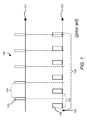
- Figure 1 shows a schematic illustration 100 of the method in the prior art with two time diagrams 101 and 102.
- a base station sends beacons 103 using a beacon period 104, with a typical value range between 10 ms and 100 ms for the beacon period.
- a mobile station starts a measurement procedure initiated by a measurement trigger 105.
- the mobile station performs measurements at time slots 106 to receive either of the beacons 103.
- the time slots 106 are arranged with a slightly different period 107 to have a sliding window in relation to the beacons 103.
- the measurement procedure by the mobile station has to be executed until at least one beacon 103 and one time slot 106 coincide.
- the transmission time of the beacons from the base station to the mobile station for a typical line of sight distance of 1.5 km is around 5 microseconds.
- the time shift, when the beacons are received at the mobile station can be neglected.
- the whole measurement procedure 108 is not finished with the first beacon sent after the measurement trigger. Normally, several beacon periods will elapse until the mobile station can receive and measure one beacon.
- the basic idea of the invention is, that a mobile station can shorten the whole measurement procedure if the mobile station has knowledge about the airtime of the beacons broadcasted by the base station by receiving beacon timing data.
- the beacon timing data consist of time information of the next beacons and this time information is correlated with the system time of the base station. A more detailed description of the beacon timing data is given in the following description according to Figure 2 .
- CPU central processing unit
- a system time clock which provides a system time.
- the system times of a first base station, a second base station and a mobile station are not synchronized in general. Therefore, in addition to transmitting the beacon timing data from the second base station to the mobile station via the first base station an adaptation mechanism is required, which ensures that the time information of the beacon timing data used by the mobile station is adapted to the system time of the mobile station prior to perform the measurement procedure.
- system time information is transmitted between the network nodes involved in performing the invention.
- system time information is transmitted at an arbitrary point in time prior to the transmission of the beacon timing data or at the same time as the transmission of beacon timing data happens.
- the system time information is transmitted to the base station or mobile station at the same time as the beacon timing data is transmitted.
- the first base station knows the transmission and processing time delay for sending the system time information from the second base station to the first base station and the mobile station knows the transmission and processing time delay for sending the system time information from the first base station to the mobile station.
- the time information of the beacon timing data is adapted at the first base station to the system time of the first base station and in a second step, the time information of the beacon timing data is adapted at the mobile station to the system time of the mobile station.
- the method according to the first embodiment of the invention allows to use different system times at the first base station, the second base station and the mobile station.
- Figure 2 shows a first block diagram of a radio communication system 200 in accordance with the first preferred embodiment of the invention.
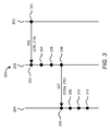
- Figure 3 shows in a sequence of operation diagram 300 a method for preparing and executing measurements at mobile stations to measure the signal quality of received beacons broadcasted from neighbouring base stations performed in the radio communication system 200 shown in Figure 2 .
- Figure 4 shows a schematic illustration 400 to explain the adjustment step of the method of Figure 3 performed at mobile stations.
- the radio communication system 200 of Figure 2 includes a radio access network 201 with a first base station 202, a second base station 203, and a mobile station 204. Further base stations and mobile stations can be included to the radio communication system 200 but are not shown for simplification.
- the first storage medium 206 is foreseen for storing a first executable program 209, which is foreseen for executing steps of a method performed in the first base station 202 according to the first embodiment of the invention.
- the first CPU 205 is foreseen for executing the first executable program 209.
- the first system time clock 207 is foreseen for providing a first system time 210.
- the first register 208 is foreseen for storing a calculated first system time offset 211 between a second system time 218 of the second base station 203 and the first system time 210, a known first transmission and processing time delay 212 between the second base station 203 and the first base station 202 and first recalculated beacon timing data 220a.
- the second base station 203 comprises a second CPU 214, a second storage medium 215, a second system time clock 216 and a second register 217.
- the second storage medium 215 is foreseen for storing a second executable program 218, which is foreseen for executing steps of a method performed in the second base station 203 according to the first embodiment of the invention.
- the second CPU 214 is foreseen for executing the second executable program 218.
- the second system time clock 216 is foreseen for providing a second system time 219.
- the second register 217 is foreseen for storing beacon timing data 220.
- the beacon timing data 220 consist of time information of next beacons to be sent by the second base station 203.
- This time information can consist of time stamps t_b for specific beacons to be sent in the future or it can consist of one time stamp t_b and a beacon period b_p or another combination of time parameters.
- the time information is based on the second system time 219 of the second base station 203.
- the mobile station 204 comprises a third CPU 221, a third storage medium 222, a third system time clock 223, and a third register 224.
- the third storage medium 222 is foreseen for storing a third executable program 225, which is foreseen for executing steps of a method performed in the mobile station 204 according to the first embodiment of the invention.
- the third CPU 221 is foreseen for executing the third executable program 225.
- the third system time clock 223 is foreseen for providing a third system time 226.
- the third register 224 is foreseen for storing a calculated second system time offset 227 between the first system time 210 and the third system time 226, a known second transmission and processing time delay 228 between the first base station 202 and the mobile station 204 and second recalculated beacon timing data 220b.
- the mobile station 204 is connected to the first base station 202 via a radio link 230.
- the first base station and the second base station are connected via a direct communication link 231.
- the second base station 203 is foreseen for broadcasting beacons 232, which can be received and measured by the mobile station 204.
- the sequence of operation diagram 300 depicts steps 301, 303, 304, 305, 306, 308, 309, 310, 311 performed and messages 302, 307 exchanged between the first base station 202, the second base station 203 and the mobile station 204.
- the second base station 203 transmits the beacon timing data 220 stored in the second register 217 and the current second system time 219 in a message 302 to the first base station 202 via the direct communication link 231.
- the first base station 202 receives the message 302.
- the first base station 202 transmits the first recalculated beacon timing data 220a stored in the first register 208 and the current first system time 210 in a message 307 to the mobile station 204.
- the mobile station 204 receives the message 307 in a next step 308.
- the mobile station 204 adjusts at least one time slot to be able to measure at least one of the next beacons 232 broadcasted by the second base station 203 using the second recalculated beacon timing data 220b. This adjustment is clarified in the next paragraph with the description according to figure 4 .
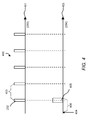
- Figure 4 shows a schematic illustration 400 of two time diagrams 401 and 402 according to the method of figure 3 for preparing and executing measurements at mobile stations to measure the signal quality of received beacons transmitted from neighbouring base stations in the radio communication system of figure 2 in accordance with the first preferred embodiment of the invention.
- the elements in the embodiment shown in figure 4 that correspond to elements of the embodiment of figure 2 have been designated by the same reference numerals.
- the second base station 203 sends beacons 232 using a beacon period 403.
- the beacon period 403 can have the same value at all base stations or the base stations can use different values for the beacon period 403 according to the specification of the radio access technology in use.
- time diagram 402 an adjusted measurement period of the mobile station 204 is shown.
- the mobile station 204 receives the first recalculated beacon timing data 220a and the first system time 210 and recalculates the time information respectively the time stamps of the received first recalculated beacon timing data 220a prior to the measurement and stores the result as beacon timing data 220b as explained in the description of Figure 3 .
- the second recalculated beacon timing data 220b contain time shifted airtime information about the beacons 232.
- the mobile station 204 adjusts at least one measurement time slot 405 to coincide with the airtime of one of the next beacons 232 to be broadcasted by the second base station 203 according to the second recalculated beacon timing data 220b.
- the measurement time slot 405 of figure 4 has been time shifted to the airtime of the next beacon 232 sent by the second base station 203. Therefore, the duration of a measurement procedure 406 according to the first embodiment of the invention is much shorter than the duration of the measurement procedure 108 shown in figure 1 describing the measurement procedure in the prior art.
- the method is initiated by a request for said beacon timing data originated on said one of said mobile stations.
- the mobile station originated beacon timing data request presumes that the mobile station already has information about the existence of the second base station. Such information can be received in advance of any measurement execution e.g. via broadcasted or dedicated neighbourhood information.
- Such mobile station originated beacon timing data request will be preferably used if said one of said mobile stations has a second completely independent receiver chain or even a second completely independent transceiver chain.
- the second completely independent receiver chain is usually of the same radio access technology as the first transceiver chain
- a second completely independent transceiver chain can be of the same but also of another radio access technology as being used by multi-radio capable mobile stations for heterogeneous mobile networks.
- Such mobile stations with a second completely independent receiver chain or a second completely independent transceiver chain are able to perform measurements on beacons of the second base station without interruptions of the data transmission between the mobile station and the first base station but a long measurement procedure with the second completely independent receiver or transceiver chain unnecessary consumes too much electrical resources. Therefore, it is advantageous if the duration of the measurement procedure can be shortened.
- Figure 5 shows in a sequence of operation diagram 500 a method for preparing and executing measurements at mobile stations to measure the signal quality of received beacons transmitted from neighbouring base stations in the radio communication system of figure 2 in accordance with the second preferred embodiment of the invention.
- the elements in the embodiment shown in figure 5 that correspond to elements of the embodiment of figure 2 have been designated by the same reference numerals.
- the sequence of operation diagram 500 depicts steps 501, 503, 504, 506, 507, 509, 510, 511, 512, 514, 515, 516, 517 performed and messages 502, 505, 508, 513 exchanged between the first base station 202, the second base station 203 and the mobile station 204.
- the mobile station 204 transmits a beacon timing data request 502 to the first base station 202.
- the first base station 202 receives the beacon timing data request 502.
- the first base station 202 forwards the beacon timing data request 502 in a message 505 to the second base station 203.
- the second base station 203 receives the message 505.
- the second base station 203 transmits a beacon timing data answer 508 with the beacon timing data 220 and the current second system time 219 to the first base station 202.
- the first base station 202 receives the beacon timing data answer 508.
- the first base station 202 forwards the first recalculated beacon timing data 220a and the current first system time 210 in a beacon timing data answer 513 to the mobile station 204.
- the mobile station 204 receives the beacon timing data answer 513.
- the mobile station 204 adjusts at least one time slot to be able to measure at least one of the next beacons 232 broadcasted by the second base station 203 using the second recalculated beacon timing data 220b. This adjustment is clarified in the previous paragraphs with the description according to figure 4 .
- a method further comprising the step of scheduling at said first base station at least one transmission break for data of said one of said mobile stations taking into account said beacon timing data, wherein said method further comprises the step of deleting information of said beacon timing data at said first base station in such a way that said scheduled transmission breaks are the only components of said beacon timing data.
- Such method in accordance with the third preferred embodiment of the invention is preferably used for measurements within a radio access technology, if a mobile station has only one receiver chain and the serving base station should avoid retransmission of downlink user data.
- Such retransmission is required if the user data have been transmitted during the measurement procedure for the neighbouring base station at the mobile station, in which case the mobile station cannot receive any downlink user data at the same time. Therefore it is favourable, if the base station coordinates data transmission in downlink to the mobile station together with measurements performed by the mobile station.
- a further advantage of the deleting step is that no resources on the radio link are consumed for the redundant information of the beacon timing data.
- Figure 6 shows in a sequence of operation diagram 600 a method for preparing and executing measurements at mobile stations to measure the signal quality of received beacons transmitted from neighbouring base stations in the radio communication system of Figure 2 in accordance the third preferred embodiment of the invention.
- the elements in the embodiment shown in figure 6 that correspond to elements of the embodiment of figure 2 have been designated by the same reference numerals.
- the sequence of operation diagram 600 depicts steps 601, 603, 604, 605, 606, 607, 608, 610, 611, 612, 613 performed and messages 602, 609 exchanged between the first base station 202, the second base station 203 and the mobile station 204.
- the second base station 203 transmits the stored beacon timing data 220 and the current system time 219 in a message 602 to the first base station 202.
- the first base station 202 receives the message 602.
- the first base station 202 schedules at least one transmission break taking into account the first recalculated beacon timing data 220a. This means, that the serving base station schedules no transmission break for downlink data sent to the mobile station 204 for every beacon 232 of the first recalculated beacon timing data 220a but schedules one or more transmission breaks for selected beacons 232.
- the first base station 202 deletes information of the first recalculated beacon timing data 220a by erasing not needed time stamps so that the scheduled transmission breaks are the only components of the first recalculated beacon timing data 220a.
- the origin beacon timing data 220 which comprise the airtime information for several or continuous beacons in the future is reduced, so that only the airtime information for those beacons 232 remain in the first recalculated beacon timing data 220a, which beacons 232 are to be used for the scheduled transmission breaks.
- the scheduling of transmission breaks is for example a procedure similar to UMTS compressed mode (3GPP TS 25.215 V7.4.0 (2007-11).
- the first base station 202 transmits the first recalculated beacon timing data 220a and the current first system time 210 in a message 609 to the mobile station 204.
- the mobile station 204 receives the message 609 in step 610.
- the mobile station 204 adjusts at least one time slot to be able to measure at least one of the next beacons 232 broadcasted by the second base station 203 using the second recalculated beacon timing data 220b. This adjustment is clarified in the previous paragraphs with the description according to figure 4 .
- the airtime of the beacons broadcasted by the second base station and the system times used at the first base station, the second base station and the mobile station are synchronized using satellite or ground based timing modules at the first base station, the second base station and the mobile station.
- Such time synchronization method provides the highest accuracy.
- the timing modules provide a time reference in the first base station, the second base station and the mobile station.
- the time reference can be used to adapt the system times of the first base station, the second base station and the mobile station to said time reference.
- the system time of the mobile station is automatically synchronized to the airtime of the beacons broadcasted by the second base station.
- Figure 7 shows a third block diagram of a radio communication system 700 for preparing and executing measurements at mobile stations to measure the signal quality of received beacons transmitted from neighbouring base stations in accordance with the fourth preferred embodiment of the invention.
- Figure 8 shows in a sequence of operation diagram 800 a method for preparing and executing measurements at mobile stations to measure the signal quality of received beacons broadcasted from neighbouring base stations performed in the radio communication system 700 shown in figure 7 .
- the radio communication network 700 includes a radio access network 701, a first base station 702, a second base station 703, and a mobile station 704. Further base stations and mobile stations can be included to the radio communication system 700 but are not shown for simplification.
- the first storage medium 206 is foreseen for storing a first executable program 209, which is foreseen for executing steps of a method performed in the first base station 702 according to the fourth embodiment of the invention.
- the first CPU 205 is foreseen for executing the first executable program 209.
- the first system time clock 207 is foreseen for providing a first system time 210.
- the first satellite/ground based timing module 705 is foreseen for generating a time reference 706.
- the first system time 210 is adapted to the time reference 706.
- the second base station 703 comprises a second CPU 214, a second storage medium 215, a second system time clock 216, a second register 217 and a second satellite/ground based timing module 707.
- the second storage medium 215 is foreseen for storing a second executable program 218, which is foreseen for executing steps of a method performed in the second base station 703 according to the fourth embodiment of the invention.
- the second CPU 214 is foreseen for executing the second executable program 218.
- the second system time clock 216 is foreseen for providing a second system time 219.
- the second register 217 is foreseen for storing beacon timing data 220.
- the beacon timing data 220 consist of time information of next beacons sent by the second base station 703.
- This time information can consist of time stamps with time t_b for specific beacons to be sent in the future or it can consist of one time stamp with time t_b and a beacon period b_p or another combination of time parameters.
- the time information is based on the second system time 219 of the second base station 703.
- the second satellite/ground based timing module 707 generates the time reference 706.
- the second system time 219 is adapted to the time reference 706.
- the mobile station 704 comprises a third CPU 221, a third storage medium 222, a third system time clock 223, and a third satellite/ground based timing module 708.
- the third storage medium 222 is foreseen for storing a third executable program 225, which is foreseen for executing steps of a method performed in the mobile station 704 according to the fourth embodiment of the invention.
- the third CPU 221 is foreseen for executing the third executable program 225.
- the third system time clock 223 is foreseen for providing a third system time 226.
- the third satellite/ground based timing module 708 if foreseen for generating the time reference 706.
- the third system time 226 is adapted to the time reference 706.
- the mobile station 704 is connected to the first base station 702 via a radio link 230.
- the first base station 702 and the second base station 703 are connected via a direct communication link 231.
- the second base station 703 is foreseen for broadcasting beacons 232, which can be received and measured by the mobile station 704.
- the sequence of operation diagram 800 depicts steps 801, 803, 804, 805, 807, 808, 809 performed and messages 802, 806 exchanged between the first base station 702, the second base station 703 and the mobile station 704.
- the second base station 703 transmits stored beacon timing data 220 and an indication for using the time reference 706 at the second base station 703 in a message 802 to the first base station 702 via the direct communication link 231.
- the indication can be a single flag or single bit added to the beacon timing data 220.
- the first base station 702 receives the message 802.
- the first base station 702 detects that the system times of the second base station 703 and the first base station 702 are adapted to the same time reference 706.
- the first base station 702 transmits the beacon timing data 220 and an indication for using the time reference 706 at the first base station 702 in a message 806 to the mobile station 704.
- the indication can be a single flag or single bit added to the beacon timing data 220.
- the mobile station 704 receives the message 806.
- the mobile station 704 detects that the system times of the mobile station 704 and the first base station 702 are adapted to the same time reference 706.
- the mobile station 704 adjusts at least one time slot to be able to measure at least one of the next beacons 232 broadcasted by the second base station 703 using the beacon timing data 220. This adjustment is clarified in the previous paragraphs with the description according to figure 4 .
- the first base station, the second base station, and the mobile station use a system time adapted to a time reference being generated by a satellite or ground based timing module, because in such a case the transmission of system time information from the second base station to the first base station and from the first base station to the mobile station can be reduced to the transmission of an indication for using a time reference at the sending base station. Furthermore system time offset calculations and beacon timing data recalculations are not required at the first base station and at the mobile station.
- the two time adaptation methods, described by the description and the Figure 3 for the first embodiment of the invention and by the description and Figure 7 for the fourth embodiment of the invention can be mixed up.
- the steps 801, 803, 804 and message 802 of the method according to the fourth embodiment of the invention can be performed in the first part and the steps 306, 308, 309, 310, 311 and message 307 of the method according to the first embodiment of the invention can be performed in the second part of a method according to a fifth embodiment of the invention.
- the mobile station has to measure the beacons of the second base station several times over a longer time period, e.g. the mobile station has interrupted its movement between two cells and is staying at the border of these two cells one belonging the first base station and the other belonging the second base station.
- a second mobile station has to measure the beacons of the same second base station as being done by the first mobile station.
- the first base station can verify, whether temporarily stored beacon timing data can be used for further measurements and it can verify, whether the time information of the beacon timing data is still precisely enough for an additional measurement procedure on a mobile station. If both requirements are fulfilled, the first base station doesn't need to receive or request any new beacon timing data or any new system time information from the second base station.
- the first base station or the mobile station needs to receive or request new system time information from the second base station. If the information of the beacon timing data of the second base station stored at the first base station is outdated, the first base station needs to receive or request new system time information from the second base station.
Abstract
Description
- The invention relates to a method for preparing and executing measurements at mobile stations to measure the signal quality of received beacons transmitted from neighbouring base stations in a radio communication system according to the preamble of claim 1, to such radio communication system according to the preamble of claim 9, to a first base station for use in such radio communication system according to the preamble of claim 10, to a second base station for use in such radio communication system according to the preamble of claim 11, and to a mobile station for use in such radio communication system according to the preamble of claim 12.
- In a radio communication system such as a GSM/GPRS or UMTS/HSPA mobile radio network, a mobile station performs measurements regarding the radio link quality of neighbouring base stations if the radio link to its serving base station is getting worse or fallen below a specific threshold. Such measurements are performed to find an adequate target base station which can take on the active services of the mobile station using a handover procedure.
- The available time to perform such measurements is limited for the following circumstances:
- 1. In a case of abrupt signal degradation of the active radio link between the mobile station and serving base station a neighbouring base station must be found very quickly to achieve a seamless or lossless handover procedure to this base station.
- 2. In heterogeneous mobile radio networks, in which radio access networks with different radio access technologies are overlayed or in homogeneous mobile radio networks with hierarchical cell structures, the number of suitable neighbouring base stations for taking over the services increases. To find the most suited neighbouring radio cell in terms of quality of service (quality of service = QoS), measurement procedures for several candidate radio cells should be carried out.
- To enable these measurements and to enable a synchronization at the mobile station in relation to a base station each base station broadcasts periodically beacons or pilots. The notion beacon will be used in the following for both, beacon and pilot.
- Normally, the base stations are not synchronized to each other. Hence, the mobile station with a single receiver chain cannot receive beacons of a neighbouring base station in parallel to the reception of data from a serving base station even if the serving base station and the neighbouring base station use the same frequency or the same frequency band. Thus, the mobile station must synchronize to the neighbouring base station loosing synchronization to the serving base station. Therefore, the data transmission between the mobile station and the serving base station must be interrupted shortly for the duration of the measurement procedure. An interruption induced by such a measurement should fulfil the QoS requirements of the active services of the mobile station. Especially for a real-time service such as voice over IP a one-way latency (mouth to ear) of more than 150 ms and packet loss of two or more packets in a 20 ms (default) packetization interval results in a noticeable degradation of voice quality. Therefore, the transmission interruption for a single measurement time slot has to be limited to definitely less than 40 ms. A typical beacon period in for example a wireless local area network is 100 ms.
- The duration of the measurement procedure at the mobile station depends on the time needed to synchronize the measurement time slots at the mobile station with the beacons sent by the neighbouring base station. Dependent on the maximum measurement time slot (e.g. 40 ms as mentioned above) and the time gap between the beacons (e.g. 100 ms as mentioned above), it is possible that there is no time overlap between the measurement time and the next beacon airtime by using only one measurement time slot. In this case several measurement time slots with relevant data transmission interruptions have to be used and therefore, the complete measurement procedure can take up to a second or more.
- A long measurement procedure for only one neighbouring base station results in a very limited number of neighbouring base stations which can be evaluated in a reasonable time and can result in a loss or delay of data, if the radio link to the serving base station degrades in a too fast way.
- Furthermore, measurement time is wasted on the one hand between the starting time of the measurement time slot and the reception time of the beacon and on the other hand between the reception time of the beacon and the ending time of the measurement time slot.
- It is favourable if the mobile station has knowledge about the airtime of the beacons broadcasted by neighbouring base stations. In such a case adverse effects on the running services can be minimised and the power consumption related to measurements of neighbouring base station can be reduced.
- We have in-house knowledge about a method of optimizing measurement duration in a telecommunications network. Such telecommunications network comprises a first base station connected to a first radio network, at least a second base station connected to a second radio network, a core network connected to the first and second radio network and a database coupled to the core network. The relevant steps according to this method are: sending at least a second beacon period information belonging to the second base station from the second base station to the database, storing the second beacon period information on the database, sending a request of the second beacon period information from the first base station to the database, generating a response of the second beacon period information belonging to the second base station from the database to the first base station, forwarding the response received at the first base station to the mobile station and adjusting measurements periods on the mobile station based on the response of the beacon period information. This method works especially for heterogeneous mobile networks like 3GPP SAE with base stations located in different radio access networks.
- This optimization method shortens the measurement duration but requires a database as an additional network element. Such database induces additional asset costs and requires signalling effort from the base stations to the database and from the database to the base stations.
- For optimizing the preparation and execution of measurements especially in homogeneous radio communication systems with base stations using the same radio access technology, a method and a radio communication system, base stations and a mobile terminal performing said method are described in this invention.
- The present invention provides a method for preparing and executing of measurements at mobile stations to measure the signal quality of received beacons transmitted from neighbouring base stations in a radio communication system, said radio communication system comprising a radio access network with a first base station, at least one second base station, and at least one mobile station, said first base station being a serving base station of said one of said mobile stations, said one of said second base stations broadcasting beacons repeatedly, the method comprising the steps of: transmitting beacon timing data from said one of said second base stations to said first base station, transmitting said beacon timing data or recalculated beacon timing data from said first base station to said one of said mobile stations, and adjusting at least one time slot for performing a measurement on said beacons at said one of said mobile stations using said beacon timing data or recalculated beacon timing data, wherein when said first base station is connected to said one of said second base stations via a direct communication link transmitting said beacon timing data via said direct communication link from said one of said second base stations to said first base station.
- It is to be noted, that such direct communication links are known, e.g. from the overall architecture of E-UTRAN described in 3GPP TS 36.300 V8.2.0 (2007-09) with X2 interfaces between base stations (eNBs).
- By using such a method the beacon timing data are sent directly from the second base station to the first base station avoiding the detour via a database and avoiding the need of the database as an additional network element. This property accelerates the preparation and execution process of the measurement. The beacon timing data can be requested by the first base station, it can be requested by the mobile station via the first base station, it can be sent periodically by the second base station to the first base station, it can be stored temporarily at the first base station or any other method can be used in accordance with the invention.
- Time adaptation (or time synchronization) is required at the first base station and at the mobile station between the beacon timing data and the system time used at the first base station and the mobile station, because the beacon timing data are based on the system time of the second base station and the system times of the second base station, the first base station and the mobile station differ in general. If the mobile station receives beacon timing data and the system time of the mobile station is different to the system time of the second base station, the mobile station is not able to adjust in an accurate way a single measurement time slot to the airtime of one of the next beacons broadcasted by the second base station. Furthermore, if the first base station receives beacon timing data and the system time of the first base station is different to the system time of the second base station, the first base station is not able to schedule at said first base station at least one transmission break for data of said one of said mobile stations in an accurate way.
- Time adaptation at the mobile station and the first base station can be based on a comparison of system times taking into account the transmission and processing time delay for the transmission of the beacon timing data between the transmitting nodes and the receiving nodes if necessary, it can be based on system times adapted to a time reference, which is generated by satellite or ground based timing modules or it can be based on any other method not explicitly mentioned in this invention.
- Other characteristics and advantages of the invention will become apparent in the following detailed description of preferred embodiments of the invention. The preferred embodiments of the invention will be illustrated by the accompanying drawings given by way of non-limiting illustrations.
-
Figure 1 is a schematic illustration in the prior art of a method for executing measurements at mobile stations to measure the signal quality of beacons periodically broadcasted from neighbouring base stations. -
Figure 2 shows a first block diagram of a radio communication system to measure the signal quality of received beacons transmitted from neighbouring base stations in accordance with a first preferred embodiment of the invention. -
Figure 3 shows a method for preparing and executing measurements at mobile stations to measure the signal quality of received beacons transmitted from neighbouring base stations in the radio communication system ofFigure 2 in accordance with the first preferred embodiment of the invention. -
Figure 4 is a schematic illustration of two time diagrams according to the method ofFigure 3 for preparing and executing measurements at mobile stations to measure the signal quality of received beacons transmitted from neighbouring base stations in the radio communication system ofFigure 2 in accordance with the first preferred embodiment of the invention. -
Figure 5 shows a method for preparing and executing measurements at mobile stations to measure the signal quality of received beacons transmitted from neighbouring base stations in the radio communication system ofFigure 2 in accordance with a second preferred embodiment of the invention. -
Figure 6 shows a method for preparing and executing measurements at mobile stations to measure the signal quality of received beacons transmitted from neighbouring base stations in the radio communication system ofFigure 2 in accordance with a third preferred embodiment of the invention. -
Figure 7 shows a second block diagram of a radio communication system for preparing and executing measurements at mobile stations to measure the signal quality of received beacons transmitted from neighbouring base stations in accordance with a fourth preferred embodiment of the invention. -
Figure 8 shows a method for preparing and executing measurements at mobile stations to measure the signal quality of received beacons transmitted from neighbouring base stations in the radio communication system ofFigure 7 in accordance with the fourth preferred embodiment of the invention. - In a method according to the prior art, a neighbouring base station broadcasts beacons periodically. A mobile station with a single receiver and an active session can perform measurements on these beacons not in a single step with a long measurement time slot as long as the next beacon is received but with several steps using short measurement time slots, in which the active session is shortly interrupted. These short measurement time slots are used until one of the next beacons is received.
-
Figure 1 shows aschematic illustration 100 of the method in the prior art with two time diagrams 101 and 102. In time diagram 101 a base station sendsbeacons 103 using abeacon period 104, with a typical value range between 10 ms and 100 ms for the beacon period. In the time diagram 102 a mobile station starts a measurement procedure initiated by ameasurement trigger 105. The mobile station performs measurements attime slots 106 to receive either of thebeacons 103. Thetime slots 106 are arranged with a slightlydifferent period 107 to have a sliding window in relation to thebeacons 103. The measurement procedure by the mobile station has to be executed until at least onebeacon 103 and onetime slot 106 coincide. The transmission time of the beacons from the base station to the mobile station for a typical line of sight distance of 1.5 km is around 5 microseconds. In comparison to the value of the beacon period the time shift, when the beacons are received at the mobile station can be neglected. AsFigure 1 shows, thewhole measurement procedure 108 is not finished with the first beacon sent after the measurement trigger. Normally, several beacon periods will elapse until the mobile station can receive and measure one beacon. - The basic idea of the invention is, that a mobile station can shorten the whole measurement procedure if the mobile station has knowledge about the airtime of the beacons broadcasted by the base station by receiving beacon timing data. The beacon timing data consist of time information of the next beacons and this time information is correlated with the system time of the base station. A more detailed description of the beacon timing data is given in the following description according to
Figure 2 . - In general each electronic device with a central processing unit (CPU = central processing unit) is also equipped with a system time clock, which provides a system time. In accordance with a first embodiment of the invention the system times of a first base station, a second base station and a mobile station are not synchronized in general. Therefore, in addition to transmitting the beacon timing data from the second base station to the mobile station via the first base station an adaptation mechanism is required, which ensures that the time information of the beacon timing data used by the mobile station is adapted to the system time of the mobile station prior to perform the measurement procedure.
- One possibility for such an adaptation mechanism, which requires no additional hardware components in the network nodes of a radio communication system is to transmit system time information between the network nodes involved in performing the invention. In this case, it is required that system time information is transmitted at an arbitrary point in time prior to the transmission of the beacon timing data or at the same time as the transmission of beacon timing data happens. In the first preferred embodiment of the invention, the system time information is transmitted to the base station or mobile station at the same time as the beacon timing data is transmitted. The first base station knows the transmission and processing time delay for sending the system time information from the second base station to the first base station and the mobile station knows the transmission and processing time delay for sending the system time information from the first base station to the mobile station. In a first step, the time information of the beacon timing data is adapted at the first base station to the system time of the first base station and in a second step, the time information of the beacon timing data is adapted at the mobile station to the system time of the mobile station. The method according to the first embodiment of the invention allows to use different system times at the first base station, the second base station and the mobile station.
-
Figure 2 shows a first block diagram of aradio communication system 200 in accordance with the first preferred embodiment of the invention.Figure 3 shows in a sequence of operation diagram 300 a method for preparing and executing measurements at mobile stations to measure the signal quality of received beacons broadcasted from neighbouring base stations performed in theradio communication system 200 shown inFigure 2 .Figure 4 shows aschematic illustration 400 to explain the adjustment step of the method ofFigure 3 performed at mobile stations. - The
radio communication system 200 ofFigure 2 includes aradio access network 201 with afirst base station 202, asecond base station 203, and amobile station 204. Further base stations and mobile stations can be included to theradio communication system 200 but are not shown for simplification. - The
first base station 202 comprises a first central processing unit (central processing unit = CPU) 205, afirst storage medium 206, a firstsystem time clock 207, and afirst register 208. Thefirst storage medium 206 is foreseen for storing a firstexecutable program 209, which is foreseen for executing steps of a method performed in thefirst base station 202 according to the first embodiment of the invention. Thefirst CPU 205 is foreseen for executing the firstexecutable program 209. The firstsystem time clock 207 is foreseen for providing afirst system time 210. Thefirst register 208 is foreseen for storing a calculated first system time offset 211 between asecond system time 218 of thesecond base station 203 and thefirst system time 210, a known first transmission andprocessing time delay 212 between thesecond base station 203 and thefirst base station 202 and first recalculatedbeacon timing data 220a. - The
second base station 203 comprises asecond CPU 214, asecond storage medium 215, a secondsystem time clock 216 and asecond register 217. Thesecond storage medium 215 is foreseen for storing a secondexecutable program 218, which is foreseen for executing steps of a method performed in thesecond base station 203 according to the first embodiment of the invention. Thesecond CPU 214 is foreseen for executing the secondexecutable program 218. The secondsystem time clock 216 is foreseen for providing asecond system time 219. Thesecond register 217 is foreseen for storingbeacon timing data 220. Thebeacon timing data 220 consist of time information of next beacons to be sent by thesecond base station 203. This time information can consist of time stamps t_b for specific beacons to be sent in the future or it can consist of one time stamp t_b and a beacon period b_p or another combination of time parameters. The time information is based on thesecond system time 219 of thesecond base station 203. - The
mobile station 204 comprises athird CPU 221, athird storage medium 222, a thirdsystem time clock 223, and a third register 224. Thethird storage medium 222 is foreseen for storing a thirdexecutable program 225, which is foreseen for executing steps of a method performed in themobile station 204 according to the first embodiment of the invention. Thethird CPU 221 is foreseen for executing the thirdexecutable program 225. The thirdsystem time clock 223 is foreseen for providing athird system time 226. The third register 224 is foreseen for storing a calculated second system time offset 227 between thefirst system time 210 and thethird system time 226, a known second transmission andprocessing time delay 228 between thefirst base station 202 and themobile station 204 and second recalculatedbeacon timing data 220b. - The
mobile station 204 is connected to thefirst base station 202 via aradio link 230. The first base station and the second base station are connected via adirect communication link 231. Thesecond base station 203 is foreseen for broadcastingbeacons 232, which can be received and measured by themobile station 204. - The elements in the embodiment shown in
figure 3 that correspond to elements of the embodiment offigure 2 have been designated by the same reference numerals. - The sequence of operation diagram 300 depicts
steps messages first base station 202, thesecond base station 203 and themobile station 204. - In a
first step 301, thesecond base station 203 transmits thebeacon timing data 220 stored in thesecond register 217 and the currentsecond system time 219 in amessage 302 to thefirst base station 202 via thedirect communication link 231. In anext step 303, thefirst base station 202 receives themessage 302. In afurther step 304, thefirst base station 202 calculates the first system time offset 211 in consideration of its ownfirst system time 210, the receivedsecond system time 219 and the stored first transmission andprocessing time delay 212 using the following equation:
- In a
next step 305, thefirst base station 202 recalculates the time information respectively the time stamps t_b of thebeacon timing data 220 in consideration of the calculated first system time offset 211 and calculates time stamps t_b_a using the following equation and stores the result as first recalculatedbeacon timing data 220a in the first register 208:
- In a
further step 306 thefirst base station 202 transmits the first recalculatedbeacon timing data 220a stored in thefirst register 208 and the currentfirst system time 210 in amessage 307 to themobile station 204. Themobile station 204 receives themessage 307 in anext step 308. In afurther step 309, themobile station 204 calculates the second system time offset 227 in consideration of its ownthird system time 226, the receivedfirst system time 210 and the known second transmission andprocessing time delay 228 using the following equation:
- In a
next step 310, themobile station 204 recalculates the time information respectively the time stamps t_b_a of thebeacon timing data 220 in consideration of the calculated second system time offset 227 and calculates time stamps t_b_b using the following equation and stores the result as second recalculatedbeacon timing data 220b in the third register 224:
- In a
final step 311, themobile station 204 adjusts at least one time slot to be able to measure at least one of thenext beacons 232 broadcasted by thesecond base station 203 using the second recalculatedbeacon timing data 220b. This adjustment is clarified in the next paragraph with the description according tofigure 4 . -
Figure 4 shows aschematic illustration 400 of two time diagrams 401 and 402 according to the method offigure 3 for preparing and executing measurements at mobile stations to measure the signal quality of received beacons transmitted from neighbouring base stations in the radio communication system offigure 2 in accordance with the first preferred embodiment of the invention. The elements in the embodiment shown infigure 4 that correspond to elements of the embodiment offigure 2 have been designated by the same reference numerals. - In time diagram 401 the
second base station 203 sendsbeacons 232 using abeacon period 403. Thebeacon period 403 can have the same value at all base stations or the base stations can use different values for thebeacon period 403 according to the specification of the radio access technology in use. - In time diagram 402 an adjusted measurement period of the
mobile station 204 is shown. When themobile station 204 is required to measure thebeacons 232 of thesecond base station 203, themobile station 204 receives the first recalculatedbeacon timing data 220a and thefirst system time 210 and recalculates the time information respectively the time stamps of the received first recalculatedbeacon timing data 220a prior to the measurement and stores the result asbeacon timing data 220b as explained in the description ofFigure 3 . The second recalculatedbeacon timing data 220b contain time shifted airtime information about thebeacons 232. Once the second recalculatedbeacon timing data 220b are available at themobile station 204 at a point intime 404, which can be a measurement trigger, themobile station 204 adjusts at least onemeasurement time slot 405 to coincide with the airtime of one of thenext beacons 232 to be broadcasted by thesecond base station 203 according to the second recalculatedbeacon timing data 220b. In comparison to the firstmeasurement time slot 106 offigure 1 , themeasurement time slot 405 offigure 4 has been time shifted to the airtime of thenext beacon 232 sent by thesecond base station 203. Therefore, the duration of ameasurement procedure 406 according to the first embodiment of the invention is much shorter than the duration of themeasurement procedure 108 shown infigure 1 describing the measurement procedure in the prior art. - In a second preferred embodiment of the invention the method is initiated by a request for said beacon timing data originated on said one of said mobile stations. The mobile station originated beacon timing data request presumes that the mobile station already has information about the existence of the second base station. Such information can be received in advance of any measurement execution e.g. via broadcasted or dedicated neighbourhood information.
- Such mobile station originated beacon timing data request will be preferably used if said one of said mobile stations has a second completely independent receiver chain or even a second completely independent transceiver chain. Whereas the second completely independent receiver chain is usually of the same radio access technology as the first transceiver chain, a second completely independent transceiver chain can be of the same but also of another radio access technology as being used by multi-radio capable mobile stations for heterogeneous mobile networks. Such mobile stations with a second completely independent receiver chain or a second completely independent transceiver chain are able to perform measurements on beacons of the second base station without interruptions of the data transmission between the mobile station and the first base station but a long measurement procedure with the second completely independent receiver or transceiver chain unnecessary consumes too much electrical resources. Therefore, it is advantageous if the duration of the measurement procedure can be shortened.
-
Figure 5 shows in a sequence of operation diagram 500 a method for preparing and executing measurements at mobile stations to measure the signal quality of received beacons transmitted from neighbouring base stations in the radio communication system offigure 2 in accordance with the second preferred embodiment of the invention. The elements in the embodiment shown infigure 5 that correspond to elements of the embodiment offigure 2 have been designated by the same reference numerals. - The sequence of operation diagram 500 depicts
steps messages first base station 202, thesecond base station 203 and themobile station 204. - In a
first step 501, themobile station 204 transmits a beacon timing data request 502 to thefirst base station 202. In anext step 503, thefirst base station 202 receives the beacon timingdata request 502. In afurther step 504, thefirst base station 202 forwards the beacon timing data request 502 in amessage 505 to thesecond base station 203. In anext step 506, thesecond base station 203 receives themessage 505. In afurther step 507, thesecond base station 203 transmits a beacon timing data answer 508 with thebeacon timing data 220 and the currentsecond system time 219 to thefirst base station 202. In anext step 509, thefirst base station 202 receives the beacon timing data answer 508. In afurther step 510, thefirst base station 202 calculates the first system time offset 211 in consideration of its ownfirst system time 210, the receivedsecond system time 219 and the known first transmission andprocessing time delay 212 using the following equation:
- In a
next step 511, thefirst base station 202 recalculates the time information respectively the time stamps t_b of thebeacon timing data 220 in consideration of the calculated first system time offset 211 and calculates time stamps t_b_a using the following equation and stores the result as first recalculatedbeacon timing data 220a in the first register 208:
- In a
next step 512, thefirst base station 202 forwards the first recalculatedbeacon timing data 220a and the currentfirst system time 210 in a beacon timing data answer 513 to themobile station 204. In afurther step 514, themobile station 204 receives the beacon timing data answer 513. In anext step 515, themobile station 204 calculates the second system time offset 227 in consideration of its ownthird system time 226, the receivedfirst system time 210 and the known second transmission andprocessing time delay 228 using the following equation:
- In a
further step 516, themobile station 204 recalculates the time information respectively the time stamps t_b_a of the first recalculatedbeacon timing data 220a in consideration of the calculated second system time offset 227 and calculates time stamps t_b_b using the following equation and stores the result as second recalculatedbeacon timing data 220b in the third register 224:
- In a
final step 517, themobile station 204 adjusts at least one time slot to be able to measure at least one of thenext beacons 232 broadcasted by thesecond base station 203 using the second recalculatedbeacon timing data 220b. This adjustment is clarified in the previous paragraphs with the description according tofigure 4 . - In a third preferred embodiment of the invention it is a method further comprising the step of scheduling at said first base station at least one transmission break for data of said one of said mobile stations taking into account said beacon timing data, wherein said method further comprises the step of deleting information of said beacon timing data at said first base station in such a way that said scheduled transmission breaks are the only components of said beacon timing data.
- Such method in accordance with the third preferred embodiment of the invention is preferably used for measurements within a radio access technology, if a mobile station has only one receiver chain and the serving base station should avoid retransmission of downlink user data. Such retransmission is required if the user data have been transmitted during the measurement procedure for the neighbouring base station at the mobile station, in which case the mobile station cannot receive any downlink user data at the same time. Therefore it is favourable, if the base station coordinates data transmission in downlink to the mobile station together with measurements performed by the mobile station. A further advantage of the deleting step is that no resources on the radio link are consumed for the redundant information of the beacon timing data.
-
Figure 6 shows in a sequence of operation diagram 600 a method for preparing and executing measurements at mobile stations to measure the signal quality of received beacons transmitted from neighbouring base stations in the radio communication system ofFigure 2 in accordance the third preferred embodiment of the invention. The elements in the embodiment shown infigure 6 that correspond to elements of the embodiment offigure 2 have been designated by the same reference numerals. - The sequence of operation diagram 600 depicts
steps messages first base station 202, thesecond base station 203 and themobile station 204. - In a
first step 601, thesecond base station 203 transmits the storedbeacon timing data 220 and thecurrent system time 219 in amessage 602 to thefirst base station 202. In anext step 603, thefirst base station 202 receives themessage 602. In afurther step 604, thefirst base station 202 calculates the first system time offset 211 in consideration of its ownfirst system time 210, the receivedsecond system time 219 and the known first transmission andprocessing time delay 212 using the following equation:
- In a
next step 605, thefirst base station 202 recalculates the time information respectively the time stamps t_b of thebeacon timing data 220 in consideration of the calculated first system time offset 211 and calculates time stamps t_b_a using the following equation and stores the result as first recalculatedbeacon timing data 220a in the first register 208:
- In a
further step 606, thefirst base station 202 schedules at least one transmission break taking into account the first recalculatedbeacon timing data 220a. This means, that the serving base station schedules no transmission break for downlink data sent to themobile station 204 for everybeacon 232 of the first recalculatedbeacon timing data 220a but schedules one or more transmission breaks for selectedbeacons 232. In anext step 607, thefirst base station 202 deletes information of the first recalculatedbeacon timing data 220a by erasing not needed time stamps so that the scheduled transmission breaks are the only components of the first recalculatedbeacon timing data 220a. In other words, the originbeacon timing data 220, which comprise the airtime information for several or continuous beacons in the future is reduced, so that only the airtime information for thosebeacons 232 remain in the first recalculatedbeacon timing data 220a, whichbeacons 232 are to be used for the scheduled transmission breaks. The scheduling of transmission breaks is for example a procedure similar to UMTS compressed mode (3GPP TS 25.215 V7.4.0 (2007-11). - In a
further step 608 thefirst base station 202 transmits the first recalculatedbeacon timing data 220a and the currentfirst system time 210 in amessage 609 to themobile station 204. Themobile station 204 receives themessage 609 instep 610. In anext step 611, themobile station 204 calculates the second system time offset 227 in consideration of its ownthird system time 226, the receivedfirst system time 210 and the known second transmission andprocessing time delay 228 using the following equation:
- In a
further step 612, themobile station 204 recalculates the time stamps t_b_a of the first recalculatedbeacon timing data 220a in consideration of the calculated second system time offset 227 and calculates time stamps t_b_b using the following equation and stores the result as second recalculatedbeacon timing data 220b in the third register 224:
- In a
final step 613, themobile station 204 adjusts at least one time slot to be able to measure at least one of thenext beacons 232 broadcasted by thesecond base station 203 using the second recalculatedbeacon timing data 220b. This adjustment is clarified in the previous paragraphs with the description according tofigure 4 . - In a fourth preferred embodiment of the invention the airtime of the beacons broadcasted by the second base station and the system times used at the first base station, the second base station and the mobile station are synchronized using satellite or ground based timing modules at the first base station, the second base station and the mobile station. Such time synchronization method provides the highest accuracy. The timing modules provide a time reference in the first base station, the second base station and the mobile station. The time reference can be used to adapt the system times of the first base station, the second base station and the mobile station to said time reference. By using such method the system time of the mobile station is automatically synchronized to the airtime of the beacons broadcasted by the second base station.
-
Figure 7 shows a third block diagram of aradio communication system 700 for preparing and executing measurements at mobile stations to measure the signal quality of received beacons transmitted from neighbouring base stations in accordance with the fourth preferred embodiment of the invention.Figure 8 shows in a sequence of operation diagram 800 a method for preparing and executing measurements at mobile stations to measure the signal quality of received beacons broadcasted from neighbouring base stations performed in theradio communication system 700 shown infigure 7 . - The elements in the embodiment shown in
figure 7 that correspond to elements of the embodiment offigure 2 have been designated by the same reference numerals. - The
radio communication network 700 includes aradio access network 701, afirst base station 702, asecond base station 703, and amobile station 704. Further base stations and mobile stations can be included to theradio communication system 700 but are not shown for simplification. - The
first base station 702 comprises a first central processing unit (central processing unit = CPU) 205, afirst storage medium 206, a firstsystem time clock 207, and a first satellite/ground basedtiming module 705. Thefirst storage medium 206 is foreseen for storing a firstexecutable program 209, which is foreseen for executing steps of a method performed in thefirst base station 702 according to the fourth embodiment of the invention. Thefirst CPU 205 is foreseen for executing the firstexecutable program 209. The firstsystem time clock 207 is foreseen for providing afirst system time 210. The first satellite/ground basedtiming module 705 is foreseen for generating atime reference 706. Thefirst system time 210 is adapted to thetime reference 706. - The
second base station 703 comprises asecond CPU 214, asecond storage medium 215, a secondsystem time clock 216, asecond register 217 and a second satellite/ground basedtiming module 707. Thesecond storage medium 215 is foreseen for storing a secondexecutable program 218, which is foreseen for executing steps of a method performed in thesecond base station 703 according to the fourth embodiment of the invention. Thesecond CPU 214 is foreseen for executing the secondexecutable program 218. The secondsystem time clock 216 is foreseen for providing asecond system time 219. Thesecond register 217 is foreseen for storingbeacon timing data 220. Thebeacon timing data 220 consist of time information of next beacons sent by thesecond base station 703. This time information can consist of time stamps with time t_b for specific beacons to be sent in the future or it can consist of one time stamp with time t_b and a beacon period b_p or another combination of time parameters. The time information is based on thesecond system time 219 of thesecond base station 703. The second satellite/ground basedtiming module 707 generates thetime reference 706. Thesecond system time 219 is adapted to thetime reference 706. - The
mobile station 704 comprises athird CPU 221, athird storage medium 222, a thirdsystem time clock 223, and a third satellite/ground basedtiming module 708. Thethird storage medium 222 is foreseen for storing a thirdexecutable program 225, which is foreseen for executing steps of a method performed in themobile station 704 according to the fourth embodiment of the invention. Thethird CPU 221 is foreseen for executing the thirdexecutable program 225. The thirdsystem time clock 223 is foreseen for providing athird system time 226. The third satellite/ground basedtiming module 708 if foreseen for generating thetime reference 706. Thethird system time 226 is adapted to thetime reference 706. - The
mobile station 704 is connected to thefirst base station 702 via aradio link 230. Thefirst base station 702 and thesecond base station 703 are connected via adirect communication link 231. Thesecond base station 703 is foreseen for broadcastingbeacons 232, which can be received and measured by themobile station 704. - The elements in the embodiment shown in
figure 8 that correspond to elements of the embodiment offigure 2 andfigure 7 have been designated by the same reference numerals. - The sequence of operation diagram 800 depicts
steps messages first base station 702, thesecond base station 703 and themobile station 704. - In a
first step 801, thesecond base station 703 transmits storedbeacon timing data 220 and an indication for using thetime reference 706 at thesecond base station 703 in amessage 802 to thefirst base station 702 via thedirect communication link 231. The indication can be a single flag or single bit added to thebeacon timing data 220. In anext step 803, thefirst base station 702 receives themessage 802. In afurther step 804, thefirst base station 702 detects that the system times of thesecond base station 703 and thefirst base station 702 are adapted to thesame time reference 706. In anext step 805, thefirst base station 702 transmits thebeacon timing data 220 and an indication for using thetime reference 706 at thefirst base station 702 in amessage 806 to themobile station 704. The indication can be a single flag or single bit added to thebeacon timing data 220. In anext step 807, themobile station 704 receives themessage 806. In afurther step 808, themobile station 704 detects that the system times of themobile station 704 and thefirst base station 702 are adapted to thesame time reference 706. In afinal step 809, themobile station 704 adjusts at least one time slot to be able to measure at least one of thenext beacons 232 broadcasted by thesecond base station 703 using thebeacon timing data 220. This adjustment is clarified in the previous paragraphs with the description according tofigure 4 . - It's favourable, that the first base station, the second base station, and the mobile station use a system time adapted to a time reference being generated by a satellite or ground based timing module, because in such a case the transmission of system time information from the second base station to the first base station and from the first base station to the mobile station can be reduced to the transmission of an indication for using a time reference at the sending base station. Furthermore system time offset calculations and beacon timing data recalculations are not required at the first base station and at the mobile station.
- The two time adaptation methods, described by the description and the
Figure 3 for the first embodiment of the invention and by the description andFigure 7 for the fourth embodiment of the invention can be mixed up. For example, if the first base station and the second base station comprise a satellite or ground based timing module each but the mobile station does not comprise a satellite or ground based timing module, thesteps message 802 of the method according to the fourth embodiment of the invention can be performed in the first part and thesteps message 307 of the method according to the first embodiment of the invention can be performed in the second part of a method according to a fifth embodiment of the invention. - Within certain conditions, the mobile station has to measure the beacons of the second base station several times over a longer time period, e.g. the mobile station has interrupted its movement between two cells and is staying at the border of these two cells one belonging the first base station and the other belonging the second base station. In another case it is possible, that a second mobile station has to measure the beacons of the same second base station as being done by the first mobile station. In this cases the first base station can verify, whether temporarily stored beacon timing data can be used for further measurements and it can verify, whether the time information of the beacon timing data is still precisely enough for an additional measurement procedure on a mobile station. If both requirements are fulfilled, the first base station doesn't need to receive or request any new beacon timing data or any new system time information from the second base station. If the time basis of the beacon timing data of the second base station isn't precisely enough any more which is generally the case if no ground or satellite based timing modules are used, the first base station or the mobile station needs to receive or request new system time information from the second base station. If the information of the beacon timing data of the second base station stored at the first base station is outdated, the first base station needs to receive or request new system time information from the second base station.
Claims (12)
- A method for preparing and executing of measurements at mobile stations to measure the signal quality of received beacons broadcasted from neighbouring base stations in a radio communication system (200, 700), said radio communication system (200, 700) comprising a radio access network (201, 701) with a first base station (202, 702), at least one second base station (203, 703), and at least one mobile station (204, 704), said first base station (202, 702) being a serving base station of said one of said mobile stations (204, 704), said one of said second base stations (203, 703) broadcasting beacons (232) repeatedly, the method comprising the steps of:transmitting beacon timing data (220) from said one of said second base stations (203, 703) to said first base station (202, 702), transmitting beacon timing data (220, 220a) from said first base station (202, 702) to said one of said mobile stations (204, 704), and adjusting at least one time slot for performing a measurement on said beacons (232) at said one of said mobile stations (204, 704) using beacon timing data (220, 220a, 220b),characterized in,when said first base station (202, 702) is connected to said one of said second base stations (203, 703) via a direct communication link (231), transmitting said beacon timing data (220) via said direct communication link (231) from said one of said second base stations (203, 703) to said first base station (202, 702).
- The method according to claim 1, characterized in that as a precondition for performing the preparing and executing of measurements the method further comprises the steps of performing time adaptation at said first base station (202, 702) between said beacon timing data (220) and a first system time (210) of said first base station (202, 702) and performing time adaptation at said one of said mobile stations (204, 704) between said beacon timing data (220, 220a) and a third system time (226) of said one of said mobile stations (204, 704).
- The method according to claim 2, characterized in that said time adaptation at said first base station (202) is performed by the steps of transmitting a second system time (219) of said one of said second base stations (203) from said one of said second base stations (203) to said first base station (202) via said direct communication link (231), calculating at said first base station (202) a first system time offset (211) between said second system time (219) and said first system time (210) in consideration of said first system time (210) and said second system time (219),
recalculating at said first base station (202) time stamps of said beacon timing data (220) in consideration of said first system time offset (211) and
using the result as first recalculated beacon timing data (220a). - The method according to claim 2, characterized in that said time adaptation at said one of said mobile stations (203) is performed by the steps of
transmitting said first system time (210) from said first base station (202, 702) to said one of said mobile stations (204),
calculating at said one of said mobile stations (204) a second system time offset (227) between said first system time (210) and said third system time (226) in consideration of said third system time (226) and said first system time (210),
recalculating at said one of said mobile stations (204) time stamps of said beacon timing data (220, 220a) in consideration of said second system time offset (227) and
using the result as second recalculated beacon timing data (220b). - The method according to claim 2, characterized in that,
when said first base station (702) further comprises a first satellite or ground based timing module (705) for generating a time reference (706), said first system time (210) is adapted to said time reference (706) and said one of said second base stations (703) further comprises a second satellite or ground based timing module (707) for generating said time reference (706) and said second system time (219) is adapted to said time reference (706),
said time adaptation at said first base station (702) is performed by the step of
transmitting from said one of said second base stations (703) to said first base station (702) via said direct communication link (231) an indication for using said reference time (706) at said one of said second base stations (703). - The method according to claim 2, characterized in that,
when said first base station (702) further comprises a first satellite or ground based timing module (705) for generating a time reference (706), said first system time (210) is adapted to said time reference (706) and said one of said mobile stations (704) further comprises a third satellite or ground based timing module (708) for generating said time reference (706) and said third system time (226) is adapted to said time reference (706),
said time adaptation at said one of said mobile stations (703) is performed by the step of
transmitting from said first base stations (702) to said one of said mobile stations (704) an indication for using said reference time (706) at said first base stations (702). - The method according to claim 1, characterized in the method further comprising the step of forwarding a beacon timing data request (502) by said first base station (202, 702) from said one of said mobile stations (204, 704) to said one of said second base stations (203, 703) via said direct communication link (231).
- The method according to claim 1, characterized in the method further comprising the steps of
scheduling at said first base station (202, 702) at least one transmission break for data of said one of said mobile stations (204, 704) taking into account said beacon timing data (220, 220a) and deleting information of said beacon timing data (220, 220a) at said first base station (202, 702) in such a way that said scheduled transmission breaks are the only components of said beacon timing data (220, 220a). - A radio communication system (200, 700) for preparing and executing measurements at mobile stations to measure the signal quality of received beacons broadcasted from neighbouring base stations, said radio communication system (200, 700) comprising a radio access network (201, 701) with a first base station (202, 702), at least one second base station (203, 703), and at least one mobile station (204, 704), said first base station (202, 702) being a serving base station of said one of said mobile stations (204, 704), said one of said second base stations (203, 703) broadcasting beacons (232) repeatedly, the radio communication system (200, 700) further comprising:means for transmitting said beacon timing data (220) from said one of said second base stations (203, 703) to said first base station (202, 702),means for performing time adaptation at said first base station (202, 702) between said beacon timing data (220) and a first system time (210) of said first base station (202, 702),means for transmitting beacon timing data (220, 220a) from said first base station (202, 702) to said one of said mobile stations (204, 704), means for performing time adaptation at said one of said mobile stations (204, 704) between said beacon timing data (220, 220a) and said third system time (226), andmeans for adjusting at least one time slot for performing a measurement on said beacons (232) at said one of said mobile stations (204, 704) using said beacon timing data (220) or recalculated beacon timing data (220a, 220b),characterized in that said first base station (202, 702) is connected to said one of said second base stations (203, 703) via a direct communication link (231) and said means for transmitting said beacon timing data (220) from said one of said second base stations (203, 703) to said first base station (202, 702) are interfaced to said direct communication link (231).
- A first base station (202, 702) for use in a radio communication system (200, 700), said radio communication system (200, 700) comprising a radio access network (201, 701) with a first base station (202, 702), at least one second base station (203, 703), and at least one mobile station (204, 704), said first base station (202, 702) being a serving base station of said one of said mobile stations (204, 704), said one of said second base stations (203, 703) broadcasting beacons (232) repeatedly,
the first base station (202, 702) comprising:
means for receiving beacon timing data (220) from said one of said second base stations (203, 703),
means for performing time adaptation between said beacon timing data (220) and a first system time (210) of said first base station (203, 703), and
means for transmitting beacon timing data (220, 220a) to said one of said mobile stations (204, 704),
characterized in that said means for receiving said beacon timing data (220) from said one of said second base stations (203, 703) includes an interface to a direct communication link (231) to said one of said second base stations (203, 703). - A second base station (203, 703) for use in a radio communication system (200, 700), said radio communication system (200, 700) comprising a radio access network (201, 701) with a first base station (202, 702), at least one second base station (203, 703), and at least one mobile station (204, 704), said first base station (202, 702) being a serving base station of said one of said mobile stations (204, 704), said one of said second base stations (203, 703) broadcasting beacons (232) repeatedly,
the second base station (203, 703) comprising:
means for transmitting beacon timing data (220, 220a) from said one of said second base stations (203, 703) to said first base station (202, 702),
characterized in that said means for transmitting said beacon timing data (220) to said first base station (202, 702) includes an interface to a direct communication link (231) to said first base station (202, 702). - A mobile station (204, 704) for use in a radio communication system (200, 700), said radio communication system (200, 700) comprising a radio access network (201, 701) with a first base station (202, 702), at least one second base station (203, 703), and at least one mobile station (204, 704), said first base station (202, 702) being a serving base station of said one of said mobile stations (204, 704), said one of said second base stations (203, 703) broadcasting beacons (232) repeatedly,
characterized in that the mobile station (204, 704) comprises:
means for receiving beacon timing data (220, 220a) from said first base station (202),
means for performing time adaptation between said beacon timing data (220, 220a) and a third system time (226) of said one of said mobile stations (204, 704), and
means for adjusting at least one time slot for performing a measurement on said beacons (232) using said beacon timing data (220) or recalculated beacon timing data (220a, 220b).
Priority Applications (3)
| Application Number | Priority Date | Filing Date | Title |
|---|---|---|---|
| EP08305091A EP2109333B1 (en) | 2008-04-09 | 2008-04-09 | Measurement preparation and execution method and apparatus in a radio communication system |
| AT08305091T ATE461595T1 (en) | 2008-04-09 | 2008-04-09 | METHOD AND DEVICE FOR PREPARING AND EXECUTING MEASUREMENTS IN A RADIO COMMUNICATIONS SYSTEM |
| DE602008000845T DE602008000845D1 (en) | 2008-04-09 | 2008-04-09 | Method and device for preparing and executing measurements in a radio communication system |
Applications Claiming Priority (1)
| Application Number | Priority Date | Filing Date | Title |
|---|---|---|---|
| EP08305091A EP2109333B1 (en) | 2008-04-09 | 2008-04-09 | Measurement preparation and execution method and apparatus in a radio communication system |
Publications (2)
| Publication Number | Publication Date |
|---|---|
| EP2109333A1 true EP2109333A1 (en) | 2009-10-14 |
| EP2109333B1 EP2109333B1 (en) | 2010-03-17 |
Family
ID=39717836
Family Applications (1)
| Application Number | Title | Priority Date | Filing Date |
|---|---|---|---|
| EP08305091A Active EP2109333B1 (en) | 2008-04-09 | 2008-04-09 | Measurement preparation and execution method and apparatus in a radio communication system |
Country Status (3)
| Country | Link |
|---|---|
| EP (1) | EP2109333B1 (en) |
| AT (1) | ATE461595T1 (en) |
| DE (1) | DE602008000845D1 (en) |
Cited By (1)
| Publication number | Priority date | Publication date | Assignee | Title |
|---|---|---|---|---|
| WO2013028629A3 (en) * | 2011-08-19 | 2013-04-18 | Qualcomm Incorporated | Beacons for wireless communication |
Citations (4)
| Publication number | Priority date | Publication date | Assignee | Title |
|---|---|---|---|---|
| EP0886453A2 (en) * | 1997-06-18 | 1998-12-23 | Nokia Mobile Phones Ltd. | Method for indentifying base stations of a time division cellular network in a mobile station and mobile station |
| EP0892571A2 (en) * | 1997-07-14 | 1999-01-20 | Nokia Mobile Phones Ltd. | Method for allocating time to a mobile station |
| WO2001020940A1 (en) * | 1999-09-15 | 2001-03-22 | Nokia Corporation | Apparatus, and associated method, for facilitating communication handovers in a radio communication system |
| DE202005010882U1 (en) * | 2004-07-12 | 2005-11-03 | Interdigital Technology Corporation, Wilmington | Device for neighbor scanning in wireless local area networks |
-
2008
- 2008-04-09 EP EP08305091A patent/EP2109333B1/en active Active
- 2008-04-09 AT AT08305091T patent/ATE461595T1/en not_active IP Right Cessation
- 2008-04-09 DE DE602008000845T patent/DE602008000845D1/en active Active
Patent Citations (4)
| Publication number | Priority date | Publication date | Assignee | Title |
|---|---|---|---|---|
| EP0886453A2 (en) * | 1997-06-18 | 1998-12-23 | Nokia Mobile Phones Ltd. | Method for indentifying base stations of a time division cellular network in a mobile station and mobile station |
| EP0892571A2 (en) * | 1997-07-14 | 1999-01-20 | Nokia Mobile Phones Ltd. | Method for allocating time to a mobile station |
| WO2001020940A1 (en) * | 1999-09-15 | 2001-03-22 | Nokia Corporation | Apparatus, and associated method, for facilitating communication handovers in a radio communication system |
| DE202005010882U1 (en) * | 2004-07-12 | 2005-11-03 | Interdigital Technology Corporation, Wilmington | Device for neighbor scanning in wireless local area networks |
Cited By (3)
| Publication number | Priority date | Publication date | Assignee | Title |
|---|---|---|---|---|
| WO2013028629A3 (en) * | 2011-08-19 | 2013-04-18 | Qualcomm Incorporated | Beacons for wireless communication |
| US9301266B2 (en) | 2011-08-19 | 2016-03-29 | Qualcomm Incorporated | Beacons for wireless communication |
| US9961653B2 (en) | 2011-08-19 | 2018-05-01 | Qualcomm Incorporated | Beacons for wireless communication |
Also Published As
| Publication number | Publication date |
|---|---|
| DE602008000845D1 (en) | 2010-04-29 |
| EP2109333B1 (en) | 2010-03-17 |
| ATE461595T1 (en) | 2010-04-15 |
Similar Documents
| Publication | Publication Date | Title |
|---|---|---|
| CN112312451B (en) | Measurement synchronization method, network equipment and terminal equipment | |
| US11363643B2 (en) | Random access procedures for satellite communications | |
| US9949246B2 (en) | Device to device (D2D) control information relay | |
| KR101617888B1 (en) | Method and apparatus of paging for high power saving reception mode m2m/mtc device communication in a mobile communication system | |
| US20210321353A1 (en) | Systems and methods for uplink transmission timing | |
| EP3100500B1 (en) | Method and apparatus for transmitting report message in wireless communication system | |
| US8175600B2 (en) | Method and apparatus for decreasing latencies during handover | |
| US9661547B1 (en) | Method and system for handover with pre-configuration of timing advance | |
| US9055527B2 (en) | Method and system for determining a time synchronization offset between radio base stations | |
| WO2020196483A1 (en) | Communication system, base station, and host device | |
| JP4384358B2 (en) | Communications system | |
| TWI432047B (en) | Method in a radio access network,network node,and method of operation in a radio access network | |
| US7409216B2 (en) | Mobile communication controlling apparatus and inter-frequency handover control method | |
| US20080274742A1 (en) | Method for performing mobility measurements among different networks | |
| KR20100023919A (en) | Method of broadcasting system information in communication cells for handoff | |
| CN112997456A (en) | Method, apparatus and system for satisfying time control requirements in wireless communications | |
| KR20170040204A (en) | Wireless positioning using scheduled transmissions | |
| US20090111383A1 (en) | Methods for signaling and determining the time of the beginning of a measurement time interval, communication device and communication network element | |
| US20230141032A1 (en) | Apparatus and methods for transmission of timing information | |
| EP2109333B1 (en) | Measurement preparation and execution method and apparatus in a radio communication system | |
| US20220394579A1 (en) | Communication control method and user equipment | |
| US8290533B2 (en) | Wireless communication network system and method | |
| US20220039121A1 (en) | Communications device, infrastructure equipment and methods | |
| CN116390218A (en) | Information reporting method, device, equipment and storage medium | |
| JP5351546B2 (en) | Method, device and computer program for determining whether a handover has to be performed for a terminal |
Legal Events
| Date | Code | Title | Description |
|---|---|---|---|
| PUAI | Public reference made under article 153(3) epc to a published international application that has entered the european phase |
Free format text: ORIGINAL CODE: 0009012 |
|
| 17P | Request for examination filed |
Effective date: 20090326 |
|
| AK | Designated contracting states |
Kind code of ref document: A1 Designated state(s): AT BE BG CH CY CZ DE DK EE ES FI FR GB GR HR HU IE IS IT LI LT LU LV MC MT NL NO PL PT RO SE SI SK TR |
|
| AX | Request for extension of the european patent |
Extension state: AL BA MK RS |
|
| GRAP | Despatch of communication of intention to grant a patent |
Free format text: ORIGINAL CODE: EPIDOSNIGR1 |
|
| RIC1 | Information provided on ipc code assigned before grant |
Ipc: H04W 92/20 20090101ALN20091016BHEP Ipc: H04W 56/00 20090101ALN20091016BHEP Ipc: H04W 24/10 20090101AFI20091016BHEP |
|
| GRAS | Grant fee paid |
Free format text: ORIGINAL CODE: EPIDOSNIGR3 |
|
| GRAA | (expected) grant |
Free format text: ORIGINAL CODE: 0009210 |
|
| AK | Designated contracting states |
Kind code of ref document: B1 Designated state(s): AT BE BG CH CY CZ DE DK EE ES FI FR GB GR HR HU IE IS IT LI LT LU LV MC MT NL NO PL PT RO SE SI SK TR |
|
| REG | Reference to a national code |
Ref country code: GB Ref legal event code: FG4D |
|
| REG | Reference to a national code |
Ref country code: CH Ref legal event code: EP |
|
| REG | Reference to a national code |
Ref country code: IE Ref legal event code: FG4D |
|
| REF | Corresponds to: |
Ref document number: 602008000845 Country of ref document: DE Date of ref document: 20100429 Kind code of ref document: P |
|
| AKX | Designation fees paid |
Designated state(s): AT BE BG CH CY CZ DE DK EE ES FI FR GB GR HR HU IE IS IT LI LT LU LV MC MT NL NO PL PT RO SE SI SK TR |
|
| REG | Reference to a national code |
Ref country code: NL Ref legal event code: VDEP Effective date: 20100317 |
|
| PG25 | Lapsed in a contracting state [announced via postgrant information from national office to epo] |
Ref country code: HR Free format text: LAPSE BECAUSE OF FAILURE TO SUBMIT A TRANSLATION OF THE DESCRIPTION OR TO PAY THE FEE WITHIN THE PRESCRIBED TIME-LIMIT Effective date: 20100317 Ref country code: NO Free format text: LAPSE BECAUSE OF FAILURE TO SUBMIT A TRANSLATION OF THE DESCRIPTION OR TO PAY THE FEE WITHIN THE PRESCRIBED TIME-LIMIT Effective date: 20100617 Ref country code: LT Free format text: LAPSE BECAUSE OF FAILURE TO SUBMIT A TRANSLATION OF THE DESCRIPTION OR TO PAY THE FEE WITHIN THE PRESCRIBED TIME-LIMIT Effective date: 20100317 |
|
| LTIE | Lt: invalidation of european patent or patent extension |
Effective date: 20100317 |
|
| PG25 | Lapsed in a contracting state [announced via postgrant information from national office to epo] |
Ref country code: LV Free format text: LAPSE BECAUSE OF FAILURE TO SUBMIT A TRANSLATION OF THE DESCRIPTION OR TO PAY THE FEE WITHIN THE PRESCRIBED TIME-LIMIT Effective date: 20100317 Ref country code: AT Free format text: LAPSE BECAUSE OF FAILURE TO SUBMIT A TRANSLATION OF THE DESCRIPTION OR TO PAY THE FEE WITHIN THE PRESCRIBED TIME-LIMIT Effective date: 20100317 Ref country code: FI Free format text: LAPSE BECAUSE OF FAILURE TO SUBMIT A TRANSLATION OF THE DESCRIPTION OR TO PAY THE FEE WITHIN THE PRESCRIBED TIME-LIMIT Effective date: 20100317 Ref country code: PL Free format text: LAPSE BECAUSE OF FAILURE TO SUBMIT A TRANSLATION OF THE DESCRIPTION OR TO PAY THE FEE WITHIN THE PRESCRIBED TIME-LIMIT Effective date: 20100317 Ref country code: SI Free format text: LAPSE BECAUSE OF FAILURE TO SUBMIT A TRANSLATION OF THE DESCRIPTION OR TO PAY THE FEE WITHIN THE PRESCRIBED TIME-LIMIT Effective date: 20100317 |
|
| PG25 | Lapsed in a contracting state [announced via postgrant information from national office to epo] |
Ref country code: NL Free format text: LAPSE BECAUSE OF FAILURE TO SUBMIT A TRANSLATION OF THE DESCRIPTION OR TO PAY THE FEE WITHIN THE PRESCRIBED TIME-LIMIT Effective date: 20100317 Ref country code: EE Free format text: LAPSE BECAUSE OF FAILURE TO SUBMIT A TRANSLATION OF THE DESCRIPTION OR TO PAY THE FEE WITHIN THE PRESCRIBED TIME-LIMIT Effective date: 20100317 Ref country code: CY Free format text: LAPSE BECAUSE OF FAILURE TO SUBMIT A TRANSLATION OF THE DESCRIPTION OR TO PAY THE FEE WITHIN THE PRESCRIBED TIME-LIMIT Effective date: 20100317 Ref country code: BE Free format text: LAPSE BECAUSE OF FAILURE TO SUBMIT A TRANSLATION OF THE DESCRIPTION OR TO PAY THE FEE WITHIN THE PRESCRIBED TIME-LIMIT Effective date: 20100317 Ref country code: GR Free format text: LAPSE BECAUSE OF FAILURE TO SUBMIT A TRANSLATION OF THE DESCRIPTION OR TO PAY THE FEE WITHIN THE PRESCRIBED TIME-LIMIT Effective date: 20100618 Ref country code: RO Free format text: LAPSE BECAUSE OF FAILURE TO SUBMIT A TRANSLATION OF THE DESCRIPTION OR TO PAY THE FEE WITHIN THE PRESCRIBED TIME-LIMIT Effective date: 20100317 Ref country code: SE Free format text: LAPSE BECAUSE OF FAILURE TO SUBMIT A TRANSLATION OF THE DESCRIPTION OR TO PAY THE FEE WITHIN THE PRESCRIBED TIME-LIMIT Effective date: 20100317 Ref country code: ES Free format text: LAPSE BECAUSE OF FAILURE TO SUBMIT A TRANSLATION OF THE DESCRIPTION OR TO PAY THE FEE WITHIN THE PRESCRIBED TIME-LIMIT Effective date: 20100628 |
|
| PG25 | Lapsed in a contracting state [announced via postgrant information from national office to epo] |
Ref country code: BG Free format text: LAPSE BECAUSE OF FAILURE TO SUBMIT A TRANSLATION OF THE DESCRIPTION OR TO PAY THE FEE WITHIN THE PRESCRIBED TIME-LIMIT Effective date: 20100617 Ref country code: IS Free format text: LAPSE BECAUSE OF FAILURE TO SUBMIT A TRANSLATION OF THE DESCRIPTION OR TO PAY THE FEE WITHIN THE PRESCRIBED TIME-LIMIT Effective date: 20100717 Ref country code: MC Free format text: LAPSE BECAUSE OF NON-PAYMENT OF DUE FEES Effective date: 20100430 Ref country code: CZ Free format text: LAPSE BECAUSE OF FAILURE TO SUBMIT A TRANSLATION OF THE DESCRIPTION OR TO PAY THE FEE WITHIN THE PRESCRIBED TIME-LIMIT Effective date: 20100317 Ref country code: SK Free format text: LAPSE BECAUSE OF FAILURE TO SUBMIT A TRANSLATION OF THE DESCRIPTION OR TO PAY THE FEE WITHIN THE PRESCRIBED TIME-LIMIT Effective date: 20100317 |
|
| PLBE | No opposition filed within time limit |
Free format text: ORIGINAL CODE: 0009261 |
|
| STAA | Information on the status of an ep patent application or granted ep patent |
Free format text: STATUS: NO OPPOSITION FILED WITHIN TIME LIMIT |
|
| PG25 | Lapsed in a contracting state [announced via postgrant information from national office to epo] |
Ref country code: IE Free format text: LAPSE BECAUSE OF NON-PAYMENT OF DUE FEES Effective date: 20100409 Ref country code: DK Free format text: LAPSE BECAUSE OF FAILURE TO SUBMIT A TRANSLATION OF THE DESCRIPTION OR TO PAY THE FEE WITHIN THE PRESCRIBED TIME-LIMIT Effective date: 20100317 |
|
| 26N | No opposition filed |
Effective date: 20101220 |
|
| PG25 | Lapsed in a contracting state [announced via postgrant information from national office to epo] |
Ref country code: IT Free format text: LAPSE BECAUSE OF FAILURE TO SUBMIT A TRANSLATION OF THE DESCRIPTION OR TO PAY THE FEE WITHIN THE PRESCRIBED TIME-LIMIT Effective date: 20100317 |
|
| PG25 | Lapsed in a contracting state [announced via postgrant information from national office to epo] |
Ref country code: MT Free format text: LAPSE BECAUSE OF FAILURE TO SUBMIT A TRANSLATION OF THE DESCRIPTION OR TO PAY THE FEE WITHIN THE PRESCRIBED TIME-LIMIT Effective date: 20100317 |
|
| REG | Reference to a national code |
Ref country code: CH Ref legal event code: PCOW Free format text: ALCATEL LUCENT;3, AVENUE OCTAVE GREARD;75007 PARIS (FR) |
|
| PG25 | Lapsed in a contracting state [announced via postgrant information from national office to epo] |
Ref country code: LU Free format text: LAPSE BECAUSE OF NON-PAYMENT OF DUE FEES Effective date: 20100409 Ref country code: HU Free format text: LAPSE BECAUSE OF FAILURE TO SUBMIT A TRANSLATION OF THE DESCRIPTION OR TO PAY THE FEE WITHIN THE PRESCRIBED TIME-LIMIT Effective date: 20100918 Ref country code: PT Free format text: LAPSE BECAUSE OF FAILURE TO SUBMIT A TRANSLATION OF THE DESCRIPTION OR TO PAY THE FEE WITHIN THE PRESCRIBED TIME-LIMIT Effective date: 20100817 |
|
| PG25 | Lapsed in a contracting state [announced via postgrant information from national office to epo] |
Ref country code: TR Free format text: LAPSE BECAUSE OF FAILURE TO SUBMIT A TRANSLATION OF THE DESCRIPTION OR TO PAY THE FEE WITHIN THE PRESCRIBED TIME-LIMIT Effective date: 20100317 |
|
| REG | Reference to a national code |
Ref country code: CH Ref legal event code: PL |
|
| PG25 | Lapsed in a contracting state [announced via postgrant information from national office to epo] |
Ref country code: CH Free format text: LAPSE BECAUSE OF NON-PAYMENT OF DUE FEES Effective date: 20120430 Ref country code: LI Free format text: LAPSE BECAUSE OF NON-PAYMENT OF DUE FEES Effective date: 20120430 |
|
| REG | Reference to a national code |
Ref country code: FR Ref legal event code: GC Effective date: 20131018 |
|
| REG | Reference to a national code |
Ref country code: FR Ref legal event code: RG Effective date: 20141016 |
|
| REG | Reference to a national code |
Ref country code: FR Ref legal event code: PLFP Year of fee payment: 8 |
|
| REG | Reference to a national code |
Ref country code: FR Ref legal event code: CA Effective date: 20150521 |
|
| REG | Reference to a national code |
Ref country code: FR Ref legal event code: CA Effective date: 20150521 |
|
| REG | Reference to a national code |
Ref country code: FR Ref legal event code: PLFP Year of fee payment: 9 |
|
| PGFP | Annual fee paid to national office [announced via postgrant information from national office to epo] |
Ref country code: GB Payment date: 20160421 Year of fee payment: 9 Ref country code: DE Payment date: 20160421 Year of fee payment: 9 |
|
| PGFP | Annual fee paid to national office [announced via postgrant information from national office to epo] |
Ref country code: FR Payment date: 20160421 Year of fee payment: 9 |
|
| REG | Reference to a national code |
Ref country code: DE Ref legal event code: R119 Ref document number: 602008000845 Country of ref document: DE |
|
| GBPC | Gb: european patent ceased through non-payment of renewal fee |
Effective date: 20170409 |
|
| REG | Reference to a national code |
Ref country code: FR Ref legal event code: ST Effective date: 20171229 |
|
| PG25 | Lapsed in a contracting state [announced via postgrant information from national office to epo] |
Ref country code: FR Free format text: LAPSE BECAUSE OF NON-PAYMENT OF DUE FEES Effective date: 20170502 Ref country code: DE Free format text: LAPSE BECAUSE OF NON-PAYMENT OF DUE FEES Effective date: 20171103 |
|
| PG25 | Lapsed in a contracting state [announced via postgrant information from national office to epo] |
Ref country code: GB Free format text: LAPSE BECAUSE OF NON-PAYMENT OF DUE FEES Effective date: 20170409 |