EP2109211A1 - System and method for determining position or speed of a commutaded DC motor with error correction - Google Patents
System and method for determining position or speed of a commutaded DC motor with error correction Download PDFInfo
- Publication number
- EP2109211A1 EP2109211A1 EP09156014A EP09156014A EP2109211A1 EP 2109211 A1 EP2109211 A1 EP 2109211A1 EP 09156014 A EP09156014 A EP 09156014A EP 09156014 A EP09156014 A EP 09156014A EP 2109211 A1 EP2109211 A1 EP 2109211A1
- Authority
- EP
- European Patent Office
- Prior art keywords
- motor
- ripple
- count
- current
- estimated
- Prior art date
- Legal status (The legal status is an assumption and is not a legal conclusion. Google has not performed a legal analysis and makes no representation as to the accuracy of the status listed.)
- Granted
Links
Images


Classifications
-
- H—ELECTRICITY
- H02—GENERATION; CONVERSION OR DISTRIBUTION OF ELECTRIC POWER
- H02P—CONTROL OR REGULATION OF ELECTRIC MOTORS, ELECTRIC GENERATORS OR DYNAMO-ELECTRIC CONVERTERS; CONTROLLING TRANSFORMERS, REACTORS OR CHOKE COILS
- H02P6/00—Arrangements for controlling synchronous motors or other dynamo-electric motors using electronic commutation dependent on the rotor position; Electronic commutators therefor
- H02P6/10—Arrangements for controlling torque ripple, e.g. providing reduced torque ripple
-
- G—PHYSICS
- G01—MEASURING; TESTING
- G01P—MEASURING LINEAR OR ANGULAR SPEED, ACCELERATION, DECELERATION, OR SHOCK; INDICATING PRESENCE, ABSENCE, OR DIRECTION, OF MOVEMENT
- G01P3/00—Measuring linear or angular speed; Measuring differences of linear or angular speeds
- G01P3/42—Devices characterised by the use of electric or magnetic means
- G01P3/44—Devices characterised by the use of electric or magnetic means for measuring angular speed
-
- G—PHYSICS
- G01—MEASURING; TESTING
- G01P—MEASURING LINEAR OR ANGULAR SPEED, ACCELERATION, DECELERATION, OR SHOCK; INDICATING PRESENCE, ABSENCE, OR DIRECTION, OF MOVEMENT
- G01P3/00—Measuring linear or angular speed; Measuring differences of linear or angular speeds
- G01P3/42—Devices characterised by the use of electric or magnetic means
- G01P3/44—Devices characterised by the use of electric or magnetic means for measuring angular speed
- G01P3/48—Devices characterised by the use of electric or magnetic means for measuring angular speed by measuring frequency of generated current or voltage
-
- H—ELECTRICITY
- H02—GENERATION; CONVERSION OR DISTRIBUTION OF ELECTRIC POWER
- H02P—CONTROL OR REGULATION OF ELECTRIC MOTORS, ELECTRIC GENERATORS OR DYNAMO-ELECTRIC CONVERTERS; CONTROLLING TRANSFORMERS, REACTORS OR CHOKE COILS
- H02P7/00—Arrangements for regulating or controlling the speed or torque of electric DC motors
- H02P7/0094—Arrangements for regulating or controlling the speed or torque of electric DC motors wherein the position is detected using the ripple of the current caused by the commutator
-
- H—ELECTRICITY
- H02—GENERATION; CONVERSION OR DISTRIBUTION OF ELECTRIC POWER
- H02P—CONTROL OR REGULATION OF ELECTRIC MOTORS, ELECTRIC GENERATORS OR DYNAMO-ELECTRIC CONVERTERS; CONTROLLING TRANSFORMERS, REACTORS OR CHOKE COILS
- H02P7/00—Arrangements for regulating or controlling the speed or torque of electric DC motors
- H02P7/03—Arrangements for regulating or controlling the speed or torque of electric DC motors for controlling the direction of rotation of DC motors
- H02P7/04—Arrangements for regulating or controlling the speed or torque of electric DC motors for controlling the direction of rotation of DC motors by means of a H-bridge circuit
-
- H—ELECTRICITY
- H02—GENERATION; CONVERSION OR DISTRIBUTION OF ELECTRIC POWER
- H02P—CONTROL OR REGULATION OF ELECTRIC MOTORS, ELECTRIC GENERATORS OR DYNAMO-ELECTRIC CONVERTERS; CONTROLLING TRANSFORMERS, REACTORS OR CHOKE COILS
- H02P7/00—Arrangements for regulating or controlling the speed or torque of electric DC motors
- H02P7/06—Arrangements for regulating or controlling the speed or torque of electric DC motors for regulating or controlling an individual DC dynamo-electric motor by varying field or armature current
- H02P7/18—Arrangements for regulating or controlling the speed or torque of electric DC motors for regulating or controlling an individual DC dynamo-electric motor by varying field or armature current by master control with auxiliary power
- H02P7/24—Arrangements for regulating or controlling the speed or torque of electric DC motors for regulating or controlling an individual DC dynamo-electric motor by varying field or armature current by master control with auxiliary power using discharge tubes or semiconductor devices
- H02P7/28—Arrangements for regulating or controlling the speed or torque of electric DC motors for regulating or controlling an individual DC dynamo-electric motor by varying field or armature current by master control with auxiliary power using discharge tubes or semiconductor devices using semiconductor devices
-
- H—ELECTRICITY
- H02—GENERATION; CONVERSION OR DISTRIBUTION OF ELECTRIC POWER
- H02P—CONTROL OR REGULATION OF ELECTRIC MOTORS, ELECTRIC GENERATORS OR DYNAMO-ELECTRIC CONVERTERS; CONTROLLING TRANSFORMERS, REACTORS OR CHOKE COILS
- H02P7/00—Arrangements for regulating or controlling the speed or torque of electric DC motors
- H02P7/06—Arrangements for regulating or controlling the speed or torque of electric DC motors for regulating or controlling an individual DC dynamo-electric motor by varying field or armature current
- H02P7/18—Arrangements for regulating or controlling the speed or torque of electric DC motors for regulating or controlling an individual DC dynamo-electric motor by varying field or armature current by master control with auxiliary power
- H02P7/24—Arrangements for regulating or controlling the speed or torque of electric DC motors for regulating or controlling an individual DC dynamo-electric motor by varying field or armature current by master control with auxiliary power using discharge tubes or semiconductor devices
- H02P7/28—Arrangements for regulating or controlling the speed or torque of electric DC motors for regulating or controlling an individual DC dynamo-electric motor by varying field or armature current by master control with auxiliary power using discharge tubes or semiconductor devices using semiconductor devices
- H02P7/2805—Arrangements for regulating or controlling the speed or torque of electric DC motors for regulating or controlling an individual DC dynamo-electric motor by varying field or armature current by master control with auxiliary power using discharge tubes or semiconductor devices using semiconductor devices whereby the speed is regulated by measuring the motor speed and comparing it with a given physical value
Definitions
- the present invention generally relates to a method for detecting ripple current in a commutated DC motor, and more particularly relates to determining position and/or speed of the motor based on the detected ripple current.
- Commutated direct current (DC) motors have an armature current signal that generally includes a DC current signal and an alternating current (AC) signal in the form of current ripples which are the current peaks contained in the motor armature current signal that occur when the armature of the motor rotates.
- Ripple counting is a well recognized technique that utilizes the AC portion of the armature current signal caused by the commutation process to determine the position and/or speed of the commutated DC motor. By counting the number of commutation pulses in the armature current signal, the rotational position and speed of the motor can be determined, without requiring additional sensor components.
- Distortion can arise in the ripple current signal due to rotor (armature) eccentricity, brush seating, magnetic saturation, pulse-width modulation (PWM) of the armature voltage, torque ripple, external mechanical load and other effects which can result in missed or extra ripple counts.
- PWM pulse-width modulation
- a number of approaches have been proposed to correct for errors in ripple counting, however, conventional approaches are generally inefficient as they typically require additional calculation of motor speed or are based on a premise that injects inaccuracy into the ripple count determination.
- a method for determining rotational position or speed of a mechanically commutated DC motor from motor current ripple due to commutation.
- the method includes the steps of monitoring motor current of a mechanically commutated DC motor and detecting ripples in the motor current.
- the method also includes the steps of calculating a ripple frequency based on the time between two successive ripples and determining a ripple count between successive frequencies.
- the method also includes the steps of comparing the ripple count to a threshold value and determining an estimated ripple frequency from a motor model when the ripple count exceeds the threshold value.
- the method further includes the steps of calculating a corrected ripple count from a ratio of the calculated ripple frequency and the estimated ripple frequency, and determining at least one of motor position and motor speed based on the corrected pulse count.
- a method for determining ripple count of a mechanically commutated DC motor from the motor current ripple due to commutation includes the steps of monitoring motor current of a mechanically commutated DC motor, and detecting ripples in the motor current.
- the method also includes the steps of calculating a ripple frequency based on time between two successive ripples, determining a ripple count between two successive frequencies, and comparing the ripple count to a threshold value.
- the method further includes the steps of determining an estimated ripple frequency from a motor model when the ripple count exceeds the threshold value, and calculating a corrected ripple count from the ratio of the calculated ripple frequency and the estimated ripple frequency.
- a detection system for determining rotational position and/or speed of a mechanically commutated DC motor from motor current ripple due to commutation.
- the system includes a current sensor for sensing current of a mechanically commutated DC motor.
- the system also includes a processor for processing the sensed motor current to detect a motor ripple count and determining at least one of rotational position and speed of the motor.
- the processor detects ripples in the sensed motor current, calculates a ripple frequency based on time between two successive ripples, and determines a ripple count between two successive frequencies.
- the processor also compares the ripple count to a threshold value, determines an estimated ripple frequency from a motor model when the ripple count exceeds the threshold value, calculates a corrected ripple count from a ratio of the calculated ripple frequency and the estimated ripple frequency, and determines at least one of motor position and motor speed based on the corrected ripple count.
- a motor control system 10 is generally illustrated for controlling a motor driven power window 16, according to one embodiment.
- the motor driven power window 16 may be employed onboard a vehicle, such as an automobile.
- the motor control system 10 controls an electric motor 14 responsive to user actuation of a switch (not shown) to actuate the window up (close) and down (open) and further monitors position and speed of the motor 14.
- the motor control system 10 executes a motor position and speed detection with ripple detection routine 100 and operates as a detection system to determine rotational position and speed of the motor 14.
- the motor control system 10 is shown further having a window anti-pinch routine 200 to prevent closing the window 16 on an object.
- the motor 14 may drive any of a number of actuated devices including, but not limited to, electric powered windows, sunroofs, seats, and other power devices.
- the motor 14 is a mechanically commutated direct current (DC) motor which receives electrical power from a power source 12 and has a motor with an output shaft that rotates to drive (actuate) the actuated device, such as power window 16.
- the commutated DC motor 14 has an armature current signal I a that generally includes a direct current (DC) component I DC and a ripple component I AC which occurs as a consequence of the magnetic field, the armature winding, and the commutator of the DC motor 14. Peaks in the current signal of the ripple component occur when the armature rotates, and the current ripple generally has a frequency corresponding to the number of commutator segments of the armature.
- the number of current ripples present in the current ripple component I AC indicates the rotational position of the armature of the DC motor 14 and may also be used to determine the speed of the motor 14.
- the control system 10 is further illustrated including a current sensor 18 and a microcontroller 20.
- the current sensor 18 senses an electric current including the ripple component I AC of current in the motor 14. Additionally, voltage of the motor 14 may be input to the microcontroller 20, and the microcontroller 20 may provide control signals back to the motor 14 to control activation of the motor 14 and hence actuation of the window 16.
- the microcontroller 20 may include any control circuitry capable to processing sensed signals and routines, including routine 100 as described herein to detect current ripple and determine motor position and speed.
- the microcontroller 20 includes a microprocessor 22 and memory 24.
- Memory 24 may include any volatile or non-volatile memory including, but not limited to, read-only memory (ROM), random access memory (RAM), electrically erasable programmable read-only memory (EEPROM), and flash memory.
- ROM read-only memory
- RAM random access memory
- EEPROM electrically erasable programmable read-only memory
- flash memory Stored within memory 24 are a plurality of routines including a motor position and speed detection and ripple detection routine 100 for detecting current ripple and further determining position and speed of the motor 14, according to one embodiment of the present invention. Additionally, a window anti-pinch routine 200 is also shown stored in memory 24 for controlling the window so as to prevent closure when an obstruction is present. It should be appreciated that routine 200 may include a conventional anti-pinch routine and that other routines may be stored in memory 24 and executed by the microprocessor 22. It should further be included that the microcontroller 20 may be a stand alone controller or may be integrated with other control circuitry.
- the microcontroller 20 controls the activation of the motor 14 responsive to a user input (not shown) such as a window switch. In doing so, electric current I a passes through the motor 14 to rotate the armature and output shaft which in turn actuates the window 16.
- the current I a includes the direct current component I DC and the ripple component I AC which is present when the motor 14 rotates.
- the current sensor 18 senses the current I a including the ripple component I AC and inputs the sensed current I a including the ripple current I AC to the microcontroller 20 which, in turn, processes the sensed motor current including the detected ripples to determine an accurate ripple count, and further determines motor position and speed as explained herein.
- the motor control system 10 is further illustrated having a power source 12 supplying a DC voltage V a (t), such as twelve volts, to a direct current (DC) motor 14.
- V a (t) that is applied to the motor 14 is also input to an analog-to-digital (A/D) converter 40 in the microcontroller 20 to convert the analog voltage to a digital voltage.
- the current sensor 18 senses the current I a (t) passing through the motor 14 which is input to an analog-to-digital (A/D) converter 44 in microcontroller 20 to convert the analog current I a (t) to a digital voltage representing the motor current.
- the current sensor 18 is shown made up of a resistor R and amplifier filter 42.
- the motor speed estimator 26 includes a motor model 28 that models the electrical characteristics of the DC motor 14.
- the motor speed estimator 26 essentially estimates the rotational speed ⁇ m of the motor, according to one embodiment.
- the digital sensed current I a is also input to a dynamic bandpass filter 30 which filters the sensed current to filter out the DC current component I DC and to allow the AC portion of the current indicative of ripple events to pass therethrough as ripple current I AC which is input to a ripple detector 32.
- the dynamic bandpass filter 30 has a center frequency that is dynamically adapted to the motor ripple frequency, which enhances the ripple featuring both transient and steady state operating conditions.
- the ripple detector 32 performs an adaptive max-min function to detect ripple events.
- One example of a ripple detector performing a max-min function is disclosed in U.S. Patent Application Publication No. 2007/0075656 A1 , the entire disclosure of which is hereby incorporated herein by reference.
- the max-min function performs detection of the local maximum and minimum levels of the filtered motor ripple current I AC and the difference between the maximum and minimum levels is multiplied by a coefficient to form an adaptive threshold reference input to a comparator.
- ripple detector 32 includes a one-shot pulse generator 33 which also receives the estimated motor speed signal ⁇ m (n). The filtered current waveform is compared with the reference input to generate a trigger to the one-shot generator 33 representing a ripple count. The period of the one-shot generator 33 is proportional to the ripple frequency, which adds dynamic blanking to mask extra pulses. Upon detection of a ripple event, a trigger is generated to the one-shot pulse generator 33 to mark the time point of commutation t(n).
- the ripple detector 32 outputs the time signal t(n) at which time ripple events are detected which are input to a pulse counter and error correction block 34.
- the pulse counter and error correction block 34 counts the number of pulses and evaluates the period fluctuation (ripple) of the motor current due to the commutation process and performs an error correction scheme based on an evaluation of the ripple count between successive frequency calculations using the present and previous time points of commutation (t n , t n-1 , t n-2 ) and outputs a ripple count R.
- a ripple detector that detects ripple and error is disclosed in European Patent Application No. EP 08003472, filed on February 26, 2008 , the disclosure of which is hereby incorporated herein by reference.
- the ripple count R is provided as an input to the motor position and speed determination block 35 which determines motor position ⁇ and motor speed d ⁇ /dt, both of which are provided as outputs.
- Filter 30 includes a ripple frequency and motor state block 50 for receiving the estimated motor rotational speed ⁇ m and providing the ripple frequency and motor state as outputs to blocks 52 and 56.
- Block 52 multiplies the ripple frequency by a constant a 1
- block 56 multiplies the ripple frequency by a constant a 2 .
- Constant a 1 represents the index for selection of the high pass filter coefficients in filters 54 and 58 so that the cut-on frequency is a percentage above the ripple frequency.
- Constant a 2 represents the index for the selection of the low pass filter 58 coefficients so that the cut-off frequency is a percentage below the ripple frequency.
- the output of block 52 is provided along with the digital sensed current I a to a DC blocking filter 54 which filters out the DC current component such that the AC current I AC with ripple signals pass therethrough.
- the output of DC blocking filter 54 is input to a low pass filter 58 along with the output of block 56 to provide the filtered AC component of the ripple current I AC.
- the dynamic bandpass filter 30 may alternately be implemented as shown in FIG. 4 , according to a second embodiment.
- the output of block 52 is provided as an input to a low pass filter 58
- the output of block 56 is input to another low pass filter 58.
- the difference between the outputs of the low pass filters 58 is computed in summing block 60, and the difference output provides for the filtered AC component of ripple current I AC.
- the control system 20 determines that it is probable that ripple detection error has occurred, it switches to a motor state model 28, shown in one embodiment provided in the motor speed estimator 26.
- the motor model 28 uses a speed dependent motor voltage V b to estimate the ripple frequency, where a ratio based on the motor model estimate of the ripple frequency and the actual calculated ripple frequency are evaluated to determine the number of ripple counts that should have been detected.
- the circuit shown in FIG. 5 represents a motor model 28, according to one embodiment.
- the speed and rotational position of the DC motor can be calculated from the measured armature voltage and current estimated with knowledge of the motor constants using electro-mechanical equations of a DC motor.
- the motor armature is modelled electrically as a series circuit combination of inductance L a and resistance R a and a speed dependent voltage source V b .
- the mechanical portion of the model includes a rotating mass with moment of inertia J m and a viscous damping force B m .
- Motor torque T m may be represented by a torque constant K t multiplied by the armature current I a .
- the back EMF voltage V b may be equal to the product of the electrical back EMF constant K b and the rotational velocity ⁇ m .
- n speed (revs/min) and N represents the number of commutations per revolution of the motor.
- the commutation ripple frequency is essentially equal to the frequency of the motor multiplied by the number of commutations per revolution.
- the control system 10 and method 100 of the present invention advantageously determine the ripple count and provide for error correction in a manner that is efficient and robust.
- the AC current signal I AC is extracted from the DC component I DC of the current signal I a to get sufficient resolution of the ripples.
- the AC current signal I AC is separated from the DC portion of the current signal using the dynamic bandpass filter whose center frequency is dynamically adapted to the motor ripple frequency f R . This significantly enhances the ripple feature during both transient and steady state operations.
- a trigger is generated by the one-shot pulse generator to mark the time point of commutation t n.
- Routine 100 determines the ripple count and further determines the position of the motor and the speed of the motor. Routine 100 begins at step 102 to detect each commutation pulse of the motor. Next, in step 104, the time of the commutation event is marked. Next, the ripple frequency f R (n) is calculated from the time of the current event t(n) and the previous events t(n-1) as shown in step 106. The frequency of the ripple f R is generally equal to 1 divided by dt, where dt is the time between the ripples.
- routine 100 calculates the time between successive calculated frequencies, shown as dt f (n).
- the time between successive calculated frequencies is determined by first calculating ripple frequency from the current event n at time t(n) and the previous event n-1 at time t(n-1), and the ripple frequency calculated from the previous time event t(n-1) and the next prior event t(n-2).
- the ripple count R between the two frequencies is calculated in step 110.
- the ripple count R is computed as the integral of f R dt, such that the change in the ripple count dR between the two successive frequencies can be computed as shown by the equation in block 110.
- a threshold value shown as maximum limit e.g., 1.05
- routine 100 proceeds to step 116 to determine a probable estimated ripple frequency from the speed dependent motor voltage.
- the estimated ripple frequency determination from the speed dependent motor voltage is achieved by switching to use of the motor model, such that the ratio of the motor state model estimate of the ripple frequency and the actual calculated ripple frequency are evaluated to determine the number of ripple counts that should have been detected.
- routine 100 calculates the corrected ripple count from the ratio of the calculated ripple frequency and the estimated ripple frequency in step 118, and then stores the probable ripple frequency for the next cycle in step 120. Given the calculated corrected pulse count R, routine 100 may then proceed to step 126 to determine the motor angular position ⁇ based on the ripple count.
- routine 100 may proceed to step 128 to determine motor angular speed d ⁇ /dt based on the ripple count. Thereafter, routine 100 ends at step 130. It should be appreciated that routine 100 may be periodically repeated or that it may automatically return to the beginning at step 102 following step 130.
- control system 10 and routine 100 advantageously determines ripple count of a mechanically commutated DC motor and efficiently corrects for error in the ripple count to provide for an accurate ripple count. This enables the accurate determination of motor position and motor speed.
Landscapes
- Engineering & Computer Science (AREA)
- Power Engineering (AREA)
- Physics & Mathematics (AREA)
- General Physics & Mathematics (AREA)
- Control Of Direct Current Motors (AREA)
Abstract
Description
- The present invention generally relates to a method for detecting ripple current in a commutated DC motor, and more particularly relates to determining position and/or speed of the motor based on the detected ripple current.
- Commutated direct current (DC) motors have an armature current signal that generally includes a DC current signal and an alternating current (AC) signal in the form of current ripples which are the current peaks contained in the motor armature current signal that occur when the armature of the motor rotates. Ripple counting is a well recognized technique that utilizes the AC portion of the armature current signal caused by the commutation process to determine the position and/or speed of the commutated DC motor. By counting the number of commutation pulses in the armature current signal, the rotational position and speed of the motor can be determined, without requiring additional sensor components.
- Distortion can arise in the ripple current signal due to rotor (armature) eccentricity, brush seating, magnetic saturation, pulse-width modulation (PWM) of the armature voltage, torque ripple, external mechanical load and other effects which can result in missed or extra ripple counts. In order to detect accurate position and/or speed of the motor, any missed or extra ripple counts should be accounted for. A number of approaches have been proposed to correct for errors in ripple counting, however, conventional approaches are generally inefficient as they typically require additional calculation of motor speed or are based on a premise that injects inaccuracy into the ripple count determination.
- Accordingly, it is desirable to provide for an enhanced approach for detecting ripple count and determining rotational position and/or speed of a commutated DC motor that effectively and efficiently accounts for any errors that may otherwise occur in the ripple count so as to provide for a system that does not need additional costly sensors.
- In accordance with one aspect of the present invention, a method is provided for determining rotational position or speed of a mechanically commutated DC motor from motor current ripple due to commutation. The method includes the steps of monitoring motor current of a mechanically commutated DC motor and detecting ripples in the motor current. The method also includes the steps of calculating a ripple frequency based on the time between two successive ripples and determining a ripple count between successive frequencies. The method also includes the steps of comparing the ripple count to a threshold value and determining an estimated ripple frequency from a motor model when the ripple count exceeds the threshold value. The method further includes the steps of calculating a corrected ripple count from a ratio of the calculated ripple frequency and the estimated ripple frequency, and determining at least one of motor position and motor speed based on the corrected pulse count.
- According to another aspect of the present invention, a method for determining ripple count of a mechanically commutated DC motor from the motor current ripple due to commutation is provided. The method includes the steps of monitoring motor current of a mechanically commutated DC motor, and detecting ripples in the motor current. The method also includes the steps of calculating a ripple frequency based on time between two successive ripples, determining a ripple count between two successive frequencies, and comparing the ripple count to a threshold value. The method further includes the steps of determining an estimated ripple frequency from a motor model when the ripple count exceeds the threshold value, and calculating a corrected ripple count from the ratio of the calculated ripple frequency and the estimated ripple frequency.
- According to a further aspect of the present invention, a detection system is provided for determining rotational position and/or speed of a mechanically commutated DC motor from motor current ripple due to commutation. The system includes a current sensor for sensing current of a mechanically commutated DC motor. The system also includes a processor for processing the sensed motor current to detect a motor ripple count and determining at least one of rotational position and speed of the motor. The processor detects ripples in the sensed motor current, calculates a ripple frequency based on time between two successive ripples, and determines a ripple count between two successive frequencies. The processor also compares the ripple count to a threshold value, determines an estimated ripple frequency from a motor model when the ripple count exceeds the threshold value, calculates a corrected ripple count from a ratio of the calculated ripple frequency and the estimated ripple frequency, and determines at least one of motor position and motor speed based on the corrected ripple count.
- These and other features, advantages and objects of the present invention will be further understood and appreciated by those skilled in the art by reference to the following specification, claims and appended drawings.
- The present invention will now be described, by way of example, with reference to the accompanying drawings, in which:
-
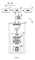
FIG. 1 is a block diagram illustrating a vehicle power window control system employing a ripple detection and motor position and speed determination routine according to one embodiment the present invention; -
FIG. 2 is a circuit/block diagram further illustrating the control system as shown inFIG. 1 ; -
FIG. 3 is a block diagram further illustrating the filter and ripple detection circuitry, according to a first embodiment; -
FIG. 4 is a block diagram illustrating the filter and ripple detection circuitry, according to a second embodiment; -
FIG. 5 is a circuit diagram illustrating a motor model, according to one embodiment; and -
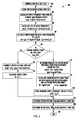
FIG. 6 is a flow diagram illustrating a routine for detecting ripple count and rotational position and speed of the motor, according to one embodiment of the present invention. - Referring now to
FIG. 1 , amotor control system 10 is generally illustrated for controlling a motor drivenpower window 16, according to one embodiment. The motor drivenpower window 16 may be employed onboard a vehicle, such as an automobile. Themotor control system 10 controls anelectric motor 14 responsive to user actuation of a switch (not shown) to actuate the window up (close) and down (open) and further monitors position and speed of themotor 14. Themotor control system 10 executes a motor position and speed detection withripple detection routine 100 and operates as a detection system to determine rotational position and speed of themotor 14. Themotor control system 10 is shown further having a windowanti-pinch routine 200 to prevent closing thewindow 16 on an object. It should be appreciated that themotor 14 may drive any of a number of actuated devices including, but not limited to, electric powered windows, sunroofs, seats, and other power devices. - The
motor 14 is a mechanically commutated direct current (DC) motor which receives electrical power from apower source 12 and has a motor with an output shaft that rotates to drive (actuate) the actuated device, such aspower window 16. Thecommutated DC motor 14 has an armature current signal Ia that generally includes a direct current (DC) component IDC and a ripple component IAC which occurs as a consequence of the magnetic field, the armature winding, and the commutator of theDC motor 14. Peaks in the current signal of the ripple component occur when the armature rotates, and the current ripple generally has a frequency corresponding to the number of commutator segments of the armature. Thus, the number of current ripples present in the current ripple component IAC indicates the rotational position of the armature of theDC motor 14 and may also be used to determine the speed of themotor 14. - The
control system 10 is further illustrated including acurrent sensor 18 and amicrocontroller 20. Thecurrent sensor 18 senses an electric current including the ripple component IAC of current in themotor 14. Additionally, voltage of themotor 14 may be input to themicrocontroller 20, and themicrocontroller 20 may provide control signals back to themotor 14 to control activation of themotor 14 and hence actuation of thewindow 16. Themicrocontroller 20 may include any control circuitry capable to processing sensed signals and routines, includingroutine 100 as described herein to detect current ripple and determine motor position and speed. According to one embodiment, themicrocontroller 20 includes amicroprocessor 22 andmemory 24.Memory 24 may include any volatile or non-volatile memory including, but not limited to, read-only memory (ROM), random access memory (RAM), electrically erasable programmable read-only memory (EEPROM), and flash memory. Stored withinmemory 24 are a plurality of routines including a motor position and speed detection andripple detection routine 100 for detecting current ripple and further determining position and speed of themotor 14, according to one embodiment of the present invention. Additionally, a windowanti-pinch routine 200 is also shown stored inmemory 24 for controlling the window so as to prevent closure when an obstruction is present. It should be appreciated thatroutine 200 may include a conventional anti-pinch routine and that other routines may be stored inmemory 24 and executed by themicroprocessor 22. It should further be included that themicrocontroller 20 may be a stand alone controller or may be integrated with other control circuitry. - The
microcontroller 20 controls the activation of themotor 14 responsive to a user input (not shown) such as a window switch. In doing so, electric current Ia passes through themotor 14 to rotate the armature and output shaft which in turn actuates thewindow 16. The current Ia includes the direct current component IDC and the ripple component IAC which is present when themotor 14 rotates. Thecurrent sensor 18 senses the current Ia including the ripple component IAC and inputs the sensed current Ia including the ripple current IAC to themicrocontroller 20 which, in turn, processes the sensed motor current including the detected ripples to determine an accurate ripple count, and further determines motor position and speed as explained herein. - Referring to
FIG. 2 , themotor control system 10 is further illustrated having apower source 12 supplying a DC voltage Va(t), such as twelve volts, to a direct current (DC)motor 14. The voltage Va(t) that is applied to themotor 14 is also input to an analog-to-digital (A/D) converter 40 in themicrocontroller 20 to convert the analog voltage to a digital voltage. Additionally, thecurrent sensor 18 senses the current Ia (t) passing through themotor 14 which is input to an analog-to-digital (A/D) converter 44 inmicrocontroller 20 to convert the analog current Ia (t) to a digital voltage representing the motor current. Thecurrent sensor 18 is shown made up of a resistor R andamplifier filter 42. Both the digital sensed voltage Va(n) and current Ia(n), which is represented as a sensed voltage, are input to amotor speed estimator 26 which also receives a motor constant Kb atblock 36. Themotor speed estimator 26 includes amotor model 28 that models the electrical characteristics of theDC motor 14. Themotor speed estimator 26 essentially estimates the rotational speed ωm of the motor, according to one embodiment. - The digital sensed current Ia is also input to a
dynamic bandpass filter 30 which filters the sensed current to filter out the DC current component IDC and to allow the AC portion of the current indicative of ripple events to pass therethrough as ripple current IAC which is input to aripple detector 32. Thedynamic bandpass filter 30 has a center frequency that is dynamically adapted to the motor ripple frequency, which enhances the ripple featuring both transient and steady state operating conditions. Theripple detector 32 performs an adaptive max-min function to detect ripple events. One example of a ripple detector performing a max-min function is disclosed inU.S. Patent Application Publication No. 2007/0075656 A1 , the entire disclosure of which is hereby incorporated herein by reference. The max-min function performs detection of the local maximum and minimum levels of the filtered motor ripple current IAC and the difference between the maximum and minimum levels is multiplied by a coefficient to form an adaptive threshold reference input to a comparator. - Included in
ripple detector 32 is a one-shot pulse generator 33 which also receives the estimated motor speed signal ωm(n). The filtered current waveform is compared with the reference input to generate a trigger to the one-shot generator 33 representing a ripple count. The period of the one-shot generator 33 is proportional to the ripple frequency, which adds dynamic blanking to mask extra pulses. Upon detection of a ripple event, a trigger is generated to the one-shot pulse generator 33 to mark the time point of commutation t(n). - The
ripple detector 32 outputs the time signal t(n) at which time ripple events are detected which are input to a pulse counter anderror correction block 34. The pulse counter anderror correction block 34 counts the number of pulses and evaluates the period fluctuation (ripple) of the motor current due to the commutation process and performs an error correction scheme based on an evaluation of the ripple count between successive frequency calculations using the present and previous time points of commutation (tn, tn-1, tn-2) and outputs a ripple count R. One example of a ripple detector that detects ripple and error is disclosed in European Patent Application No.EP 08003472, filed on February 26, 2008 speed determination block 35 which determines motor position θ and motor speed dθ /dt, both of which are provided as outputs. - The
dynamic bandpass filter 30 is further illustrated in more detail inFIG. 3 , according to a first embodiment.Filter 30 includes a ripple frequency andmotor state block 50 for receiving the estimated motor rotational speed ωm and providing the ripple frequency and motor state as outputs toblocks Block 52 multiplies the ripple frequency by a constant a1, whileblock 56 multiplies the ripple frequency by a constant a2. Constant a1 represents the index for selection of the high pass filter coefficients infilters low pass filter 58 coefficients so that the cut-off frequency is a percentage below the ripple frequency. The output ofblock 52 is provided along with the digital sensed current Ia to aDC blocking filter 54 which filters out the DC current component such that the AC current IAC with ripple signals pass therethrough. The output ofDC blocking filter 54 is input to alow pass filter 58 along with the output ofblock 56 to provide the filtered AC component of the ripple current IAC. - The
dynamic bandpass filter 30 may alternately be implemented as shown inFIG. 4 , according to a second embodiment. In this embodiment, the output ofblock 52 is provided as an input to alow pass filter 58, and the output ofblock 56 is input to anotherlow pass filter 58. The difference between the outputs of the low pass filters 58 is computed in summingblock 60, and the difference output provides for the filtered AC component of ripple current IAC. - When the
control system 20 determines that it is probable that ripple detection error has occurred, it switches to amotor state model 28, shown in one embodiment provided in themotor speed estimator 26. Themotor model 28 uses a speed dependent motor voltage Vb to estimate the ripple frequency, where a ratio based on the motor model estimate of the ripple frequency and the actual calculated ripple frequency are evaluated to determine the number of ripple counts that should have been detected. The circuit shown inFIG. 5 represents amotor model 28, according to one embodiment. The speed and rotational position of the DC motor can be calculated from the measured armature voltage and current estimated with knowledge of the motor constants using electro-mechanical equations of a DC motor. The motor armature is modelled electrically as a series circuit combination of inductance La and resistance Ra and a speed dependent voltage source Vb. The mechanical portion of the model includes a rotating mass with moment of inertia Jm and a viscous damping force Bm. Motor torque Tm may be represented by a torque constant Kt multiplied by the armature current Ia. The back EMF voltage Vb may be equal to the product of the electrical back EMF constant Kb and the rotational velocity ω m . Using the simplified motor electrical equation, where inductance of the armature La is assumed to be zero, the motor rotational velocity ω m may be represented by:
- The commutation ripple frequency in hertz can be calculated by the following equation:

- Where n is speed (revs/min) and N represents the number of commutations per revolution of the motor. The commutation ripple frequency is essentially equal to the frequency of the motor multiplied by the number of commutations per revolution.
- The
control system 10 andmethod 100 of the present invention advantageously determine the ripple count and provide for error correction in a manner that is efficient and robust. In doing so, the AC current signal IAC is extracted from the DC component IDC of the current signal Ia to get sufficient resolution of the ripples. The AC current signal IAC is separated from the DC portion of the current signal using the dynamic bandpass filter whose center frequency is dynamically adapted to the motor ripple frequency fR . This significantly enhances the ripple feature during both transient and steady state operations. Upon detection of a ripple event, a trigger is generated by the one-shot pulse generator to mark the time point of commutation tn. It should be appreciated that errors may arise due to limitations in the commutation ripple detection method, noise on the supply line from other loads, or from distortion in the ripple waveform due to motor parameter variation or the state of operation, such as starting, braking, assist load or stall condition. The method and system of the present invention advantageously corrects for such errors in the ripple count. - Referring to
FIG. 6 , the motor position and speed detection withripple detection routine 100 is illustrated, according to one embodiment.Routine 100 determines the ripple count and further determines the position of the motor and the speed of the motor.Routine 100 begins atstep 102 to detect each commutation pulse of the motor. Next, instep 104, the time of the commutation event is marked. Next, the ripple frequency fR (n) is calculated from the time of the current event t(n) and the previous events t(n-1) as shown instep 106. The frequency of the ripple fR is generally equal to 1 divided by dt, where dt is the time between the ripples. - Proceeding to step 108, routine 100 calculates the time between successive calculated frequencies, shown as dtf(n). The time between successive calculated frequencies is determined by first calculating ripple frequency from the current event n at time t(n) and the previous event n-1 at time t(n-1), and the ripple frequency calculated from the previous time event t(n-1) and the next prior event t(n-2). Next, the ripple count R between the two frequencies is calculated in
step 110. The ripple count R is computed as the integral of fRdt, such that the change in the ripple count dR between the two successive frequencies can be computed as shown by the equation inblock 110. Indecision step 114, the change in ripple count dR is compared to a threshold value shown as maximum limit (e.g., 1.05). It should be appreciated that if the ripple timing is correct, the result of the pulse count should result in dR being close to 1.00, such that dR is between 0.95 and 1.05 and the ripple count is incremented. Other threshold value may be employed according to other embodiments. If the change in ripple count dR is not greater than the maximum limit, then routine 100 proceeds to calibrate the motor voltage constant Kb(n) instep 122, and then increments the pulse count R = R+1 instep 124. - If the ripple count error dR is determined to be greater than the maximum limit of 1.05 in
step 114, routine 100 proceeds to step 116 to determine a probable estimated ripple frequency from the speed dependent motor voltage. The estimated ripple frequency determination from the speed dependent motor voltage is achieved by switching to use of the motor model, such that the ratio of the motor state model estimate of the ripple frequency and the actual calculated ripple frequency are evaluated to determine the number of ripple counts that should have been detected. Next, routine 100 calculates the corrected ripple count from the ratio of the calculated ripple frequency and the estimated ripple frequency instep 118, and then stores the probable ripple frequency for the next cycle instep 120. Given the calculated corrected pulse count R, routine 100 may then proceed to step 126 to determine the motor angular position θ based on the ripple count. Additionally, routine 100 may proceed to step 128 to determine motor angular speed dθ /dt based on the ripple count. Thereafter, routine 100 ends atstep 130. It should be appreciated that routine 100 may be periodically repeated or that it may automatically return to the beginning atstep 102 followingstep 130. - Accordingly, the
control system 10 and routine 100 advantageously determines ripple count of a mechanically commutated DC motor and efficiently corrects for error in the ripple count to provide for an accurate ripple count. This enables the accurate determination of motor position and motor speed. - It will be understood by those who practice the invention and those skilled in the art, that various modifications and improvements may be made to the invention without departing from the spirit of the disclosed concept. The scope of protection afforded is to be determined by the claims and by the breadth of interpretation allowed by law.
Claims (15)
- A method (100) for determining ripple count of a mechanically commutated DC motor (14) from the motor current ripple due to commutation, said method comprising the steps of:monitoring motor current (Ia) of a mechanically commutated DC motor (14);detecting (102) ripples in the motor current (Ia);calculating (106) a ripple frequency based on time between two successive ripples;determining (110) a ripple count between two successive frequencies;comparing (114) the ripple count to a threshold value;determining (116) an estimated ripple frequency from a motor model (28) when the ripple count exceeds the threshold value; andcalculating (118) a corrected ripple count from a ratio of the calculated ripple frequency and the estimated ripple frequency.
- The method as defined in claim 1, further comprising the step of determining (126) at least one of motor position and motor speed based on the corrected ripple count.
- The method as defined in claim 1 or 2, wherein the step of detecting (102) ripples comprises comparing the motor current to a dynamic threshold, wherein the dynamic threshold is a percentage difference between local maximum and minimum values of motor current.
- The method as defined in claim 1 or 2, wherein the motor model calculates an estimated motor speed, and wherein the estimated ripple frequency is estimated based on the motor speed.
- The method as defined in claim 4, wherein the method further compares the ratio of the calculated ripple frequency and the estimated ripple frequency to determine the number of ripple counts that should have been detected.
- The method as defined in claim 1 or 2, wherein the motor model is a speed dependent motor voltage.
- The method as defined in claim 1 or 2 further comprising the step of calculating (108) a time between two frequencies, wherein the ripple count is determined based on the calculated time.
- A detection system (10) for determining ripple count of a mechanically commutated DC motor (14) from motor current ripple due to commutation, said system comprising;
a current sensor (18) for sensing current (Ia) of a mechanically commutated DC motor (14); and
a processor (22) for processing the sensed motor current to detect a motor ripple count and determining at least one of rotational position and speed of the motor (14), said processor (22) detecting ripples in the sensed motor current, calculating a ripple frequency based on time between two successive ripples, determining a ripple count between two successive frequencies, comparing the ripple count to a threshold value, determining an estimated ripple frequency from a motor model when the ripple count exceeds the threshold value, and calculating a corrected ripple count from a ratio of the calculated ripple frequency and the estimated ripple frequency. - A detection system as defined in claim 8, wherein the processor (22) also determines at least one of motor position and motor speed based on the corrected ripple count.
- The detection system as defined in claim 8 or 9, wherein said processor (22) detecting ripples includes comparing the motor current to a dynamic threshold, wherein the dynamic threshold is a percentage difference between local maximum and minimum values of motor current.
- The detection system as defined in claim 8 or 9, wherein the motor model (28) calculates an estimated motor speed, and wherein the estimated ripple frequency is estimated based on the estimated motor speed.
- The detection system as defined in claim 11, wherein the processor (22) further compares the ratio of the calculated ripple frequency and the estimated ripple frequency to determine the number of ripple counts that should have been detected.
- The detection system as defined in claim 8 or 9, wherein the motor model (28) is a speed dependent motor voltage.
- The detection system as defined in claim 8 or 9, wherein the processor (22) further calculates a time between two frequencies, wherein the ripple count is determined based on the calculated time.
- The detection system as defined in any one of claims 8 to 14, wherein the motor (14) is employed to drive a window (16).
Applications Claiming Priority (2)
| Application Number | Priority Date | Filing Date | Title |
|---|---|---|---|
| US4326608P | 2008-04-08 | 2008-04-08 | |
| US12/152,302 US7668690B2 (en) | 2008-04-08 | 2008-05-14 | System and method for determining position or speed of a commutated DC motor with error correction |
Publications (2)
| Publication Number | Publication Date |
|---|---|
| EP2109211A1 true EP2109211A1 (en) | 2009-10-14 |
| EP2109211B1 EP2109211B1 (en) | 2011-06-01 |
Family
ID=40791619
Family Applications (1)
| Application Number | Title | Priority Date | Filing Date |
|---|---|---|---|
| EP09156014A Active EP2109211B1 (en) | 2008-04-08 | 2009-03-24 | System and method for determining position or speed of a commutaded DC motor with error correction |
Country Status (3)
| Country | Link |
|---|---|
| US (1) | US7668690B2 (en) |
| EP (1) | EP2109211B1 (en) |
| AT (1) | ATE511713T1 (en) |
Cited By (7)
| Publication number | Priority date | Publication date | Assignee | Title |
|---|---|---|---|---|
| ES2334551A1 (en) * | 2009-11-05 | 2010-03-11 | Universidad De Valladolid (Miguel San Jose Daniel) | METHOD FOR DETERMINING ANGLE SPEED IN A MECHANICALLY COMMITTED ENGINE BY ONLY MAKING THE CURRENT CIRCULATING THEMSELVES. |
| WO2014089255A3 (en) * | 2012-12-05 | 2014-12-18 | Gojo Industries, Inc. | Adaptable sensorless end of stroke detection system and method |
| WO2015028477A1 (en) * | 2013-08-27 | 2015-03-05 | Borgwarner Torqtransfer Systems Ab | A vehicle system, and a method for such vehicle system |
| FR3033218A1 (en) * | 2015-02-27 | 2016-09-02 | Hamilton Sundstrand Corp | |
| CN108061511A (en) * | 2017-12-11 | 2018-05-22 | 北京经纬恒润科技有限公司 | The computational methods and device of a kind of position |
| DE102019211800A1 (en) * | 2019-08-06 | 2021-02-11 | Conti Temic Microelectronic Gmbh | Method and device for determining the speed and the angle of rotation of a motor shaft of a mechanically commutated direct current motor |
| EP4329184A1 (en) * | 2022-08-23 | 2024-02-28 | HELLA GmbH & Co. KGaA | System and method for ripple count detection |
Families Citing this family (46)
| Publication number | Priority date | Publication date | Assignee | Title |
|---|---|---|---|---|
| JP2007205092A (en) * | 2006-02-03 | 2007-08-16 | Tachibana Eletech Co Ltd | Signal input method and opening/closing control device |
| JP5111912B2 (en) * | 2006-05-10 | 2013-01-09 | 株式会社リコー | Motor drive device and image forming apparatus |
| GB0713239D0 (en) * | 2007-07-07 | 2007-08-15 | Trw Ltd | Electriv motor control |
| US20100039057A1 (en) * | 2008-04-30 | 2010-02-18 | Tsai Kune-Muh | Anti-pinch method and device for controlling an openable and closable body |
| DE102008041307A1 (en) * | 2008-08-18 | 2010-02-25 | Robert Bosch Gmbh | Method for dynamically adjusting an angular velocity with a digital angle sensor |
| WO2012086555A1 (en) * | 2010-12-24 | 2012-06-28 | 株式会社リブ技術研究所 | Trapping determination device for opening/closing section, vehicle with same, and trapping determination method for opening/closing section |
| EP2482442B2 (en) * | 2011-01-27 | 2021-02-24 | ebm-papst Mulfingen GmbH & Co. KG | Method and control system for controlling a brushless electric motor |
| JP5882919B2 (en) * | 2011-02-10 | 2016-03-09 | 株式会社マキタ | Device and power tool for estimating state quantity related to motor |
| US9000710B2 (en) * | 2011-06-22 | 2015-04-07 | Lexmark International, Inc. | Method and apparatus for measuring speed of a brush motor |
| US8896248B2 (en) * | 2011-07-27 | 2014-11-25 | Regal Beloit America, Inc. | Methods and systems for controlling a motor |
| US20130113457A1 (en) * | 2011-11-04 | 2013-05-09 | Kohler Co. | Method of sensing generator speed |
| US20140052346A1 (en) * | 2012-08-17 | 2014-02-20 | Ford Global Technologies, Llc | Soft start window regulator |
| US9024547B2 (en) * | 2012-09-28 | 2015-05-05 | Allied Telesis, Inc. | Fan conducted noise reduction |
| KR101993656B1 (en) * | 2012-11-16 | 2019-06-26 | 휴렛-팩커드 디벨롭먼트 컴퍼니, 엘.피. | Image forming apparatus and method of controlling the same, motor state detector |
| DE102013015119A1 (en) * | 2013-09-12 | 2015-03-12 | Brose Fahrzeugteile Gmbh & Co. Kommanditgesellschaft, Hallstadt | Adjusting device for adjusting a vehicle between an adjustable position and an open position adjustable vehicle part |
| EP3102959A4 (en) * | 2014-02-07 | 2017-10-04 | Nidec Motor Corporation | Systems, devices, and methods for motor monitoring |
| CN105083057A (en) * | 2014-04-25 | 2015-11-25 | 德昌电机(深圳)有限公司 | Seat position adjusting system and method |
| CN105099298A (en) * | 2014-04-25 | 2015-11-25 | 德昌电机(深圳)有限公司 | Movable part control device and method and motor ripple signal processing circuit |
| US9859826B2 (en) | 2016-02-03 | 2018-01-02 | Infineon Technologies Ag | Intelligent detection unit (iDU) to detect the position of a rotor controlled by pulse modulation |
| JP2018023238A (en) * | 2016-08-05 | 2018-02-08 | オムロン株式会社 | Evaluation system, evaluation apparatus, gaming machine and evaluation method |
| JP6665070B2 (en) * | 2016-10-25 | 2020-03-13 | 株式会社ミツバ | Motor control device and method for detecting current ripple of DC motor |
| BR112019007415B1 (en) | 2016-10-31 | 2021-06-22 | Kimberly-Clark Worldwide, Inc | CONTROL METHOD FOR AN ELECTRONIC LIQUID DISPENSER, AND, ELECTRONIC LIQUID DISPENSER. |
| US10322746B2 (en) | 2016-11-30 | 2019-06-18 | Steering Solutions Ip Holding Corporation | Velocity estimation for electric power steering systems |
| WO2018199104A1 (en) * | 2017-04-27 | 2018-11-01 | アルプス電気株式会社 | Electric motor with rotation angle detector, electric motor rotation angle detector, and method for detecting rotation angle of electric motor equipped with commutator |
| US10340828B2 (en) * | 2017-04-27 | 2019-07-02 | Steering Solutions Ip Holding Corporation | Disturbance observer for permanent magnet direct current machines |
| US20180367073A1 (en) * | 2017-06-14 | 2018-12-20 | Allegro Microsystems, Llc | Motor control circuit with diagnostic capabilities |
| NL2019723B1 (en) * | 2017-10-13 | 2019-04-23 | Mci Mirror Controls Int Netherlands B V | Method and device for providing information on an annular displacement of a DC electromotor |
| WO2019074370A2 (en) * | 2017-10-13 | 2019-04-18 | Mci (Mirror Controls International Netherlands B.V | Method and device for providing information on an annular displacement of a dc electromotor |
| FR3076678B1 (en) * | 2018-01-09 | 2020-11-27 | Inteva Products France Sas | CASCADE COUNTING CIRCUIT |
| DE102019132913A1 (en) * | 2018-12-06 | 2020-06-10 | Magna Closures Inc. | WAVE COUNTING FILTERING AND METHOD AND SYSTEM FOR DETECTING PEAK VALUES |
| JPWO2020129922A1 (en) * | 2018-12-17 | 2021-09-30 | 株式会社デンソー | DC motor |
| EP3723271B1 (en) * | 2019-04-12 | 2023-10-25 | Aptiv Technologies Limited | Method for determining a movement of a rotor of an electric motor and control system for an electric motor |
| US11218096B2 (en) | 2019-11-29 | 2022-01-04 | Steering Solutions Ip Holding Corporation | Feedforward control of multiphase permanent magnet direct current motor drives |
| CN111098808B (en) * | 2019-12-12 | 2022-06-07 | 北京经纬恒润科技股份有限公司 | Method and system for controlling vehicle body closed part based on direct current motor ripple |
| CN111361468A (en) * | 2020-03-25 | 2020-07-03 | 浙江航芯科技有限公司 | Anti-pinch control circuit and method for memory seat of automobile |
| US11844432B2 (en) | 2020-03-27 | 2023-12-19 | La-Z-Boy Incorporated | Furniture motion control system |
| US11711034B2 (en) | 2020-12-01 | 2023-07-25 | Kohler Co. | Sensorless position detection for electric machine |
| FR3121806B1 (en) * | 2021-04-09 | 2023-08-04 | Inteva Products Llc | INTERFERENCE PULSE CANCELLATION CIRCUIT |
| FR3121805A1 (en) * | 2021-04-09 | 2022-10-14 | Inteva Products, Llc. | INTERFERENCE PULSE CANCELLATION CIRCUIT |
| CH718623A2 (en) * | 2021-05-12 | 2022-11-15 | Oblamatik Ag | Adjustment device, motor-driven valve and method for operating an adjustment device. |
| JP7772464B2 (en) * | 2022-03-01 | 2025-11-18 | アルプスアルパイン株式会社 | Rotation angle detection device and rotation angle detection method |
| US12203822B2 (en) | 2022-04-14 | 2025-01-21 | Allegro Microsystems, Llc | Heterogeneous magnetic and inductive sensors |
| US12460915B2 (en) * | 2022-05-31 | 2025-11-04 | Renesas Electronics Corporation | Angle error correction device |
| US20240128901A1 (en) * | 2022-10-13 | 2024-04-18 | Texas Instruments Incorporated | Single chip advanced adaptive sensorless motor shaft position detection |
| CN117129705B (en) * | 2023-10-25 | 2024-07-02 | 成都维客昕微电子有限公司 | Motor rotating speed detection system and method based on working current |
| US12455178B2 (en) | 2023-12-22 | 2025-10-28 | Allegro Microsystems, Llc | Inductive linear stroke sensor using dual tracks with different periodicity |
Citations (6)
| Publication number | Priority date | Publication date | Assignee | Title |
|---|---|---|---|---|
| DE10124615A1 (en) * | 2001-05-21 | 2002-12-05 | Kostal Leopold Gmbh & Co Kg | Method for correcting a determination of the rotational position of a drive shaft of a commutated direct current motor |
| US20040027264A1 (en) * | 2000-06-06 | 2004-02-12 | Stefan Otte | Method for providing a digital current fluctuation signal |
| US20040107071A1 (en) * | 2001-05-30 | 2004-06-03 | Leopold Kostal Gmbh & Co. Kg | Method for determining the rotational position of the drive shaft of a commutated DC motor |
| DE202004010211U1 (en) * | 2004-06-30 | 2005-08-18 | Brose Fahrzeugteile Gmbh & Co. Kommanditgesellschaft, Coburg | Control device for controlling an adjusting device of a motor vehicle |
| EP1659683A1 (en) * | 2004-11-23 | 2006-05-24 | Robert Bosch Gmbh | Method and apparatus for determining the AC component of a current produced by the mechanical commutation of a DC motor |
| US20070075656A1 (en) | 2005-10-04 | 2007-04-05 | Moller David D | Position detection and external driver multiplexing system for DC motors |
Family Cites Families (5)
| Publication number | Priority date | Publication date | Assignee | Title |
|---|---|---|---|---|
| US5497326A (en) | 1994-08-03 | 1996-03-05 | The Cherry Corporation | Intelligent commutation pulse detection system to control electric D.C. motors used with automobile accessories |
| DE19729238C1 (en) | 1997-07-09 | 1998-08-27 | Telefunken Microelectron | Speed determining method for mechanically commutated DC motors |
| JP4433547B2 (en) * | 2000-02-29 | 2010-03-17 | アイシン精機株式会社 | Motor rotation pulse generator |
| JP4655400B2 (en) * | 2000-05-30 | 2011-03-23 | アイシン精機株式会社 | Motor rotation pulse generation circuit for DC motor |
| DE10126167A1 (en) * | 2001-05-30 | 2002-12-05 | Kostal Leopold Gmbh & Co Kg | Method for correcting a rotational position determination of a drive shaft of a commutated direct current motor |
-
2008
- 2008-05-14 US US12/152,302 patent/US7668690B2/en active Active
-
2009
- 2009-03-24 AT AT09156014T patent/ATE511713T1/en not_active IP Right Cessation
- 2009-03-24 EP EP09156014A patent/EP2109211B1/en active Active
Patent Citations (6)
| Publication number | Priority date | Publication date | Assignee | Title |
|---|---|---|---|---|
| US20040027264A1 (en) * | 2000-06-06 | 2004-02-12 | Stefan Otte | Method for providing a digital current fluctuation signal |
| DE10124615A1 (en) * | 2001-05-21 | 2002-12-05 | Kostal Leopold Gmbh & Co Kg | Method for correcting a determination of the rotational position of a drive shaft of a commutated direct current motor |
| US20040107071A1 (en) * | 2001-05-30 | 2004-06-03 | Leopold Kostal Gmbh & Co. Kg | Method for determining the rotational position of the drive shaft of a commutated DC motor |
| DE202004010211U1 (en) * | 2004-06-30 | 2005-08-18 | Brose Fahrzeugteile Gmbh & Co. Kommanditgesellschaft, Coburg | Control device for controlling an adjusting device of a motor vehicle |
| EP1659683A1 (en) * | 2004-11-23 | 2006-05-24 | Robert Bosch Gmbh | Method and apparatus for determining the AC component of a current produced by the mechanical commutation of a DC motor |
| US20070075656A1 (en) | 2005-10-04 | 2007-04-05 | Moller David D | Position detection and external driver multiplexing system for DC motors |
Cited By (13)
| Publication number | Priority date | Publication date | Assignee | Title |
|---|---|---|---|---|
| ES2334551B1 (en) * | 2009-11-05 | 2011-02-07 | Universidad De Valladolid | METHOD FOR DETERMINING ANGLE SPEED IN A MECHANICALLY COMMITTED ENGINE ONLY MAKING THE CURRENT CIRCULATING THEMSELVES. |
| ES2334551A1 (en) * | 2009-11-05 | 2010-03-11 | Universidad De Valladolid (Miguel San Jose Daniel) | METHOD FOR DETERMINING ANGLE SPEED IN A MECHANICALLY COMMITTED ENGINE BY ONLY MAKING THE CURRENT CIRCULATING THEMSELVES. |
| WO2014089255A3 (en) * | 2012-12-05 | 2014-12-18 | Gojo Industries, Inc. | Adaptable sensorless end of stroke detection system and method |
| US9211041B2 (en) | 2012-12-05 | 2015-12-15 | Gojo Industries, Inc. | Adaptable sensorless end of stroke detection system and method |
| WO2015028477A1 (en) * | 2013-08-27 | 2015-03-05 | Borgwarner Torqtransfer Systems Ab | A vehicle system, and a method for such vehicle system |
| US10281500B2 (en) | 2015-02-27 | 2019-05-07 | Hamilton Sundstrand Corporation | Digitally implemented ripple detector |
| FR3033218A1 (en) * | 2015-02-27 | 2016-09-02 | Hamilton Sundstrand Corp | |
| CN108061511A (en) * | 2017-12-11 | 2018-05-22 | 北京经纬恒润科技有限公司 | The computational methods and device of a kind of position |
| CN108061511B (en) * | 2017-12-11 | 2019-08-30 | 北京经纬恒润科技有限公司 | A kind of calculation method and device of position |
| DE102019211800A1 (en) * | 2019-08-06 | 2021-02-11 | Conti Temic Microelectronic Gmbh | Method and device for determining the speed and the angle of rotation of a motor shaft of a mechanically commutated direct current motor |
| US11283380B2 (en) | 2019-08-06 | 2022-03-22 | Conti Temic Microelectronic Gmbh | Method and device for determining the rotational speed and the angle of rotation of a motor shaft of a mechanically commutated DC motor |
| DE102019211800B4 (en) | 2019-08-06 | 2022-12-15 | Conti Temic Microelectronic Gmbh | Method and device for determining the speed and the angle of rotation of a motor shaft of a mechanically commutated DC motor |
| EP4329184A1 (en) * | 2022-08-23 | 2024-02-28 | HELLA GmbH & Co. KGaA | System and method for ripple count detection |
Also Published As
| Publication number | Publication date |
|---|---|
| US7668690B2 (en) | 2010-02-23 |
| ATE511713T1 (en) | 2011-06-15 |
| US20090254300A1 (en) | 2009-10-08 |
| EP2109211B1 (en) | 2011-06-01 |
Similar Documents
| Publication | Publication Date | Title |
|---|---|---|
| EP2109211B1 (en) | System and method for determining position or speed of a commutaded DC motor with error correction | |
| US8310185B2 (en) | Correction of counting errors in the evaluation of current ripples in a DC motor | |
| EP0219290B1 (en) | Torque control apparatus for rotary machine | |
| US6426604B1 (en) | Power window controlling device | |
| EP1484834B9 (en) | Rotor position detection of a switched reluctance drive | |
| CN102835021B (en) | Handling Motor Variables for DC Motors | |
| US6236175B1 (en) | Process and device for detecting the speed of rotation of a DC electric motor controlled by a PWM control signal | |
| EP2151917A2 (en) | Method for controlling a two-phase d.c. brushless motor without a position sensor | |
| EP1324484B1 (en) | Rotor position detection of a switched reluctance device | |
| JP4352446B2 (en) | Drive apparatus and method for adjusting vehicle parts | |
| EP3263817A1 (en) | Opening/closing control device | |
| JP2760267B2 (en) | Motor drive | |
| US8138701B2 (en) | Method for determining the position of a rotor of an electric motor without sensors | |
| US6845337B2 (en) | Method for correcting the determination of the rotating position of a drive shaft of a commutated direct current motor | |
| EP3136583A1 (en) | Brushless motor drive device | |
| US20100315032A1 (en) | Method for determining the angular position of the rotor of a mechanically commutated dc servo motor | |
| US20130057187A1 (en) | Method and device for detecting blocking or sluggishness of a dc motor | |
| US7294981B2 (en) | Method of determining the position of the shaft of a drive motor for a roller blind | |
| KR101857936B1 (en) | Method for detecting blockages of electrically commutated electric motors | |
| US8022653B2 (en) | Method and circuit arrangement for the electrical control and/or regulation of the movement of an electrically driven unit | |
| EP4329184A1 (en) | System and method for ripple count detection | |
| JP3555226B2 (en) | Moving object position detection device | |
| KR20140048581A (en) | Device for detecting error of sensorless motor using bemf signal | |
| WO2005062456A1 (en) | Detecting a failure in a converter-load system | |
| CN111817621B (en) | Method for determining the motion of the rotor |
Legal Events
| Date | Code | Title | Description |
|---|---|---|---|
| PUAI | Public reference made under article 153(3) epc to a published international application that has entered the european phase |
Free format text: ORIGINAL CODE: 0009012 |
|
| AK | Designated contracting states |
Kind code of ref document: A1 Designated state(s): AT BE BG CH CY CZ DE DK EE ES FI FR GB GR HR HU IE IS IT LI LT LU LV MC MK MT NL NO PL PT RO SE SI SK TR |
|
| AX | Request for extension of the european patent |
Extension state: AL BA RS |
|
| 17P | Request for examination filed |
Effective date: 20100414 |
|
| 17Q | First examination report despatched |
Effective date: 20100510 |
|
| AKX | Designation fees paid |
Designated state(s): AT BE BG CH CY CZ DE DK EE ES FI FR GB GR HR HU IE IS IT LI LT LU LV MC MK MT NL NO PL PT RO SE SI SK TR |
|
| GRAP | Despatch of communication of intention to grant a patent |
Free format text: ORIGINAL CODE: EPIDOSNIGR1 |
|
| GRAS | Grant fee paid |
Free format text: ORIGINAL CODE: EPIDOSNIGR3 |
|
| GRAA | (expected) grant |
Free format text: ORIGINAL CODE: 0009210 |
|
| AK | Designated contracting states |
Kind code of ref document: B1 Designated state(s): AT BE BG CH CY CZ DE DK EE ES FI FR GB GR HR HU IE IS IT LI LT LU LV MC MK MT NL NO PL PT RO SE SI SK TR |
|
| REG | Reference to a national code |
Ref country code: GB Ref legal event code: FG4D |
|
| REG | Reference to a national code |
Ref country code: CH Ref legal event code: EP |
|
| REG | Reference to a national code |
Ref country code: IE Ref legal event code: FG4D |
|
| REG | Reference to a national code |
Ref country code: DE Ref legal event code: R096 Ref document number: 602009001412 Country of ref document: DE Effective date: 20110714 |
|
| REG | Reference to a national code |
Ref country code: NL Ref legal event code: VDEP Effective date: 20110601 |
|
| PG25 | Lapsed in a contracting state [announced via postgrant information from national office to epo] |
Ref country code: NO Free format text: LAPSE BECAUSE OF FAILURE TO SUBMIT A TRANSLATION OF THE DESCRIPTION OR TO PAY THE FEE WITHIN THE PRESCRIBED TIME-LIMIT Effective date: 20110901 Ref country code: SE Free format text: LAPSE BECAUSE OF FAILURE TO SUBMIT A TRANSLATION OF THE DESCRIPTION OR TO PAY THE FEE WITHIN THE PRESCRIBED TIME-LIMIT Effective date: 20110601 Ref country code: HR Free format text: LAPSE BECAUSE OF FAILURE TO SUBMIT A TRANSLATION OF THE DESCRIPTION OR TO PAY THE FEE WITHIN THE PRESCRIBED TIME-LIMIT Effective date: 20110601 Ref country code: LT Free format text: LAPSE BECAUSE OF FAILURE TO SUBMIT A TRANSLATION OF THE DESCRIPTION OR TO PAY THE FEE WITHIN THE PRESCRIBED TIME-LIMIT Effective date: 20110601 |
|
| PG25 | Lapsed in a contracting state [announced via postgrant information from national office to epo] |
Ref country code: LV Free format text: LAPSE BECAUSE OF FAILURE TO SUBMIT A TRANSLATION OF THE DESCRIPTION OR TO PAY THE FEE WITHIN THE PRESCRIBED TIME-LIMIT Effective date: 20110601 Ref country code: AT Free format text: LAPSE BECAUSE OF FAILURE TO SUBMIT A TRANSLATION OF THE DESCRIPTION OR TO PAY THE FEE WITHIN THE PRESCRIBED TIME-LIMIT Effective date: 20110601 Ref country code: FI Free format text: LAPSE BECAUSE OF FAILURE TO SUBMIT A TRANSLATION OF THE DESCRIPTION OR TO PAY THE FEE WITHIN THE PRESCRIBED TIME-LIMIT Effective date: 20110601 Ref country code: CY Free format text: LAPSE BECAUSE OF FAILURE TO SUBMIT A TRANSLATION OF THE DESCRIPTION OR TO PAY THE FEE WITHIN THE PRESCRIBED TIME-LIMIT Effective date: 20110601 Ref country code: SI Free format text: LAPSE BECAUSE OF FAILURE TO SUBMIT A TRANSLATION OF THE DESCRIPTION OR TO PAY THE FEE WITHIN THE PRESCRIBED TIME-LIMIT Effective date: 20110601 Ref country code: ES Free format text: LAPSE BECAUSE OF FAILURE TO SUBMIT A TRANSLATION OF THE DESCRIPTION OR TO PAY THE FEE WITHIN THE PRESCRIBED TIME-LIMIT Effective date: 20110912 |
|
| PG25 | Lapsed in a contracting state [announced via postgrant information from national office to epo] |
Ref country code: NL Free format text: LAPSE BECAUSE OF FAILURE TO SUBMIT A TRANSLATION OF THE DESCRIPTION OR TO PAY THE FEE WITHIN THE PRESCRIBED TIME-LIMIT Effective date: 20110601 Ref country code: BE Free format text: LAPSE BECAUSE OF FAILURE TO SUBMIT A TRANSLATION OF THE DESCRIPTION OR TO PAY THE FEE WITHIN THE PRESCRIBED TIME-LIMIT Effective date: 20110601 |
|
| PG25 | Lapsed in a contracting state [announced via postgrant information from national office to epo] |
Ref country code: PT Free format text: LAPSE BECAUSE OF FAILURE TO SUBMIT A TRANSLATION OF THE DESCRIPTION OR TO PAY THE FEE WITHIN THE PRESCRIBED TIME-LIMIT Effective date: 20111003 Ref country code: IS Free format text: LAPSE BECAUSE OF FAILURE TO SUBMIT A TRANSLATION OF THE DESCRIPTION OR TO PAY THE FEE WITHIN THE PRESCRIBED TIME-LIMIT Effective date: 20111001 Ref country code: CZ Free format text: LAPSE BECAUSE OF FAILURE TO SUBMIT A TRANSLATION OF THE DESCRIPTION OR TO PAY THE FEE WITHIN THE PRESCRIBED TIME-LIMIT Effective date: 20110601 Ref country code: EE Free format text: LAPSE BECAUSE OF FAILURE TO SUBMIT A TRANSLATION OF THE DESCRIPTION OR TO PAY THE FEE WITHIN THE PRESCRIBED TIME-LIMIT Effective date: 20110601 |
|
| PG25 | Lapsed in a contracting state [announced via postgrant information from national office to epo] |
Ref country code: PL Free format text: LAPSE BECAUSE OF FAILURE TO SUBMIT A TRANSLATION OF THE DESCRIPTION OR TO PAY THE FEE WITHIN THE PRESCRIBED TIME-LIMIT Effective date: 20110601 Ref country code: SK Free format text: LAPSE BECAUSE OF FAILURE TO SUBMIT A TRANSLATION OF THE DESCRIPTION OR TO PAY THE FEE WITHIN THE PRESCRIBED TIME-LIMIT Effective date: 20110601 |
|
| PLBE | No opposition filed within time limit |
Free format text: ORIGINAL CODE: 0009261 |
|
| STAA | Information on the status of an ep patent application or granted ep patent |
Free format text: STATUS: NO OPPOSITION FILED WITHIN TIME LIMIT |
|
| 26N | No opposition filed |
Effective date: 20120302 |
|
| REG | Reference to a national code |
Ref country code: DE Ref legal event code: R097 Ref document number: 602009001412 Country of ref document: DE Effective date: 20120302 |
|
| PG25 | Lapsed in a contracting state [announced via postgrant information from national office to epo] |
Ref country code: DK Free format text: LAPSE BECAUSE OF FAILURE TO SUBMIT A TRANSLATION OF THE DESCRIPTION OR TO PAY THE FEE WITHIN THE PRESCRIBED TIME-LIMIT Effective date: 20110601 |
|
| PG25 | Lapsed in a contracting state [announced via postgrant information from national office to epo] |
Ref country code: MC Free format text: LAPSE BECAUSE OF NON-PAYMENT OF DUE FEES Effective date: 20120331 |
|
| REG | Reference to a national code |
Ref country code: IE Ref legal event code: MM4A |
|
| PG25 | Lapsed in a contracting state [announced via postgrant information from national office to epo] |
Ref country code: IE Free format text: LAPSE BECAUSE OF NON-PAYMENT OF DUE FEES Effective date: 20120324 |
|
| PG25 | Lapsed in a contracting state [announced via postgrant information from national office to epo] |
Ref country code: MK Free format text: LAPSE BECAUSE OF FAILURE TO SUBMIT A TRANSLATION OF THE DESCRIPTION OR TO PAY THE FEE WITHIN THE PRESCRIBED TIME-LIMIT Effective date: 20110601 |
|
| PG25 | Lapsed in a contracting state [announced via postgrant information from national office to epo] |
Ref country code: BG Free format text: LAPSE BECAUSE OF FAILURE TO SUBMIT A TRANSLATION OF THE DESCRIPTION OR TO PAY THE FEE WITHIN THE PRESCRIBED TIME-LIMIT Effective date: 20110901 |
|
| PG25 | Lapsed in a contracting state [announced via postgrant information from national office to epo] |
Ref country code: MT Free format text: LAPSE BECAUSE OF FAILURE TO SUBMIT A TRANSLATION OF THE DESCRIPTION OR TO PAY THE FEE WITHIN THE PRESCRIBED TIME-LIMIT Effective date: 20110601 |
|
| REG | Reference to a national code |
Ref country code: CH Ref legal event code: PL |
|
| GBPC | Gb: european patent ceased through non-payment of renewal fee |
Effective date: 20130324 |
|
| PG25 | Lapsed in a contracting state [announced via postgrant information from national office to epo] |
Ref country code: GB Free format text: LAPSE BECAUSE OF NON-PAYMENT OF DUE FEES Effective date: 20130324 Ref country code: CH Free format text: LAPSE BECAUSE OF NON-PAYMENT OF DUE FEES Effective date: 20130331 Ref country code: LI Free format text: LAPSE BECAUSE OF NON-PAYMENT OF DUE FEES Effective date: 20130331 |
|
| PG25 | Lapsed in a contracting state [announced via postgrant information from national office to epo] |
Ref country code: TR Free format text: LAPSE BECAUSE OF FAILURE TO SUBMIT A TRANSLATION OF THE DESCRIPTION OR TO PAY THE FEE WITHIN THE PRESCRIBED TIME-LIMIT Effective date: 20110601 |
|
| PG25 | Lapsed in a contracting state [announced via postgrant information from national office to epo] |
Ref country code: LU Free format text: LAPSE BECAUSE OF NON-PAYMENT OF DUE FEES Effective date: 20120324 |
|
| PG25 | Lapsed in a contracting state [announced via postgrant information from national office to epo] |
Ref country code: HU Free format text: LAPSE BECAUSE OF FAILURE TO SUBMIT A TRANSLATION OF THE DESCRIPTION OR TO PAY THE FEE WITHIN THE PRESCRIBED TIME-LIMIT Effective date: 20090324 |
|
| PG25 | Lapsed in a contracting state [announced via postgrant information from national office to epo] |
Ref country code: GR Free format text: LAPSE BECAUSE OF FAILURE TO SUBMIT A TRANSLATION OF THE DESCRIPTION OR TO PAY THE FEE WITHIN THE PRESCRIBED TIME-LIMIT Effective date: 20110601 |
|
| REG | Reference to a national code |
Ref country code: FR Ref legal event code: PLFP Year of fee payment: 8 |
|
| REG | Reference to a national code |
Ref country code: FR Ref legal event code: PLFP Year of fee payment: 9 |
|
| REG | Reference to a national code |
Ref country code: FR Ref legal event code: PLFP Year of fee payment: 10 |
|
| REG | Reference to a national code |
Ref country code: DE Ref legal event code: R081 Ref document number: 602009001412 Country of ref document: DE Owner name: APTIV TECHNOLOGIES LIMITED, BB Free format text: FORMER OWNER: DELPHI TECHNOLOGIES, INC., TROY, MICH., US |
|
| P01 | Opt-out of the competence of the unified patent court (upc) registered |
Effective date: 20230425 |
|
| PGFP | Annual fee paid to national office [announced via postgrant information from national office to epo] |
Ref country code: DE Payment date: 20240322 Year of fee payment: 16 |
|
| PGFP | Annual fee paid to national office [announced via postgrant information from national office to epo] |
Ref country code: IT Payment date: 20240320 Year of fee payment: 16 Ref country code: FR Payment date: 20240326 Year of fee payment: 16 |
|
| REG | Reference to a national code |
Ref country code: DE Ref legal event code: R081 Ref document number: 602009001412 Country of ref document: DE Owner name: APTIV TECHNOLOGIES AG, CH Free format text: FORMER OWNER: APTIV TECHNOLOGIES LIMITED, ST. MICHAEL, BB |
|
| REG | Reference to a national code |
Ref country code: DE Ref legal event code: R119 Ref document number: 602009001412 Country of ref document: DE |
|
| PG25 | Lapsed in a contracting state [announced via postgrant information from national office to epo] |
Ref country code: DE Free format text: LAPSE BECAUSE OF NON-PAYMENT OF DUE FEES Effective date: 20251001 |
|
| PG25 | Lapsed in a contracting state [announced via postgrant information from national office to epo] |
Ref country code: FR Free format text: LAPSE BECAUSE OF NON-PAYMENT OF DUE FEES Effective date: 20250331 Ref country code: IT Free format text: LAPSE BECAUSE OF NON-PAYMENT OF DUE FEES Effective date: 20250324 |