EP2109209A2 - Planar pulse motor, exposure apparatus, and device manufacturing method - Google Patents
Planar pulse motor, exposure apparatus, and device manufacturing method Download PDFInfo
- Publication number
- EP2109209A2 EP2109209A2 EP09005119A EP09005119A EP2109209A2 EP 2109209 A2 EP2109209 A2 EP 2109209A2 EP 09005119 A EP09005119 A EP 09005119A EP 09005119 A EP09005119 A EP 09005119A EP 2109209 A2 EP2109209 A2 EP 2109209A2
- Authority
- EP
- European Patent Office
- Prior art keywords
- movable element
- magnetic field
- field generators
- pulse motor
- stator
- Prior art date
- Legal status (The legal status is an assumption and is not a legal conclusion. Google has not performed a legal analysis and makes no representation as to the accuracy of the status listed.)
- Withdrawn
Links
- 238000004519 manufacturing process Methods 0.000 title claims description 7
- 239000000696 magnetic material Substances 0.000 claims abstract description 5
- 239000000758 substrate Substances 0.000 claims description 22
- 239000003795 chemical substances by application Substances 0.000 claims description 5
- 230000005484 gravity Effects 0.000 claims description 4
- 230000003287 optical effect Effects 0.000 claims description 3
- 238000001816 cooling Methods 0.000 description 6
- 230000020169 heat generation Effects 0.000 description 4
- 238000005259 measurement Methods 0.000 description 4
- 230000001276 controlling effect Effects 0.000 description 3
- 238000013519 translation Methods 0.000 description 3
- 239000000463 material Substances 0.000 description 2
- 238000000034 method Methods 0.000 description 2
- 230000001105 regulatory effect Effects 0.000 description 2
- 238000007664 blowing Methods 0.000 description 1
- 238000010586 diagram Methods 0.000 description 1
- 230000005284 excitation Effects 0.000 description 1
- 239000011521 glass Substances 0.000 description 1
- 238000005286 illumination Methods 0.000 description 1
- 238000005339 levitation Methods 0.000 description 1
- 239000004973 liquid crystal related substance Substances 0.000 description 1
- 239000011159 matrix material Substances 0.000 description 1
- 238000012986 modification Methods 0.000 description 1
- 230000004048 modification Effects 0.000 description 1
- 239000003507 refrigerant Substances 0.000 description 1
- 239000011347 resin Substances 0.000 description 1
- 229920005989 resin Polymers 0.000 description 1
- 239000004065 semiconductor Substances 0.000 description 1
Images


Classifications
-
- H—ELECTRICITY
- H02—GENERATION; CONVERSION OR DISTRIBUTION OF ELECTRIC POWER
- H02K—DYNAMO-ELECTRIC MACHINES
- H02K41/00—Propulsion systems in which a rigid body is moved along a path due to dynamo-electric interaction between the body and a magnetic field travelling along the path
- H02K41/02—Linear motors; Sectional motors
- H02K41/03—Synchronous motors; Motors moving step by step; Reluctance motors
-
- G—PHYSICS
- G03—PHOTOGRAPHY; CINEMATOGRAPHY; ANALOGOUS TECHNIQUES USING WAVES OTHER THAN OPTICAL WAVES; ELECTROGRAPHY; HOLOGRAPHY
- G03F—PHOTOMECHANICAL PRODUCTION OF TEXTURED OR PATTERNED SURFACES, e.g. FOR PRINTING, FOR PROCESSING OF SEMICONDUCTOR DEVICES; MATERIALS THEREFOR; ORIGINALS THEREFOR; APPARATUS SPECIALLY ADAPTED THEREFOR
- G03F7/00—Photomechanical, e.g. photolithographic, production of textured or patterned surfaces, e.g. printing surfaces; Materials therefor, e.g. comprising photoresists; Apparatus specially adapted therefor
- G03F7/70—Microphotolithographic exposure; Apparatus therefor
- G03F7/70691—Handling of masks or workpieces
- G03F7/70758—Drive means, e.g. actuators, motors for long- or short-stroke modules or fine or coarse driving
-
- H—ELECTRICITY
- H02—GENERATION; CONVERSION OR DISTRIBUTION OF ELECTRIC POWER
- H02K—DYNAMO-ELECTRIC MACHINES
- H02K2201/00—Specific aspects not provided for in the other groups of this subclass relating to the magnetic circuits
- H02K2201/18—Machines moving with multiple degrees of freedom
Definitions
- the present invention relates to a planar pulse motor, an exposure apparatus including the planar pulse motor, and a device manufacturing method using the exposure apparatus.
- a planar pulse motor has the feature that it requires no guide for regulating the position of a movable element in the translation direction. For this reason, a planar pulse motor is advantageous to simplifying, for example, a substrate positioning mechanism in an exposure apparatus which transfers the pattern of an original onto a substrate.
- Japanese Patent Laid-Open No. 6-121520 discloses a surface pulse motor including a movable element made of a flat magnetic material having projecting teeth on its surface, and a stator made of five-phase electromagnets.
- the movable element includes no coils and can therefore have a light weight.
- the exposure apparatus needs to control the substrate along a total of six axial directions: the X, Y, and Z directions and the rotation directions about the X-, Y-, and Z-axes.
- the planar pulse motor as the movable element rotates upon being applied with a moment while the movable element is translated, it may go out of control.
- Japanese Patent Laid-Open No. 6-121520 neither discloses nor suggests details of rotation control of the movable element.
- the present invention provides a technique advantageous to rotation control of a movable element in a planar pulse motor.
- the present invention in its first aspect provides a planar pulse motor as specified in claims 1 to 7.
- the present invention in its second aspect provides an exposure apparatus as specified in claim 8.
- the present invention in its third aspect provides a device manufacturing method as specified in claim 9.
- Fig. 1A is a view schematically showing the arrangement of a single-axis pulse motor (linear pulse motor) according to the first embodiment of the present invention
- Fig. 1B is a view schematically showing the arrangement of the single-axis pulse motor (linear pulse motor) according to the first embodiment of the present invention
- Fig. 2A is a view schematically showing the arrangement of a planar pulse motor according to the second embodiment of the present invention.
- Fig. 2B is a view schematically showing the arrangement of the planar pulse motor according to the second embodiment of the present invention.
- Fig. 3 is a view showing an example of the array of a plurality of convex portions on a movable element
- Fig. 4 is a view showing another example of the array of magnetic field generators
- Fig. 5 is a view for exemplifying control of the movable element by a control system
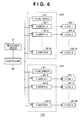
- Fig. 6 is a block diagram showing an example of the configuration of a control system which controls the position and rotation of the movable element by controlling the magnetic field generators;
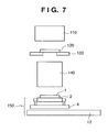
- Fig. 7 is a view showing the schematic arrangement of an exposure apparatus according to the third embodiment of the present invention.
- Figs. 1A and 1B are views schematically showing the arrangement of a single-axis pulse motor (linear pulse motor) according to the first embodiment of the present invention.
- the single-axis pulse motor according to the first embodiment includes a movable element 4 and stator 12.
- the dimension of the movable element 4 in its driving direction is typically smaller than that of the stator 12.
- the movable element 4 contains a magnetic material, and has, on its surface facing the stator 12, a regular array of a plurality of convex portions 21.
- the plurality of convex portions 21 are arrayed with periodicity in at least the driving direction of the movable element 4.
- the stator 12 includes an array of a plurality of magnetic field generators 6, and can be configured as a surface plate.
- Each magnetic field generator 6 includes a yoke 9 and coils 8 which excite the yoke 9.
- the plurality of coils 8 are independently driven by a plurality of driving circuits 13.
- Each yoke 9 contains a magnetic material, and has, on its surface facing the movable element 4, a regular array of a plurality of teeth 10.
- the plurality of teeth 10 are arrayed with periodicity in at least the driving direction of the movable element 4. Excitation of the yoke 9 by the coils 8 forms a magnetic circuit which runs through the teeth 10 of the stator 12 and the convex portions 21 of the movable element 4. With this operation, a thrust acts on the movable element 4 so that it moves relative to the stator 12.
- the movable element 4 can be configured as a stage or a part of it.
- the movable element 4 can mount, for example, a fine moving stage 2 and a driving mechanism 3 which drives the fine moving stage 2.
- the single-axis pulse motor according to this embodiment is mounted in an exposure apparatus, it can be configured as a part of a substrate positioning mechanism which positions a substrate, or an original positioning mechanism which positions an original.
- the fine moving stage 2 can mount a substrate chuck which holds a substrate 1.
- the movable element 4 can be cooled down by a cooling unit 11.
- the driving mechanism 3 which drives the fine moving stage 2, the cooling unit 11, and the like can be supplied with, e.g., power and a refrigerant via flexible interfaces (e.g., a flexible cable and a flexible tube) 7.
- the movable element 4 does not mount an exciting coil to move it, so no heat is generated upon driving the exciting coil.
- the movable element 4 preferably includes a cooling unit 11 in order to remove heat generated due to a magnetic hysteresis loss and an eddy current generated in the movable element 4. Note that the cooling unit 11 is unnecessary if the amount of heat generation falls within a tolerance.
- a measuring device 5 such as a laser interferometer measures the positions of the movable element 4 and fine moving stage 2.
- a controller 14 controls the plurality of driving circuits 13 based on the measurement result obtained by the measuring device 5.
- the controller 14 operates the plurality of driving circuits 13 based on the positioning target position of the movable element 4 and the position of the movable element 4 obtained based on the measurement result obtained by the measuring device 5. At this time, it is also possible to always supply an electric current to the coils 8 of all the magnetic field generators 6.
- coils 8 of a given magnetic field generator 6 above which the movable element 4 is not set are preferably supplied with an electric current immediately before the movable element 4 moves to above the given magnetic field generator 6. If an electric current is supplied to the coils 8 of the given magnetic field generator 6 while the movable element 4 is set above the magnetic field generator 6, it may generate a disturbance to control of the movable element 4. If the amount of heat generation of the coils 8 falls outside a tolerance, a cooling unit for cooling down the coils 8 can be provided.
- Figs. 2A and 2B are views schematically showing the arrangement of a planar pulse motor according to the second embodiment of the present invention.
- the dimension of a movable element 4 in its driving direction is typically smaller than that of a stator 12.
- a measuring device 5 measures the position of the movable element 4 in the X direction (first direction) and Y direction (second direction), and the angular velocity ⁇ Z of rotation of the movable element 4 about the Z-axis.
- the X, Y, and Z directions are orthogonal to each other and based on an X-Y-Z coordinate system.
- a controller 14 corresponding to that in the first embodiment drives the movable element 4 in a two-dimensional plane based on the measurement result obtained by the measuring device 5.
- the stator 12 includes first magnetic field generators 6a each of which is used for driving in the X-axis direction and includes a yoke 9a having teeth 10a, and second magnetic field generators 6b each of which is used for driving in the Y-axis direction and includes a yoke 9b having teeth 10b.
- the first and second magnetic field generators 6a and 6b can have arrangements similar to that of the magnetic field generator 6 according to the first embodiment. Note that the teeth 10a of the first magnetic field generator 6a are arrayed with periodicity in at least the X-axis direction, and the teeth 10b of the second magnetic field generator 6b are arrayed with periodicity in at least the Y-axis direction.
- a plurality of convex portions 21 of the movable element 4 are arrayed with periodicity in at least the X- and Y-axis directions. This is to drive the movable element 4 in the X- and Y-axis directions.
- the first and second magnetic field generators 6a and 6b are preferably arrayed in a checkerboard pattern, as illustrated in Fig. 2A . In other words, it is preferable to arrange one of the first and second magnetic field generators in a portion indicated by a first color, and arrange the other one of them in a portion indicated by a second color.
- Fig. 3 is a view showing an example of the array of the plurality of convex portions 21 of the movable element 4.
- the plurality of convex portions 21 are arrayed in a matrix of a plurality of rows and a plurality of columns.
- a region which isolates the convex portions 21 from each other is filled with a nonmagnetic material 16 so that the movable element 4 has a flat surface facing the stator 12.
- a preferable example of the nonmagnetic material to fill is a resin.
- the movable element 4 includes a nozzle 17 which constitutes an air bearing.
- the movable element 4 is levitated above the guide surface (the surface facing the movable element 4) of the stator 12 by blowing a high-pressure gas from the nozzle 17 to the movable element 4.
- the preferable amount of levitation of the movable element 4 is generally about 5 to 20 ⁇ m.
- the surface of the movable element 4 facing the stator 12, and the surface (guide surface) of the stator 12 facing the movable element 4 preferably have a flatness on the order of, e.g., 1 to 2 ⁇ m.
- Fig. 4 is a view showing another example of the array of the first and second magnetic field generators 6a and 6b.
- the first and second magnetic field generators 6a and 6b are arrayed in a checkerboard pattern.
- the size of each magnetic field generator relative to the movable element 4 in the array example shown in Fig. 4 is smaller than that in the array example shown in Fig. 2A .
- FIG. 6 is a view showing an example of the configuration of a control system which controls the position and rotation of the movable element 4 by controlling the first and second magnetic field generators 6a and 6b.
- a control system 100 exemplified in Fig. 6 includes an X-direction driving circuit 13X and Y-direction driving circuit 13Y corresponding to the driving circuits 13 according to the first embodiment.
- the X-direction driving circuit 13X selectively supplies an electric current to X coils 1 to N (8X-1 to 8X-N) serving as coils 8 of the first magnetic field generators 6a for driving in the X-axis direction.
- the Y-direction driving circuit 13Y selectively supplies an electric current to Y coils 1 to N (8Y-1 to 8Y-N) serving as coils 8 of the second magnetic field generator 6b for driving in the Y-axis direction.
- the X-direction driving circuit 13X includes, for example, an X coil driver 31, and X switches 32-1 to 32-N which serve to supply the electric current from the X coil driver 31 to the X coils 8X-1 to 8X-N in a one-to-one correspondence in accordance with a command from the controller 14.
- the Y-direction driving circuit 13Y includes, for example, a Y coil driver 41, and Y switches 42-1 to 42-N which serve to supply the electric current from the Y coil driver 41 to the Y coils 8Y-1 to 8Y-N in a one-to-one correspondence in accordance with a command from the controller 14.
- Control of the movable element 4 by the control system 100 will be explained in detail next with reference to Fig. 5 .
- a case in which rotation (yawing) of the movable element 4 about the Z-axis is controlled when the planar pulse motor drives the movable element 4 in the X direction will be explained herein as one example.
- rotation of the planar pulse motor about the Z-axis is generally not regulated by, e.g., a guide
- the planar pulse motor requires controlling the angular velocity of the rotation to a target value.
- C indicates the center line which passes through the center of the movable element 4.
- center lines C can be designed to run along the driving direction (e.g., the X and Y direction) of the movable element 4 and pass through the center of gravity of the movable element 4.
- driving direction e.g., the X and Y direction
- coils of magnetic field generators whose regions include both sides of the center line C and which are indicated by label "B" are not energized.
- Coils of magnetic field generators whose regions include portions outside a region facing the movable element 4 and which are indicated by label "D" are not energized, either.
- magnetic field generators to energize are selected from those whose regions do not include the center line C and do not include portions outside a region facing the movable element 4.
- the controller 14 performs control so as to energize coils of magnetic field generators indicated by labels "A" and "C". To achieve this control, the positional relationship between the movable element 4 and each magnetic field generator is calculated in real time based on the measurement result obtained by the measuring device 5. Then, the controller 14 energizes coils of magnetic field generators whose regions do not include the center line of the movable element 4 along its driving direction and do not include portions outside a region facing the movable element 4 and which can drive the movable element 4 in its driving direction.
- magnetic field generators whose regions include the center line of the movable element 4 along its driving direction are energized, this generates a moment in the movable element 4, resulting in complication of arithmetic operation for moment control. Also, if magnetic field generators whose regions include portions outside a region facing the movable element 4 are energized, this generates a moment in the movable element 4. Energization of magnetic field generators whose regions are completely outside a region facing the movable element 4 merely increases power consumption and heat generation, and does not contribute to driving the movable element 4 at all.
- Y indicates the Y-coordinate of the center of the movable element 4
- a , b, c, and d indicate the Y-coordinates of the magnetic field generators indicated by labels "A", "B", “C", and "D”.
- M be the moment to be generated around the center of gravity of the movable element 4.
- Fa be the force, required to generate a moment, of a thrust produced by the magnetic field generators indicated by label "A”.
- Fc be the force, required to generate a moment, of a thrust produced by the magnetic field generators indicated by label "C”.
- the thrust to be produced by the magnetic field generators indicated by label "A” or “C” has a value obtained by adding the driving force of the movable element 4 in the translation direction to the force Fa or Fc.
- L_coil be a half of the dimension, in the Y direction, of the magnetic field generator indicated by label "B”, this magnetic field generator satisfies: Y - b ⁇ L_coil Also, letting L_stator be a half of the dimension of the stator 12 in the Y-axis direction, the magnetic field generator indicated by label “D” satisfies: Y + L_stator - d ⁇ L_coil Thus, the controller 14 selects, as magnetic field generators for moment control, magnetic field generators which satisfy: Y - Y_coil > L_coil Y + L_stator - L_coil > L_coil where Y_coil is the Y-coordinate of each magnetic field generator.
- moment control can be performed using the magnetic field generators for X-direction driving even when the movable element 4 is driven in an oblique direction.
- the Y-coordinate indicated by "Y" is a variable which changes with time upon driving the movable element.
- the magnetic field generators for driving in the X-axis direction are used for moment control of the movable element herein, the same moment direction control of the movable element can be performed even by using the magnetic field generators for driving in the Y-axis direction. It is also possible to use both the magnetic field generators for driving in the X- and Y-axis directions.
- Fig. 7 is a view showing the schematic arrangement of an exposure apparatus according to the third embodiment of the present invention.
- the exposure apparatus according to this embodiment is configured to project the pattern of an original (also called a reticle or a mask) 120 onto a substrate (e.g., a wafer or a glass plate) 1 by a projection optical system 140 to expose the substrate 1.
- the substrate 1 is coated with a photosensitive agent, and the pattern of the original 120 is transferred onto the substrate 1 by this exposure.
- the original 120 is held by an original 120 and illuminated by an illumination optical system 110.
- the substrate 1 is positioned by a positioning mechanism 150.
- the positioning mechanism 150 can be configured according to, for example, the second embodiment. More specifically, the positioning mechanism 150 includes the planar pulse motor according to the second embodiment, and the substrate 1 can be held by a substrate chuck arranged on a movable element 4 of the planar pulse motor.
- a device manufacturing method is suitable for manufacturing, for example, a semiconductor device and a liquid crystal device.
- the method can include a step of transferring the pattern of an original onto a photosensitive agent applied on a substrate using the above-described exposure apparatus, and a step of developing the photosensitive agent.
Landscapes
- Physics & Mathematics (AREA)
- Engineering & Computer Science (AREA)
- General Physics & Mathematics (AREA)
- Chemical & Material Sciences (AREA)
- Combustion & Propulsion (AREA)
- Electromagnetism (AREA)
- Power Engineering (AREA)
- Linear Motors (AREA)
- Exposure And Positioning Against Photoresist Photosensitive Materials (AREA)
- Exposure Of Semiconductors, Excluding Electron Or Ion Beam Exposure (AREA)
- Control Of Linear Motors (AREA)
Abstract
A planar pulse motor includes a movable element and a stator, wherein the movable element contains a magnetic material, and has a plurality of convex portions on a surface thereof facing the stator, the stator includes a plurality of magnetic field generators to drive the movable element, and each magnetic field generator includes a yoke having a plurality of teeth and a coil which excites the yoke, and the planar pulse motor includes a controller which controls rotation of the movable element by energizing magnetic field generators selected from magnetic field generators, whose regions do not include a center line of the movable element along a driving direction of the movable element and do not include portions outside a region facing the movable element, of the plurality of magnetic field generators.
Description
- The present invention relates to a planar pulse motor, an exposure apparatus including the planar pulse motor, and a device manufacturing method using the exposure apparatus.
- A planar pulse motor has the feature that it requires no guide for regulating the position of a movable element in the translation direction. For this reason, a planar pulse motor is advantageous to simplifying, for example, a substrate positioning mechanism in an exposure apparatus which transfers the pattern of an original onto a substrate.
- Japanese Patent Laid-Open No.
6-121520 6-121520 - In general, the exposure apparatus needs to control the substrate along a total of six axial directions: the X, Y, and Z directions and the rotation directions about the X-, Y-, and Z-axes. In the planar pulse motor, as the movable element rotates upon being applied with a moment while the movable element is translated, it may go out of control. Japanese Patent Laid-Open No.
6-121520 - The present invention provides a technique advantageous to rotation control of a movable element in a planar pulse motor.
- The present invention in its first aspect provides a planar pulse motor as specified in
claims 1 to 7. - The present invention in its second aspect provides an exposure apparatus as specified in
claim 8. - The present invention in its third aspect provides a device manufacturing method as specified in
claim 9. - Further features of the present invention will become apparent from the following description of exemplary embodiments with reference to the attached drawings.
-
Fig. 1A is a view schematically showing the arrangement of a single-axis pulse motor (linear pulse motor) according to the first embodiment of the present invention; -
Fig. 1B is a view schematically showing the arrangement of the single-axis pulse motor (linear pulse motor) according to the first embodiment of the present invention; -
Fig. 2A is a view schematically showing the arrangement of a planar pulse motor according to the second embodiment of the present invention; -
Fig. 2B is a view schematically showing the arrangement of the planar pulse motor according to the second embodiment of the present invention; -
Fig. 3 is a view showing an example of the array of a plurality of convex portions on a movable element; -
Fig. 4 is a view showing another example of the array of magnetic field generators; -
Fig. 5 is a view for exemplifying control of the movable element by a control system; -
Fig. 6 is a block diagram showing an example of the configuration of a control system which controls the position and rotation of the movable element by controlling the magnetic field generators; and -
Fig. 7 is a view showing the schematic arrangement of an exposure apparatus according to the third embodiment of the present invention. - Preferred embodiments of the present invention will be described below with reference to the accompanying drawings.
-
Figs. 1A and1B are views schematically showing the arrangement of a single-axis pulse motor (linear pulse motor) according to the first embodiment of the present invention. The single-axis pulse motor according to the first embodiment includes amovable element 4 andstator 12. The dimension of themovable element 4 in its driving direction is typically smaller than that of thestator 12. - The
movable element 4 contains a magnetic material, and has, on its surface facing thestator 12, a regular array of a plurality ofconvex portions 21. The plurality ofconvex portions 21 are arrayed with periodicity in at least the driving direction of themovable element 4. Thestator 12 includes an array of a plurality ofmagnetic field generators 6, and can be configured as a surface plate. Eachmagnetic field generator 6 includes ayoke 9 andcoils 8 which excite theyoke 9. The plurality ofcoils 8 are independently driven by a plurality ofdriving circuits 13. Eachyoke 9 contains a magnetic material, and has, on its surface facing themovable element 4, a regular array of a plurality ofteeth 10. The plurality ofteeth 10 are arrayed with periodicity in at least the driving direction of themovable element 4. Excitation of theyoke 9 by thecoils 8 forms a magnetic circuit which runs through theteeth 10 of thestator 12 and theconvex portions 21 of themovable element 4. With this operation, a thrust acts on themovable element 4 so that it moves relative to thestator 12. - The
movable element 4 can be configured as a stage or a part of it. Themovable element 4 can mount, for example, a fine movingstage 2 and adriving mechanism 3 which drives the fine movingstage 2. If the single-axis pulse motor according to this embodiment is mounted in an exposure apparatus, it can be configured as a part of a substrate positioning mechanism which positions a substrate, or an original positioning mechanism which positions an original. In the substrate positioning mechanism, the fine movingstage 2 can mount a substrate chuck which holds asubstrate 1. Themovable element 4 can be cooled down by acooling unit 11. Thedriving mechanism 3 which drives the fine movingstage 2, thecooling unit 11, and the like can be supplied with, e.g., power and a refrigerant via flexible interfaces (e.g., a flexible cable and a flexible tube) 7. - The
movable element 4 does not mount an exciting coil to move it, so no heat is generated upon driving the exciting coil. However, themovable element 4 preferably includes acooling unit 11 in order to remove heat generated due to a magnetic hysteresis loss and an eddy current generated in themovable element 4. Note that thecooling unit 11 is unnecessary if the amount of heat generation falls within a tolerance. - A
measuring device 5 such as a laser interferometer measures the positions of themovable element 4 and fine movingstage 2. Acontroller 14 controls the plurality ofdriving circuits 13 based on the measurement result obtained by themeasuring device 5. Thecontroller 14 operates the plurality ofdriving circuits 13 based on the positioning target position of themovable element 4 and the position of themovable element 4 obtained based on the measurement result obtained by themeasuring device 5. At this time, it is also possible to always supply an electric current to thecoils 8 of all themagnetic field generators 6. - Nevertheless, to reduce power consumption and suppress heat generation,
coils 8 of a givenmagnetic field generator 6 above which themovable element 4 is not set are preferably supplied with an electric current immediately before themovable element 4 moves to above the givenmagnetic field generator 6. If an electric current is supplied to thecoils 8 of the givenmagnetic field generator 6 while themovable element 4 is set above themagnetic field generator 6, it may generate a disturbance to control of themovable element 4. If the amount of heat generation of thecoils 8 falls outside a tolerance, a cooling unit for cooling down thecoils 8 can be provided. -
Figs. 2A and2B are views schematically showing the arrangement of a planar pulse motor according to the second embodiment of the present invention. In this embodiment as well, the dimension of amovable element 4 in its driving direction is typically smaller than that of astator 12. - In this embodiment, a measuring
device 5 measures the position of themovable element 4 in the X direction (first direction) and Y direction (second direction), and the angular velocity ωZ of rotation of themovable element 4 about the Z-axis. Note that the X, Y, and Z directions are orthogonal to each other and based on an X-Y-Z coordinate system. Acontroller 14 corresponding to that in the first embodiment drives themovable element 4 in a two-dimensional plane based on the measurement result obtained by the measuringdevice 5. - In the planar pulse motor according to this embodiment, the
stator 12 includes firstmagnetic field generators 6a each of which is used for driving in the X-axis direction and includes ayoke 9a having teeth 10a, and secondmagnetic field generators 6b each of which is used for driving in the Y-axis direction and includes ayoke 9b having teeth 10b. The first and secondmagnetic field generators magnetic field generator 6 according to the first embodiment. Note that theteeth 10a of the firstmagnetic field generator 6a are arrayed with periodicity in at least the X-axis direction, and theteeth 10b of the secondmagnetic field generator 6b are arrayed with periodicity in at least the Y-axis direction. - In this embodiment, a plurality of
convex portions 21 of themovable element 4 are arrayed with periodicity in at least the X- and Y-axis directions. This is to drive themovable element 4 in the X- and Y-axis directions. The first and secondmagnetic field generators Fig. 2A . In other words, it is preferable to arrange one of the first and second magnetic field generators in a portion indicated by a first color, and arrange the other one of them in a portion indicated by a second color. -
Fig. 3 is a view showing an example of the array of the plurality ofconvex portions 21 of themovable element 4. The plurality ofconvex portions 21 are arrayed in a matrix of a plurality of rows and a plurality of columns. A region which isolates theconvex portions 21 from each other is filled with anonmagnetic material 16 so that themovable element 4 has a flat surface facing thestator 12. A preferable example of the nonmagnetic material to fill is a resin. - The
movable element 4 includes anozzle 17 which constitutes an air bearing. Themovable element 4 is levitated above the guide surface (the surface facing the movable element 4) of thestator 12 by blowing a high-pressure gas from thenozzle 17 to themovable element 4. The preferable amount of levitation of themovable element 4 is generally about 5 to 20 µm. The surface of themovable element 4 facing thestator 12, and the surface (guide surface) of thestator 12 facing themovable element 4 preferably have a flatness on the order of, e.g., 1 to 2 µm. -
Fig. 4 is a view showing another example of the array of the first and secondmagnetic field generators magnetic field generators movable element 4 in the array example shown inFig. 4 is smaller than that in the array example shown inFig. 2A . -
Fig. 6 is a view showing an example of the configuration of a control system which controls the position and rotation of themovable element 4 by controlling the first and secondmagnetic field generators control system 100 exemplified inFig. 6 includes anX-direction driving circuit 13X and Y-direction driving circuit 13Y corresponding to the drivingcircuits 13 according to the first embodiment. TheX-direction driving circuit 13X selectively supplies an electric current to X coils 1 to N (8X-1 to 8X-N) serving ascoils 8 of the firstmagnetic field generators 6a for driving in the X-axis direction. The Y-direction driving circuit 13Y selectively supplies an electric current to Y coils 1 to N (8Y-1 to 8Y-N) serving ascoils 8 of the secondmagnetic field generator 6b for driving in the Y-axis direction. - The
X-direction driving circuit 13X includes, for example, anX coil driver 31, and X switches 32-1 to 32-N which serve to supply the electric current from theX coil driver 31 to the X coils 8X-1 to 8X-N in a one-to-one correspondence in accordance with a command from thecontroller 14. The Y-direction driving circuit 13Y includes, for example, aY coil driver 41, and Y switches 42-1 to 42-N which serve to supply the electric current from theY coil driver 41 to the Y coils 8Y-1 to 8Y-N in a one-to-one correspondence in accordance with a command from thecontroller 14. - Control of the
movable element 4 by thecontrol system 100 will be explained in detail next with reference toFig. 5 . A case in which rotation (yawing) of themovable element 4 about the Z-axis is controlled when the planar pulse motor drives themovable element 4 in the X direction will be explained herein as one example. Because rotation of the planar pulse motor about the Z-axis is generally not regulated by, e.g., a guide, the planar pulse motor requires controlling the angular velocity of the rotation to a target value. - Referring to
Fig. 5 , C indicates the center line which passes through the center of themovable element 4. Note that center lines C can be designed to run along the driving direction (e.g., the X and Y direction) of themovable element 4 and pass through the center of gravity of themovable element 4. In rotation (yawing) control of themovable element 4 about the Z-axis by thecontroller 14, coils of magnetic field generators whose regions include both sides of the center line C and which are indicated by label "B" are not energized. Coils of magnetic field generators whose regions include portions outside a region facing themovable element 4 and which are indicated by label "D" are not energized, either. In other words, in rotation (yawing) control of themovable element 4 about the Z-axis by thecontroller 14, magnetic field generators to energize are selected from those whose regions do not include the center line C and do not include portions outside a region facing themovable element 4. - Consequently, in driving the
movable element 4 in the X-axis direction, thecontroller 14 performs control so as to energize coils of magnetic field generators indicated by labels "A" and "C". To achieve this control, the positional relationship between themovable element 4 and each magnetic field generator is calculated in real time based on the measurement result obtained by the measuringdevice 5. Then, thecontroller 14 energizes coils of magnetic field generators whose regions do not include the center line of themovable element 4 along its driving direction and do not include portions outside a region facing themovable element 4 and which can drive themovable element 4 in its driving direction. If magnetic field generators whose regions include the center line of themovable element 4 along its driving direction are energized, this generates a moment in themovable element 4, resulting in complication of arithmetic operation for moment control. Also, if magnetic field generators whose regions include portions outside a region facing themovable element 4 are energized, this generates a moment in themovable element 4. Energization of magnetic field generators whose regions are completely outside a region facing themovable element 4 merely increases power consumption and heat generation, and does not contribute to driving themovable element 4 at all. - Referring to
Fig. 5 , Y indicates the Y-coordinate of the center of themovable element 4, and a, b, c, and d indicate the Y-coordinates of the magnetic field generators indicated by labels "A", "B", "C", and "D". Let M be the moment to be generated around the center of gravity of themovable element 4. Let Fa be the force, required to generate a moment, of a thrust produced by the magnetic field generators indicated by label "A". Let Fc be the force, required to generate a moment, of a thrust produced by the magnetic field generators indicated by label "C". Assuming that a clockwise moment is the positive moment, and forces Fa and Fc generated in the X-axis direction are the positive forces, we have:
Moreover, because thrusts to generate a moment need to balance out in total in the translation direction, we have:
Thecontroller 14 can therefore calculate the two forces Fa and Fc based on equations (1) and (2). - The forces Fa and Fc are required only for moment control. Hence, the thrust to be produced by the magnetic field generators indicated by label "A" or "C" has a value obtained by adding the driving force of the
movable element 4 in the translation direction to the force Fa or Fc. - Letting L_coil be a half of the dimension, in the Y direction, of the magnetic field generator indicated by label "B", this magnetic field generator satisfies:

Also, letting L_stator be a half of the dimension of thestator 12 in the Y-axis direction, the magnetic field generator indicated by label "D" satisfies:
Thus, thecontroller 14 selects, as magnetic field generators for moment control, magnetic field generators which satisfy:

where Y_coil is the Y-coordinate of each magnetic field generator. - Although a case in which the
movable element 4 is driven in the X-axis direction has been exemplified above, moment control can be performed using the magnetic field generators for X-direction driving even when themovable element 4 is driven in an oblique direction. In this case, the Y-coordinate indicated by "Y" is a variable which changes with time upon driving the movable element. Also, although the magnetic field generators for driving in the X-axis direction are used for moment control of the movable element herein, the same moment direction control of the movable element can be performed even by using the magnetic field generators for driving in the Y-axis direction. It is also possible to use both the magnetic field generators for driving in the X- and Y-axis directions. -
Fig. 7 is a view showing the schematic arrangement of an exposure apparatus according to the third embodiment of the present invention. The exposure apparatus according to this embodiment is configured to project the pattern of an original (also called a reticle or a mask) 120 onto a substrate (e.g., a wafer or a glass plate) 1 by a projectionoptical system 140 to expose thesubstrate 1. Thesubstrate 1 is coated with a photosensitive agent, and the pattern of the original 120 is transferred onto thesubstrate 1 by this exposure. The original 120 is held by an original 120 and illuminated by an illuminationoptical system 110. Thesubstrate 1 is positioned by apositioning mechanism 150. - The
positioning mechanism 150 can be configured according to, for example, the second embodiment. More specifically, thepositioning mechanism 150 includes the planar pulse motor according to the second embodiment, and thesubstrate 1 can be held by a substrate chuck arranged on amovable element 4 of the planar pulse motor. - A device manufacturing method according to a preferred embodiment of the present invention is suitable for manufacturing, for example, a semiconductor device and a liquid crystal device. The method can include a step of transferring the pattern of an original onto a photosensitive agent applied on a substrate using the above-described exposure apparatus, and a step of developing the photosensitive agent.
- While the present invention has been described with reference to exemplary embodiments, it is to be understood that the invention is not limited to the disclosed exemplary embodiments. The scope of the following claims is to be accorded the broadest interpretation so as to encompass all such modifications and equivalent structures and functions.
Claims (9)
- A planar pulse motor including a movable element and a stator, wherein
the movable element contains a magnetic material, and has a plurality of convex portions on a surface thereof facing the stator,
the stator includes a plurality of magnetic field generators to drive the movable element, and each magnetic field generator includes a yoke having a plurality of teeth and a coil which excites the yoke, and
the planar pulse motor includes a controller which controls rotation of the movable element by energizing magnetic field generators selected from magnetic field generators, whose regions do not include a center line of the movable element along a driving direction of the movable element and do not include portions outside a region facing the movable element, of the plurality of magnetic field generators. - The motor according to claim 1, wherein the controller controls rotation of the movable element by energizing magnetic field generators, whose regions do not include the center line of the movable element along the driving direction of the movable element and do not include the portions outside the region facing the movable element and which can drive the movable element in the driving direction, of the plurality of magnetic field generators.
- The motor according to claim 1 or 2, wherein
the plurality of magnetic field generators include a plurality of first magnetic field generators to drive the movable element in a first direction, and a plurality of second magnetic field generators to drive the movable element in a second direction perpendicular to the first direction, and
the plurality of first magnetic field generators and the plurality of second magnetic field generators are arrayed in a checkerboard pattern. - The motor according to any one of claims 1 to 3, wherein a dimension of the movable element in the driving direction is smaller than a dimension of the stator in the driving direction.
- The motor according to claim 4, wherein, of the coils of the plurality of magnetic field generators, coils to be energized are selected in accordance with a position of the movable element.
- The motor according to claim 3, wherein the movable element includes a center line which runs along the first direction and passes through a center of gravity thereof.
- The motor according to claim 3, wherein the movable element includes center lines which run along the first direction and the second direction and pass through a center of gravity thereof.
- An exposure apparatus which transfers a pattern of an original onto a substrate, the apparatus comprising:a positioning mechanism which positions the substrate; anda projection optical system which projects the pattern of the original onto the substrate,wherein the positioning mechanism includes a planar pulse motor defined in any one of claims 1 to 7, and the substrate is held by a substrate chuck arranged on a movable element of the planar pulse motor.
- A device manufacturing method comprising the steps of:exposing a substrate coated with a photosensitive agent by an exposure apparatus defined in claim 8; anddeveloping the photosensitive agent.
Applications Claiming Priority (1)
| Application Number | Priority Date | Filing Date | Title |
|---|---|---|---|
| JP2008100865A JP2009254173A (en) | 2008-04-08 | 2008-04-08 | Flat type pulse motor, exposure device, and method for manufacturing device |
Publications (1)
| Publication Number | Publication Date |
|---|---|
| EP2109209A2 true EP2109209A2 (en) | 2009-10-14 |
Family
ID=40637912
Family Applications (1)
| Application Number | Title | Priority Date | Filing Date |
|---|---|---|---|
| EP09005119A Withdrawn EP2109209A2 (en) | 2008-04-08 | 2009-04-07 | Planar pulse motor, exposure apparatus, and device manufacturing method |
Country Status (4)
| Country | Link |
|---|---|
| US (1) | US7982344B2 (en) |
| EP (1) | EP2109209A2 (en) |
| JP (1) | JP2009254173A (en) |
| TW (1) | TW200947147A (en) |
Families Citing this family (5)
| Publication number | Priority date | Publication date | Assignee | Title |
|---|---|---|---|---|
| NL2008379A (en) | 2011-03-30 | 2012-10-02 | Asml Netherlands Bv | Planar motor and lithographic apparatus comprising such planar motor. |
| KR101471130B1 (en) * | 2013-07-16 | 2014-12-11 | 숭실대학교산학협력단 | Planar motor and processing apparatus using the same |
| JP7575879B2 (en) * | 2019-03-29 | 2024-10-30 | キヤノン株式会社 | TRANSPORT SYSTEM, MOVABLE ELEMENT, CONTROL DEVICE, AND CONTROL METHOD |
| WO2020203921A1 (en) | 2019-03-29 | 2020-10-08 | キヤノン株式会社 | Transportation system, mover, control device, and control method |
| EP4300794A4 (en) * | 2021-02-25 | 2024-04-24 | Mitsubishi Electric Corporation | Electric motor |
Citations (1)
| Publication number | Priority date | Publication date | Assignee | Title |
|---|---|---|---|---|
| JPH06121520A (en) | 1992-10-02 | 1994-04-28 | Yaskawa Electric Corp | Surface pulse motor |
Family Cites Families (8)
| Publication number | Priority date | Publication date | Assignee | Title |
|---|---|---|---|---|
| US6144119A (en) * | 1999-06-18 | 2000-11-07 | Nikon Corporation | Planar electric motor with dual coil and magnet arrays |
| TW508894B (en) * | 2000-05-20 | 2002-11-01 | Mirae Corpration | Planar motor |
| US6445093B1 (en) * | 2000-06-26 | 2002-09-03 | Nikon Corporation | Planar motor with linear coil arrays |
| DE10211892A1 (en) * | 2001-03-19 | 2002-12-05 | Canon Kk | Linear stepper motor, slide device and exposure device |
| JP2002279141A (en) | 2001-03-19 | 2002-09-27 | Ricoh Co Ltd | Information display system, information display method, information display server and information display program |
| US20030102722A1 (en) * | 2001-12-04 | 2003-06-05 | Toshio Ueta | Moving magnet type planar motor control |
| KR100726711B1 (en) | 2005-12-30 | 2007-06-12 | 한국전기연구원 | Maglev Large Area Stage Device |
| JP2009136065A (en) * | 2007-11-29 | 2009-06-18 | Canon Inc | Planar motor and stage using the same |
-
2008
- 2008-04-08 JP JP2008100865A patent/JP2009254173A/en not_active Withdrawn
-
2009
- 2009-03-25 US US12/410,920 patent/US7982344B2/en not_active Expired - Fee Related
- 2009-04-03 TW TW098111221A patent/TW200947147A/en unknown
- 2009-04-07 EP EP09005119A patent/EP2109209A2/en not_active Withdrawn
Patent Citations (1)
| Publication number | Priority date | Publication date | Assignee | Title |
|---|---|---|---|---|
| JPH06121520A (en) | 1992-10-02 | 1994-04-28 | Yaskawa Electric Corp | Surface pulse motor |
Also Published As
| Publication number | Publication date |
|---|---|
| TW200947147A (en) | 2009-11-16 |
| US20090251012A1 (en) | 2009-10-08 |
| JP2009254173A (en) | 2009-10-29 |
| US7982344B2 (en) | 2011-07-19 |
Similar Documents
| Publication | Publication Date | Title |
|---|---|---|
| US20200225589A1 (en) | Movable body apparatus, pattern forming apparatus and pattern forming method, device manufacturing method, manufacturing method of movable body apparatus, and movable body drive method | |
| US6359677B2 (en) | Stage apparatus, exposure apparatus using the same, and a device manufacturing method | |
| US6525803B2 (en) | Balanced positioning system for use in lithographic apparatus | |
| EP1652003B1 (en) | Wafer table for immersion lithography | |
| EP1788694A1 (en) | Planar motor equipment, stage equipment, exposure equipment and device manufacturing method | |
| EP2998983B1 (en) | Stage apparatus, exposure apparatus and device fabricating method | |
| JP6862543B2 (en) | Motor assembly, lithographic equipment, and device manufacturing methods | |
| KR100369730B1 (en) | Linear motor and stage system, and scanning exposure apparatus and device manufacturing method using the same | |
| JPH11189332A (en) | Stage apparatus, exposure apparatus using the same, and device manufacturing method | |
| US20030057619A1 (en) | Method and apparatus for operating a vibration isolation system having electronic and pneumatic control systems | |
| US20070229794A1 (en) | Stage apparatus, method for controlling the same, exposure apparatus, and method for manufacturing device | |
| US20090316133A1 (en) | Moving body apparatus and exposure apparatus | |
| CN101114129A (en) | Lithography apparatus with planar motor-driven carriage | |
| US7982344B2 (en) | Planar pulse motor, exposure apparatus, and device manufacturing method | |
| US7728462B2 (en) | Monolithic stage devices providing motion in six degrees of freedom | |
| US7333180B2 (en) | Positioning apparatus and exposure apparatus using the same | |
| US20040245861A1 (en) | Linear motor, stage device having this linear motor, exposure device, and device manufacturing method | |
| US7462958B2 (en) | Z actuator with anti-gravity | |
| US20070267995A1 (en) | Six Degree-of-Freedom Stage Apparatus | |
| JP2015073083A (en) | Stage device and driving method thereof | |
| JP2006121069A (en) | Positioning device and lithographic device | |
| JP4122815B2 (en) | Linear motor, stage apparatus, and linear motor control method | |
| JP2008235470A (en) | Planar motor apparatus, stage apparatus, exposure apparatus, and device manufacturing method | |
| JP2002272087A (en) | Armature unit, motor, stage device, exposure apparatus, and device manufacturing method | |
| EP1530090B1 (en) | Lithographic apparatus and device manufacturing method |
Legal Events
| Date | Code | Title | Description |
|---|---|---|---|
| PUAI | Public reference made under article 153(3) epc to a published international application that has entered the european phase |
Free format text: ORIGINAL CODE: 0009012 |
|
| AK | Designated contracting states |
Kind code of ref document: A2 Designated state(s): AT BE BG CH CY CZ DE DK EE ES FI FR GB GR HR HU IE IS IT LI LT LU LV MC MK MT NL NO PL PT RO SE SI SK TR |
|
| STAA | Information on the status of an ep patent application or granted ep patent |
Free format text: STATUS: THE APPLICATION HAS BEEN WITHDRAWN |
|
| 18W | Application withdrawn |
Effective date: 20130830 |