EP2109196A2 - Progressive crimping method - Google Patents
Progressive crimping method Download PDFInfo
- Publication number
- EP2109196A2 EP2109196A2 EP09250830A EP09250830A EP2109196A2 EP 2109196 A2 EP2109196 A2 EP 2109196A2 EP 09250830 A EP09250830 A EP 09250830A EP 09250830 A EP09250830 A EP 09250830A EP 2109196 A2 EP2109196 A2 EP 2109196A2
- Authority
- EP
- European Patent Office
- Prior art keywords
- compression connector
- crimping
- crimp
- crimped
- section
- Prior art date
- Legal status (The legal status is an assumption and is not a legal conclusion. Google has not performed a legal analysis and makes no representation as to the accuracy of the status listed.)
- Granted
Links
Images







Classifications
-
- H—ELECTRICITY
- H01—ELECTRIC ELEMENTS
- H01R—ELECTRICALLY-CONDUCTIVE CONNECTIONS; STRUCTURAL ASSOCIATIONS OF A PLURALITY OF MUTUALLY-INSULATED ELECTRICAL CONNECTING ELEMENTS; COUPLING DEVICES; CURRENT COLLECTORS
- H01R43/00—Apparatus or processes specially adapted for manufacturing, assembling, maintaining, or repairing of line connectors or current collectors or for joining electric conductors
- H01R43/04—Apparatus or processes specially adapted for manufacturing, assembling, maintaining, or repairing of line connectors or current collectors or for joining electric conductors for forming connections by deformation, e.g. crimping tool
- H01R43/048—Crimping apparatus or processes
-
- H—ELECTRICITY
- H01—ELECTRIC ELEMENTS
- H01R—ELECTRICALLY-CONDUCTIVE CONNECTIONS; STRUCTURAL ASSOCIATIONS OF A PLURALITY OF MUTUALLY-INSULATED ELECTRICAL CONNECTING ELEMENTS; COUPLING DEVICES; CURRENT COLLECTORS
- H01R4/00—Electrically-conductive connections between two or more conductive members in direct contact, i.e. touching one another; Means for effecting or maintaining such contact; Electrically-conductive connections having two or more spaced connecting locations for conductors and using contact members penetrating insulation
- H01R4/10—Electrically-conductive connections between two or more conductive members in direct contact, i.e. touching one another; Means for effecting or maintaining such contact; Electrically-conductive connections having two or more spaced connecting locations for conductors and using contact members penetrating insulation effected solely by twisting, wrapping, bending, crimping, or other permanent deformation
- H01R4/18—Electrically-conductive connections between two or more conductive members in direct contact, i.e. touching one another; Means for effecting or maintaining such contact; Electrically-conductive connections having two or more spaced connecting locations for conductors and using contact members penetrating insulation effected solely by twisting, wrapping, bending, crimping, or other permanent deformation by crimping
- H01R4/183—Electrically-conductive connections between two or more conductive members in direct contact, i.e. touching one another; Means for effecting or maintaining such contact; Electrically-conductive connections having two or more spaced connecting locations for conductors and using contact members penetrating insulation effected solely by twisting, wrapping, bending, crimping, or other permanent deformation by crimping for cylindrical elongated bodies, e.g. cables having circular cross-section
- H01R4/186—Electrically-conductive connections between two or more conductive members in direct contact, i.e. touching one another; Means for effecting or maintaining such contact; Electrically-conductive connections having two or more spaced connecting locations for conductors and using contact members penetrating insulation effected solely by twisting, wrapping, bending, crimping, or other permanent deformation by crimping for cylindrical elongated bodies, e.g. cables having circular cross-section using a body comprising a plurality of cable-accommodating recesses or bores
-
- H—ELECTRICITY
- H01—ELECTRIC ELEMENTS
- H01R—ELECTRICALLY-CONDUCTIVE CONNECTIONS; STRUCTURAL ASSOCIATIONS OF A PLURALITY OF MUTUALLY-INSULATED ELECTRICAL CONNECTING ELEMENTS; COUPLING DEVICES; CURRENT COLLECTORS
- H01R9/00—Structural associations of a plurality of mutually-insulated electrical connecting elements, e.g. terminal strips or terminal blocks; Terminals or binding posts mounted upon a base or in a case; Bases therefor
- H01R9/03—Connectors arranged to contact a plurality of the conductors of a multiconductor cable, e.g. tapping connections
-
- Y—GENERAL TAGGING OF NEW TECHNOLOGICAL DEVELOPMENTS; GENERAL TAGGING OF CROSS-SECTIONAL TECHNOLOGIES SPANNING OVER SEVERAL SECTIONS OF THE IPC; TECHNICAL SUBJECTS COVERED BY FORMER USPC CROSS-REFERENCE ART COLLECTIONS [XRACs] AND DIGESTS
- Y10—TECHNICAL SUBJECTS COVERED BY FORMER USPC
- Y10T—TECHNICAL SUBJECTS COVERED BY FORMER US CLASSIFICATION
- Y10T29/00—Metal working
- Y10T29/49—Method of mechanical manufacture
- Y10T29/49002—Electrical device making
- Y10T29/49117—Conductor or circuit manufacturing
- Y10T29/49174—Assembling terminal to elongated conductor
- Y10T29/49181—Assembling terminal to elongated conductor by deforming
-
- Y—GENERAL TAGGING OF NEW TECHNOLOGICAL DEVELOPMENTS; GENERAL TAGGING OF CROSS-SECTIONAL TECHNOLOGIES SPANNING OVER SEVERAL SECTIONS OF THE IPC; TECHNICAL SUBJECTS COVERED BY FORMER USPC CROSS-REFERENCE ART COLLECTIONS [XRACs] AND DIGESTS
- Y10—TECHNICAL SUBJECTS COVERED BY FORMER USPC
- Y10T—TECHNICAL SUBJECTS COVERED BY FORMER US CLASSIFICATION
- Y10T29/00—Metal working
- Y10T29/53—Means to assemble or disassemble
- Y10T29/5313—Means to assemble electrical device
- Y10T29/532—Conductor
- Y10T29/53209—Terminal or connector
- Y10T29/53213—Assembled to wire-type conductor
- Y10T29/53235—Means to fasten by deformation
-
- Y—GENERAL TAGGING OF NEW TECHNOLOGICAL DEVELOPMENTS; GENERAL TAGGING OF CROSS-SECTIONAL TECHNOLOGIES SPANNING OVER SEVERAL SECTIONS OF THE IPC; TECHNICAL SUBJECTS COVERED BY FORMER USPC CROSS-REFERENCE ART COLLECTIONS [XRACs] AND DIGESTS
- Y10—TECHNICAL SUBJECTS COVERED BY FORMER USPC
- Y10T—TECHNICAL SUBJECTS COVERED BY FORMER US CLASSIFICATION
- Y10T29/00—Metal working
- Y10T29/53—Means to assemble or disassemble
- Y10T29/53996—Means to assemble or disassemble by deforming
Definitions
- the present invention relates to compression connectors. More particularly, the present invention relates to systems and methods for progressively crimping compression connectors.
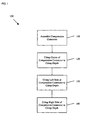
- FIG. 1 is a flow chart of a method 100 for crimping a compression connector 10 according to the prior art.
- the method 100 includes the following steps, which are described in more detail below.
- a compression connector 10 is assembled.
- a first section 12 of the compression connector 10 is crimped to a crimp depth CD.
- a second section 14 of the compression connector 10 is crimped to the crimp depth CD.
- the third section 16 of the compression connector 10 is crimped to the crimp depth CD.
- the prior art crimping method 100 is described with reference to the prior art crimping system 1000 of FIGS. 3-9 .
- the compression connector 10 such as a BURNDY® TYPE YGHP Compression Connector or a BURNDY® YGHP Compression Connector, is prepared or assembled for crimping.
- the compression connector 10 includes the first section 12, the second section 14, and the third section 16, corresponding to the center, the left side, and the right side, respectively, of the compression connector 10.
- the compression connector 10 includes a plurality of electrical conductor receiving channels 18 for receiving one or more electrical conductors 19, such as cables or wires. The wires 19 are inserted into the channels 18.
- assembling the compression connector 10 for crimping is difficult because, prior to crimping, the wires 19 are not retained in the compression connector 10.
- the first section 12 of the compression connector 10 is crimped to the crimp depth CD using a crimping tool (not shown) and a pair of crimping dies 30.
- a crimping tool not shown
- the crimping dies 30 are positioned near the center 12 of the compression connector 10, although precise placement of the crimping dies 30 is difficult and depends on the skill level of the installer.
- the center 12 of the compression connector 10 is crimped or compressed to the crimp depth CD using the crimping tool (see FIG. 4 ).
- the arrows in FIGS. 4-8 indicate movement (e.g., opening and closing) of the crimping tool and the crimping dies 40.
- a crimping tool has a specified tonnage rating (e.g., crimping force applied to contact area between compression connector 10 and crimping dies 30).
- the resultant crimp depth CD depends on the specified tonnage rating of the crimping tool. Additionally, the resultant crimp depth CD also depends on other factors, such as the type of compression connector (e.g., C-Tap, E-Tap, H-Tap) and the type of material (e.g., aluminum, copper, tin plating).
- the second section 14 of the compression connector 10 is crimped to the crimp depth CD.
- the crimping dies 30 are positioned near the left side 14 of the compression connector 10, although precise placement of the crimping dies 30 is difficult and depends on the skill level of the installer.
- the left side 14 of the compression connector 10 is crimped or compressed to the crimp depth CD using the compression tool (see FIG. 4 ).
- the third section 16 of the compression connector 10 is crimped to the crimp depth CD.
- the crimping die 30 is positioned near the right side 16 of the compression connector 20, although precise placement of the crimping dies 30 is difficult and depends on the skill level of the installer.
- the right side 16 of the compression connector 10 is crimped or compressed to the crimp depth CD using the compression tool (see FIG. 4 ).
- the progressive crimping method 100 produces a non-uniform crimp. Moreover, the overall quality of the crimp is highly dependent upon the skill level of the installer.
- U.S. Patent No. 6,227,030 and U.S. Patent No. 6,769,173 disclose prior art crimping methods having shortcomings similar to the prior art crimping method 100.
- a method for progressively crimping a compression connector More particularly, there is a need for a progressive crimping method that is simple, repeatable, and verifiable. Additionally, there is a need for a progressive crimping method that produces a uniform crimp along the entire length of the crimping surface. Furthermore, there is a need for a progressive crimping method that produces a crimp having high mechanical strength, low electrical resistance, and is sealed to prevent the ingress of moisture and other corrosive elements.
- Certain embodiments of the present invention provide a progressive crimping method.
- the method includes assembling a compression connector for crimping, the compression connector including a first section and a second section; crimping the compression connector to a first crimp depth; crimping the first section of the compression connector to a second crimp depth; and crimping the second section of the compression connector to the second crimp depth.
- FIG. 1 is a flow chart of the method 100 for crimping the compression connector 10 according to the prior art.
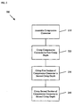
- FIG. 2 is a flow chart of the method 200 for progressively crimping the compression connector 20 according to an embodiment of the present invention.
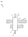
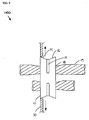
- FIG. 3 illustrates the center 12 of the compression connector 10 positioned in the narrow crimp dies 30 prior to being crimped to the crimp depth CD according to step 120 of the crimping method 100 of FIG. 1 .
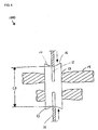
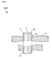
- FIG. 4 illustrates the center 12 of the compression connector 10 being crimped to the crimp depth CD using the narrow crimp dies 30 according to step 120 of the crimping method 100 of FIG. 1 .
- FIG. 5 illustrates the left side 14 of the compression connector 10 positioned in the narrow crimp dies 30 prior to being crimped to the crimp depth CD according to step 130 of the crimping method 100 of FIG. 1 .
- FIG. 6 illustrates the left side 14 of the compression connector 10 being crimped to the crimp depth CD using the narrow crimp dies 30 according to step 130 of the crimping method 100 of FIG. 1 .
- FIG. 7 illustrates the right side 16 of the compression connector 10 positioned in the narrow crimp dies 30 prior to being crimped to the crimp depth CD according to step 140 of the crimping method 100 of FIG. 1 .
- FIG. 8 illustrates the right side 16 of the compression connector 10 being crimped to the crimp depth CD using the narrow crimp dies 30 according to step 140 of the crimping method 100 of FIG. 1 .
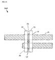
- FIG. 9 illustrates the compression connector 10 after being crimped according to the method 100 of FIG. 1 .
- FIG. 10 illustrates the compression connector 20 assembled for crimping according to step 210 of the progressive crimping method 200 of FIG. 2 .
- FIG. 11 illustrates the compression connector 20 positioned in the side locator crimp dies 40 prior to being crimped to the first crimp depth CD1 according to step 220 of the progressive crimping method 200 of FIG. 2 .
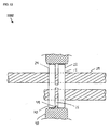
- FIG. 12 illustrates the compression connector 20 positioned in the center locator crimp dies 40 prior to being crimped to the first crimp depth CD1 according to step 220 of the progressive crimping method 200 of FIG. 2 .
- FIG. 13 illustrates the compression connector 20 being crimped to the first crimp depth CD1 using the side locator crimp dies 40 according to step 220 of the progressive crimping method 200 of FIG. 2 .
- FIG. 14 illustrates the compression connector 20 being crimped to the first crimp depth CD 1 using the center locator crimp dies 40 according to step 220 of the progressive crimping method 200 of FIG. 2 .
- FIG. 15 illustrates the first section 22 of the compression connector 20 being crimped to a second crimp depth CD2 using the side locator crimp dies 40 according to step 230 of the progressive crimping method 200 of FIG. 2 .
- FIG. 16 illustrates the first section 22 of the compression connector 20 being crimped to a second crimp depth CD2 using the center locator crimp dies 40 according to step 230 of the progressive crimping method 200 of FIG. 2 .
- FIG. 17 illustrates the second section 24 of the compression connector 20 being crimped to the second crimp depth CD2 using the side locator crimp dies 40 according to step 240 of the progressive crimping method 200 of FIG. 2 .
- FIG. 18 illustrates the second section 24 of the compression connector 20 being crimped to the second crimp depth CD2 using the center locator crimp dies 40 according to step 240 of the progressive crimping method 200 of FIG. 2 .
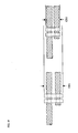
- FIG. 19 illustrates a relative comparison of the first crimp depth CD1 and the second crimp depth CD2.
- FIGS. 20-21 are examples of compression connectors 20 that include one or more identifiers 50 to indicate a type of crimp.
- FIG. 2 is a flow chart of a method 200 for progressively crimping a compression connector 20 according to an embodiment of the present invention.
- the method 200 includes the following steps, which are described in more detail below.
- a compression connector 20 is assembled.
- the compression connector 20 is crimped to a first crimp depth CD1.
- a first section 22 of the compression connector 20 is crimped to a second crimp depth CD2.
- a second section 24 of the compression connector 20 is crimped to the second crimp depth CD2.
- the method 200 is described with reference to the progressive crimping system 2000 of FIGS. 10-21 , but it is understood that other implementations are possible.
- the compression connector 20 such as a PANDUIT® HTCT H-Tap Compression Connector, is prepared or assembled for crimping, as described in U.S. Patent No. 6,818,830 and U.S. Patent No. 7,121,001 , each of which is hereby incorporated by reference in its entirety.
- the compression connector 20 includes the first section 22 and the second section 24.
- the first section 22 and the second section 24 of the compression connector 20 are separated by a plurality of slots 26, and include a plurality of electrical conductor receiving channels 28 (not shown) for receiving one or more electrical conductors 29, such as cables or wires.
- the wires 29 are inserted into the channels 28.
- the wires 29 Prior to crimping, the wires 29 are retained in the compression connector 10 using a cable tie 60.
- the cable tie 60 has been omitted from FIGS. 11-18 .
- the cable tie 60 may be removed from the compression connector 20 after crimping, as shown in FIGS. 19-21 .
- the compression connector 20 is crimped to a first crimp depth CD1 using a crimping tool (not shown), such as a PANDUIT® CT-940CH Crimping Tool or a PANDUIT® CT-2940 Crimping Tool, and a pair of crimping dies 40, such as PANDUIT® CD920-H Crimping Dies or PANDUIT® CD-930H Crimping Dies.
- a crimping tool such as a PANDUIT® CT-940CH Crimping Tool or a PANDUIT® CT-2940 Crimping Tool
- a pair of crimping dies 40 such as PANDUIT® CD920-H Crimping Dies or PANDUIT® CD-930H Crimping Dies.
- the crimping dies 40 include a side locator 42, for example, as described in U.S. Patent No. 7,165,436 , which is hereby incorporated by reference in its entirety. As shown in FIG.
- the side locator 42 of the crimping dies 40 is positioned adjacent to and to the left of the second section 24 of the compression connector 20.
- the crimping dies 40 include a center locator 44.
- the center locator 44 of the crimp dies 40 is positioned in one or more of the slots 26 between the first section 22 and the second section 24 of the compression connector 20.
- 13-18 indicate movement (e.g., opening and closing) of the crimping tool and the crimping dies 40.
- the prior art method 100 and the progressive crimping method 200 are performed using similar compression connectors and similar crimping tools (e.g., crimping tools having similar tonnage ratings)
- the crimp depth CD and the first crimp depth CD1 will be similar, but the second crimp depth CD2 will be less than the crimp depth CD and the first crimp depth CD1, resulting in a tighter overall crimp.
- the first section 22 of the compression connector 20 is crimped to a second crimp depth CD2.
- the side locator 42 of the crimping dies 40 is positioned in one or more of the slots 26 between the first section 22 and the second section 24 of the compression connector 20.
- the center locator 44 of the crimping dies 40 is positioned adjacent to and to the right of the first section 22 of the compression connector 20.
- the first section 22 of the compression connector 20 is crimped or compressed to the second crimp depth CD2 using the crimping tool (see FIG. 19 ).
- the second section 24 of the compression connector 20 is crimped to the second crimp depth CD2.
- the side locator 42 of the crimping dies 40 is positioned adjacent to and to the left of the second section 22 of the compression connector 20.
- the center locator 44 of the crimping dies 40 is positioned in one or more of the slots 26 between the first section 22 and the second section 24 of the compression connector 20.
- the second section 22 of the compression connector 20 is crimped or compressed to the second crimp depth CD2 using the crimping tool (see FIG. 19 ).
- the progressive crimping method 200 may be preformed using C-Tap, E-Tap, or H-Tap compression connectors.
- the crimp dies 40 include the side locator 42 or the center locator 44, the overall quality of crimp is not as dependent on the skill level of the installer.
- the crimp is tighter than the crimp achieved using the prior art progressive crimping method 100.
- a relative comparison of the first crimp depth CD1 and the second crimp depth CD2 is provided in FIG. 19 .
- the compression connector 20 includes an identifier 50, such as "PG25", to indicate a type of crimp.
- the second section 24 of the compression connector 20 includes the identifier 50, indicating that the compression connector 20 has been crimped to the first crimp depth CD1.
- the first section 22 and the second section 24 of the compression connector 20 include the identifier 50, indicating that the compression connector 20 has been crimped to the second crimp depth CD2.
- the identifier 50 is embossed on the compression connector 20 using the crimping tool and the crimping dies 40. Other forms of identification, such as labeling or color-coding, are likewise contemplated.
- Certain embodiments of the present invention provide a progressive crimping method 200 that is simple, repeatable, and verifiable.
- Certain embodiments of the present invention provide a progressive crimping method 200 that produces a uniform crimp along the entire length of the crimping surface.
- Certain embodiments of the present invention provide a progressive crimping method 200 that produces a crimp having high mechanical strength, low electrical resistance, and is sealed to prevent the ingress of moisture and other corrosive elements.
- a compression connector 20 crimped to the first crimp depth CD1 is capable of meeting the requirements of UL 467 for direct burial grounding connectors.
- a compression connector 20 crimped to the second crimp depth CD2 is also capable of meeting the more stringent requirements of IEEE Standard 837-2002, which were developed to qualify permanent connections used in electrical substation grounding.
Landscapes
- Engineering & Computer Science (AREA)
- Manufacturing & Machinery (AREA)
- Manufacturing Of Electrical Connectors (AREA)
- Connections Effected By Soldering, Adhesion, Or Permanent Deformation (AREA)
Abstract
Description
- The present invention relates to compression connectors. More particularly, the present invention relates to systems and methods for progressively crimping compression connectors.
-
FIG. 1 is a flow chart of amethod 100 for crimping acompression connector 10 according to the prior art. Themethod 100 includes the following steps, which are described in more detail below. Atstep 110, acompression connector 10 is assembled. Atstep 120, afirst section 12 of thecompression connector 10 is crimped to a crimp depth CD. Atstep 130, asecond section 14 of thecompression connector 10 is crimped to the crimp depth CD. Atstep 140, thethird section 16 of thecompression connector 10 is crimped to the crimp depth CD. The priorart crimping method 100 is described with reference to the priorart crimping system 1000 ofFIGS. 3-9 . - At
step 110, thecompression connector 10, such as a BURNDY® TYPE YGHP Compression Connector or a BURNDY® YGHP Compression Connector, is prepared or assembled for crimping. For example, as best seen inFIG. 3 , thecompression connector 10 includes thefirst section 12, thesecond section 14, and thethird section 16, corresponding to the center, the left side, and the right side, respectively, of thecompression connector 10. Thecompression connector 10 includes a plurality of electricalconductor receiving channels 18 for receiving one or moreelectrical conductors 19, such as cables or wires. Thewires 19 are inserted into thechannels 18. However, assembling thecompression connector 10 for crimping is difficult because, prior to crimping, thewires 19 are not retained in thecompression connector 10. - At
step 120, thefirst section 12 of thecompression connector 10 is crimped to the crimp depth CD using a crimping tool (not shown) and a pair of crimping dies 30. For example, as best seen inFIG. 3 , thecrimping dies 30 are positioned near thecenter 12 of thecompression connector 10, although precise placement of thecrimping dies 30 is difficult and depends on the skill level of the installer. Next, as best seen inFIG. 4 , thecenter 12 of thecompression connector 10 is crimped or compressed to the crimp depth CD using the crimping tool (seeFIG. 4 ). The arrows inFIGS. 4-8 indicate movement (e.g., opening and closing) of the crimping tool and the crimping dies 40. Typically, a crimping tool has a specified tonnage rating (e.g., crimping force applied to contact area betweencompression connector 10 and crimping dies 30). The resultant crimp depth CD depends on the specified tonnage rating of the crimping tool. Additionally, the resultant crimp depth CD also depends on other factors, such as the type of compression connector (e.g., C-Tap, E-Tap, H-Tap) and the type of material (e.g., aluminum, copper, tin plating). - At
step 130, thesecond section 14 of thecompression connector 10 is crimped to the crimp depth CD. For example, as best seen inFIG. 5 , thecrimping dies 30 are positioned near theleft side 14 of thecompression connector 10, although precise placement of thecrimping dies 30 is difficult and depends on the skill level of the installer. Next, as best seen inFIG. 6 , theleft side 14 of thecompression connector 10 is crimped or compressed to the crimp depth CD using the compression tool (seeFIG. 4 ). - At
step 140, thethird section 16 of thecompression connector 10 is crimped to the crimp depth CD. For example, as best seen inFIG. 7 , thecrimping die 30 is positioned near theright side 16 of thecompression connector 20, although precise placement of thecrimping dies 30 is difficult and depends on the skill level of the installer. Next, as best seen inFIG. 8 , theright side 16 of thecompression connector 10 is crimped or compressed to the crimp depth CD using the compression tool (seeFIG. 4 ). - As best seen in
FIG. 9 , theprogressive crimping method 100 produces a non-uniform crimp. Moreover, the overall quality of the crimp is highly dependent upon the skill level of the installer. -
U.S. Patent No. 6,227,030 andU.S. Patent No. 6,769,173 disclose prior art crimping methods having shortcomings similar to the priorart crimping method 100. - Therefore, there is a need for a method for progressively crimping a compression connector. More particularly, there is a need for a progressive crimping method that is simple, repeatable, and verifiable. Additionally, there is a need for a progressive crimping method that produces a uniform crimp along the entire length of the crimping surface. Furthermore, there is a need for a progressive crimping method that produces a crimp having high mechanical strength, low electrical resistance, and is sealed to prevent the ingress of moisture and other corrosive elements.
- Certain embodiments of the present invention provide a progressive crimping method. The method includes assembling a compression connector for crimping, the compression connector including a first section and a second section; crimping the compression connector to a first crimp depth; crimping the first section of the compression connector to a second crimp depth; and crimping the second section of the compression connector to the second crimp depth.
-
FIG. 1 is a flow chart of themethod 100 for crimping thecompression connector 10 according to the prior art. -
FIG. 2 is a flow chart of themethod 200 for progressively crimping thecompression connector 20 according to an embodiment of the present invention. -
FIG. 3 illustrates thecenter 12 of thecompression connector 10 positioned in the narrow crimp dies 30 prior to being crimped to the crimp depth CD according tostep 120 of thecrimping method 100 ofFIG. 1 . -
FIG. 4 illustrates thecenter 12 of thecompression connector 10 being crimped to the crimp depth CD using the narrow crimp dies 30 according tostep 120 of thecrimping method 100 ofFIG. 1 . -
FIG. 5 illustrates theleft side 14 of thecompression connector 10 positioned in the narrow crimp dies 30 prior to being crimped to the crimp depth CD according tostep 130 of thecrimping method 100 ofFIG. 1 . -
FIG. 6 illustrates theleft side 14 of thecompression connector 10 being crimped to the crimp depth CD using the narrow crimp dies 30 according tostep 130 of thecrimping method 100 ofFIG. 1 . -
FIG. 7 illustrates theright side 16 of thecompression connector 10 positioned in the narrow crimp dies 30 prior to being crimped to the crimp depth CD according tostep 140 of thecrimping method 100 ofFIG. 1 . -
FIG. 8 illustrates theright side 16 of thecompression connector 10 being crimped to the crimp depth CD using the narrow crimp dies 30 according tostep 140 of thecrimping method 100 ofFIG. 1 . -
FIG. 9 illustrates thecompression connector 10 after being crimped according to themethod 100 ofFIG. 1 . -
FIG. 10 illustrates thecompression connector 20 assembled for crimping according tostep 210 of theprogressive crimping method 200 ofFIG. 2 . -
FIG. 11 illustrates thecompression connector 20 positioned in the side locator crimp dies 40 prior to being crimped to the first crimp depth CD1 according tostep 220 of theprogressive crimping method 200 ofFIG. 2 . -
FIG. 12 illustrates thecompression connector 20 positioned in the center locator crimp dies 40 prior to being crimped to the first crimp depth CD1 according tostep 220 of theprogressive crimping method 200 ofFIG. 2 . -
FIG. 13 illustrates thecompression connector 20 being crimped to the first crimp depth CD1 using the side locator crimp dies 40 according tostep 220 of theprogressive crimping method 200 ofFIG. 2 . -
FIG. 14 illustrates thecompression connector 20 being crimped to the first crimp depth CD 1 using the center locator crimp dies 40 according tostep 220 of theprogressive crimping method 200 ofFIG. 2 . -
FIG. 15 illustrates thefirst section 22 of thecompression connector 20 being crimped to a second crimp depth CD2 using the side locator crimp dies 40 according tostep 230 of theprogressive crimping method 200 ofFIG. 2 . -
FIG. 16 illustrates thefirst section 22 of thecompression connector 20 being crimped to a second crimp depth CD2 using the center locator crimp dies 40 according tostep 230 of theprogressive crimping method 200 ofFIG. 2 . -
FIG. 17 illustrates thesecond section 24 of thecompression connector 20 being crimped to the second crimp depth CD2 using the side locator crimp dies 40 according tostep 240 of theprogressive crimping method 200 ofFIG. 2 . -
FIG. 18 illustrates thesecond section 24 of thecompression connector 20 being crimped to the second crimp depth CD2 using the center locator crimp dies 40 according tostep 240 of theprogressive crimping method 200 ofFIG. 2 . -
FIG. 19 illustrates a relative comparison of the first crimp depth CD1 and the second crimp depth CD2. -
FIGS. 20-21 are examples ofcompression connectors 20 that include one ormore identifiers 50 to indicate a type of crimp. - The foregoing summary, as well as the following detailed description of certain embodiments of the present invention, will be better understood when read in conjunction with the appended drawings. For the purpose of illustrating the invention, certain embodiments are shown in the drawings. It should be understood, however, that the present invention is not limited to the arrangements and instrumentality shown in the attached drawings.
-
FIG. 2 is a flow chart of amethod 200 for progressively crimping acompression connector 20 according to an embodiment of the present invention. Themethod 200 includes the following steps, which are described in more detail below. Atstep 210, acompression connector 20 is assembled. Atstep 220, thecompression connector 20 is crimped to a first crimp depth CD1. Atstep 230, afirst section 22 of thecompression connector 20 is crimped to a second crimp depth CD2. Atstep 240, asecond section 24 of thecompression connector 20 is crimped to the second crimp depth CD2. Themethod 200 is described with reference to the progressive crimpingsystem 2000 ofFIGS. 10-21 , but it is understood that other implementations are possible. - At
step 210, thecompression connector 20, such as a PANDUIT® HTCT H-Tap Compression Connector, is prepared or assembled for crimping, as described inU.S. Patent No. 6,818,830 andU.S. Patent No. 7,121,001 , each of which is hereby incorporated by reference in its entirety. For example, as best seen inFIG. 10 , thecompression connector 20 includes thefirst section 22 and thesecond section 24. Thefirst section 22 and thesecond section 24 of thecompression connector 20 are separated by a plurality ofslots 26, and include a plurality of electrical conductor receiving channels 28 (not shown) for receiving one or moreelectrical conductors 29, such as cables or wires. Thewires 29 are inserted into thechannels 28. Prior to crimping, thewires 29 are retained in thecompression connector 10 using acable tie 60. For clarity, thecable tie 60 has been omitted fromFIGS. 11-18 . Thecable tie 60 may be removed from thecompression connector 20 after crimping, as shown inFIGS. 19-21 . - At
step 220, thecompression connector 20 is crimped to a first crimp depth CD1 using a crimping tool (not shown), such as a PANDUIT® CT-940CH Crimping Tool or a PANDUIT® CT-2940 Crimping Tool, and a pair of crimping dies 40, such as PANDUIT® CD920-H Crimping Dies or PANDUIT® CD-930H Crimping Dies. For example, as best seen inFIG. 11 , the crimping dies 40 include aside locator 42, for example, as described inU.S. Patent No. 7,165,436 , which is hereby incorporated by reference in its entirety. As shown inFIG. 11 , theside locator 42 of the crimping dies 40 is positioned adjacent to and to the left of thesecond section 24 of thecompression connector 20. Alternatively, as best seen inFIG. 12 , the crimping dies 40 include acenter locator 44. As shown inFIG. 12 , thecenter locator 44 of the crimp dies 40 is positioned in one or more of theslots 26 between thefirst section 22 and thesecond section 24 of thecompression connector 20. Next, as best seen inFIG. 13 andFIG. 14 , thefirst section 22 and thesecond section 24 of thecompression connector 20 are crimped or compressed to the first crimp depth CD1 using the crimping tool (seeFIG. 19 ). The arrows inFIGS. 13-18 indicate movement (e.g., opening and closing) of the crimping tool and the crimping dies 40. If, for example, theprior art method 100 and the progressive crimpingmethod 200 are performed using similar compression connectors and similar crimping tools (e.g., crimping tools having similar tonnage ratings), then the crimp depth CD and the first crimp depth CD1 will be similar, but the second crimp depth CD2 will be less than the crimp depth CD and the first crimp depth CD1, resulting in a tighter overall crimp. - At
step 230, thefirst section 22 of thecompression connector 20 is crimped to a second crimp depth CD2. For example, as best seen inFIG. 15 , theside locator 42 of the crimping dies 40 is positioned in one or more of theslots 26 between thefirst section 22 and thesecond section 24 of thecompression connector 20. Alternatively, as best seen inFIG. 16 , thecenter locator 44 of the crimping dies 40 is positioned adjacent to and to the right of thefirst section 22 of thecompression connector 20. Next, thefirst section 22 of thecompression connector 20 is crimped or compressed to the second crimp depth CD2 using the crimping tool (seeFIG. 19 ). - At
step 240, thesecond section 24 of thecompression connector 20 is crimped to the second crimp depth CD2. For example, as best seen inFIG. 17 , theside locator 42 of the crimping dies 40 is positioned adjacent to and to the left of thesecond section 22 of thecompression connector 20. Alternatively, as best seen inFIG. 18 , thecenter locator 44 of the crimping dies 40 is positioned in one or more of theslots 26 between thefirst section 22 and thesecond section 24 of thecompression connector 20. Next, thesecond section 22 of thecompression connector 20 is crimped or compressed to the second crimp depth CD2 using the crimping tool (seeFIG. 19 ). - In certain embodiments of the present invention, the progressive crimping
method 200 may be preformed using C-Tap, E-Tap, or H-Tap compression connectors. - Because the crimp dies 40 include the
side locator 42 or thecenter locator 44, the overall quality of crimp is not as dependent on the skill level of the installer. - Because the
first section 22 and thesecond section 24 of thecompression connector 20 are crimped together, and then separately, the crimp is tighter than the crimp achieved using the prior art progressive crimpingmethod 100. - A relative comparison of the first crimp depth CD1 and the second crimp depth CD2 is provided in
FIG. 19 . - In certain embodiments of the present invention, the
compression connector 20 includes anidentifier 50, such as "PG25", to indicate a type of crimp. For example, as best seen inFIG. 20 , thesecond section 24 of thecompression connector 20 includes theidentifier 50, indicating that thecompression connector 20 has been crimped to the first crimp depth CD1. Alternatively, as best seen inFIG. 21 , thefirst section 22 and thesecond section 24 of thecompression connector 20 include theidentifier 50, indicating that thecompression connector 20 has been crimped to the second crimp depth CD2. In the above examples, theidentifier 50 is embossed on thecompression connector 20 using the crimping tool and the crimping dies 40. Other forms of identification, such as labeling or color-coding, are likewise contemplated. - Certain embodiments of the present invention provide a progressive crimping
method 200 that is simple, repeatable, and verifiable. - Certain embodiments of the present invention provide a progressive crimping
method 200 that produces a uniform crimp along the entire length of the crimping surface. - Certain embodiments of the present invention provide a progressive crimping
method 200 that produces a crimp having high mechanical strength, low electrical resistance, and is sealed to prevent the ingress of moisture and other corrosive elements. For example, acompression connector 20 crimped to the first crimp depth CD1 is capable of meeting the requirements of UL 467 for direct burial grounding connectors. As another example, acompression connector 20 crimped to the second crimp depth CD2 is also capable of meeting the more stringent requirements of IEEE Standard 837-2002, which were developed to qualify permanent connections used in electrical substation grounding. - While particular elements, embodiments and applications of the present invention have been shown and described, it is understood that the invention is not limited thereto since modifications may be made by those skilled in the art, particularly in light of the foregoing teaching. It is therefore contemplated by the appended claims to cover such modifications and incorporate those features that come within the spirit and scope of the invention.
Claims (15)
- A method for progressively crimping a compression connector, the method comprising:assembling a compression connector for crimping, the compression connector including a first section and a second section;crimping the compression connector to a first crimp depth;crimping the first section of the compression connector to a second crimp depth; andcrimping the second section of the compression connector to the second crimp depth.
- The method of claim 1, wherein the compression connector includes on of an C-tap compression connector, an E-tap compression connector, or an H-tap compression connector.
- The method of claim 1, wherein the first and second sections of the compression connector are separated by one or more slots.
- The method of claim 1, wherein the compression connector is crimped using a pair of crimping dies.
- The method of claim 4, wherein the crimping dies include one or more locators.
- The method of claim 5, wherein the one or more locators include one or more side locators.
- The method of claim 5, wherein the one or more locators include one or more center locators.
- The method of claim 1, wherein the compression connector includes one or more identifiers to indicate a type of crimp.
- The method of claim 8, wherein the one or more identifiers are applied to the compression connector using a pair of crimping dies.
- The method of claim 1, further including applying a first identifier to the compression connector when the compression connector is crimped to the first crimp depth, wherein the first identifier indicates that the compression connector has been crimped to the first crimp depth.
- The method of claim 10, further including applying a second identifier to the compression connector when the compression connector is progressively crimped to the second crimp depth, wherein the second identifier indicates that the compression connector has been crimped to the second crimp depth.
- A crimping tool adapted to apply one or more identifiers to a compression connector when the compression connector is crimped, wherein the one or more identifiers indicate a type of crimp.
- A pair of crimping dies adapted to apply one or more identifiers to a compression connector when the compression connector is crimped, wherein the one or more identifiers indicate a type of crimp.
- The crimping tool of claim 12 or crimping dies of claim 13, wherein the crimping tool or dies are adapted to apply a first identifier to a compression connector when the compression connector is crimped to a first crimp depth.
- The crimping tool or dies of claim 14, wherein the crimping tool or dies are adapted to apply a second identifier to the compression connector when the compression connector is progressively crimped to a second crimp depth.
Applications Claiming Priority (1)
| Application Number | Priority Date | Filing Date | Title |
|---|---|---|---|
| US12/099,927 US8869584B2 (en) | 2008-04-09 | 2008-04-09 | Progressive crimping method |
Publications (3)
| Publication Number | Publication Date |
|---|---|
| EP2109196A2 true EP2109196A2 (en) | 2009-10-14 |
| EP2109196A3 EP2109196A3 (en) | 2014-05-07 |
| EP2109196B1 EP2109196B1 (en) | 2018-12-19 |
Family
ID=40680677
Family Applications (1)
| Application Number | Title | Priority Date | Filing Date |
|---|---|---|---|
| EP09250830.8A Not-in-force EP2109196B1 (en) | 2008-04-09 | 2009-03-24 | Progressive crimping method |
Country Status (4)
| Country | Link |
|---|---|
| US (1) | US8869584B2 (en) |
| EP (1) | EP2109196B1 (en) |
| CN (1) | CN101554720B (en) |
| MX (1) | MX2009003814A (en) |
Cited By (1)
| Publication number | Priority date | Publication date | Assignee | Title |
|---|---|---|---|---|
| US9673537B2 (en) | 2013-03-15 | 2017-06-06 | Thomas & Betts International, Llc | Wire compression connector |
Families Citing this family (14)
| Publication number | Priority date | Publication date | Assignee | Title |
|---|---|---|---|---|
| US8572838B2 (en) | 2011-03-02 | 2013-11-05 | Honeywell International Inc. | Methods for fabricating high temperature electromagnetic coil assemblies |
| US8466767B2 (en) | 2011-07-20 | 2013-06-18 | Honeywell International Inc. | Electromagnetic coil assemblies having tapered crimp joints and methods for the production thereof |
| US8860541B2 (en) | 2011-10-18 | 2014-10-14 | Honeywell International Inc. | Electromagnetic coil assemblies having braided lead wires and methods for the manufacture thereof |
| US9076581B2 (en) | 2012-04-30 | 2015-07-07 | Honeywell International Inc. | Method for manufacturing high temperature electromagnetic coil assemblies including brazed braided lead wires |
| US8754735B2 (en) | 2012-04-30 | 2014-06-17 | Honeywell International Inc. | High temperature electromagnetic coil assemblies including braided lead wires and methods for the fabrication thereof |
| US9027228B2 (en) | 2012-11-29 | 2015-05-12 | Honeywell International Inc. | Method for manufacturing electromagnetic coil assemblies |
| US9722464B2 (en) | 2013-03-13 | 2017-08-01 | Honeywell International Inc. | Gas turbine engine actuation systems including high temperature actuators and methods for the manufacture thereof |
| WO2016033490A1 (en) | 2014-08-29 | 2016-03-03 | Hubbell Incorporated | Nest dies, indent crimp die sets, and crimp tools having such die sets |
| US10243313B2 (en) | 2015-07-07 | 2019-03-26 | Thomas & Betts International Llc | Cable compression die assembly for crimp connections |
| CN105977679B (en) * | 2016-05-20 | 2019-02-15 | 中航光电科技股份有限公司 | An electrical connector contact piece and a preparation tool for the electrical connector contact piece |
| US11394165B2 (en) | 2017-06-29 | 2022-07-19 | Hubbell Incorporated | Repositionable tool die |
| US10693246B2 (en) | 2018-08-21 | 2020-06-23 | Lear Corporation | Terminal assembly for use with conductors of different sizes and method of assembling |
| US10574015B1 (en) | 2018-08-21 | 2020-02-25 | Lear Corporation | Terminal assembly and method |
| US10581181B1 (en) | 2018-08-21 | 2020-03-03 | Lear Corporation | Terminal assembly and method |
Citations (4)
| Publication number | Priority date | Publication date | Assignee | Title |
|---|---|---|---|---|
| US6227030B1 (en) | 1999-12-17 | 2001-05-08 | Fci Usa, Inc. | Electrical connector crimping die with over-crimp prevention surface and method |
| US6769173B2 (en) | 2001-08-29 | 2004-08-03 | Fci Americas Technology, Inc. | Electrical connector crimping die |
| US6818830B2 (en) | 2002-09-26 | 2004-11-16 | Panduit Corp. | H-tap compression connector |
| US7165436B2 (en) | 2003-12-15 | 2007-01-23 | Panduit Corp. | Crimp die locator |
Family Cites Families (45)
| Publication number | Priority date | Publication date | Assignee | Title |
|---|---|---|---|---|
| US2566725A (en) | 1948-02-04 | 1951-09-04 | Chance Co Ab | U-bolt connector |
| US2758491A (en) * | 1951-12-06 | 1956-08-14 | Aircraft Marine Prod Inc | Crimping dies for electrical connectors |
| US3085313A (en) | 1953-04-09 | 1963-04-16 | Amp Inc | Method of making an electrical connection |
| US3101766A (en) * | 1955-04-14 | 1963-08-27 | Amp Inc | Crimping apparatus |
| US2953185A (en) | 1957-09-13 | 1960-09-20 | Burndy Corp | Terminal and cable stop |
| US3032603A (en) | 1961-02-27 | 1962-05-01 | Effco Inc | Connector with temporary cable holding means |
| US3146519A (en) * | 1961-03-21 | 1964-09-01 | Etc Inc | Method of making electrical connections |
| US3267717A (en) | 1964-01-10 | 1966-08-23 | Burndy Corp | Open-side compression tool |
| US3235654A (en) * | 1964-03-19 | 1966-02-15 | Thomas & Betts Corp | Compression tap |
| US3275738A (en) * | 1964-04-30 | 1966-09-27 | Anderson Electric Corp | Cable connector with crimping die locating grooves |
| US3345692A (en) * | 1965-09-22 | 1967-10-10 | Amp Inc | Dies for applying insulation to an electrical connector |
| US3457764A (en) | 1967-12-04 | 1969-07-29 | United Carr Inc | Wire crimping tool |
| US3504417A (en) | 1968-02-29 | 1970-04-07 | Sargent & Co | Locator in a crimping tool for an electrical connector |
| US3525107A (en) | 1968-05-08 | 1970-08-25 | Amp Inc | Terminal crimping,wirecutting and insulation stripping tool |
| US3665927A (en) | 1968-05-29 | 1972-05-30 | Sutures Inc | Impregnation of polyfilamentous sutures with synthetic polymer particles |
| AU430525B2 (en) | 1969-08-11 | 1972-11-29 | Kearney-National Inc | Self-energized tool for crimping connection fitting about electrical conductor lines |
| US3746777A (en) | 1972-08-30 | 1973-07-17 | Anderson Electric Corp | Compression connector for electrical conductors with tabs in series |
| US3889048A (en) | 1972-10-04 | 1975-06-10 | Erico Prod Inc | Electrical connector and clip therefor having barbs to ensure proper preassembly |
| US4019236A (en) | 1975-12-31 | 1977-04-26 | Amp Incorporated | Crimping press clamp for electrical connectors |
| US4126936A (en) * | 1977-09-29 | 1978-11-28 | Koller Joseph A | Identification system for point to point wiring |
| US4350843A (en) | 1978-08-31 | 1982-09-21 | Square D Company | Method and system for crimping a metal connector |
| US4292833A (en) | 1979-06-22 | 1981-10-06 | Lapp Ellsworth W | Crimping tool |
| US4385515A (en) * | 1981-11-09 | 1983-05-31 | Raychem Corporation | Calibrated cable connector crimping tool and method of use |
| US4974314A (en) | 1989-09-29 | 1990-12-04 | Thomas & Betts Corporation | Crimping tool having spring loaded contact locator |
| US5042285A (en) | 1990-05-21 | 1991-08-27 | Thomas & Betts Corporation | Crimping tool having improved crimping dies |
| US5193379A (en) | 1990-09-27 | 1993-03-16 | Burndy Corporation | Dieless compression head |
| PH30310A (en) | 1991-02-15 | 1997-03-06 | Burndy Corp | Full closure h-shaped connector |
| US5396033A (en) | 1992-12-09 | 1995-03-07 | Thomas & Betts Corporation | H-tap compression connector |
| US5421186A (en) | 1993-04-15 | 1995-06-06 | Burndy Corporation | Crimp die with positive connector stop |
| US5428983A (en) | 1994-01-24 | 1995-07-04 | Liu; Lien-Huang | Terminal pliers |
| US5657417A (en) | 1995-05-02 | 1997-08-12 | Burndy Corporation | Control for battery powered tool |
| US6452103B1 (en) | 1997-08-19 | 2002-09-17 | Thomas & Betts International, Inc. | Compression connector |
| US5924322A (en) | 1997-10-16 | 1999-07-20 | Panduit Corp. | Multiple position locator for crimping tools |
| US6101862A (en) | 1998-05-20 | 2000-08-15 | Framatome Connectors Usa, Inc. | Hydraulic compression tool |
| DE10127854B4 (en) | 2000-06-12 | 2006-02-02 | Yazaki Corp. | Method for checking the crimping state of a crimping terminal and crimping terminal therefor |
| US6552271B2 (en) | 2001-07-10 | 2003-04-22 | Fci Usa, Inc. | Electrical compression connector |
| US6538204B2 (en) | 2001-07-10 | 2003-03-25 | Fci Usa, Inc. | Electrical compression connector |
| US6446482B1 (en) | 2001-09-17 | 2002-09-10 | Fci Americas Technology, Inc. | Battery operated hydraulic compression tool with rapid ram advance |
| DE20217733U1 (en) | 2002-11-16 | 2004-04-01 | Weidmüller Interface Gmbh & Co. | Crimping Tool |
| JP4130931B2 (en) * | 2004-01-28 | 2008-08-13 | 木本 三保子 | Cylindrical sleeve compression method and compressor for stranded wire |
| US20070134980A1 (en) | 2004-08-18 | 2007-06-14 | Trans-Matic Manufacturing Co., Inc. | Crimp sleeve connector having crimp indicator |
| FR2887069B1 (en) | 2005-06-14 | 2016-09-09 | Airbus France | ELECTRICAL CABLE WITH EXTERNAL MARKING AND METHOD OF CRIMPING A TEST OF A CONTACT ON AN ELECTRICAL CABLE WITH EXTERNAL MARKING |
| US7493791B2 (en) | 2006-07-27 | 2009-02-24 | Fci Americas Technology, Inc. | Electrical connector crimp die with crimp overlap indicia forming |
| JP2009272141A (en) | 2008-05-07 | 2009-11-19 | Autonetworks Technologies Ltd | Crimping terminal, and method for manufacturing of electric cable with terminal |
| US8839653B2 (en) | 2008-06-02 | 2014-09-23 | Hubbell Incorporated | Crimping tool connector locator |
-
2008
- 2008-04-09 US US12/099,927 patent/US8869584B2/en active Active
-
2009
- 2009-03-24 EP EP09250830.8A patent/EP2109196B1/en not_active Not-in-force
- 2009-04-08 CN CN200910133147.7A patent/CN101554720B/en not_active Expired - Fee Related
- 2009-04-08 MX MX2009003814A patent/MX2009003814A/en active IP Right Grant
Patent Citations (5)
| Publication number | Priority date | Publication date | Assignee | Title |
|---|---|---|---|---|
| US6227030B1 (en) | 1999-12-17 | 2001-05-08 | Fci Usa, Inc. | Electrical connector crimping die with over-crimp prevention surface and method |
| US6769173B2 (en) | 2001-08-29 | 2004-08-03 | Fci Americas Technology, Inc. | Electrical connector crimping die |
| US6818830B2 (en) | 2002-09-26 | 2004-11-16 | Panduit Corp. | H-tap compression connector |
| US7121001B2 (en) | 2002-09-26 | 2006-10-17 | Panduit Corp. | H-tap compression connector |
| US7165436B2 (en) | 2003-12-15 | 2007-01-23 | Panduit Corp. | Crimp die locator |
Cited By (1)
| Publication number | Priority date | Publication date | Assignee | Title |
|---|---|---|---|---|
| US9673537B2 (en) | 2013-03-15 | 2017-06-06 | Thomas & Betts International, Llc | Wire compression connector |
Also Published As
| Publication number | Publication date |
|---|---|
| US8869584B2 (en) | 2014-10-28 |
| EP2109196A3 (en) | 2014-05-07 |
| CN101554720A (en) | 2009-10-14 |
| EP2109196B1 (en) | 2018-12-19 |
| MX2009003814A (en) | 2009-10-21 |
| US20090255319A1 (en) | 2009-10-15 |
| CN101554720B (en) | 2014-05-21 |
Similar Documents
| Publication | Publication Date | Title |
|---|---|---|
| EP2109196B1 (en) | Progressive crimping method | |
| KR101505793B1 (en) | Method for manufacturing electrical wiring connection structure body, and electrical wiring connection structure body | |
| US10109937B2 (en) | Electrical cable connector | |
| US8328588B2 (en) | Screwless connection terminal | |
| US20150364835A1 (en) | Method of manufacturing connection structural body, connection structural body, wire harness, crimping member and crimping device | |
| US9502784B2 (en) | Terminal attached aluminum electric wire | |
| US7601037B2 (en) | Terminal with multiple wire connection | |
| WO2008090693A1 (en) | Terminal crimping method, terminal crimping structure, terminal crimping device, and electric connector | |
| JPH04500743A (en) | Electrical connection device that releases tension in one piece | |
| EP3273549B1 (en) | Connector with separable lacing fixture | |
| US11152718B2 (en) | Electrical cable including terminal having pressing portion that presses holding portion | |
| US9583885B2 (en) | Connector assembly with grounding spring | |
| EP2309600A1 (en) | Compression terminal, splicing terminal, and electric wire compressing structure | |
| EP2151894A1 (en) | A terminal fitting, a wire connected with a terminal fitting and a connecting method therefor | |
| US20180241167A1 (en) | Method for crimping an electrical contact to a cable and tool for implementing said method | |
| US10250001B2 (en) | Wire crimping device | |
| EP2500980A1 (en) | Crimping terminal and method for crimping terminal | |
| EP1544965B1 (en) | Crimp die locator | |
| EP2828933B1 (en) | Conductor arrangement with conductor and contact element | |
| JP5011173B2 (en) | Terminal crimping apparatus and wire harness manufacturing method | |
| JP6324267B2 (en) | Method for manufacturing crimp connection structure | |
| US9825450B2 (en) | Conductor arrangement with conductor and contact element | |
| JP5579344B1 (en) | Crimping method for connection structure, crimping device for connection structure, connection structure, terminal crimping member, connector, and wire harness | |
| JP6258589B2 (en) | Manufacturing method of terminal and electric wire with terminal | |
| JP2015065027A (en) | Component for splice |
Legal Events
| Date | Code | Title | Description |
|---|---|---|---|
| PUAI | Public reference made under article 153(3) epc to a published international application that has entered the european phase |
Free format text: ORIGINAL CODE: 0009012 |
|
| AK | Designated contracting states |
Kind code of ref document: A2 Designated state(s): AT BE BG CH CY CZ DE DK EE ES FI FR GB GR HR HU IE IS IT LI LT LU LV MC MK MT NL NO PL PT RO SE SI SK TR |
|
| AX | Request for extension of the european patent |
Extension state: AL BA RS |
|
| PUAL | Search report despatched |
Free format text: ORIGINAL CODE: 0009013 |
|
| AK | Designated contracting states |
Kind code of ref document: A3 Designated state(s): AT BE BG CH CY CZ DE DK EE ES FI FR GB GR HR HU IE IS IT LI LT LU LV MC MK MT NL NO PL PT RO SE SI SK TR |
|
| AX | Request for extension of the european patent |
Extension state: AL BA RS |
|
| RIC1 | Information provided on ipc code assigned before grant |
Ipc: H01R 43/048 20060101AFI20140331BHEP Ipc: H01R 9/03 20060101ALN20140331BHEP Ipc: H01R 4/18 20060101ALN20140331BHEP |
|
| 17P | Request for examination filed |
Effective date: 20141002 |
|
| RBV | Designated contracting states (corrected) |
Designated state(s): AT BE BG CH CY CZ DE DK EE ES FI FR GB GR HR HU IE IS IT LI LT LU LV MC MK MT NL NO PL PT RO SE SI SK TR |
|
| RBV | Designated contracting states (corrected) |
Designated state(s): AT BE BG CH CY CZ DE DK EE ES FI FR GB GR HR HU IE IS IT LI LT LU LV MC MK MT NL NO PL PT RO SE SI SK TR |
|
| AKX | Designation fees paid |
Designated state(s): AT BE BG CH CY CZ DE DK EE ES FI FR GB GR HR HU IE IS IT LI LT LU LV MC MK MT NL NO PL PT RO SE SI SK TR |
|
| AXX | Extension fees paid |
Extension state: AL Extension state: BA Extension state: RS |
|
| 17Q | First examination report despatched |
Effective date: 20160223 |
|
| STAA | Information on the status of an ep patent application or granted ep patent |
Free format text: STATUS: EXAMINATION IS IN PROGRESS |
|
| GRAP | Despatch of communication of intention to grant a patent |
Free format text: ORIGINAL CODE: EPIDOSNIGR1 |
|
| STAA | Information on the status of an ep patent application or granted ep patent |
Free format text: STATUS: GRANT OF PATENT IS INTENDED |
|
| RIC1 | Information provided on ipc code assigned before grant |
Ipc: H01R 43/048 20060101AFI20180607BHEP Ipc: H01R 4/18 20060101ALN20180607BHEP Ipc: H01R 9/03 20060101ALN20180607BHEP |
|
| RIC1 | Information provided on ipc code assigned before grant |
Ipc: H01R 4/18 20060101ALN20180611BHEP Ipc: H01R 9/03 20060101ALN20180611BHEP Ipc: H01R 43/048 20060101AFI20180611BHEP |
|
| INTG | Intention to grant announced |
Effective date: 20180626 |
|
| GRAJ | Information related to disapproval of communication of intention to grant by the applicant or resumption of examination proceedings by the epo deleted |
Free format text: ORIGINAL CODE: EPIDOSDIGR1 |
|
| STAA | Information on the status of an ep patent application or granted ep patent |
Free format text: STATUS: EXAMINATION IS IN PROGRESS |
|
| GRAR | Information related to intention to grant a patent recorded |
Free format text: ORIGINAL CODE: EPIDOSNIGR71 |
|
| GRAS | Grant fee paid |
Free format text: ORIGINAL CODE: EPIDOSNIGR3 |
|
| STAA | Information on the status of an ep patent application or granted ep patent |
Free format text: STATUS: GRANT OF PATENT IS INTENDED |
|
| GRAA | (expected) grant |
Free format text: ORIGINAL CODE: 0009210 |
|
| STAA | Information on the status of an ep patent application or granted ep patent |
Free format text: STATUS: THE PATENT HAS BEEN GRANTED |
|
| INTC | Intention to grant announced (deleted) | ||
| RIC1 | Information provided on ipc code assigned before grant |
Ipc: H01R 4/18 20060101ALN20181029BHEP Ipc: H01R 9/03 20060101ALN20181029BHEP Ipc: H01R 43/048 20060101AFI20181029BHEP |
|
| INTG | Intention to grant announced |
Effective date: 20181107 |
|
| AK | Designated contracting states |
Kind code of ref document: B1 Designated state(s): AT BE BG CH CY CZ DE DK EE ES FI FR GB GR HR HU IE IS IT LI LT LU LV MC MK MT NL NO PL PT RO SE SI SK TR |
|
| REG | Reference to a national code |
Ref country code: GB Ref legal event code: FG4D |
|
| REG | Reference to a national code |
Ref country code: CH Ref legal event code: EP |
|
| REG | Reference to a national code |
Ref country code: IE Ref legal event code: FG4D |
|
| REG | Reference to a national code |
Ref country code: DE Ref legal event code: R096 Ref document number: 602009056253 Country of ref document: DE |
|
| REG | Reference to a national code |
Ref country code: AT Ref legal event code: REF Ref document number: 1079700 Country of ref document: AT Kind code of ref document: T Effective date: 20190115 |
|
| REG | Reference to a national code |
Ref country code: NL Ref legal event code: MP Effective date: 20181219 |
|
| PG25 | Lapsed in a contracting state [announced via postgrant information from national office to epo] |
Ref country code: LT Free format text: LAPSE BECAUSE OF FAILURE TO SUBMIT A TRANSLATION OF THE DESCRIPTION OR TO PAY THE FEE WITHIN THE PRESCRIBED TIME-LIMIT Effective date: 20181219 Ref country code: HR Free format text: LAPSE BECAUSE OF FAILURE TO SUBMIT A TRANSLATION OF THE DESCRIPTION OR TO PAY THE FEE WITHIN THE PRESCRIBED TIME-LIMIT Effective date: 20181219 Ref country code: NO Free format text: LAPSE BECAUSE OF FAILURE TO SUBMIT A TRANSLATION OF THE DESCRIPTION OR TO PAY THE FEE WITHIN THE PRESCRIBED TIME-LIMIT Effective date: 20190319 Ref country code: LV Free format text: LAPSE BECAUSE OF FAILURE TO SUBMIT A TRANSLATION OF THE DESCRIPTION OR TO PAY THE FEE WITHIN THE PRESCRIBED TIME-LIMIT Effective date: 20181219 Ref country code: FI Free format text: LAPSE BECAUSE OF FAILURE TO SUBMIT A TRANSLATION OF THE DESCRIPTION OR TO PAY THE FEE WITHIN THE PRESCRIBED TIME-LIMIT Effective date: 20181219 Ref country code: BG Free format text: LAPSE BECAUSE OF FAILURE TO SUBMIT A TRANSLATION OF THE DESCRIPTION OR TO PAY THE FEE WITHIN THE PRESCRIBED TIME-LIMIT Effective date: 20190319 |
|
| REG | Reference to a national code |
Ref country code: LT Ref legal event code: MG4D |
|
| REG | Reference to a national code |
Ref country code: AT Ref legal event code: MK05 Ref document number: 1079700 Country of ref document: AT Kind code of ref document: T Effective date: 20181219 |
|
| PG25 | Lapsed in a contracting state [announced via postgrant information from national office to epo] |
Ref country code: GR Free format text: LAPSE BECAUSE OF FAILURE TO SUBMIT A TRANSLATION OF THE DESCRIPTION OR TO PAY THE FEE WITHIN THE PRESCRIBED TIME-LIMIT Effective date: 20190320 Ref country code: SE Free format text: LAPSE BECAUSE OF FAILURE TO SUBMIT A TRANSLATION OF THE DESCRIPTION OR TO PAY THE FEE WITHIN THE PRESCRIBED TIME-LIMIT Effective date: 20181219 |
|
| PG25 | Lapsed in a contracting state [announced via postgrant information from national office to epo] |
Ref country code: NL Free format text: LAPSE BECAUSE OF FAILURE TO SUBMIT A TRANSLATION OF THE DESCRIPTION OR TO PAY THE FEE WITHIN THE PRESCRIBED TIME-LIMIT Effective date: 20181219 |
|
| PG25 | Lapsed in a contracting state [announced via postgrant information from national office to epo] |
Ref country code: PL Free format text: LAPSE BECAUSE OF FAILURE TO SUBMIT A TRANSLATION OF THE DESCRIPTION OR TO PAY THE FEE WITHIN THE PRESCRIBED TIME-LIMIT Effective date: 20181219 Ref country code: ES Free format text: LAPSE BECAUSE OF FAILURE TO SUBMIT A TRANSLATION OF THE DESCRIPTION OR TO PAY THE FEE WITHIN THE PRESCRIBED TIME-LIMIT Effective date: 20181219 Ref country code: PT Free format text: LAPSE BECAUSE OF FAILURE TO SUBMIT A TRANSLATION OF THE DESCRIPTION OR TO PAY THE FEE WITHIN THE PRESCRIBED TIME-LIMIT Effective date: 20190419 Ref country code: CZ Free format text: LAPSE BECAUSE OF FAILURE TO SUBMIT A TRANSLATION OF THE DESCRIPTION OR TO PAY THE FEE WITHIN THE PRESCRIBED TIME-LIMIT Effective date: 20181219 Ref country code: IT Free format text: LAPSE BECAUSE OF FAILURE TO SUBMIT A TRANSLATION OF THE DESCRIPTION OR TO PAY THE FEE WITHIN THE PRESCRIBED TIME-LIMIT Effective date: 20181219 |
|
| PG25 | Lapsed in a contracting state [announced via postgrant information from national office to epo] |
Ref country code: EE Free format text: LAPSE BECAUSE OF FAILURE TO SUBMIT A TRANSLATION OF THE DESCRIPTION OR TO PAY THE FEE WITHIN THE PRESCRIBED TIME-LIMIT Effective date: 20181219 Ref country code: SK Free format text: LAPSE BECAUSE OF FAILURE TO SUBMIT A TRANSLATION OF THE DESCRIPTION OR TO PAY THE FEE WITHIN THE PRESCRIBED TIME-LIMIT Effective date: 20181219 Ref country code: IS Free format text: LAPSE BECAUSE OF FAILURE TO SUBMIT A TRANSLATION OF THE DESCRIPTION OR TO PAY THE FEE WITHIN THE PRESCRIBED TIME-LIMIT Effective date: 20190419 Ref country code: RO Free format text: LAPSE BECAUSE OF FAILURE TO SUBMIT A TRANSLATION OF THE DESCRIPTION OR TO PAY THE FEE WITHIN THE PRESCRIBED TIME-LIMIT Effective date: 20181219 |
|
| REG | Reference to a national code |
Ref country code: DE Ref legal event code: R097 Ref document number: 602009056253 Country of ref document: DE |
|
| PLBE | No opposition filed within time limit |
Free format text: ORIGINAL CODE: 0009261 |
|
| STAA | Information on the status of an ep patent application or granted ep patent |
Free format text: STATUS: NO OPPOSITION FILED WITHIN TIME LIMIT |
|
| PG25 | Lapsed in a contracting state [announced via postgrant information from national office to epo] |
Ref country code: MC Free format text: LAPSE BECAUSE OF FAILURE TO SUBMIT A TRANSLATION OF THE DESCRIPTION OR TO PAY THE FEE WITHIN THE PRESCRIBED TIME-LIMIT Effective date: 20181219 Ref country code: DK Free format text: LAPSE BECAUSE OF FAILURE TO SUBMIT A TRANSLATION OF THE DESCRIPTION OR TO PAY THE FEE WITHIN THE PRESCRIBED TIME-LIMIT Effective date: 20181219 Ref country code: AT Free format text: LAPSE BECAUSE OF FAILURE TO SUBMIT A TRANSLATION OF THE DESCRIPTION OR TO PAY THE FEE WITHIN THE PRESCRIBED TIME-LIMIT Effective date: 20181219 |
|
| REG | Reference to a national code |
Ref country code: CH Ref legal event code: PL |
|
| 26N | No opposition filed |
Effective date: 20190920 |
|
| PG25 | Lapsed in a contracting state [announced via postgrant information from national office to epo] |
Ref country code: LU Free format text: LAPSE BECAUSE OF NON-PAYMENT OF DUE FEES Effective date: 20190324 |
|
| REG | Reference to a national code |
Ref country code: BE Ref legal event code: MM Effective date: 20190331 |
|
| PG25 | Lapsed in a contracting state [announced via postgrant information from national office to epo] |
Ref country code: IE Free format text: LAPSE BECAUSE OF NON-PAYMENT OF DUE FEES Effective date: 20190324 Ref country code: LI Free format text: LAPSE BECAUSE OF NON-PAYMENT OF DUE FEES Effective date: 20190331 Ref country code: CH Free format text: LAPSE BECAUSE OF NON-PAYMENT OF DUE FEES Effective date: 20190331 |
|
| PG25 | Lapsed in a contracting state [announced via postgrant information from national office to epo] |
Ref country code: BE Free format text: LAPSE BECAUSE OF NON-PAYMENT OF DUE FEES Effective date: 20190331 Ref country code: SI Free format text: LAPSE BECAUSE OF FAILURE TO SUBMIT A TRANSLATION OF THE DESCRIPTION OR TO PAY THE FEE WITHIN THE PRESCRIBED TIME-LIMIT Effective date: 20181219 |
|
| PG25 | Lapsed in a contracting state [announced via postgrant information from national office to epo] |
Ref country code: TR Free format text: LAPSE BECAUSE OF FAILURE TO SUBMIT A TRANSLATION OF THE DESCRIPTION OR TO PAY THE FEE WITHIN THE PRESCRIBED TIME-LIMIT Effective date: 20181219 |
|
| PG25 | Lapsed in a contracting state [announced via postgrant information from national office to epo] |
Ref country code: MT Free format text: LAPSE BECAUSE OF NON-PAYMENT OF DUE FEES Effective date: 20190324 |
|
| PG25 | Lapsed in a contracting state [announced via postgrant information from national office to epo] |
Ref country code: CY Free format text: LAPSE BECAUSE OF FAILURE TO SUBMIT A TRANSLATION OF THE DESCRIPTION OR TO PAY THE FEE WITHIN THE PRESCRIBED TIME-LIMIT Effective date: 20181219 |
|
| PGFP | Annual fee paid to national office [announced via postgrant information from national office to epo] |
Ref country code: DE Payment date: 20210329 Year of fee payment: 13 |
|
| PG25 | Lapsed in a contracting state [announced via postgrant information from national office to epo] |
Ref country code: HU Free format text: LAPSE BECAUSE OF FAILURE TO SUBMIT A TRANSLATION OF THE DESCRIPTION OR TO PAY THE FEE WITHIN THE PRESCRIBED TIME-LIMIT; INVALID AB INITIO Effective date: 20090324 |
|
| PG25 | Lapsed in a contracting state [announced via postgrant information from national office to epo] |
Ref country code: MK Free format text: LAPSE BECAUSE OF FAILURE TO SUBMIT A TRANSLATION OF THE DESCRIPTION OR TO PAY THE FEE WITHIN THE PRESCRIBED TIME-LIMIT Effective date: 20181219 |
|
| REG | Reference to a national code |
Ref country code: DE Ref legal event code: R119 Ref document number: 602009056253 Country of ref document: DE |
|
| PG25 | Lapsed in a contracting state [announced via postgrant information from national office to epo] |
Ref country code: DE Free format text: LAPSE BECAUSE OF NON-PAYMENT OF DUE FEES Effective date: 20221001 |
|
| PGFP | Annual fee paid to national office [announced via postgrant information from national office to epo] |
Ref country code: GB Payment date: 20240327 Year of fee payment: 16 |
|
| PGFP | Annual fee paid to national office [announced via postgrant information from national office to epo] |
Ref country code: FR Payment date: 20240325 Year of fee payment: 16 |
|
| GBPC | Gb: european patent ceased through non-payment of renewal fee |
Effective date: 20250324 |
|
| PG25 | Lapsed in a contracting state [announced via postgrant information from national office to epo] |
Ref country code: GB Free format text: LAPSE BECAUSE OF NON-PAYMENT OF DUE FEES Effective date: 20250324 |
|
| PG25 | Lapsed in a contracting state [announced via postgrant information from national office to epo] |
Ref country code: FR Free format text: LAPSE BECAUSE OF NON-PAYMENT OF DUE FEES Effective date: 20250331 |