EP2108817A2 - Concrete to fabricate the nacelle of a wind turbine - Google Patents
Concrete to fabricate the nacelle of a wind turbine Download PDFInfo
- Publication number
- EP2108817A2 EP2108817A2 EP09154478A EP09154478A EP2108817A2 EP 2108817 A2 EP2108817 A2 EP 2108817A2 EP 09154478 A EP09154478 A EP 09154478A EP 09154478 A EP09154478 A EP 09154478A EP 2108817 A2 EP2108817 A2 EP 2108817A2
- Authority
- EP
- European Patent Office
- Prior art keywords
- concrete
- wind turbine
- nacelle
- reinforcement
- fibers
- Prior art date
- Legal status (The legal status is an assumption and is not a legal conclusion. Google has not performed a legal analysis and makes no representation as to the accuracy of the status listed.)
- Withdrawn
Links
Images



Classifications
-
- F—MECHANICAL ENGINEERING; LIGHTING; HEATING; WEAPONS; BLASTING
- F03—MACHINES OR ENGINES FOR LIQUIDS; WIND, SPRING, OR WEIGHT MOTORS; PRODUCING MECHANICAL POWER OR A REACTIVE PROPULSIVE THRUST, NOT OTHERWISE PROVIDED FOR
- F03D—WIND MOTORS
- F03D1/00—Wind motors with rotation axis substantially parallel to the air flow entering the rotor
-
- F—MECHANICAL ENGINEERING; LIGHTING; HEATING; WEAPONS; BLASTING
- F03—MACHINES OR ENGINES FOR LIQUIDS; WIND, SPRING, OR WEIGHT MOTORS; PRODUCING MECHANICAL POWER OR A REACTIVE PROPULSIVE THRUST, NOT OTHERWISE PROVIDED FOR
- F03D—WIND MOTORS
- F03D13/00—Assembly, mounting or commissioning of wind motors; Arrangements specially adapted for transporting wind motor components
- F03D13/20—Arrangements for mounting or supporting wind motors; Masts or towers for wind motors
-
- F—MECHANICAL ENGINEERING; LIGHTING; HEATING; WEAPONS; BLASTING
- F03—MACHINES OR ENGINES FOR LIQUIDS; WIND, SPRING, OR WEIGHT MOTORS; PRODUCING MECHANICAL POWER OR A REACTIVE PROPULSIVE THRUST, NOT OTHERWISE PROVIDED FOR
- F03D—WIND MOTORS
- F03D80/00—Details, components or accessories not provided for in groups F03D1/00 - F03D17/00
-
- F—MECHANICAL ENGINEERING; LIGHTING; HEATING; WEAPONS; BLASTING
- F05—INDEXING SCHEMES RELATING TO ENGINES OR PUMPS IN VARIOUS SUBCLASSES OF CLASSES F01-F04
- F05B—INDEXING SCHEME RELATING TO WIND, SPRING, WEIGHT, INERTIA OR LIKE MOTORS, TO MACHINES OR ENGINES FOR LIQUIDS COVERED BY SUBCLASSES F03B, F03D AND F03G
- F05B2230/00—Manufacture
-
- Y—GENERAL TAGGING OF NEW TECHNOLOGICAL DEVELOPMENTS; GENERAL TAGGING OF CROSS-SECTIONAL TECHNOLOGIES SPANNING OVER SEVERAL SECTIONS OF THE IPC; TECHNICAL SUBJECTS COVERED BY FORMER USPC CROSS-REFERENCE ART COLLECTIONS [XRACs] AND DIGESTS
- Y02—TECHNOLOGIES OR APPLICATIONS FOR MITIGATION OR ADAPTATION AGAINST CLIMATE CHANGE
- Y02E—REDUCTION OF GREENHOUSE GAS [GHG] EMISSIONS, RELATED TO ENERGY GENERATION, TRANSMISSION OR DISTRIBUTION
- Y02E10/00—Energy generation through renewable energy sources
- Y02E10/70—Wind energy
- Y02E10/72—Wind turbines with rotation axis in wind direction
-
- Y—GENERAL TAGGING OF NEW TECHNOLOGICAL DEVELOPMENTS; GENERAL TAGGING OF CROSS-SECTIONAL TECHNOLOGIES SPANNING OVER SEVERAL SECTIONS OF THE IPC; TECHNICAL SUBJECTS COVERED BY FORMER USPC CROSS-REFERENCE ART COLLECTIONS [XRACs] AND DIGESTS
- Y02—TECHNOLOGIES OR APPLICATIONS FOR MITIGATION OR ADAPTATION AGAINST CLIMATE CHANGE
- Y02E—REDUCTION OF GREENHOUSE GAS [GHG] EMISSIONS, RELATED TO ENERGY GENERATION, TRANSMISSION OR DISTRIBUTION
- Y02E10/00—Energy generation through renewable energy sources
- Y02E10/70—Wind energy
- Y02E10/728—Onshore wind turbines
-
- Y—GENERAL TAGGING OF NEW TECHNOLOGICAL DEVELOPMENTS; GENERAL TAGGING OF CROSS-SECTIONAL TECHNOLOGIES SPANNING OVER SEVERAL SECTIONS OF THE IPC; TECHNICAL SUBJECTS COVERED BY FORMER USPC CROSS-REFERENCE ART COLLECTIONS [XRACs] AND DIGESTS
- Y02—TECHNOLOGIES OR APPLICATIONS FOR MITIGATION OR ADAPTATION AGAINST CLIMATE CHANGE
- Y02P—CLIMATE CHANGE MITIGATION TECHNOLOGIES IN THE PRODUCTION OR PROCESSING OF GOODS
- Y02P70/00—Climate change mitigation technologies in the production process for final industrial or consumer products
- Y02P70/50—Manufacturing or production processes characterised by the final manufactured product
-
- Y—GENERAL TAGGING OF NEW TECHNOLOGICAL DEVELOPMENTS; GENERAL TAGGING OF CROSS-SECTIONAL TECHNOLOGIES SPANNING OVER SEVERAL SECTIONS OF THE IPC; TECHNICAL SUBJECTS COVERED BY FORMER USPC CROSS-REFERENCE ART COLLECTIONS [XRACs] AND DIGESTS
- Y10—TECHNICAL SUBJECTS COVERED BY FORMER USPC
- Y10T—TECHNICAL SUBJECTS COVERED BY FORMER US CLASSIFICATION
- Y10T29/00—Metal working
- Y10T29/49—Method of mechanical manufacture
- Y10T29/49229—Prime mover or fluid pump making
- Y10T29/49236—Fluid pump or compressor making
- Y10T29/49245—Vane type or other rotary, e.g., fan
Definitions
- the present invention relates generally to wind turbines. Particularly, it relates to a nacelle of a wind turbine or other structures provided on top of the tower of a wind turbine and methods of manufacturing nacelle and/or other structures of a wind turbine.
- noise generated by a wind turbine can be partly mechanical.
- Mechanical noise is generated mainly from rotating machinery in the nacelle, particularly the gear box and the generator.
- cooling fans auxiliary equipment (such as pumps and compressors), bearings and the yaw system.
- Mechanical noise is often at a plurality of frequencies or a tone which maybe caused by the meshing frequency of a stage of the gear box.
- Noise emission of the wind turbine should be minimized to an admissible sound pressure level depending on the allowed noise source in a certain location.
- a structure of a wind turbine a wind turbine, and a method of manufacturing a structure of a wind turbine.
- a structure of a wind turbine selected from the group consisting of: a nacelle of a wind turbine, a hub of a wind turbine, and fairings of a wind turbine is provided.
- the structure includes a structure housing comprising a concrete material.
- a wind turbine having a nacelle or another structure selected from the group consisting of a hub and fairings.
- the wind turbine includes a structure wall comprising a concrete material.
- a method of manufacturing a structure of a wind turbine includes providing reinforced concrete in a structure wall shape; and hardening the concrete.
- concrete and, in particular reinforced concrete is used to manufacture the nacelle of wind turbine generator systems.
- Fig. 1 illustrates embodiments of wind turbine 100.
- Fig. 1 shows a portion of a wind turbine, wherein an upper part of the tower 20 is shown.
- the nacelle 22 is mounted on the tower 20.
- the nacelle 22 carries the hub 26 to which the rotor blades 28 are mounted.
- the rotation of the rotor is transferred to the gear box 34 by the drive train 32.
- the gear box 34 is connected to the generator 36 by a shaft 33.
- the nacelle 22 has a housing portion 120 or a wall, which comprises a concrete material. Thereby, typically reinforced concrete can be used.
- the concrete nacelle can be reinforced by materials and/or woven materials of the group consisting of, for example, steel, plastic, cotton, glass, mono filament polypropylene, span basalt, synthetic materials, natural materials and combinations thereof.
- steel cages steel reinforcement bars (re-bar) or other cages and/or bars can be used for reinforcement. Thereby, it is possible to increase the amount of tension force that can be taken by the concrete.
- concrete as a low-cost material that can easily be brought into nearly any shape can be used for manufacturing the nacelle.
- concrete also provides a material which can significantly reduce acoustic emission from the machine head compared to other materials. Additionally, concrete is less inflammable than fiber composite structures like fiber reinforced plastic.
- every type of concrete which may typically be reinforced can be used for manufacturing the housing of a structure from the group consisting of: a nacelle of a wind turbine, a hub of a wind turbine, and fairings of a wind turbine.
- a structure from the group consisting of: a nacelle of a wind turbine, a hub of a wind turbine, and fairings of a wind turbine.
- concrete as a mixture of cement and water, wherein cementitious materials such us fly ash, slag cement and aggregates can be included is used as a material for the nacelle, in particular the wall of the nacelle housing. Concrete solidifies and hardens after mixing due to hydration. Before hydration, concrete can be brought into any shape and, thus, a nacelle can be easily manufactured.
- refractory cement might be used for providing better ability to withstand elevated temperatures.
- sand, natural gravel, crushed stones, air-cooled blast furnace slag, ash, remainders from recycling can be used as aggregates in the cement.
- chemical admixtures like accelerators, air-entrainers, plasticizers and corrosion inhibitors can be added.
- mineral admixtures like fly ash, slag, silica fume can be adhered for providing the desired material characteristic of the concrete use to manufacture the nacelle.
- cork-cement may be also be used.
- porcelain cement and cement using more than 50 % or 60 % of slag as an aggregate can be used to improve the resistance to seawater.
- high-strength concrete can be used by lowering the water-cement ratio and, optionally at silica fume.
- HPC high-performance concrete
- other forms of high-performance concrete (HPC) can be used to improve the characteristics of concrete, for example with regard to long-term mechanically properties, long life in severe environments, permeability, volumes debility, and the like.
- shotcrete can be used to shoot concrete on to a frame or structure, which might for example be provided by woven material. Thereby a concrete nacelle can be easily manufactured.
- the nacelle 22 and the base plate 40 which may according to different embodiments be a single base frame (or bedplate), or which may also have different individual or connected frames like a main frame and a generator frame, are connected to each other by connecting members 142.
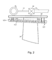
- FIG. 2 shows an enlarged view of a nacelle having a housing portion 120.
- the base frame 40 is included carrying the gear box 34 and the generator 36.
- the gear box is connected to the rotor by a drive train 32 and the generator is connected to the gear box by shaft 33.
- reinforcement bars 122 are provided within the housing 120 of the nacelle.
- the reinforcement bars can be made of steel, a plastic material and/or a natural material. Additionally or alternatively the reinforcement can be provided by a cage. According to further alternatives or additional options hooks, and connections between reinforcing bars can be provided as shown in the area 222.
- connection between the base frame 40 and the nacelle housing 120 can be provided by connecting members 242 which connect a reinforcement portion of the concrete material with the base frame.
- the concrete material of the nacelle housing 120 includes fibers 322 which can be of a steel material, plastic material and/or glass material. Typically the fibers are homogenously but arbitrarily distributed within the concrete material. According to yet further embodiments, a fiber reinforcement can be combined with a re-bar reinforcement that has been described with respect to Fig. 2 .
- reinforced concrete can be used.
- steel or fiber reinforcement in the form of bars (re-bar), meshes or fibers can be utilized.
- fibers can be made of steel, glass, synthetic or natural materials.
- Typical steel reinforced (ferroconcrete) structures may include anchorage like anchor plates or bending of the re-bar, for example into 90 degree bend or 100 degree hook.
- fiber-reinforced plastic re-bar reinforcement can alternatively or additionally used.
- the fiber reinforced concrete can have fiber length of 30 to 80 mm, for example 45 mm, wherein the fiber diameter can be about 1 mm.
- Typical embodiments have a volume fraction of fibers in the concrete from 0.1 to 3 %.
- the concrete nacelle by providing a mesh of glass fibers, plastic fibers or steel fibers and shoot the concrete on the mesh on order to provide a shotcrete nacelle housing.
- the reinforced concrete structures can be pre-stressed in order to better withstand tensile forces.
- concrete can withstand compressive forces.
- pre-stressing the concrete such that a compressive force acts on the concrete without any outside forces, the ability to withstand tensile stress can be improved.
- the pre-stressing can be achieved by using steel tendons or bars that are subjected to a tensile force prior to casting the concrete, in pre-tension concrete, or after concrete has cured, in posed-tension concrete.
- Fig. 4 illustrates embodiments, which are similar to the embodiments described with respect to Fig. 1 and which can be combined with embodiments described with respect to Fig. 2 and 3 .
- a coating 420 can be provided on the outside of the concrete nacelle. Thereby, protection of the concrete nacelle can be achieved.
- the coating system can be of a highly flexible material like liquid synthetic materials, composites or plastics, which are provided on web and/or fabric.
- the thickness of the housing of the wall of the nacelle including concrete material can be in arrange of 1 cm to 10 cm, for example 2 cm.
- a method of manufacturing a structure of a wind turbine including providing reinforced concrete in a structure wall shape; and hardening the concrete may include at least one option from the group of providing the reinforced concrete in conducted by pouring the concrete in a mold including reinforcement therein or shooting the concrete at a structure, frame or web.
- the manufacturing comprising a concrete material can be similarly applied to the spinner/hub of a wind turbine or other kinds of fairings that are applied to the wind turbine.
Landscapes
- Engineering & Computer Science (AREA)
- Life Sciences & Earth Sciences (AREA)
- Sustainable Development (AREA)
- Sustainable Energy (AREA)
- Chemical & Material Sciences (AREA)
- Combustion & Propulsion (AREA)
- Mechanical Engineering (AREA)
- General Engineering & Computer Science (AREA)
- Wind Motors (AREA)
Abstract
A structure of a wind turbine selected 100 from the group consisting of: a nacelle 22 of a wind turbine, a hub 26 of a wind turbine, and fairings of a wind turbine is described. The structure includes a structure housing 120 comprising a concrete material.
Description
- The present invention relates generally to wind turbines. Particularly, it relates to a nacelle of a wind turbine or other structures provided on top of the tower of a wind turbine and methods of manufacturing nacelle and/or other structures of a wind turbine.
- The increasing demand for power generation with wind turbines result in a desire for reducing costs and improving characteristics of components of a wind turbine.
- For example, noise generated by a wind turbine can be partly mechanical. Mechanical noise is generated mainly from rotating machinery in the nacelle, particularly the gear box and the generator. However, there may also be contributions from cooling fans, auxiliary equipment (such as pumps and compressors), bearings and the yaw system. Mechanical noise is often at a plurality of frequencies or a tone which maybe caused by the meshing frequency of a stage of the gear box. Noise emission of the wind turbine should be minimized to an admissible sound pressure level depending on the allowed noise source in a certain location.
- Further, the use of low-cost materials for a component of a wind turbine is desired. Thereby, the production costs of manufacturing a component with a certain material has to be considered.
- In view of the above, according to various aspects of the present invention, there are provided, a structure of a wind turbine, a wind turbine, and a method of manufacturing a structure of a wind turbine.
- According to one embodiment, a structure of a wind turbine selected from the group consisting of: a nacelle of a wind turbine, a hub of a wind turbine, and fairings of a wind turbine is provided. The structure includes a structure housing comprising a concrete material.
- According to another embodiment, a wind turbine having a nacelle or another structure selected from the group consisting of a hub and fairings is provided. The wind turbine includes a structure wall comprising a concrete material.
- According to an even further embodiment, a method of manufacturing a structure of a wind turbine is provided. The method includes providing reinforced concrete in a structure wall shape; and hardening the concrete.
- Various embodiments, aspects, advantages and features are apparent from the appended claims, the description and the accompanying drawings, in which:
-
Fig. 1 shows a schematic view of a portion of a wind turbine having a nacelle with a housing comprising concrete material; -
Fig. 2 shows an enlarged view of the nacelle including the housing of the nacelle according to embodiments described herein; -
Fig. 3 shows an enlarged view of a further nacelle including the housing of the nacelle according to embodiments described herein; and -
Fig. 4 shows a schematic view of a portion of a further wind turbine having a nacelle with a housing comprising concrete material; - Reference will now be made in detail to the various embodiments, one or more examples of which are illustrated in the figures. Each example is provided by way of explanation of the invention and is not meant as a limitation of the invention. For example, features illustrated or described as part of one embodiment can be used on or in conjunction with other embodiments to yield yet a further embodiment. It is intended that the scope of the present invention includes such modifications and variations.
- Modern wind turbines experience and increase in size and rated power. In particular, megawatt and multi-megawatt wind turbines are more commonly installed. Thereby, the increase in size and rated power of the wind turbines also result in an increasing amount of materials required. Accordingly, substituting expensive materials with low-cost materials gets increasingly important.
- According to embodiments described herein, concrete and, in particular reinforced concrete, is used to manufacture the nacelle of wind turbine generator systems.
-
Fig. 1 illustrates embodiments ofwind turbine 100.Fig. 1 shows a portion of a wind turbine, wherein an upper part of thetower 20 is shown. Thenacelle 22 is mounted on thetower 20. Thenacelle 22 carries thehub 26 to which therotor blades 28 are mounted. The rotation of the rotor is transferred to thegear box 34 by thedrive train 32. Thegear box 34 is connected to thegenerator 36 by ashaft 33. These and other components like the yaw drive, a breaking system, a cooling system and electronic devices are provided in thenacelle 22 of thewind turbine 100. - The
nacelle 22 has ahousing portion 120 or a wall, which comprises a concrete material. Thereby, typically reinforced concrete can be used. - According to different embodiments, which can be combined with other embodiments described herein, the concrete nacelle can be reinforced by materials and/or woven materials of the group consisting of, for example, steel, plastic, cotton, glass, mono filament polypropylene, span basalt, synthetic materials, natural materials and combinations thereof.
- According to yet other embodiments, alternatively or additionally steel cages, steel reinforcement bars (re-bar) or other cages and/or bars can be used for reinforcement. Thereby, it is possible to increase the amount of tension force that can be taken by the concrete.
- According to embodiments described herein, concrete as a low-cost material that can easily be brought into nearly any shape can be used for manufacturing the nacelle. Thereby concrete also provides a material which can significantly reduce acoustic emission from the machine head compared to other materials. Additionally, concrete is less inflammable than fiber composite structures like fiber reinforced plastic.
- Generally, according to embodiments described herein, which can be combined with other embodiments described herein, every type of concrete, which may typically be reinforced can be used for manufacturing the housing of a structure from the group consisting of: a nacelle of a wind turbine, a hub of a wind turbine, and fairings of a wind turbine. Thereby, as typical examples, lightweight concrete, air-entrained concrete and/or other types of concrete described herein.
- According to embodiments described herein, concrete as a mixture of cement and water, wherein cementitious materials such us fly ash, slag cement and aggregates can be included is used as a material for the nacelle, in particular the wall of the nacelle housing. Concrete solidifies and hardens after mixing due to hydration. Before hydration, concrete can be brought into any shape and, thus, a nacelle can be easily manufactured.
- According to specific embodiments, refractory cement might be used for providing better ability to withstand elevated temperatures.
- According to yet further embodiments, which can be combined with other embodiments described herein, sand, natural gravel, crushed stones, air-cooled blast furnace slag, ash, remainders from recycling can be used as aggregates in the cement. Further optionally, chemical admixtures like accelerators, air-entrainers, plasticizers and corrosion inhibitors can be added. Additionally or optionally also mineral admixtures like fly ash, slag, silica fume can be adhered for providing the desired material characteristic of the concrete use to manufacture the nacelle. As a further alternative cork-cement may be also be used.
- According to yet further embodiments, in particular, for off-shore applications wherein seawater might have corrosive effects on concrete, porcelain cement and cement using more than 50 % or 60 % of slag as an aggregate can be used to improve the resistance to seawater.
- Further, according to some implementations, high-strength concrete can be used by lowering the water-cement ratio and, optionally at silica fume. Generally, other forms of high-performance concrete (HPC) can be used to improve the characteristics of concrete, for example with regard to long-term mechanically properties, long life in severe environments, permeability, volumes debility, and the like.
- According to yet further embodiments, shotcrete can be used to shoot concrete on to a frame or structure, which might for example be provided by woven material. Thereby a concrete nacelle can be easily manufactured.
- As shown in
Fig. 1 , thenacelle 22 and thebase plate 40 which may according to different embodiments be a single base frame (or bedplate), or which may also have different individual or connected frames like a main frame and a generator frame, are connected to each other by connectingmembers 142. - Other embodiments and details of a concrete material included in a nacelle are shown in
Fig. 2. Fig. 2 shows an enlarged view of a nacelle having ahousing portion 120. Within the nacelle thebase frame 40 is included carrying thegear box 34 and thegenerator 36. As described above, the gear box is connected to the rotor by adrive train 32 and the generator is connected to the gear box byshaft 33. Within thehousing 120 of the nacelle, which includes concrete material, reinforcement bars 122 are provided. Typically, the reinforcement bars can be made of steel, a plastic material and/or a natural material. Additionally or alternatively the reinforcement can be provided by a cage. According to further alternatives or additional options hooks, and connections between reinforcing bars can be provided as shown in thearea 222. - According to some embodiments, which can be combined with other embodiments described herein, the connection between the
base frame 40 and thenacelle housing 120 can be provided by connectingmembers 242 which connect a reinforcement portion of the concrete material with the base frame. - Other embodiments of concrete materials that can be used for manufacturing the
nacelle housing 120 are illustrated with regard toFig. 3 . The concrete material of thenacelle housing 120 includesfibers 322 which can be of a steel material, plastic material and/or glass material. Typically the fibers are homogenously but arbitrarily distributed within the concrete material. According to yet further embodiments, a fiber reinforcement can be combined with a re-bar reinforcement that has been described with respect toFig. 2 . - Generally, concrete has a relatively high compressive strength but lower tensile strength. Thus, as described above, reinforced concrete can be used. Thereby, for example, steel or fiber reinforcement in the form of bars (re-bar), meshes or fibers can be utilized. According to different embodiments, fibers can be made of steel, glass, synthetic or natural materials. Typical steel reinforced (ferroconcrete) structures may include anchorage like anchor plates or bending of the re-bar, for example into 90 degree bend or 100 degree hook. As a further example, fiber-reinforced plastic re-bar reinforcement can alternatively or additionally used.
- According to different embodiments, the fiber reinforced concrete can have fiber length of 30 to 80 mm, for example 45 mm, wherein the fiber diameter can be about 1 mm. Typical embodiments have a volume fraction of fibers in the concrete from 0.1 to 3 %.
- According to yet further embodiments, it is possible to manufacture the concrete nacelle by providing a mesh of glass fibers, plastic fibers or steel fibers and shoot the concrete on the mesh on order to provide a shotcrete nacelle housing.
- According to yet further embodiments, which can be combined with other embodiments described herein, the reinforced concrete structures can be pre-stressed in order to better withstand tensile forces. Generally concrete can withstand compressive forces. By pre-stressing the concrete such that a compressive force acts on the concrete without any outside forces, the ability to withstand tensile stress can be improved. By introducing compressive stress in the concrete material prior to super imposed loads being generated in operation the stress limits in the concrete for both compression attentions can be optimized. Thereby, according to specific examples, the pre-stressing can be achieved by using steel tendons or bars that are subjected to a tensile force prior to casting the concrete, in pre-tension concrete, or after concrete has cured, in posed-tension concrete.
-
Fig. 4 illustrates embodiments, which are similar to the embodiments described with respect toFig. 1 and which can be combined with embodiments described with respect toFig. 2 and3 . Additionally to thenacelle housing 120 being manufactured with concrete materials, acoating 420 can be provided on the outside of the concrete nacelle. Thereby, protection of the concrete nacelle can be achieved. Typically, the coating system can be of a highly flexible material like liquid synthetic materials, composites or plastics, which are provided on web and/or fabric. - Generally, the thickness of the housing of the wall of the nacelle including concrete material can be in arrange of 1 cm to 10 cm, for example 2 cm. By providing modem reinforcement materials, which also allow for a reduced thickness of the wall of the nacelle, the weight increase that might occur in light of the concrete material is limited.
- According to yet further embodiments, which can be combined with other embodiments described herein, a method of manufacturing a structure of a wind turbine including providing reinforced concrete in a structure wall shape; and hardening the concrete, may include at least one option from the group of providing the reinforced concrete in conducted by pouring the concrete in a mold including reinforcement therein or shooting the concrete at a structure, frame or web.
- This written description uses examples to disclose the invention, including the preferred mode, and also to enable any person skilled in the art to make and use the invention. While the invention has been described in terms of various specific embodiments, those skilled in the art will recognize that the invention can be practiced with modifications within the spirit and scope of the claims. Especially, mutually non-exclusive features of the embodiments described above may be combined with each other. The patentable scope of the invention is defined by the claims, and may include other examples that occur to those skilled in the art. Such other examples are intended to be within the scope of the claims if they have structural elements that do not differ from the literal language of the claims, or if they include equivalent structural elements with insubstantial differences from the literal language of the claims.
- According to yet other embodiments, which can be combined with other embodiments described herein, the manufacturing comprising a concrete material can be similarly applied to the spinner/hub of a wind turbine or other kinds of fairings that are applied to the wind turbine.
- Various aspects and embodiments of the present invention are defined by the following numbered clauses:
- 1. A structure of a wind turbine selected from the group consisting of: a nacelle of a wind turbine, a hub of a wind turbine, and fairings of a wind turbine, comprising:
- a structure housing comprising a concrete material.
- 2. The structure of clause 1, wherein the structure is a nacelle of the wind turbine.
- 3. The structure of any preceding clause, wherein the concrete material is reinforced concrete having a reinforcement embedded in the concrete material.
- 4. The structure of any preceding clause, wherein the reinforcement comprises reinforcement bars.
- 5. The structure of any preceding clause, wherein the reinforcement bars consist of a material selected at least from the group consisting of steel, plastics, carbon and combinations thereof.
- 6. The structure of any preceding clause, wherein the reinforcement comprises a cage and/or an anchorage.
- 7. The structure of any preceding clause, wherein the reinforcement comprises fibers comprising at least a material selected from the group consisting of glass fibers, steel fibers, plastic fibers, synthetic fibers, natural fibers, and combinations thereof.
- 8. The structure of any preceding clause, wherein the concrete material is prestressed.
- 9. The structure of any preceding clause, further comprising a coating provided at the outside of the concrete material.
- 10. A wind turbine having a structure selected from the group consisting of a nacelle, a hub, and fairings, the wind turbine comprising:
- a structure wall comprising a concrete material.
- 11. The wind turbine of clause 10, wherein the structure is the nacelle.
- 12. The wind turbine of clause 10 or 11, wherein the concrete material is reinforced concrete having a reinforcement embedded in the concrete material.
- 13. The wind turbine of any of clauses 10 to 12, wherein the reinforcement comprises reinforcement bars.
- 14. The wind turbine of any of clauses 10 to 13, wherein the reinforcement bars consist of a material selected at least from the group consisting of steel, plastics, carbon, and combinations thereof.
- 15. The wind turbine of any of clauses 10 to 14, wherein the concrete can be selected from a group consisting of lightweight concrete and air-entrained concrete.
- 16. The wind turbine of any of clauses 10 to 15, wherein the reinforcement comprises fibers comprising at least a material selected from the group consisting of glass fibers, steel fibers, plastic fibers, synthetic fibers, natural fibers, and combinations thereof.
- 17. The wind turbine of any of clauses 10 to 16 wherein the concrete material is prestressed.
- 18. The wind turbine of any of clauses 10 to 17 further comprising a coating provided at the outside of the concrete material.
- 19. A method of manufacturing a structure of a wind turbine, the method comprising:
- providing reinforced concrete in a structure wall shape; and
- hardening the concrete.
- 20. The method of clause 19, wherein the providing the reinforced concrete in conducted by pouring the concrete in a mold including reinforcement therein or by shooting the concrete at a structure, frame or web.
Claims (10)
- A structure of a wind turbine (100) selected from the group consisting of: a nacelle (22) of a wind turbine, a hub (26) of a wind turbine, and fairings of a wind turbine, comprising:a structure housing (120) comprising a concrete material.
- The structure of claim 1, wherein the concrete material is reinforced concrete having a reinforcement (122, 322) embedded in the concrete material.
- The structure of claim 2, wherein the reinforcement (122,322) comprises reinforcement bars (122).
- The structure of claim 3, wherein the reinforcement bars (122) consist of a material selected at least from the group consisting of steel, plastics, carbon and combinations thereof.
- The structure of any of claims 2 to 4, wherein the reinforcement (122,322) comprises a cage and/or an anchorage.
- The structure of any of claims 2 to 5, wherein the reinforcement (122,322) comprises fibers (322) comprising at least a material selected from the group consisting of glass fibers, steel fibers, plastic fibers, synthetic fibers, natural fibers, and combinations thereof.
- The structure of any of claims 1 to 6, wherein the concrete can be at least one element selected from a group consisting of lightweight concrete, air-entrained concrete, pre-stressed, concrete, and combinations thereof.
- The structure of any of claims 1 to 7, further comprising a coating (420) provided at the outside of the concrete material.
- A wind turbine (100) having a structure according to any of claims 1 to 9.
- A method of manufacturing a structure of a wind turbine (100), the method comprising:providing reinforced concrete in a structure wall shape (120); andhardening the concrete.
Applications Claiming Priority (1)
| Application Number | Priority Date | Filing Date | Title |
|---|---|---|---|
| US12/045,920 US20090232659A1 (en) | 2008-03-11 | 2008-03-11 | Concrete to fabricate the nacelle of a wind turbine |
Publications (1)
| Publication Number | Publication Date |
|---|---|
| EP2108817A2 true EP2108817A2 (en) | 2009-10-14 |
Family
ID=41011949
Family Applications (1)
| Application Number | Title | Priority Date | Filing Date |
|---|---|---|---|
| EP09154478A Withdrawn EP2108817A2 (en) | 2008-03-11 | 2009-03-06 | Concrete to fabricate the nacelle of a wind turbine |
Country Status (3)
| Country | Link |
|---|---|
| US (1) | US20090232659A1 (en) |
| EP (1) | EP2108817A2 (en) |
| CN (1) | CN101532464A (en) |
Cited By (1)
| Publication number | Priority date | Publication date | Assignee | Title |
|---|---|---|---|---|
| WO2011060845A2 (en) | 2009-11-20 | 2011-05-26 | Voith Patent Gmbh | Tidal power plant and method for the construction thereof |
Families Citing this family (7)
| Publication number | Priority date | Publication date | Assignee | Title |
|---|---|---|---|---|
| US20110133472A1 (en) * | 2010-04-20 | 2011-06-09 | Joerg Middendorf | Wind Turbine, Nacelle, And Method Of Assembling Wind Turbine |
| US8203230B2 (en) * | 2010-06-29 | 2012-06-19 | General Electric Company | Yaw bearing system |
| JP2012012980A (en) * | 2010-06-30 | 2012-01-19 | Mitsubishi Heavy Ind Ltd | Wind power generator |
| EP2788621A2 (en) * | 2011-12-06 | 2014-10-15 | Siemens Aktiengesellschaft | Wind turbine |
| CN103987963B (en) * | 2011-12-06 | 2017-11-10 | 西门子公司 | Platen for wind turbines |
| WO2013108079A1 (en) * | 2012-01-18 | 2013-07-25 | Apamsc Austria Gmbh | Wind energy converter components made of ultra high performance concrete |
| CN107387337B (en) * | 2017-09-01 | 2023-03-10 | 三一重能股份有限公司 | Wind driven generator, underframe and construction equipment for manufacturing underframe |
Family Cites Families (7)
| Publication number | Priority date | Publication date | Assignee | Title |
|---|---|---|---|---|
| US5487251A (en) * | 1994-05-06 | 1996-01-30 | Independent Concrete Pipe | Apparatus and method for reinforcing cast structures |
| US6717285B2 (en) * | 2000-09-28 | 2004-04-06 | Michael Ferraro | Multiple collector wind driven power generating device |
| ITBA20020047A1 (en) * | 2002-12-17 | 2004-06-18 | Enertec Aktiegesellschaft Ag | METHOD OF REALIZATION OF A SUBMERSIBLE PUSH-PLATFORM LOCKED FOR THE PRODUCTION OF ELECTRICITY FROM THE WIND IN THE OPEN SEA AND OF MARICULTURE PRODUCTS |
| CA2522185C (en) * | 2003-04-14 | 2012-08-14 | Serwin Holding Aps | Sandwich plate-like construction |
| WO2004099605A2 (en) * | 2003-04-30 | 2004-11-18 | Taylor Ronald J | Wind turbine having airfoils for blocking and directing wind and rotors with or without a central gap |
| US20050051208A1 (en) * | 2003-06-17 | 2005-03-10 | Mount Robert L. | System for transferring heat in a thermoelectric generator system |
| EP1658966A1 (en) * | 2004-11-17 | 2006-05-24 | General Electric Company | Damping material, damping arrangement and method for designing a damping arrangement |
-
2008
- 2008-03-11 US US12/045,920 patent/US20090232659A1/en not_active Abandoned
-
2009
- 2009-03-06 EP EP09154478A patent/EP2108817A2/en not_active Withdrawn
- 2009-03-11 CN CN200910127606A patent/CN101532464A/en active Pending
Cited By (2)
| Publication number | Priority date | Publication date | Assignee | Title |
|---|---|---|---|---|
| WO2011060845A2 (en) | 2009-11-20 | 2011-05-26 | Voith Patent Gmbh | Tidal power plant and method for the construction thereof |
| DE102009053879A1 (en) | 2009-11-20 | 2011-05-26 | Voith Patent Gmbh | Tidal power plant and process for its preparation |
Also Published As
| Publication number | Publication date |
|---|---|
| US20090232659A1 (en) | 2009-09-17 |
| CN101532464A (en) | 2009-09-16 |
Similar Documents
| Publication | Publication Date | Title |
|---|---|---|
| EP2108817A2 (en) | Concrete to fabricate the nacelle of a wind turbine | |
| Jin et al. | Development of lightweight engineered cementitious composite for durability enhancement of tall concrete wind towers | |
| US8511013B2 (en) | Wind turbine tower and system and method for fabricating the same | |
| CN101481930B (en) | Architectural structure of fiber braided mesh composite reinforced concrete and its preparation method | |
| AU2018408668B2 (en) | TRC folded assemble-type permanent formwork and manufacturing method thereof | |
| EP2076642A1 (en) | Polymeric concrete for wind generators towers or other large structural applications | |
| CN210420905U (en) | Hybrid reinforcement structure of seismically damaged bridge piers based on shape memory alloy and carbon fiber cloth | |
| CN114477878A (en) | Fiber concrete | |
| CN113047869A (en) | Tunnel reinforcing structure and method for reinforcing sprayed fiber cement by fiber fabric net | |
| CN107311571A (en) | The preparation method of nanometer enhancing TRC composites | |
| CN108560403A (en) | A kind of concrete column | |
| CN114407189A (en) | Pressure-bearing pipeline for water delivery and distribution and preparation method thereof | |
| Zhu et al. | Freeze—Thaw Behaviours of Half Grouted Sleeve Connections with High-Performance Grout | |
| CN222206963U (en) | FRP rib reinforced concrete composite beam | |
| CN113026796B (en) | Wind power generation tower foundation ring foundation reinforcing structure and method | |
| CN106930587B (en) | Novel pre-stressed cement produced with the dry method silo and reinforcement means | |
| JP3048343B2 (en) | Hollow reinforced concrete pile | |
| CN213268585U (en) | Confined concrete column based on sea sand seawater TRC prefabricated shell | |
| CN108505684A (en) | A kind of high tenacity cement-base composite material permanent column shuttering and production method | |
| CN117231026A (en) | Concrete structure composite reinforcing device and reinforcing method | |
| Raju et al. | Experimentalstudies on Replacement of Steel Stirrups by Sisal Fiber Reinforced Polymers | |
| CN115991585A (en) | A wind power tower tube piece without steel cage and preparation method thereof | |
| CN110282932B (en) | A high-strength and high-toughness cement-based composite material with saturated multi-fracture cracking using coarse river sand as fine aggregate | |
| JP4545667B2 (en) | Floor slab repair method using buried formwork | |
| CN107379363B (en) | Forming process of polymer concrete pipeline |
Legal Events
| Date | Code | Title | Description |
|---|---|---|---|
| PUAI | Public reference made under article 153(3) epc to a published international application that has entered the european phase |
Free format text: ORIGINAL CODE: 0009012 |
|
| AK | Designated contracting states |
Kind code of ref document: A2 Designated state(s): AT BE BG CH CY CZ DE DK EE ES FI FR GB GR HR HU IE IS IT LI LT LU LV MC MK MT NL NO PL PT RO SE SI SK TR |
|
| AX | Request for extension of the european patent |
Extension state: AL BA RS |
|
| STAA | Information on the status of an ep patent application or granted ep patent |
Free format text: STATUS: THE APPLICATION IS DEEMED TO BE WITHDRAWN |
|
| 18D | Application deemed to be withdrawn |
Effective date: 20121002 |