EP2108806A1 - Gas turbine engine systems involving variable nozzles with sliding doors - Google Patents
Gas turbine engine systems involving variable nozzles with sliding doors Download PDFInfo
- Publication number
- EP2108806A1 EP2108806A1 EP09250923A EP09250923A EP2108806A1 EP 2108806 A1 EP2108806 A1 EP 2108806A1 EP 09250923 A EP09250923 A EP 09250923A EP 09250923 A EP09250923 A EP 09250923A EP 2108806 A1 EP2108806 A1 EP 2108806A1
- Authority
- EP
- European Patent Office
- Prior art keywords
- door
- nozzle
- operative
- exit area
- nozzle assembly
- Prior art date
- Legal status (The legal status is an assumption and is not a legal conclusion. Google has not performed a legal analysis and makes no representation as to the accuracy of the status listed.)
- Granted
Links
Images
Classifications
-
- F—MECHANICAL ENGINEERING; LIGHTING; HEATING; WEAPONS; BLASTING
- F02—COMBUSTION ENGINES; HOT-GAS OR COMBUSTION-PRODUCT ENGINE PLANTS
- F02K—JET-PROPULSION PLANTS
- F02K3/00—Plants including a gas turbine driving a compressor or a ducted fan
- F02K3/02—Plants including a gas turbine driving a compressor or a ducted fan in which part of the working fluid by-passes the turbine and combustion chamber
- F02K3/04—Plants including a gas turbine driving a compressor or a ducted fan in which part of the working fluid by-passes the turbine and combustion chamber the plant including ducted fans, i.e. fans with high volume, low pressure outputs, for augmenting the jet thrust, e.g. of double-flow type
- F02K3/077—Plants including a gas turbine driving a compressor or a ducted fan in which part of the working fluid by-passes the turbine and combustion chamber the plant including ducted fans, i.e. fans with high volume, low pressure outputs, for augmenting the jet thrust, e.g. of double-flow type the plant being of the multiple flow type, i.e. having three or more flows
-
- F—MECHANICAL ENGINEERING; LIGHTING; HEATING; WEAPONS; BLASTING
- F02—COMBUSTION ENGINES; HOT-GAS OR COMBUSTION-PRODUCT ENGINE PLANTS
- F02K—JET-PROPULSION PLANTS
- F02K1/00—Plants characterised by the form or arrangement of the jet pipe or nozzle; Jet pipes or nozzles peculiar thereto
- F02K1/06—Varying effective area of jet pipe or nozzle
-
- F—MECHANICAL ENGINEERING; LIGHTING; HEATING; WEAPONS; BLASTING
- F02—COMBUSTION ENGINES; HOT-GAS OR COMBUSTION-PRODUCT ENGINE PLANTS
- F02K—JET-PROPULSION PLANTS
- F02K1/00—Plants characterised by the form or arrangement of the jet pipe or nozzle; Jet pipes or nozzles peculiar thereto
- F02K1/06—Varying effective area of jet pipe or nozzle
- F02K1/08—Varying effective area of jet pipe or nozzle by axially moving or transversely deforming an internal member, e.g. the exhaust cone
Definitions
- the disclosure generally relates to gas turbine engines.
- Varying the nozzle exhaust area of a gas turbine engine can affect engine performance.
- varying the nozzle exhaust area can alter propulsive efficiency, fan stability, noise output, and/or fuel consumption.
- an exemplary embodiment of a door assembly for a gas turbine engine comprises: a door configured for alignment with an exit area of a nozzle and operative to variably open and close the nozzle exit area such that gas directed along a gas path defined, at least in part, by the nozzle exit area is regulated.
- An exemplary embodiment of a nozzle assembly for a gas turbine engine comprises: a nozzle defining a nozzle exit area; and a door operative to selectively increase and decrease an effective size of the nozzle exit area.
- An exemplary embodiment of a gas turbine engine comprises: a compressor; a turbine operative to drive the compressor; and a nozzle assembly positioned downstream of the turbine, the nozzle assembly defining an exit area and having a door operative to move between an open position, at which the nozzle assembly exhibits a maximum exit area, and a closed position, at which the nozzle assembly exhibits a minimum exit area.
- Gas turbine engine systems involving variable nozzles with sliding doors are provided, several exemplary embodiments of which will be described in detail.
- a sliding door is moved fore and aft in a gas turbine engine to vary the nozzle exhaust area of the engine dynamically. Varying the nozzle exhaust area in a gas turbine engine can increase engine performance characteristics such as fuel efficiency.
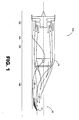
- FIG. 1 is a schematic diagram depicting an exemplary embodiment of a gas turbine engine 100 in which a nozzle assembly 10 that incorporates a sliding door can be used to operatively vary the exit area 14 of the nozzle assembly 10 and affect engine performance.
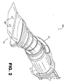
- FIG. 2 is a cross-sectional perspective diagram of the gas turbine engine depicted in FIG. 1 .
- the gas turbine engine 100 includes a compressor section 102, a combustion section 104, a turbine section 106, and an exhaust section 108.
- engine 100 is a turbofan engine, there is no intention to limit the concepts to use with turbofan engines as other types of gas turbine engines can be used.
- the exhaust section 108 of gas turbine engine 100 includes nozzle assembly 10, which defines an exit area 14.
- gas is routed along a gas path 26, which passes through duct 16 to the nozzle assembly 10, and then out of the nozzle assembly via exit area 14.
- Performance of the gas turbine engine 100 can be affected by regulating gas directed along gas path 26 by influencing the gas in a vicinity of the exit area 14.
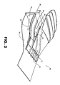
- FIG. 3 depicts nozzle assembly 10 and the incorporated sliding door 12.
- sliding door 12 is configured to be translated across exit area 14 and thereby influence gas directed along gas path 26.
- the nozzle assembly is a third stream exhaust nozzle that is operative to regulate gas accelerated by a tertiary fan (e.g., a tip fan located radially outboard of a fan stage).
- a tertiary fan e.g., a tip fan located radially outboard of a fan stage.
- a third stream nozzle helps enable the engine variable cycle.
- the third stream duct experiences increased backpressure and the fan air normally flowing into the third stream duct diverts into the secondary/primary flow stream.
- the flow streams communicate just aft of the fan.
- a third stream splitter which can be located several inches aft of the fan, for example, leaves a large enough area for effective flow stream communication.
- a nozzle assembly can be used for varying the flow characteristics of gas directed along one or more other gas paths.
- the sliding door 12 is configured to be variably positioned along a range of positions between a full open position, at which the nozzle assembly 10 exhibits a maximum exit area, and a full closed position, at which the nozzle assembly 10 exhibits a minimum exit area. As the sliding door 12 is variably positioned, gas directed along gas path 26 is regulated.
- sliding door 12 exhibits a low section area relative to a direction of travel associated with gas directed along gas path stream 26. Such a configuration and orientation tends to result in a low actuation load, i.e., the load required to be overcome for positioning of the door.
- the nozzle assembly 10 also incorporates an actuator 20 that engages sliding door 12.
- the actuator 20 is attached to the sliding door 12 and is configured to operatively translate the sliding door 12 in both a fore and aft direction, as indicated by arrows 18.
- the actuator 20 can be an air motor driven direct actuated ball screw ram, direct actuated hydraulic ram, and air or hydraulic driven mechanisms.
- Actuator 20 may be singular or a plurality of synchronized actuators.
- the actuator 20 includes air motor driven direct actuated ball screw rams (such as linear motion cylindrical actuators or rotary motion actuators), synchronized via flex drive cables (a commonly used actuation configuration in various commercial nacelle reverser cowlings).
- the actuator 20 can be located unobtrusively in an area 30 of the nozzle assembly 10 between gas path 26 and a core path 24.
- a nozzle assembly can also incorporate a pressurized plenum.
- a pressurized plenum can be configured to provide pressure balancing to the nozzle assembly thereby reducing actuation loads. If the loads are predicted to be reacted primarily by the tracks, a plenum may not be required. However, when a plenum is utilized (such as in association with area 30 in this embodiment), the plenum can be a direct acting plenum placed, for example, on the forward facing face of the door. Alternatively, a remote balance chamber can be utilized.
- the nozzle assembly 10 also incorporates a rail 22 for the sliding door 12.
- the rail 22 facilitates the translation of the sliding door 12.
- the rail 22 provides a track on which the sliding door 12 is translated.
- the rail 22 also is configured to provide alignment and structural stability to the sliding door 12.
- more than one rail 22 is utilized.
- the rail 22 includes one or more bearings to facilitate a smoother translation of the sliding door 12 along the rail 22.
- the tracks of the rail 22 can be embedded in the fixed structure ahead of the door 12, and/or along sides of the door, such that that door 12 is cantilevered aft and the tracks are hidden from the flowpath.
- the nozzle assembly 10 also incorporates a plurality of stiffening ribs 28 to control deflection of the sliding door as the sliding door 12 is variably opened and closed. For example, as the sliding door 12 is variably closed, pressure increases within the duct 16.
- the plurality of stiffening ribs 28 also provides structural support to the sliding door 12 as the door translates across the exit area 14 of the nozzle assembly 10.
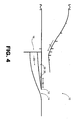
- FIG. 4 is a schematic diagram depicting the nozzle assembly 10 of FIG 3 .
- the gas path 26 includes passage through duct 16, the nozzle assembly 10 and exit area 14.
- the actuator 20 is connected to the sliding door 12 and is configured to operatively translate the sliding door 12 in both a fore and aft direction, as indicated by arrows 18, thus varying the exit area 14 of the nozzle assembly 10.
- the sliding door 12 is variably opened and closed, by translating in both a fore and aft direction, as indicated by arrows 18.
- more complex motion of the sliding door can be used. Regardless of the particular motion involved, positioning of the door varies the exit area 14 of the nozzle assembly 10 and thereby affects one or more of various engine performance characteristics.
- a sliding door can be configured to alter a nozzle throat asymmetrically in order to affect yaw vectoring of the flow. In some embodiments, this can be accomplished by the use of differential actuation of multiple actuators. All such modifications and variations are intended to be included herein within the scope of this disclosure and protected by the accompanying claims.
Landscapes
- Engineering & Computer Science (AREA)
- Chemical & Material Sciences (AREA)
- Combustion & Propulsion (AREA)
- Mechanical Engineering (AREA)
- General Engineering & Computer Science (AREA)
- Control Of Turbines (AREA)
- Supercharger (AREA)
Abstract
Description
- The disclosure generally relates to gas turbine engines.
- Varying the nozzle exhaust area of a gas turbine engine can affect engine performance. By way of example, varying the nozzle exhaust area can alter propulsive efficiency, fan stability, noise output, and/or fuel consumption.
- Gas turbine engine systems involving variable nozzles with sliding doors are provided. In this regard, an exemplary embodiment of a door assembly for a gas turbine engine comprises: a door configured for alignment with an exit area of a nozzle and operative to variably open and close the nozzle exit area such that gas directed along a gas path defined, at least in part, by the nozzle exit area is regulated.
- An exemplary embodiment of a nozzle assembly for a gas turbine engine comprises: a nozzle defining a nozzle exit area; and a door operative to selectively increase and decrease an effective size of the nozzle exit area.
- An exemplary embodiment of a gas turbine engine comprises: a compressor; a turbine operative to drive the compressor; and a nozzle assembly positioned downstream of the turbine, the nozzle assembly defining an exit area and having a door operative to move between an open position, at which the nozzle assembly exhibits a maximum exit area, and a closed position, at which the nozzle assembly exhibits a minimum exit area.
- Other systems, methods, features and/or advantages of this disclosure will be or may become apparent to one with skill in the art upon examination of the following drawings and detailed description. It is intended that all such additional systems, methods, features and/or advantages be included within this description and be within the scope of the present disclosure.
- Many aspects of the disclosure can be better understood with reference to the following drawings. The components in the drawings are not necessarily to scale. Moreover, in the drawings, like reference numerals designate corresponding parts throughout the several views.
-
FIG. 1 is a schematic diagram depicting an exemplary embodiment of a gas turbine engine. -
FIG. 2 is a cross-sectional perspective diagram of the gas turbine engine ofFIG. 1 . -
FIG. 3 is a perspective diagram depicting an exemplary embodiment of a nozzle assembly. -
FIG. 4 is a schematic diagram depicting the sliding door of the embodiment ofFIG. 3 in a planar view. - Gas turbine engine systems involving variable nozzles with sliding doors are provided, several exemplary embodiments of which will be described in detail. In some embodiments, such a sliding door is moved fore and aft in a gas turbine engine to vary the nozzle exhaust area of the engine dynamically. Varying the nozzle exhaust area in a gas turbine engine can increase engine performance characteristics such as fuel efficiency.
-
FIG. 1 is a schematic diagram depicting an exemplary embodiment of agas turbine engine 100 in which anozzle assembly 10 that incorporates a sliding door can be used to operatively vary theexit area 14 of thenozzle assembly 10 and affect engine performance.FIG. 2 is a cross-sectional perspective diagram of the gas turbine engine depicted inFIG. 1 . As shown in bothFIG. 1 andFIG 2 , thegas turbine engine 100 includes acompressor section 102, acombustion section 104, aturbine section 106, and anexhaust section 108. It should be noted that althoughengine 100 is a turbofan engine, there is no intention to limit the concepts to use with turbofan engines as other types of gas turbine engines can be used. - The
exhaust section 108 ofgas turbine engine 100 includesnozzle assembly 10, which defines anexit area 14. In operation, gas is routed along agas path 26, which passes throughduct 16 to thenozzle assembly 10, and then out of the nozzle assembly viaexit area 14. Performance of thegas turbine engine 100 can be affected by regulating gas directed alonggas path 26 by influencing the gas in a vicinity of theexit area 14. - In this regard, reference is made to the perspective diagram of
FIG. 3 , which depictsnozzle assembly 10 and the incorporated slidingdoor 12. As shown inFIG. 3 , slidingdoor 12 is configured to be translated acrossexit area 14 and thereby influence gas directed alonggas path 26. In at least one embodiment, the nozzle assembly is a third stream exhaust nozzle that is operative to regulate gas accelerated by a tertiary fan (e.g., a tip fan located radially outboard of a fan stage). A third stream nozzle helps enable the engine variable cycle. By way of example, by closing the third stream nozzle area, the third stream duct experiences increased backpressure and the fan air normally flowing into the third stream duct diverts into the secondary/primary flow stream. Notably, the flow streams communicate just aft of the fan. A third stream splitter, which can be located several inches aft of the fan, for example, leaves a large enough area for effective flow stream communication. However, in other embodiments, a nozzle assembly can be used for varying the flow characteristics of gas directed along one or more other gas paths. - The sliding
door 12 is configured to be variably positioned along a range of positions between a full open position, at which thenozzle assembly 10 exhibits a maximum exit area, and a full closed position, at which thenozzle assembly 10 exhibits a minimum exit area. As the slidingdoor 12 is variably positioned, gas directed alonggas path 26 is regulated. - In the embodiment of
FIG. 3 , slidingdoor 12 exhibits a low section area relative to a direction of travel associated with gas directed alonggas path stream 26. Such a configuration and orientation tends to result in a low actuation load, i.e., the load required to be overcome for positioning of the door. In this regard, thenozzle assembly 10 also incorporates anactuator 20 that engages slidingdoor 12. Theactuator 20 is attached to the slidingdoor 12 and is configured to operatively translate the slidingdoor 12 in both a fore and aft direction, as indicated byarrows 18. - By way of example, the
actuator 20 can be an air motor driven direct actuated ball screw ram, direct actuated hydraulic ram, and air or hydraulic driven mechanisms.Actuator 20 may be singular or a plurality of synchronized actuators. For example, theactuator 20 includes air motor driven direct actuated ball screw rams (such as linear motion cylindrical actuators or rotary motion actuators), synchronized via flex drive cables (a commonly used actuation configuration in various commercial nacelle reverser cowlings). Theactuator 20 can be located unobtrusively in anarea 30 of thenozzle assembly 10 betweengas path 26 and acore path 24. - In some embodiments, a nozzle assembly can also incorporate a pressurized plenum. Such a pressurized plenum can be configured to provide pressure balancing to the nozzle assembly thereby reducing actuation loads. If the loads are predicted to be reacted primarily by the tracks, a plenum may not be required. However, when a plenum is utilized (such as in association with
area 30 in this embodiment), the plenum can be a direct acting plenum placed, for example, on the forward facing face of the door. Alternatively, a remote balance chamber can be utilized. - The
nozzle assembly 10 also incorporates arail 22 for the slidingdoor 12. Therail 22 facilitates the translation of the slidingdoor 12. In particular, therail 22 provides a track on which thesliding door 12 is translated. Therail 22 also is configured to provide alignment and structural stability to the slidingdoor 12. In at least one embodiment, more than onerail 22 is utilized. In other embodiments, therail 22 includes one or more bearings to facilitate a smoother translation of the slidingdoor 12 along therail 22. In yet another embodiment, the tracks of therail 22 can be embedded in the fixed structure ahead of thedoor 12, and/or along sides of the door, such that thatdoor 12 is cantilevered aft and the tracks are hidden from the flowpath. - The
nozzle assembly 10 also incorporates a plurality ofstiffening ribs 28 to control deflection of the sliding door as the slidingdoor 12 is variably opened and closed. For example, as the slidingdoor 12 is variably closed, pressure increases within theduct 16. The plurality ofstiffening ribs 28, located behind the interior wall of theduct 16, reduces deflection of the interior wall. The plurality ofstiffening ribs 28 also provides structural support to the slidingdoor 12 as the door translates across theexit area 14 of thenozzle assembly 10. -
FIG. 4 is a schematic diagram depicting thenozzle assembly 10 ofFIG 3 . As shown inFIG 4 , thegas path 26 includes passage throughduct 16, thenozzle assembly 10 andexit area 14. - The
actuator 20 is connected to the slidingdoor 12 and is configured to operatively translate the slidingdoor 12 in both a fore and aft direction, as indicated byarrows 18, thus varying theexit area 14 of thenozzle assembly 10. In operation, the slidingdoor 12 is variably opened and closed, by translating in both a fore and aft direction, as indicated byarrows 18. In other embodiments, more complex motion of the sliding door can be used. Regardless of the particular motion involved, positioning of the door varies theexit area 14 of thenozzle assembly 10 and thereby affects one or more of various engine performance characteristics. - It should be emphasized that the above-described embodiments are merely possible examples of implementations set forth for a clear understanding of the principles of this disclosure. Many variations and modifications may be made to the above-described embodiments without departing substantially from the principles of the disclosure. By way of example, in some embodiments, a sliding door can be configured to alter a nozzle throat asymmetrically in order to affect yaw vectoring of the flow. In some embodiments, this can be accomplished by the use of differential actuation of multiple actuators. All such modifications and variations are intended to be included herein within the scope of this disclosure and protected by the accompanying claims.
Claims (14)
- A door assembly for a gas turbine engine, the door assembly compnsmg:a door (12) configured for alignment with an exit area (14) of a nozzle and operative to variably open and close the nozzle exit area (14) such that gas directed along a gas path (26) defined, at least in part, by the nozzle exit area (14) is regulated.
- A nozzle assembly (10) for a gas turbine engine, the nozzle assembly (10) comprising:a nozzle defining a nozzle exit area (14); anda door (12) operative to selectively increase and decrease an effective size of the nozzle exit area (14).
- A gas turbine engine (100) comprising:a compressor (102);a turbine (106) operative to drive the compressor; anda nozzle assembly positioned downstream of the turbine (106), the nozzle assembly (10) defining an exit area (14) and having a door (12) operative to move between an open position, at which the nozzle assembly (10) exhibits a maximum exit area (14), and a closed position, at which the nozzle assembly exhibits a minimum exit area (14).
- The invention of any preceding claim, further comprising an actuator (20) connected to the door (12) and operative to position or translate the door (12) whereby, for example, the nozzle exit area (14) is altered or the effective size of the nozzle exit area is established.
- The invention of claim 4, wherein the actuator (20) is operative to translate the door (12) in both fore and aft directions.
- The invention of any preceding claim, wherein the nozzle assembly (10) is a third stream exhaust nozzle assembly.
- The invention of any preceding claim, further comprising at least one stiffening rib (28) operative to provide structural support to the door (12), said rib optionally contacting the door (12).
- The invention of any preceding claim, wherein the at least one stiffening rib (28) is located on a non-gas path side of the door (12).
- The invention of any preceding claim, further comprising a rail (22) operative to provide alignment of the door (12).
- The invention of any of claims 1 to 8, further comprising:a rail (22) operative to engage the door (12) such that engagement of the door (12) and the rail (22) facilitates alignment of the door (12) with the nozzle exit area (14).
- The invention of any of claims 1 to 8, further comprising:a rail (22) engaging the door (12) and operative to provide alignment of the door (12) during positioning.
- The invention of any preceding claim, wherein the engine (100) is a turbofan gas turbine engine.
- The invention of any preceding claim, wherein the door (12) is operative to symmetrically affect the gas path with respect to yaw.
- The invention of any preceding claim, further comprising a plenum located on a non-gas path side of the door (12), the plenum being operative to pressurize in order to reduce an actuation load of the door (12).
Applications Claiming Priority (1)
| Application Number | Priority Date | Filing Date | Title |
|---|---|---|---|
| US12/100,470 US8356483B2 (en) | 2008-04-10 | 2008-04-10 | Gas turbine engine systems involving variable nozzles with sliding doors |
Publications (2)
| Publication Number | Publication Date |
|---|---|
| EP2108806A1 true EP2108806A1 (en) | 2009-10-14 |
| EP2108806B1 EP2108806B1 (en) | 2012-09-12 |
Family
ID=40897660
Family Applications (1)
| Application Number | Title | Priority Date | Filing Date |
|---|---|---|---|
| EP09250923A Ceased EP2108806B1 (en) | 2008-04-10 | 2009-03-30 | Gas turbine engine systems involving variable nozzles with sliding doors |
Country Status (2)
| Country | Link |
|---|---|
| US (1) | US8356483B2 (en) |
| EP (1) | EP2108806B1 (en) |
Cited By (1)
| Publication number | Priority date | Publication date | Assignee | Title |
|---|---|---|---|---|
| EP2519729A4 (en) * | 2009-12-29 | 2014-12-31 | Rolls Royce Nam Tech Inc | Exhaust for a gas turbine engine |
Families Citing this family (14)
| Publication number | Priority date | Publication date | Assignee | Title |
|---|---|---|---|---|
| ATE523682T1 (en) * | 2005-09-27 | 2011-09-15 | Volvo Aero Corp | ARRANGEMENT FOR DRIVING AN AIRCRAFT, AIRCRAFT AND EXHAUST NOZZLE FOR A JET ENGINE |
| US9115669B2 (en) | 2011-10-28 | 2015-08-25 | United Technologies Corporation | Gas turbine engine exhaust nozzle cooling valve |
| US9140212B2 (en) | 2012-06-25 | 2015-09-22 | United Technologies Corporation | Gas turbine engine with reverse-flow core having a bypass flow splitter |
| US20140161603A1 (en) * | 2012-12-07 | 2014-06-12 | General Electric Company | Exhaust diffuser |
| US10400621B2 (en) | 2013-03-04 | 2019-09-03 | United Technologies Corporation | Pivot door thrust reverser with variable area nozzle |
| US9856824B2 (en) * | 2013-03-07 | 2018-01-02 | Rolls-Royce North American Technologies Inc. | Aircraft nozzle system |
| US9863366B2 (en) * | 2013-03-13 | 2018-01-09 | Rolls-Royce North American Technologies Inc. | Exhaust nozzle apparatus and method for multi stream aircraft engine |
| US9523329B2 (en) | 2013-03-15 | 2016-12-20 | United Technologies Corporation | Gas turbine engine with stream diverter |
| US9009966B2 (en) | 2013-03-15 | 2015-04-21 | Northrop Gurmman Systems Corporation | Internal/external single expansion ramp nozzle with integrated third stream |
| US9957823B2 (en) | 2014-01-24 | 2018-05-01 | United Technologies Corporation | Virtual multi-stream gas turbine engine |
| US10309318B2 (en) | 2014-12-02 | 2019-06-04 | United Technologies Corporation | Turbomachine flow diverting device and method |
| US10190506B2 (en) | 2014-12-02 | 2019-01-29 | United Technologies Corporation | Turbomachine bypass flow diverting assembly and method |
| US11339744B1 (en) | 2020-02-07 | 2022-05-24 | Rolls-Royce North American Technologies Inc. | Pressure equalization in a dual flow path exhaust of a hypersonic propulsion system |
| US11339745B1 (en) | 2020-02-07 | 2022-05-24 | Rolls-Royce North American Technologies Inc. | Dual flowpath exhaust for fuel cooling in a hypersonic propulsion system |
Citations (7)
| Publication number | Priority date | Publication date | Assignee | Title |
|---|---|---|---|---|
| DE1081277B (en) | 1958-08-16 | 1960-05-05 | Johann Endres Dr Ing | Dual-flow combustion chamber for gas turbines, especially gas turbine jet engines |
| GB862405A (en) | 1958-04-04 | 1961-03-08 | John Alan Courtney Hyde | Variable area jet propulsion nozzle |
| FR2184021A1 (en) | 1972-05-09 | 1973-12-21 | Rolls Royce | |
| US3841091A (en) | 1973-05-21 | 1974-10-15 | Gen Electric | Multi-mission tandem propulsion system |
| CA1029201A (en) | 1974-06-12 | 1978-04-11 | Augustus M. Helmintoller (Jr.) | Nozzle and auxiliary inlet arrangement for gas turbine engine |
| FR2499158A1 (en) | 1981-02-05 | 1982-08-06 | Snecma | Residual efflux control for gas turbine - has internal and external vanes on tailpipe to control secondary air discharge |
| EP1619376A2 (en) | 2004-07-23 | 2006-01-25 | General Electric Company | Split shroud exhaust nozzle |
Family Cites Families (20)
| Publication number | Priority date | Publication date | Assignee | Title |
|---|---|---|---|---|
| US2737015A (en) | 1948-05-07 | 1956-03-06 | Pratt & Whitney Co Inc | Jet engine control |
| US3386658A (en) * | 1965-12-08 | 1968-06-04 | Usa | Convergent-divergent jet exhaust nozzle for supersonic aircraft |
| US3449914A (en) * | 1967-12-21 | 1969-06-17 | United Aircraft Corp | Variable flow turbofan engine |
| US4068469A (en) * | 1975-05-29 | 1978-01-17 | The United States Of America As Represented By The Administrator Of The National Aeronautics And Space Administration | Variable thrust nozzle for quiet turbofan engine and method of operating same |
| US4175384A (en) * | 1977-08-02 | 1979-11-27 | General Electric Company | Individual bypass injector valves for a double bypass variable cycle turbofan engine |
| US5694767A (en) * | 1981-11-02 | 1997-12-09 | General Electric Company | Variable slot bypass injector system |
| US5307624A (en) * | 1990-04-04 | 1994-05-03 | General Electric Company | Variable area bypass valve assembly |
| US5778659A (en) | 1994-10-20 | 1998-07-14 | United Technologies Corporation | Variable area fan exhaust nozzle having mechanically separate sleeve and thrust reverser actuation systems |
| US5893518A (en) | 1995-11-30 | 1999-04-13 | United Technologies Corporation | Attachment means for flaps of variable exhaust nozzle |
| US5833140A (en) | 1996-12-12 | 1998-11-10 | United Technologies Corporation | Variable geometry exhaust nozzle for a turbine engine |
| US6318070B1 (en) | 2000-03-03 | 2001-11-20 | United Technologies Corporation | Variable area nozzle for gas turbine engines driven by shape memory alloy actuators |
| US6938408B2 (en) | 2001-04-26 | 2005-09-06 | Propulsion Vectoring, L.P. | Thrust vectoring and variable exhaust area for jet engine nozzle |
| GB0205701D0 (en) | 2002-03-12 | 2002-04-24 | Rolls Royce Plc | Variable area nozzle |
| US7093793B2 (en) | 2003-08-29 | 2006-08-22 | The Nordam Group, Inc. | Variable cam exhaust nozzle |
| US6901739B2 (en) * | 2003-10-07 | 2005-06-07 | General Electric Company | Gas turbine engine with variable pressure ratio fan system |
| US7216476B2 (en) | 2003-12-09 | 2007-05-15 | The Boeing Company | Two-axis thrust vectoring nozzle |
| US7140174B2 (en) * | 2004-09-30 | 2006-11-28 | General Electric Company | Methods and apparatus for assembling a gas turbine engine |
| US7134271B2 (en) | 2004-11-05 | 2006-11-14 | General Electric Company | Thrust vectoring aft FLADE engine |
| US20070018034A1 (en) | 2005-07-12 | 2007-01-25 | Dickau John E | Thrust vectoring |
| US7770381B2 (en) * | 2006-12-18 | 2010-08-10 | General Electric Company | Duct burning mixed flow turbofan and method of operation |
-
2008
- 2008-04-10 US US12/100,470 patent/US8356483B2/en not_active Expired - Fee Related
-
2009
- 2009-03-30 EP EP09250923A patent/EP2108806B1/en not_active Ceased
Patent Citations (7)
| Publication number | Priority date | Publication date | Assignee | Title |
|---|---|---|---|---|
| GB862405A (en) | 1958-04-04 | 1961-03-08 | John Alan Courtney Hyde | Variable area jet propulsion nozzle |
| DE1081277B (en) | 1958-08-16 | 1960-05-05 | Johann Endres Dr Ing | Dual-flow combustion chamber for gas turbines, especially gas turbine jet engines |
| FR2184021A1 (en) | 1972-05-09 | 1973-12-21 | Rolls Royce | |
| US3841091A (en) | 1973-05-21 | 1974-10-15 | Gen Electric | Multi-mission tandem propulsion system |
| CA1029201A (en) | 1974-06-12 | 1978-04-11 | Augustus M. Helmintoller (Jr.) | Nozzle and auxiliary inlet arrangement for gas turbine engine |
| FR2499158A1 (en) | 1981-02-05 | 1982-08-06 | Snecma | Residual efflux control for gas turbine - has internal and external vanes on tailpipe to control secondary air discharge |
| EP1619376A2 (en) | 2004-07-23 | 2006-01-25 | General Electric Company | Split shroud exhaust nozzle |
Cited By (1)
| Publication number | Priority date | Publication date | Assignee | Title |
|---|---|---|---|---|
| EP2519729A4 (en) * | 2009-12-29 | 2014-12-31 | Rolls Royce Nam Tech Inc | Exhaust for a gas turbine engine |
Also Published As
| Publication number | Publication date |
|---|---|
| US8356483B2 (en) | 2013-01-22 |
| EP2108806B1 (en) | 2012-09-12 |
| US20090255269A1 (en) | 2009-10-15 |
Similar Documents
| Publication | Publication Date | Title |
|---|---|---|
| EP2108806A1 (en) | Gas turbine engine systems involving variable nozzles with sliding doors | |
| US11454193B2 (en) | Gas turbine engine with axial movable fan variable area nozzle | |
| JP5241215B2 (en) | Passive guidance system and method for aircraft engine nozzle fluids | |
| US8443585B2 (en) | Thrust reversing variable area nozzle | |
| US9551298B2 (en) | Variable area fan nozzle with one or more integrated blocker doors | |
| US8074440B2 (en) | Gas turbine engine with axial movable fan variable area nozzle | |
| US7600371B2 (en) | Thrust reversers including support members for inhibiting deflection | |
| US9410500B2 (en) | Movable cascade turbojet thrust reverser having translatable reverser cowl causing variation in jet nozzle | |
| US10975804B2 (en) | Translating outer cowl flow modulation device and method | |
| BRPI0713507A2 (en) | thrust reverser for a turbine engine nacelle and turbine engine nacelle | |
| US10570853B2 (en) | Thrust reverser assembly | |
| US9255546B2 (en) | Cascade-style variable area fan duct nozzle | |
| US20120109593A1 (en) | Gas turbine engine with variable area fan nozzle | |
| US20210189959A1 (en) | Aircraft comprising a gas turbine engine having an intake and a nacelle | |
| US11293377B2 (en) | Turbojet engine nacelle including a cascade thrust reverser | |
| EP2987991B1 (en) | Fan nozzle with thrust reversing and variable area function | |
| US20100132367A1 (en) | Device for moving a plurality of hatches in a gas turbine engine | |
| JP2008196492A (en) | Relief device for turbojet engine and turbojet engine equipped with the relief device | |
| US20090241550A1 (en) | Gas Turbine Engine Systems Involving Variable Nozzles with Flexible Panels | |
| EP4467792A3 (en) | Aircraft propulsion system with variable area inlet | |
| US11913403B2 (en) | Door thrust reverser comprising a deflector for redirecting an air flow in the upstream direction | |
| US20220290632A1 (en) | Aircraft thrust reverser comprising a braking mechanism for slowing a mobile cowl in the event of overtravel | |
| JP2013519823A (en) | Articulated slider track |
Legal Events
| Date | Code | Title | Description |
|---|---|---|---|
| PUAI | Public reference made under article 153(3) epc to a published international application that has entered the european phase |
Free format text: ORIGINAL CODE: 0009012 |
|
| AK | Designated contracting states |
Kind code of ref document: A1 Designated state(s): AT BE BG CH CY CZ DE DK EE ES FI FR GB GR HR HU IE IS IT LI LT LU LV MC MK MT NL NO PL PT RO SE SI SK TR |
|
| AX | Request for extension of the european patent |
Extension state: AL BA RS |
|
| 17P | Request for examination filed |
Effective date: 20091123 |
|
| 17Q | First examination report despatched |
Effective date: 20091218 |
|
| AKX | Designation fees paid |
Designated state(s): DE GB |
|
| GRAP | Despatch of communication of intention to grant a patent |
Free format text: ORIGINAL CODE: EPIDOSNIGR1 |
|
| GRAS | Grant fee paid |
Free format text: ORIGINAL CODE: EPIDOSNIGR3 |
|
| GRAA | (expected) grant |
Free format text: ORIGINAL CODE: 0009210 |
|
| AK | Designated contracting states |
Kind code of ref document: B1 Designated state(s): DE GB |
|
| REG | Reference to a national code |
Ref country code: GB Ref legal event code: FG4D |
|
| GRAL | Information related to payment of fee for publishing/printing deleted |
Free format text: ORIGINAL CODE: EPIDOSDIGR3 |
|
| GRAS | Grant fee paid |
Free format text: ORIGINAL CODE: EPIDOSNIGR3 |
|
| REG | Reference to a national code |
Ref country code: DE Ref legal event code: R096 Ref document number: 602009009678 Country of ref document: DE Effective date: 20121108 |
|
| PLBE | No opposition filed within time limit |
Free format text: ORIGINAL CODE: 0009261 |
|
| STAA | Information on the status of an ep patent application or granted ep patent |
Free format text: STATUS: NO OPPOSITION FILED WITHIN TIME LIMIT |
|
| 26N | No opposition filed |
Effective date: 20130613 |
|
| REG | Reference to a national code |
Ref country code: DE Ref legal event code: R097 Ref document number: 602009009678 Country of ref document: DE Effective date: 20130613 |
|
| REG | Reference to a national code |
Ref country code: DE Ref legal event code: R082 Ref document number: 602009009678 Country of ref document: DE Representative=s name: SCHMITT-NILSON SCHRAUD WAIBEL WOHLFROM PATENTA, DE |
|
| REG | Reference to a national code |
Ref country code: DE Ref legal event code: R082 Ref document number: 602009009678 Country of ref document: DE Representative=s name: SCHMITT-NILSON SCHRAUD WAIBEL WOHLFROM PATENTA, DE Ref country code: DE Ref legal event code: R081 Ref document number: 602009009678 Country of ref document: DE Owner name: UNITED TECHNOLOGIES CORP. (N.D.GES.D. STAATES , US Free format text: FORMER OWNER: UNITED TECHNOLOGIES CORP., HARTFORD, CONN., US |
|
| REG | Reference to a national code |
Ref country code: DE Ref legal event code: R081 Ref document number: 602009009678 Country of ref document: DE Owner name: RAYTHEON TECHNOLOGIES CORPORATION (N.D.GES.D.S, US Free format text: FORMER OWNER: UNITED TECHNOLOGIES CORP. (N.D.GES.D. STAATES DELAWARE), FARMINGTON, CONN., US |
|
| P01 | Opt-out of the competence of the unified patent court (upc) registered |
Effective date: 20230519 |
|
| PGFP | Annual fee paid to national office [announced via postgrant information from national office to epo] |
Ref country code: DE Payment date: 20240220 Year of fee payment: 16 Ref country code: GB Payment date: 20240220 Year of fee payment: 16 |
|
| REG | Reference to a national code |
Ref country code: DE Ref legal event code: R119 Ref document number: 602009009678 Country of ref document: DE |
|
| GBPC | Gb: european patent ceased through non-payment of renewal fee |
Effective date: 20250330 |
|
| PG25 | Lapsed in a contracting state [announced via postgrant information from national office to epo] |
Ref country code: DE Free format text: LAPSE BECAUSE OF NON-PAYMENT OF DUE FEES Effective date: 20251001 |
|
| PG25 | Lapsed in a contracting state [announced via postgrant information from national office to epo] |
Ref country code: GB Free format text: LAPSE BECAUSE OF NON-PAYMENT OF DUE FEES Effective date: 20250330 |