EP2108566A1 - Assembly comprising a chassis and a child seat being detachably connectable to the chassis, such a chassis as well as such a child seat - Google Patents
Assembly comprising a chassis and a child seat being detachably connectable to the chassis, such a chassis as well as such a child seat Download PDFInfo
- Publication number
- EP2108566A1 EP2108566A1 EP09004950A EP09004950A EP2108566A1 EP 2108566 A1 EP2108566 A1 EP 2108566A1 EP 09004950 A EP09004950 A EP 09004950A EP 09004950 A EP09004950 A EP 09004950A EP 2108566 A1 EP2108566 A1 EP 2108566A1
- Authority
- EP
- European Patent Office
- Prior art keywords
- chassis
- child seat
- pivot arm
- pawl
- connecting elements
- Prior art date
- Legal status (The legal status is an assumption and is not a legal conclusion. Google has not performed a legal analysis and makes no representation as to the accuracy of the status listed.)
- Granted
Links
Images


Classifications
-
- B—PERFORMING OPERATIONS; TRANSPORTING
- B62—LAND VEHICLES FOR TRAVELLING OTHERWISE THAN ON RAILS
- B62B—HAND-PROPELLED VEHICLES, e.g. HAND CARTS OR PERAMBULATORS; SLEDGES
- B62B7/00—Carriages for children; Perambulators, e.g. dolls' perambulators
- B62B7/04—Carriages for children; Perambulators, e.g. dolls' perambulators having more than one wheel axis; Steering devices therefor
- B62B7/14—Carriages for children; Perambulators, e.g. dolls' perambulators having more than one wheel axis; Steering devices therefor with detachable or rotatably-mounted body
- B62B7/142—Means for securing the body to the frame
-
- B—PERFORMING OPERATIONS; TRANSPORTING
- B60—VEHICLES IN GENERAL
- B60N—SEATS SPECIALLY ADAPTED FOR VEHICLES; VEHICLE PASSENGER ACCOMMODATION NOT OTHERWISE PROVIDED FOR
- B60N2/00—Seats specially adapted for vehicles; Arrangement or mounting of seats in vehicles
- B60N2/24—Seats specially adapted for vehicles; Arrangement or mounting of seats in vehicles for particular purposes or particular vehicles
- B60N2/26—Seats specially adapted for vehicles; Arrangement or mounting of seats in vehicles for particular purposes or particular vehicles for children
- B60N2/28—Seats readily mountable on, and dismountable from, existing seats or other parts of the vehicle
- B60N2/2842—Seats readily mountable on, and dismountable from, existing seats or other parts of the vehicle adapted to carry the child, when dismounted from the vehicle
- B60N2/2848—Seats readily mountable on, and dismountable from, existing seats or other parts of the vehicle adapted to carry the child, when dismounted from the vehicle being convertible or adaptable to a preambulator, e.g. a baby-carriage or a push-chair
-
- B—PERFORMING OPERATIONS; TRANSPORTING
- B62—LAND VEHICLES FOR TRAVELLING OTHERWISE THAN ON RAILS
- B62B—HAND-PROPELLED VEHICLES, e.g. HAND CARTS OR PERAMBULATORS; SLEDGES
- B62B7/00—Carriages for children; Perambulators, e.g. dolls' perambulators
- B62B7/04—Carriages for children; Perambulators, e.g. dolls' perambulators having more than one wheel axis; Steering devices therefor
- B62B7/14—Carriages for children; Perambulators, e.g. dolls' perambulators having more than one wheel axis; Steering devices therefor with detachable or rotatably-mounted body
- B62B7/145—Carriages for children; Perambulators, e.g. dolls' perambulators having more than one wheel axis; Steering devices therefor with detachable or rotatably-mounted body the body being a rigid seat, e.g. a shell
-
- B—PERFORMING OPERATIONS; TRANSPORTING
- B62—LAND VEHICLES FOR TRAVELLING OTHERWISE THAN ON RAILS
- B62B—HAND-PROPELLED VEHICLES, e.g. HAND CARTS OR PERAMBULATORS; SLEDGES
- B62B2205/00—Hand-propelled vehicles or sledges being foldable or dismountable when not in use
- B62B2205/20—Catches; Locking or releasing an articulation
Definitions
- Assembly comprising a chassis and a child seat being detachably connectable to the chassis, such a chassis as well as such a child seat.
- the invention relates to an assembly comprising a chassis and a child seat being detachably connectable to the chassis, which child seat is provided with at least one first connecting element, which is detachably connectable to a second connecting element provided in the chassis, said connecting elements being provided with a locking mechanism for interlocking the connecting elements, which locking mechanism can be unlocked for subsequently disconnecting the connecting elements from each other.
- the invention also relates to a chassis and a child seat suitable for such an assembly.
- a child seat is provided with two pin-shaped elements, which can each be positioned in tubular elements connected to the chassis.
- the tubular element is provided with a cam which is movable against spring force, which cam can be brought into engagement with a recess formed in said pin-shaped element for locking the child seat in position relative to the chassis.
- the chassis used in said German utility model is a stroller.
- Removing the child seat from the chassis is thus a comparatively complex operation.
- the object of the invention is to provide an assembly which enables a user to remove the child seat from the chassis in a simple manner.
- This object is accomplished with the assembly according to the invention in that the locking mechanism can be locked in a blocking position, in which position the locking mechanism is unlocked.
- a user can move the locking mechanism to the blocking position with one hand, after which the child seat is still connected to the chassis but no longer interlocked with the chassis. The user will then no longer need that hand for holding the locking mechanism in the unlocked position, since the locking mechanism is in the blocking position. In other words, an external force is no longer needed for holding the locking mechanism in the unlocked position. After the locking mechanism has been unlocked and moved to the blocking position, the user has both hands available for disconnecting the child seat from the chassis.
- the serviceability of the assembly is enhanced.
- the safety of a child seated in the child seat is enhanced, since the user has both hands available for taking hold of the child seat.
- a user can unlock and disconnect the child seat from the chassis with one hand, if desired.
- One embodiment of the assembly according to the invention is characterised in that the child seat is provided with first connecting elements located on two longitudinal sides, whilst the chassis is provided with two spaced-apart second connecting elements, which can be connected to said first connecting elements, and the locking mechanisms can be locked in the blocking positions in succession.
- the first connecting element is provided with a pivot arm, which comprises at least a first and a second hook-shaped element, which elements mate with a first and a second pawl of the second connecting element, whilst the first hook-shaped element is connectable to the first pawl for locking the pivot arm in position and the second hook-shaped element is connectable to the second pawl for locking the pivot arm in the blocking position.
- Yet another embodiment of the assembly according to the invention is characterised in that the second pawl comprises a part that extends conically from the first pawl.
- Such a pawl is comparatively easy to produce.
- pivot arm is pivotable about a substantially horizontally extending pivot axis for connecting the pivot arm to the first pawl, whilst it is also pivotable about a substantially vertically extending second pivot axis for moving the pivot arm to the blocking position.
- pivot arm is pivotable both about a substantially horizontally extending pivot axis and about a substantially vertically extending pivot axis, different kinds of movement of the pivot arm can be realised in a simple manner.
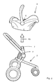
- Figures 1 and 2 show an assembly 1 according to the invention, which comprises a stroller 2 forming a chassis and a child seat 3 detachably connected to the stroller 2.
- the child seat 3 comprises a seat portion 4 and a carrying handle 5, which is connected to the seat portion 4 on either side of the seat portion 4.
- Such a child seat 3 is known per se and will not be explained in more detail herein, therefore.
- the child seat 3 is provided with first connecting elements 6, which mate with second connecting elements 7 provided in the stroller 2.
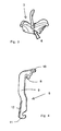
- Figure 3 is a side view of the child seat 3 with the first connecting element 6 illustrated in dotted lines.
- the first connecting element 6 comprises an elongated pivot arm 9 which is pivotable about a horizontally extending pivot axis 8, which pivot arm is provided, at a first end thereof, with a control knob 10, which can be operated on a side of the child seat 3 that faces the carrying handle 5.
- the pivot arm 9 is provided with a first hook-shaped element 11 at a second end located on a side remote from said first end and also with an elongated rib 12, which extends transversely to the pivot arm 9.
- the rib 12 forms a second hook-shaped element.
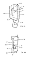
- Figures 5a and 5b are a perspective side view and a perspective top plan view, respectively, of the second connecting element 7, which is connected to a rod 13 of the frame of the stroller 2.
- the second connecting element 7 comprises a carrier plate 14 and two side walls 15 extending transversely to the carrier plate 14.
- the side walls 15 are interconnected at a bottom side by a side wall 16 extending substantially transversely thereto.
- the carrier plate 14 is furthermore provided with two pawls 17, 18.
- the first pawl 17 has a downwardly inclined surface 19 and an engagement surface that faces towards the side wall 16.
- the surfaces 19 and 20 extend transversely to the carrier plate 14.
- the second pawl 18 comprises a part 21 that extends conically from the first pawl 17, which part merges into a wall 23 extending substantially transversely to the carrier plate 14 via a sharp transition 22 on a side remote from the first pawl 17.
- the wall 23 extends substantially vertically.
- the first connecting elements 6 present on either side of the child seat 3 are placed between the side walls 15 of the second connecting elements 7.
- the underside of the first hook-shaped element 11 slides over the wall part 19, whilst the pivot arm 9 is pivoted in a direction indicated by the arrow P11 against spring force until the hook-shaped element 11 has moved over the entire part 19 and engages the engagement surface 20 of the first hook-shaped element 17 under spring force.
- the first connecting element 6 is now interlocked with the second connecting element 7 by the first hook-shaped element 11, which is in engagement with the engagement surface 20.
- the child seat 3 is now securely connected to the stroller 2 and cannot undesirably become detached therefrom.
- the user When a user wishes to remove the child seat 3 from the stroller 2, for example for using the child seat 3 as a separate child seat or using it in a vehicle, for example a car, the user will take hold of the carrying handle 5 with one hand.
- the user will push the control knob 10 in the direction indicated by the arrow P1 (see figures 1 and 7b ) with the other hand, causing the pivot arm 9 to pivot in the direction indicated by the arrow P11 about the pivot axis 8, resulting in the first hook-shaped element 11 being disconnected from the engagement surface 20.
- the pivot arm 9 will also rotate in the direction indicated by the arrow P12 about a vertically extending axis of rotation.
- the user will operate the pivot arm 9 located on the other longitudinal side by moving the control knob 10 in the direction indicated by the arrow P2.
- the rib 12 of this pivot arm 9 has been moved into engagement with the associated wall 23 as well, the child seat 3 can be lifted from the stroller 2 in the direction indicated by the arrow P3.
- the pivot arm 9 is pivotable in the direction indicated by the arrow P11 about the pivot axis 8 with some play, as a result of which the pivot arm 9 is at the same time rotatable in the direction indicated by the arrow P 12 through an angle large enough for moving the pivot arm 9 over the conically extending part 21.
Landscapes
- Engineering & Computer Science (AREA)
- Transportation (AREA)
- Mechanical Engineering (AREA)
- Chemical & Material Sciences (AREA)
- Combustion & Propulsion (AREA)
- Health & Medical Sciences (AREA)
- Child & Adolescent Psychology (AREA)
- General Health & Medical Sciences (AREA)
- Aviation & Aerospace Engineering (AREA)
- Carriages For Children, Sleds, And Other Hand-Operated Vehicles (AREA)
- Seats For Vehicles (AREA)
Abstract
Description
- Assembly comprising a chassis and a child seat being detachably connectable to the chassis, such a chassis as well as such a child seat.
- The invention relates to an assembly comprising a chassis and a child seat being detachably connectable to the chassis, which child seat is provided with at least one first connecting element, which is detachably connectable to a second connecting element provided in the chassis, said connecting elements being provided with a locking mechanism for interlocking the connecting elements, which locking mechanism can be unlocked for subsequently disconnecting the connecting elements from each other.
- The invention also relates to a chassis and a child seat suitable for such an assembly.
- In such an assembly, which is known from German utility model
DE-U1-20.2005.008.211 - As a result of said locking engagement of the child seat, the child seat is securely connected to the chassis. The chassis used in said German utility model is a stroller.
- When a user wishes to remove the child seat from the stroller, the cams present on either side of the stroller must be simultaneously moved out of engagement with the recesses against spring force, after which the pin-shaped elements of the child seat can be lifted from the tubular elements. In order to do so, a user needs three hands, as it were, two for releasing the locking engagement on either side and one for lifting the child seat from the chassis.
- Removing the child seat from the chassis is thus a comparatively complex operation.
- The object of the invention is to provide an assembly which enables a user to remove the child seat from the chassis in a simple manner.
- This object is accomplished with the assembly according to the invention in that the locking mechanism can be locked in a blocking position, in which position the locking mechanism is unlocked.
- A user can move the locking mechanism to the blocking position with one hand, after which the child seat is still connected to the chassis but no longer interlocked with the chassis. The user will then no longer need that hand for holding the locking mechanism in the unlocked position, since the locking mechanism is in the blocking position. In other words, an external force is no longer needed for holding the locking mechanism in the unlocked position. After the locking mechanism has been unlocked and moved to the blocking position, the user has both hands available for disconnecting the child seat from the chassis.
- In this way the serviceability of the assembly is enhanced. In addition, the safety of a child seated in the child seat is enhanced, since the user has both hands available for taking hold of the child seat. Furthermore, a user can unlock and disconnect the child seat from the chassis with one hand, if desired.
- One embodiment of the assembly according to the invention is characterised in that the child seat is provided with first connecting elements located on two longitudinal sides, whilst the chassis is provided with two spaced-apart second connecting elements, which can be connected to said first connecting elements, and the locking mechanisms can be locked in the blocking positions in succession.
- By using connecting elements provided on both longitudinal sides of the child seat, a secure connection with the chassis is obtained. Since the locking mechanisms can be moved to the blocking position in succession, a user can hold the child seat with one hand, whilst the user unlocks and blocks the locking mechanisms in succession with the other hand.
- This enhances the safety of the child seated in the child seat.
- Another embodiment of the assembly according to the invention is characterised in that the first connecting element is provided with a pivot arm, which comprises at least a first and a second hook-shaped element, which elements mate with a first and a second pawl of the second connecting element, whilst the first hook-shaped element is connectable to the first pawl for locking the pivot arm in position and the second hook-shaped element is connectable to the second pawl for locking the pivot arm in the blocking position.
- In this way connecting, locking, unlocking and blocking are realised in a simple manner.
- Yet another embodiment of the assembly according to the invention is characterised in that the second pawl comprises a part that extends conically from the first pawl.
- Such a pawl is comparatively easy to produce.
- Another embodiment of the invention is characterised in that the pivot arm is pivotable about a substantially horizontally extending pivot axis for connecting the pivot arm to the first pawl, whilst it is also pivotable about a substantially vertically extending second pivot axis for moving the pivot arm to the blocking position.
- Since the pivot arm is pivotable both about a substantially horizontally extending pivot axis and about a substantially vertically extending pivot axis, different kinds of movement of the pivot arm can be realised in a simple manner.
- The invention will now be explained in more detail with reference to the drawing, in which:
-
Figure 1 is a perspective view of a child seat connected to a stroller; -
Figure 2 is a perspective view of a child seat disconnected from the stroller; -
Figure 3 is a side view of the child seat shown infigure 2 ; -
Figure 4 is a larger-scale detail view of the pivot arm of the child seat offigure 3 ; -
Figures 5a and 5b are a perspective side view and a perspective top plan view, respectively, of the second connecting element of the stroller shown infigures 1 and2 ; -
Figures 6a and 6b are a perspective top plan view and a perspective side view, respectively, of interlocked first and second connecting elements; -
Figures 7a and 7b are a perspective top plan view and a perspective side view, respectively, of interconnected connecting elements, with the locking mechanism being locked in a blocking position. - Like parts are indicated by the same numerals in the figures.
-
Figures 1 and2 show anassembly 1 according to the invention, which comprises astroller 2 forming a chassis and achild seat 3 detachably connected to thestroller 2. Thechild seat 3 comprises aseat portion 4 and acarrying handle 5, which is connected to theseat portion 4 on either side of theseat portion 4. Such achild seat 3 is known per se and will not be explained in more detail herein, therefore. On both longitudinal sides, thechild seat 3 is provided with first connectingelements 6, which mate with second connectingelements 7 provided in thestroller 2. - The first and second connecting
elements figures 3-7b . -
Figure 3 is a side view of thechild seat 3 with the first connectingelement 6 illustrated in dotted lines. - As
figure 4 clearly shows, the first connectingelement 6 comprises anelongated pivot arm 9 which is pivotable about a horizontally extendingpivot axis 8, which pivot arm is provided, at a first end thereof, with acontrol knob 10, which can be operated on a side of thechild seat 3 that faces thecarrying handle 5. Thepivot arm 9 is provided with a first hook-shaped element 11 at a second end located on a side remote from said first end and also with anelongated rib 12, which extends transversely to thepivot arm 9. Therib 12 forms a second hook-shaped element. -
Figures 5a and 5b are a perspective side view and a perspective top plan view, respectively, of the second connectingelement 7, which is connected to arod 13 of the frame of thestroller 2. The second connectingelement 7 comprises acarrier plate 14 and twoside walls 15 extending transversely to thecarrier plate 14. Theside walls 15 are interconnected at a bottom side by aside wall 16 extending substantially transversely thereto. Thecarrier plate 14 is furthermore provided with twopawls first pawl 17 has a downwardlyinclined surface 19 and an engagement surface that faces towards theside wall 16. Thesurfaces carrier plate 14. - The
second pawl 18 comprises apart 21 that extends conically from thefirst pawl 17, which part merges into awall 23 extending substantially transversely to thecarrier plate 14 via asharp transition 22 on a side remote from thefirst pawl 17. Thewall 23 extends substantially vertically. - The operation of the connecting
elements figures 6a-7b . - Upon placement of the
child seat 3 on thestroller 2 forming a chassis, the first connectingelements 6 present on either side of thechild seat 3 are placed between theside walls 15 of the second connectingelements 7. During said placement, the underside of the first hook-shaped element 11 slides over thewall part 19, whilst thepivot arm 9 is pivoted in a direction indicated by the arrow P11 against spring force until the hook-shaped element 11 has moved over theentire part 19 and engages theengagement surface 20 of the first hook-shaped element 17 under spring force. The first connectingelement 6 is now interlocked with the second connectingelement 7 by the first hook-shaped element 11, which is in engagement with theengagement surface 20. Thechild seat 3 is now securely connected to thestroller 2 and cannot undesirably become detached therefrom. - When a user wishes to remove the
child seat 3 from thestroller 2, for example for using thechild seat 3 as a separate child seat or using it in a vehicle, for example a car, the user will take hold of thecarrying handle 5 with one hand. The user will push thecontrol knob 10 in the direction indicated by the arrow P1 (seefigures 1 and7b ) with the other hand, causing thepivot arm 9 to pivot in the direction indicated by the arrow P11 about thepivot axis 8, resulting in the first hook-shaped element 11 being disconnected from theengagement surface 20. During said pivoting of thepivot arm 9 about thepivot axis 8, thepivot arm 9 will also rotate in the direction indicated by the arrow P12 about a vertically extending axis of rotation. Said rotation takes place in that thepivot arm 9 is moved over the conically extendingpart 21. Thepivot arm 9 is pivoted in the direction indicated by the arrows P11, P12 until therib 12 is located beyond thetransition 22 of the conically extendingpart 21 and is moved in the opposite direction of the arrow P12 under spring force, with therib 12 abutting against thewall 23. Thepivot arm 9 now takes up a blocking position, in which thepivot arm 9 of thefirst pawl 17 of the second connectingelement 7 is unlocked. - After the
pivot arm 9 located on one longitudinal side of thechild seat 3 has been unlocked and blocked, the user will operate thepivot arm 9 located on the other longitudinal side by moving thecontrol knob 10 in the direction indicated by the arrow P2. After therib 12 of thispivot arm 9 has been moved into engagement with the associatedwall 23 as well, thechild seat 3 can be lifted from thestroller 2 in the direction indicated by the arrow P3. - If the
control knob 10 is depressed only little, so that therib 12 is not moved past thetransition 22 of theconically extending part 21, the first hook-shapedelement 11 of thepivot arm 9 will be moved into engagement with theengagement surface 20 again under spring force. - The
pivot arm 9 is pivotable in the direction indicated by the arrow P11 about thepivot axis 8 with some play, as a result of which thepivot arm 9 is at the same time rotatable in the direction indicated by thearrow P 12 through an angle large enough for moving thepivot arm 9 over the conically extendingpart 21.
Claims (8)
- An assembly comprising a chassis and a child seat being detachably connectable to the chassis, which child seat is provided with at least one first connecting element, which is detachably connectable to a second connecting element provided in the chassis, said connecting elements being provided with a locking mechanism for interlocking the connecting elements, which locking mechanism can be unlocked for subsequently disconnecting the connecting elements from each other, characterised in that the locking mechanism can be locked in a blocking position, in which position the locking mechanism is unlocked.
- An assembly according to claim 1, characterised in that the child seat is provided with first connecting elements located on two longitudinal sides, whilst the chassis is provided with two spaced-apart second connecting elements, which can be connected to said first connecting elements, and the locking mechanisms can be locked in the blocking positions in succession.
- An assembly according to claim 1 or 2, characterised in that the first connecting element is provided with a pivot arm, which comprises at least a first and a second hook-shaped element, which elements mate with a first and a second pawl of the second connecting element, whilst the first hook-shaped element is connectable to the first pawl for locking the pivot arm in position and the second hook-shaped element is connectable to the second pawl for locking the pivot arm in the blocking position.
- An assembly according to claim 3, characterised in that the second pawl comprises a part that extends conically from the first pawl.
- An assembly according to claim 3 or 4, characterised in that the pivot arm is pivotable about a substantially horizontally extending pivot axis for connecting the pivot arm to the first pawl, whilst it is also pivotable about a substantially vertically extending second pivot axis for moving the pivot arm to the blocking position.
- A chassis suitable for an assembly according to any one of the preceding claims.
- A chassis according to claim 6, characterised in that the chassis is a stroller.
- A child seat suitable for an assembly according to any one of the preceding claims.
Applications Claiming Priority (1)
| Application Number | Priority Date | Filing Date | Title |
|---|---|---|---|
| NL1035275A NL1035275C2 (en) | 2008-04-09 | 2008-04-09 | Assembly comprising an undercarriage and a child's seat that can be detachably connected to the undercarriage, such an undercarriage as well as such a child's seat. |
Publications (2)
| Publication Number | Publication Date |
|---|---|
| EP2108566A1 true EP2108566A1 (en) | 2009-10-14 |
| EP2108566B1 EP2108566B1 (en) | 2014-05-07 |
Family
ID=40030371
Family Applications (1)
| Application Number | Title | Priority Date | Filing Date |
|---|---|---|---|
| EP09004950.3A Active EP2108566B1 (en) | 2008-04-09 | 2009-04-03 | Assembly comprising a chassis and a child seat being detachably connectable to the chassis, such a chassis as well as such a child seat |
Country Status (4)
| Country | Link |
|---|---|
| US (1) | US8033555B2 (en) |
| EP (1) | EP2108566B1 (en) |
| ES (1) | ES2468556T3 (en) |
| NL (1) | NL1035275C2 (en) |
Cited By (6)
| Publication number | Priority date | Publication date | Assignee | Title |
|---|---|---|---|---|
| GB2482413A (en) * | 2010-07-26 | 2012-02-01 | Wonderland Nursery Goods | Latch mechanism for a removable child carrier on a stroller frame |
| WO2014023767A1 (en) * | 2012-08-07 | 2014-02-13 | Martin Straus | Auxiliary device for a baby carrier |
| EP2813412A1 (en) * | 2013-06-13 | 2014-12-17 | Wonderland Nurserygoods Company Limited | Connection mechanism and infant care equipment having the connection mechanism |
| DE102011112798B4 (en) * | 2010-09-10 | 2016-03-03 | Bp Children's Products Hk Co., Ltd. | Baby Seat |
| NL2023470B1 (en) | 2019-07-10 | 2021-02-02 | Maxi Miliaan Bv | Coupling mechanism as well as a child seat transporting system provided with at least one such a coupling mechanism |
| NL2023469B1 (en) | 2019-07-10 | 2021-02-02 | Maxi Miliaan Bv | Child seat transporting system and safety part suitable for such a child seat transporting system |
Families Citing this family (30)
| Publication number | Priority date | Publication date | Assignee | Title |
|---|---|---|---|---|
| GB2449999B (en) * | 2007-06-06 | 2009-08-05 | Wonderland Nursery Goods | Stroller and seat assembly mechanism for a stroller |
| CN101952156B (en) | 2007-11-01 | 2013-04-03 | 智高美国股份有限公司 | Pushchair Actuation System |
| US8282119B1 (en) * | 2007-12-26 | 2012-10-09 | Kristina Caksa | Two-level travel stroller for children |
| EP2323888B1 (en) * | 2008-08-15 | 2015-01-21 | Artsana Usa Inc. | Stroller |
| TWI402194B (en) * | 2009-07-10 | 2013-07-21 | Nuna Int Bv | Carts |
| CN101954922A (en) * | 2009-07-16 | 2011-01-26 | 中山市隆成日用制品有限公司 | Detachable seat structure of a baby carriage |
| CN201792891U (en) * | 2009-08-05 | 2011-04-13 | 明门香港股份有限公司 | Baby carriage |
| JP2011079514A (en) * | 2009-09-11 | 2011-04-21 | Phil & Teds Most Excellent Buggy Co Ltd | Child carrying push-car, modular support system and component |
| CN102530047B (en) * | 2010-12-20 | 2013-11-27 | 明门香港股份有限公司 | baby carrier |
| AU337036S (en) * | 2011-01-12 | 2011-06-08 | Jane | Baby stroller |
| CN202624323U (en) * | 2012-04-20 | 2012-12-26 | 明门(中国)幼童用品有限公司 | Baby carriage |
| USD699633S1 (en) * | 2012-09-07 | 2014-02-18 | Combi Corporation | Twin stroller |
| USD737733S1 (en) * | 2013-01-11 | 2015-09-01 | Wonderland Nurserygoods Company Limited | Stroller |
| US9480343B2 (en) * | 2013-06-14 | 2016-11-01 | Wonderland Nurserygoods Company Limited | Child high chair |
| US9756961B2 (en) | 2013-06-14 | 2017-09-12 | Wonderland Nurserygoods Company Limited | Adjusting mechanism and related child carrier |
| CN203996350U (en) | 2014-01-10 | 2014-12-10 | 克斯克管理公司 | Foldable go-cart |
| CA157864S (en) * | 2014-02-06 | 2015-07-28 | Stokke As | Baby stroller chassis |
| JP1527799S (en) | 2014-06-30 | 2015-06-29 | ||
| US9260039B1 (en) | 2014-11-06 | 2016-02-16 | Phil Satterfield | Car seat device |
| GB201420312D0 (en) * | 2014-11-14 | 2014-12-31 | Silver Cross Holdings Ltd | Carrier Mounting |
| US10960913B2 (en) | 2016-07-27 | 2021-03-30 | Kolcraft Enterprises, Inc. | Foldable strollers and related methods |
| CN109715473B (en) | 2016-07-27 | 2022-03-04 | 考可拉夫特公司 | Stroller with removable seat and related method |
| US10994763B2 (en) * | 2016-07-27 | 2021-05-04 | Kolcraft Enterprises, Inc. | Foldable strollers with removeable seats and related methods |
| US10058192B2 (en) * | 2016-10-06 | 2018-08-28 | Wonderland Switzerland Ag | Child restraint seat |
| CN109689472B (en) | 2017-07-27 | 2021-10-08 | 考可拉夫特公司 | frame for stroller |
| US10737593B1 (en) | 2018-07-02 | 2020-08-11 | Summer Infant (Usa), Inc. | Car seat |
| USD869996S1 (en) * | 2018-09-12 | 2019-12-17 | Dongguan Crown Shin Baby Appliances Co., Ltd. | Stroller |
| US11376999B2 (en) | 2019-07-10 | 2022-07-05 | Dorel Juvenile Group, Inc. | Infant carrier |
| US11623549B2 (en) | 2019-07-25 | 2023-04-11 | Dorel Juvenile Group, Inc. | Infant carrier |
| CN114802407A (en) * | 2021-01-28 | 2022-07-29 | 明门瑞士股份有限公司 | Fixing device, and passenger device and carrier device using the same |
Citations (3)
| Publication number | Priority date | Publication date | Assignee | Title |
|---|---|---|---|---|
| EP1211124A1 (en) * | 2000-11-24 | 2002-06-05 | Combi Corporation | Child car seat and baby carriage |
| EP1470986A2 (en) | 2003-04-21 | 2004-10-27 | Combi Corporation | Child car seat |
| DE202005008211U1 (en) | 2005-02-02 | 2005-10-06 | Lan, Red, Hsichih | Stroller with a removable seat element |
Family Cites Families (5)
| Publication number | Priority date | Publication date | Assignee | Title |
|---|---|---|---|---|
| US6237995B1 (en) * | 1999-06-03 | 2001-05-29 | Stroll-N-Go Child Products, Inc. | Carseat and stroller with folding linkage system |
| US6595583B2 (en) * | 2001-07-20 | 2003-07-22 | Link Treasure Ltd. | Latch mechanism for stroller seat |
| US7017921B2 (en) * | 2002-11-18 | 2006-03-28 | Evenflo Company, Inc. | Stroller with retaining mechanism |
| TW200533536A (en) * | 2004-02-19 | 2005-10-16 | Combi Corp | Locking mechanism of child car seat and child car seat securing apparatus of stroller |
| NL1031213C2 (en) * | 2006-02-22 | 2007-08-24 | Maxi Miliaan Bv | Stroller. |
-
2008
- 2008-04-09 NL NL1035275A patent/NL1035275C2/en not_active IP Right Cessation
-
2009
- 2009-04-03 ES ES09004950.3T patent/ES2468556T3/en active Active
- 2009-04-03 EP EP09004950.3A patent/EP2108566B1/en active Active
- 2009-04-08 US US12/420,626 patent/US8033555B2/en active Active
Patent Citations (3)
| Publication number | Priority date | Publication date | Assignee | Title |
|---|---|---|---|---|
| EP1211124A1 (en) * | 2000-11-24 | 2002-06-05 | Combi Corporation | Child car seat and baby carriage |
| EP1470986A2 (en) | 2003-04-21 | 2004-10-27 | Combi Corporation | Child car seat |
| DE202005008211U1 (en) | 2005-02-02 | 2005-10-06 | Lan, Red, Hsichih | Stroller with a removable seat element |
Cited By (11)
| Publication number | Priority date | Publication date | Assignee | Title |
|---|---|---|---|---|
| GB2482413A (en) * | 2010-07-26 | 2012-02-01 | Wonderland Nursery Goods | Latch mechanism for a removable child carrier on a stroller frame |
| CN102372021A (en) * | 2010-07-26 | 2012-03-14 | 明门香港股份有限公司 | Latch mechanism and baby carriage including the latch mechanism |
| CN102372021B (en) * | 2010-07-26 | 2013-09-18 | 明门香港股份有限公司 | Latch mechanism and baby carriage including the latch mechanism |
| GB2482413B (en) * | 2010-07-26 | 2017-04-05 | Wonderland Nursery Goods | Latch mechanism and stroller including the same |
| DE102011112798B4 (en) * | 2010-09-10 | 2016-03-03 | Bp Children's Products Hk Co., Ltd. | Baby Seat |
| WO2014023767A1 (en) * | 2012-08-07 | 2014-02-13 | Martin Straus | Auxiliary device for a baby carrier |
| EP2813412A1 (en) * | 2013-06-13 | 2014-12-17 | Wonderland Nurserygoods Company Limited | Connection mechanism and infant care equipment having the connection mechanism |
| US9840168B2 (en) | 2013-06-13 | 2017-12-12 | Wonderland Switzerland Ag | Connection mechanism |
| EP3403900A1 (en) * | 2013-06-13 | 2018-11-21 | Wonderland Switzerland AG | Connection mechanism and infant care equipment having the connection mechanism |
| NL2023470B1 (en) | 2019-07-10 | 2021-02-02 | Maxi Miliaan Bv | Coupling mechanism as well as a child seat transporting system provided with at least one such a coupling mechanism |
| NL2023469B1 (en) | 2019-07-10 | 2021-02-02 | Maxi Miliaan Bv | Child seat transporting system and safety part suitable for such a child seat transporting system |
Also Published As
| Publication number | Publication date |
|---|---|
| US20090256323A1 (en) | 2009-10-15 |
| EP2108566B1 (en) | 2014-05-07 |
| US8033555B2 (en) | 2011-10-11 |
| ES2468556T3 (en) | 2014-06-16 |
| NL1035275C2 (en) | 2009-10-12 |
Similar Documents
| Publication | Publication Date | Title |
|---|---|---|
| EP2108566B1 (en) | Assembly comprising a chassis and a child seat being detachably connectable to the chassis, such a chassis as well as such a child seat | |
| US7134725B2 (en) | Motor vehicle seat | |
| CN115402394A (en) | Children's barrow | |
| CN100567044C (en) | Seats retractable into the floor and vehicles incorporating such seats | |
| US20140064829A1 (en) | Joint device | |
| US7914077B2 (en) | Single motion load bearing release handle | |
| CN112292284A (en) | Child seat with a blocking body for mounting on a motor vehicle seat | |
| JP2009107474A (en) | Vehicle seat device | |
| US20190092194A1 (en) | Adjustable headrest for juvenile vehicle seat | |
| JP2003518782A (en) | Operating member with closing slider for locking and unlocking the flat structure unit, front member with operating member for the flat structure unit, and structure for receiving the flat structure unit Body unit support | |
| KR101956004B1 (en) | Seat Device For Wheelchair | |
| CN108349561B (en) | Fixing and/or locking system | |
| CN103568893B (en) | Seat clamping mechanism and baby car seat with same | |
| CN104116355A (en) | Angle adjustment mechanism and baby rocking chair with the angle adjustment mechanism | |
| EP1731355B1 (en) | A chassis as well as an assembly comprising such a chassis | |
| JP6532876B2 (en) | Connection system | |
| WO2011119109A1 (en) | A twist lock assembly and system | |
| KR101062549B1 (en) | Car seat | |
| EP1177748B1 (en) | Locking mechanism suitable for use in office type chairs | |
| CN102372021A (en) | Latch mechanism and baby carriage including the latch mechanism | |
| CN216102328U (en) | Novel baby carriage | |
| US6805394B2 (en) | Locking mechanism for a seat frame | |
| JP4515417B2 (en) | Rotating seat for vehicle | |
| JP4348623B2 (en) | box | |
| KR101745141B1 (en) | Tilt locking apparatus of truck cab |
Legal Events
| Date | Code | Title | Description |
|---|---|---|---|
| PUAI | Public reference made under article 153(3) epc to a published international application that has entered the european phase |
Free format text: ORIGINAL CODE: 0009012 |
|
| AK | Designated contracting states |
Kind code of ref document: A1 Designated state(s): AT BE BG CH CY CZ DE DK EE ES FI FR GB GR HR HU IE IS IT LI LT LU LV MC MK MT NL NO PL PT RO SE SI SK TR |
|
| 17P | Request for examination filed |
Effective date: 20100406 |
|
| 17Q | First examination report despatched |
Effective date: 20100517 |
|
| GRAP | Despatch of communication of intention to grant a patent |
Free format text: ORIGINAL CODE: EPIDOSNIGR1 |
|
| INTG | Intention to grant announced |
Effective date: 20140124 |
|
| GRAS | Grant fee paid |
Free format text: ORIGINAL CODE: EPIDOSNIGR3 |
|
| GRAA | (expected) grant |
Free format text: ORIGINAL CODE: 0009210 |
|
| AK | Designated contracting states |
Kind code of ref document: B1 Designated state(s): AT BE BG CH CY CZ DE DK EE ES FI FR GB GR HR HU IE IS IT LI LT LU LV MC MK MT NL NO PL PT RO SE SI SK TR |
|
| REG | Reference to a national code |
Ref country code: GB Ref legal event code: FG4D |
|
| REG | Reference to a national code |
Ref country code: AT Ref legal event code: REF Ref document number: 666398 Country of ref document: AT Kind code of ref document: T Effective date: 20140515 |
|
| REG | Reference to a national code |
Ref country code: IE Ref legal event code: FG4D |
|
| REG | Reference to a national code |
Ref country code: NL Ref legal event code: T3 |
|
| REG | Reference to a national code |
Ref country code: ES Ref legal event code: FG2A Ref document number: 2468556 Country of ref document: ES Kind code of ref document: T3 Effective date: 20140616 |
|
| REG | Reference to a national code |
Ref country code: DE Ref legal event code: R096 Ref document number: 602009023778 Country of ref document: DE Effective date: 20140626 |
|
| REG | Reference to a national code |
Ref country code: AT Ref legal event code: MK05 Ref document number: 666398 Country of ref document: AT Kind code of ref document: T Effective date: 20140507 |
|
| REG | Reference to a national code |
Ref country code: LT Ref legal event code: MG4D |
|
| PG25 | Lapsed in a contracting state [announced via postgrant information from national office to epo] |
Ref country code: IS Free format text: LAPSE BECAUSE OF FAILURE TO SUBMIT A TRANSLATION OF THE DESCRIPTION OR TO PAY THE FEE WITHIN THE PRESCRIBED TIME-LIMIT Effective date: 20140907 Ref country code: NO Free format text: LAPSE BECAUSE OF FAILURE TO SUBMIT A TRANSLATION OF THE DESCRIPTION OR TO PAY THE FEE WITHIN THE PRESCRIBED TIME-LIMIT Effective date: 20140807 Ref country code: LT Free format text: LAPSE BECAUSE OF FAILURE TO SUBMIT A TRANSLATION OF THE DESCRIPTION OR TO PAY THE FEE WITHIN THE PRESCRIBED TIME-LIMIT Effective date: 20140507 Ref country code: CY Free format text: LAPSE BECAUSE OF FAILURE TO SUBMIT A TRANSLATION OF THE DESCRIPTION OR TO PAY THE FEE WITHIN THE PRESCRIBED TIME-LIMIT Effective date: 20140507 Ref country code: GR Free format text: LAPSE BECAUSE OF FAILURE TO SUBMIT A TRANSLATION OF THE DESCRIPTION OR TO PAY THE FEE WITHIN THE PRESCRIBED TIME-LIMIT Effective date: 20140808 Ref country code: FI Free format text: LAPSE BECAUSE OF FAILURE TO SUBMIT A TRANSLATION OF THE DESCRIPTION OR TO PAY THE FEE WITHIN THE PRESCRIBED TIME-LIMIT Effective date: 20140507 |
|
| PG25 | Lapsed in a contracting state [announced via postgrant information from national office to epo] |
Ref country code: HR Free format text: LAPSE BECAUSE OF FAILURE TO SUBMIT A TRANSLATION OF THE DESCRIPTION OR TO PAY THE FEE WITHIN THE PRESCRIBED TIME-LIMIT Effective date: 20140507 Ref country code: AT Free format text: LAPSE BECAUSE OF FAILURE TO SUBMIT A TRANSLATION OF THE DESCRIPTION OR TO PAY THE FEE WITHIN THE PRESCRIBED TIME-LIMIT Effective date: 20140507 Ref country code: SE Free format text: LAPSE BECAUSE OF FAILURE TO SUBMIT A TRANSLATION OF THE DESCRIPTION OR TO PAY THE FEE WITHIN THE PRESCRIBED TIME-LIMIT Effective date: 20140507 Ref country code: PL Free format text: LAPSE BECAUSE OF FAILURE TO SUBMIT A TRANSLATION OF THE DESCRIPTION OR TO PAY THE FEE WITHIN THE PRESCRIBED TIME-LIMIT Effective date: 20140507 Ref country code: LV Free format text: LAPSE BECAUSE OF FAILURE TO SUBMIT A TRANSLATION OF THE DESCRIPTION OR TO PAY THE FEE WITHIN THE PRESCRIBED TIME-LIMIT Effective date: 20140507 |
|
| PG25 | Lapsed in a contracting state [announced via postgrant information from national office to epo] |
Ref country code: PT Free format text: LAPSE BECAUSE OF FAILURE TO SUBMIT A TRANSLATION OF THE DESCRIPTION OR TO PAY THE FEE WITHIN THE PRESCRIBED TIME-LIMIT Effective date: 20140908 |
|
| PG25 | Lapsed in a contracting state [announced via postgrant information from national office to epo] |
Ref country code: EE Free format text: LAPSE BECAUSE OF FAILURE TO SUBMIT A TRANSLATION OF THE DESCRIPTION OR TO PAY THE FEE WITHIN THE PRESCRIBED TIME-LIMIT Effective date: 20140507 Ref country code: DK Free format text: LAPSE BECAUSE OF FAILURE TO SUBMIT A TRANSLATION OF THE DESCRIPTION OR TO PAY THE FEE WITHIN THE PRESCRIBED TIME-LIMIT Effective date: 20140507 Ref country code: CZ Free format text: LAPSE BECAUSE OF FAILURE TO SUBMIT A TRANSLATION OF THE DESCRIPTION OR TO PAY THE FEE WITHIN THE PRESCRIBED TIME-LIMIT Effective date: 20140507 Ref country code: SK Free format text: LAPSE BECAUSE OF FAILURE TO SUBMIT A TRANSLATION OF THE DESCRIPTION OR TO PAY THE FEE WITHIN THE PRESCRIBED TIME-LIMIT Effective date: 20140507 Ref country code: BE Free format text: LAPSE BECAUSE OF FAILURE TO SUBMIT A TRANSLATION OF THE DESCRIPTION OR TO PAY THE FEE WITHIN THE PRESCRIBED TIME-LIMIT Effective date: 20140507 Ref country code: RO Free format text: LAPSE BECAUSE OF FAILURE TO SUBMIT A TRANSLATION OF THE DESCRIPTION OR TO PAY THE FEE WITHIN THE PRESCRIBED TIME-LIMIT Effective date: 20140507 |
|
| REG | Reference to a national code |
Ref country code: DE Ref legal event code: R097 Ref document number: 602009023778 Country of ref document: DE |
|
| PLBE | No opposition filed within time limit |
Free format text: ORIGINAL CODE: 0009261 |
|
| STAA | Information on the status of an ep patent application or granted ep patent |
Free format text: STATUS: NO OPPOSITION FILED WITHIN TIME LIMIT |
|
| 26N | No opposition filed |
Effective date: 20150210 |
|
| REG | Reference to a national code |
Ref country code: DE Ref legal event code: R097 Ref document number: 602009023778 Country of ref document: DE Effective date: 20150210 |
|
| PG25 | Lapsed in a contracting state [announced via postgrant information from national office to epo] |
Ref country code: SI Free format text: LAPSE BECAUSE OF FAILURE TO SUBMIT A TRANSLATION OF THE DESCRIPTION OR TO PAY THE FEE WITHIN THE PRESCRIBED TIME-LIMIT Effective date: 20140507 |
|
| PG25 | Lapsed in a contracting state [announced via postgrant information from national office to epo] |
Ref country code: MC Free format text: LAPSE BECAUSE OF FAILURE TO SUBMIT A TRANSLATION OF THE DESCRIPTION OR TO PAY THE FEE WITHIN THE PRESCRIBED TIME-LIMIT Effective date: 20140507 Ref country code: LU Free format text: LAPSE BECAUSE OF FAILURE TO SUBMIT A TRANSLATION OF THE DESCRIPTION OR TO PAY THE FEE WITHIN THE PRESCRIBED TIME-LIMIT Effective date: 20150403 |
|
| REG | Reference to a national code |
Ref country code: CH Ref legal event code: PL |
|
| REG | Reference to a national code |
Ref country code: IE Ref legal event code: MM4A |
|
| PG25 | Lapsed in a contracting state [announced via postgrant information from national office to epo] |
Ref country code: LI Free format text: LAPSE BECAUSE OF NON-PAYMENT OF DUE FEES Effective date: 20150430 Ref country code: CH Free format text: LAPSE BECAUSE OF NON-PAYMENT OF DUE FEES Effective date: 20150430 |
|
| REG | Reference to a national code |
Ref country code: FR Ref legal event code: PLFP Year of fee payment: 8 |
|
| PG25 | Lapsed in a contracting state [announced via postgrant information from national office to epo] |
Ref country code: IE Free format text: LAPSE BECAUSE OF NON-PAYMENT OF DUE FEES Effective date: 20150403 |
|
| PG25 | Lapsed in a contracting state [announced via postgrant information from national office to epo] |
Ref country code: MT Free format text: LAPSE BECAUSE OF FAILURE TO SUBMIT A TRANSLATION OF THE DESCRIPTION OR TO PAY THE FEE WITHIN THE PRESCRIBED TIME-LIMIT Effective date: 20140507 |
|
| REG | Reference to a national code |
Ref country code: FR Ref legal event code: PLFP Year of fee payment: 9 |
|
| PG25 | Lapsed in a contracting state [announced via postgrant information from national office to epo] |
Ref country code: HU Free format text: LAPSE BECAUSE OF FAILURE TO SUBMIT A TRANSLATION OF THE DESCRIPTION OR TO PAY THE FEE WITHIN THE PRESCRIBED TIME-LIMIT; INVALID AB INITIO Effective date: 20090403 Ref country code: BG Free format text: LAPSE BECAUSE OF FAILURE TO SUBMIT A TRANSLATION OF THE DESCRIPTION OR TO PAY THE FEE WITHIN THE PRESCRIBED TIME-LIMIT Effective date: 20140507 |
|
| PG25 | Lapsed in a contracting state [announced via postgrant information from national office to epo] |
Ref country code: TR Free format text: LAPSE BECAUSE OF FAILURE TO SUBMIT A TRANSLATION OF THE DESCRIPTION OR TO PAY THE FEE WITHIN THE PRESCRIBED TIME-LIMIT Effective date: 20140507 |
|
| PGFP | Annual fee paid to national office [announced via postgrant information from national office to epo] |
Ref country code: IT Payment date: 20170424 Year of fee payment: 9 Ref country code: ES Payment date: 20170510 Year of fee payment: 9 |
|
| REG | Reference to a national code |
Ref country code: FR Ref legal event code: PLFP Year of fee payment: 10 |
|
| PG25 | Lapsed in a contracting state [announced via postgrant information from national office to epo] |
Ref country code: MK Free format text: LAPSE BECAUSE OF FAILURE TO SUBMIT A TRANSLATION OF THE DESCRIPTION OR TO PAY THE FEE WITHIN THE PRESCRIBED TIME-LIMIT Effective date: 20140507 |
|
| PG25 | Lapsed in a contracting state [announced via postgrant information from national office to epo] |
Ref country code: IT Free format text: LAPSE BECAUSE OF NON-PAYMENT OF DUE FEES Effective date: 20180403 |
|
| REG | Reference to a national code |
Ref country code: ES Ref legal event code: FD2A Effective date: 20190911 |
|
| PG25 | Lapsed in a contracting state [announced via postgrant information from national office to epo] |
Ref country code: ES Free format text: LAPSE BECAUSE OF NON-PAYMENT OF DUE FEES Effective date: 20180404 |
|
| REG | Reference to a national code |
Ref country code: DE Ref legal event code: R082 Ref document number: 602009023778 Country of ref document: DE Representative=s name: BOBZIEN, HANS CHRISTOPH, DIPL.-ING, DE Ref legal event code: R082 Ref document number: 602009023778 Country of ref document: DE Ref country code: DE Ref legal event code: R082 Ref document number: 602009023778 Country of ref document: DE Representative=s name: WAGNER ALBIGER & PARTNER PATENTANWAELTE MBB, DE |
|
| REG | Reference to a national code |
Ref country code: DE Ref legal event code: R082 Ref document number: 602009023778 Country of ref document: DE Representative=s name: BOBZIEN, HANS CHRISTOPH, DIPL.-ING, DE Ref country code: DE Ref legal event code: R082 Ref document number: 602009023778 Country of ref document: DE Representative=s name: WAGNER ALBIGER & PARTNER PATENTANWAELTE MBB, DE |
|
| REG | Reference to a national code |
Ref country code: DE Ref legal event code: R082 Ref document number: 602009023778 Country of ref document: DE Representative=s name: BOBZIEN, HANS CHRISTOPH, DIPL.-ING, DE |
|
| REG | Reference to a national code |
Ref country code: GB Ref legal event code: 732E Free format text: REGISTERED BETWEEN 20231214 AND 20231220 |
|
| REG | Reference to a national code |
Ref country code: NL Ref legal event code: RC Free format text: DETAILS LICENCE OR PLEDGE: RIGHT OF PLEDGE, ESTABLISHED Name of requester: FEAC AGENT, LLC Effective date: 20240109 |
|
| REG | Reference to a national code |
Ref country code: GB Ref legal event code: 732E Free format text: REGISTERED BETWEEN 20240229 AND 20240306 |
|
| PGFP | Annual fee paid to national office [announced via postgrant information from national office to epo] |
Ref country code: DE Payment date: 20250422 Year of fee payment: 17 |
|
| PGFP | Annual fee paid to national office [announced via postgrant information from national office to epo] |
Ref country code: GB Payment date: 20250418 Year of fee payment: 17 |
|
| PGFP | Annual fee paid to national office [announced via postgrant information from national office to epo] |
Ref country code: FR Payment date: 20250424 Year of fee payment: 17 |
|
| REG | Reference to a national code |
Ref country code: NL Ref legal event code: RC Free format text: DETAILS LICENCE OR PLEDGE: RIGHT OF PLEDGE, ESTABLISHED Name of requester: TCW ASSET MANAGEMENT COMPANY LLC Effective date: 20260123 |
|
| REG | Reference to a national code |
Ref country code: NL Ref legal event code: RF Free format text: RIGHT OF PLEDGE, REMOVED Effective date: 20260224 |
|
| PGFP | Annual fee paid to national office [announced via postgrant information from national office to epo] |
Ref country code: NL Payment date: 20260318 Year of fee payment: 18 |