EP2108540A1 - Child seat - Google Patents
Child seat Download PDFInfo
- Publication number
- EP2108540A1 EP2108540A1 EP09004951A EP09004951A EP2108540A1 EP 2108540 A1 EP2108540 A1 EP 2108540A1 EP 09004951 A EP09004951 A EP 09004951A EP 09004951 A EP09004951 A EP 09004951A EP 2108540 A1 EP2108540 A1 EP 2108540A1
- Authority
- EP
- European Patent Office
- Prior art keywords
- chassis
- child seat
- connecting elements
- assembly according
- tilting arm
- Prior art date
- Legal status (The legal status is an assumption and is not a legal conclusion. Google has not performed a legal analysis and makes no representation as to the accuracy of the status listed.)
- Withdrawn
Links
- 230000001154 acute effect Effects 0.000 claims description 2
- 230000000712 assembly Effects 0.000 description 2
- 238000000429 assembly Methods 0.000 description 2
Images

Classifications
-
- B—PERFORMING OPERATIONS; TRANSPORTING
- B60—VEHICLES IN GENERAL
- B60N—SEATS SPECIALLY ADAPTED FOR VEHICLES; VEHICLE PASSENGER ACCOMMODATION NOT OTHERWISE PROVIDED FOR
- B60N2/00—Seats specially adapted for vehicles; Arrangement or mounting of seats in vehicles
- B60N2/24—Seats specially adapted for vehicles; Arrangement or mounting of seats in vehicles for particular purposes or particular vehicles
- B60N2/26—Seats specially adapted for vehicles; Arrangement or mounting of seats in vehicles for particular purposes or particular vehicles for children
- B60N2/28—Seats readily mountable on, and dismountable from, existing seats or other parts of the vehicle
- B60N2/2821—Seats readily mountable on, and dismountable from, existing seats or other parts of the vehicle having a seat and a base part
-
- B—PERFORMING OPERATIONS; TRANSPORTING
- B62—LAND VEHICLES FOR TRAVELLING OTHERWISE THAN ON RAILS
- B62B—HAND-PROPELLED VEHICLES, e.g. HAND CARTS OR PERAMBULATORS; SLEDGES
- B62B7/00—Carriages for children; Perambulators, e.g. dolls' perambulators
- B62B7/04—Carriages for children; Perambulators, e.g. dolls' perambulators having more than one wheel axis; Steering devices therefor
- B62B7/14—Carriages for children; Perambulators, e.g. dolls' perambulators having more than one wheel axis; Steering devices therefor with detachable or rotatably-mounted body
- B62B7/142—Means for securing the body to the frame
-
- B—PERFORMING OPERATIONS; TRANSPORTING
- B62—LAND VEHICLES FOR TRAVELLING OTHERWISE THAN ON RAILS
- B62B—HAND-PROPELLED VEHICLES, e.g. HAND CARTS OR PERAMBULATORS; SLEDGES
- B62B7/00—Carriages for children; Perambulators, e.g. dolls' perambulators
- B62B7/04—Carriages for children; Perambulators, e.g. dolls' perambulators having more than one wheel axis; Steering devices therefor
- B62B7/14—Carriages for children; Perambulators, e.g. dolls' perambulators having more than one wheel axis; Steering devices therefor with detachable or rotatably-mounted body
- B62B7/145—Carriages for children; Perambulators, e.g. dolls' perambulators having more than one wheel axis; Steering devices therefor with detachable or rotatably-mounted body the body being a rigid seat, e.g. a shell
Definitions
- Assembly comprising a chassis and a child seat being detachably connectable to the chassis, as well as such a child seat and such a chassis.
- the invention relates to an assembly comprising a chassis and a child seat being detachably connectable to the chassis, which child seat is provided with at least one first connecting element, which is detachably connectable to a second connecting element provided in the chassis.
- a child seat is connected to a chassis, such as a stroller or a base frame present in a vehicle.
- a chassis such as a stroller or a base frame present in a vehicle.
- a strong connection with the chassis is realised. Since the child seat can be disconnected from the chassis, the child seat can be easily used as a separate child seat or be connected to another chassis.
- a child seat can first be used in combination with a stroller, for example, after which the child seat, connected to a base frame in a vehicle, is used for safely transporting a child in the vehicle.
- the object of the invention is to provide an assembly in which a child seat can be connected to and disconnected from a chassis in a simple manner.
- the child seat comprises at least one tilting arm which is tiltable about a tilt axis, which tilting arm is provided with at least two first connecting elements, whilst the chassis is provided with at least one pair of second connecting elements, each comprising a recess on a side facing the tilt axis, wherein cams can be positioned in the recesses for interconnecting the first and the second connecting elements.
- a strong connection between the child seat and the chassis is realised by means of the cams positioned in the recesses.
- By tilting the tilting arm about the tilt axis all cams connected to the tilting arm are simultaneously moved into or out of the recesses. In this way a simple operation is obtained. Since a number of cams are furthermore connected to a number of recesses, a strong connection is moreover realised.
- One embodiment of the assembly according to the invention is characterised in that the tilting arm can be tilted about the tilt axis against spring force.
- the tilting arm When the child seat is being connected to the chassis and disconnected from the chassis, the tilting arm must be tilted about the tilt axis against spring force. In this way undesirable detachment of the connection between the cams connected to the tilting arm and the recesses is prevented in a simple manner.
- the connection between the chassis and the child seat can only be broken when a force sufficiently large for tilting the tilting arm about the tilt axis is exerted on the tilting arm.
- Another embodiment of the assembly according to the invention is characterised in that the child seat is provided with at least two tilting arms, whose tilt axes extend substantially parallel to the longitudinal sides of the child seat.
- the tilting arms extending on both longitudinal sides of the child seat provide a strong and stable connection between the child seat and the chassis.
- forces exerted on the child seat in case of a collision of the vehicle will extend substantially parallel to the longitudinal sides, and thus parallel to the tilt axes.
- Such forces will be taken up by the cams positioned in the recesses when the child seat is connected to the chassis. Since said forces extend in a direction transversely to the direction in which the cams can the risk of the cams undesirably moving out of the recesses is eliminated.
- Yet another embodiment of the assembly according to the invention is characterised in that the tilting arms can be tilted about the tilt axes against spring force by means of a common operating element.
- connection between the child seat and the chassis can be broken in a simple manner by means of said common operating element.
- chassis is provided with at least two pairs of second connecting elements, with the recesses of a first pair of second connecting elements facing towards the recesses of the second pair of second connecting elements.
- chassis comprises a plate-shaped part, with which the second connecting elements are connected.
- Such a chassis is simple in design and can be used for various chassis, such as a chassis in a stroller, a base frame in a vehicle, a luggage carrier of a bicycle, etc. This makes it attractive for a user to buy various chassis for various uses, to which the child seat can then be connected.
- Several chassis that are known per se are provided with comparatively complex operating elements, so that the chassis are relatively expensive, which makes it unattractive to buy a number of chassis for different uses.
- each cam comprises a sliding surface including an acute angle with the second connecting element, which sliding surface can slide along the second connecting element when the first connecting element is being connected to the second connecting element, as a result of which the tilting arm can be tilted to a position in which the sliding surface extends substantially parallel to the second connecting element, after which the tilting arm can be tilted in an opposite direction for positioning the cam in the recess of the second connecting element.
- the sliding surface makes it possible to realise a connection between the cam and the recess in a simple manner.
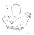
- FIGS 1 and 2 are perspective views of an assembly 1 according to the invention, which comprises a child seat 2 and a chassis 3.
- the child seat 2 comprises a bucket-shaped part 4 and a carrying handle 5, which is connected to the bucket-shaped part 4 on both longitudinal sides thereof.
- Such a child seat is known per se and will not be explained in more detail herein, therefore.
- the child seat 2 further comprises tilting arms 6 disposed on both longitudinal sides of the bucket 4, only one of which is shown in the figures for the sake of clarity.
- the tilting arm that is not shown is provided in mirror image relative to a virtual plane of reflection extending between the two longitudinal sides.
- Each tilting arm 6 is tiltable in a direction opposed to the direction indicated by the arrow P1 about a tilt axis 7 that extends parallel to said longitudinal sides.
- the tilting arm 6 is provided with three cams 8, which are each provided with a sliding surface 9 (see figure 3b ).
- the tilting arm 6 is further provided with a pin 10 extending transversely to the tilt axis 7 and with a signal knob 11 connected thereto, which signal knob extends transversely to the pin 10 and the tilt axis 7.
- the tilting arm 6 is mounted in a recess 13 in the bucket 4 by means of a slide 12.
- the slide 12 comprises two wall portions 14, 15 extending parallel to each other hand as well as a bridge portion 16 connecting said wall portions 14, 15.
- the bridge portion 16 is provided with two recesses 17 at its bottom side, whose function will be explained in more detail yet with reference to figures 3a-5b .
- the slide 12 is further provided with an opening 18 located in the wall portion 14, through which the signal knob 11 is visible in a position in which the child seat is disconnected from or correctly connected to the chassis 3.
- a spring 19 is disposed between the pin 10 and the wall portion 15, which spring exerts a force on the tilting arm 6, as a result of which the tilting arm 6, in a position in which the child seat 2 is not connected to the chassis 3, takes up a position such that the pin 10 extends vertically and the cams 8 take up the position shown in figure 3b .
- An end 20 of a pulling cable 21 is furthermore connected to the pin 10, which pulling cable 21 is connected to an operating element 22 with an end remote from the end 20.
- the operating element 22 is connected to a second pulling cable 21, which is connected to the pin 10 of the other tilting arm 6 with an end remote from the operating element 22.
- the assembly 1 is further provided with the chassis 3, which comprises a plate-shaped part 31.
- the plate-shaped part 31 is provided with three seconds connecting elements 33 on each longitudinal side 32, which connecting elements are spaced apart by a distance such that the second connecting elements 33 can mate with the six cams 8 of the two tilting arms 6.
- Each second connecting element 33 comprises a strip 34 extending transversely to the plate-shaped part 31 and a strip 35 extending along edges of the strip 34.
- the strip 34 and the strip 35 bound a recess 36.
- the recesses 36 of the second connecting elements 33 located on one longitudinal side 32 are oriented in the direction of the recesses 36 of the second connecting elements 33 on the other longitudinal side 32 of the plate-shaped part 31 of the chassis 3.
- the longitudinal sides of the child seat 2 extend substantially parallel to the longitudinal sides 32 of the chassis 3.
- the cams 8 are positioned substantially above the second connecting elements 33. A user will hold the child seat 2 by the carrying handle 5 and subsequently move it downwards in the direction indicated by the arrow P3. During said movement, the openings 17 in the slide 12 of the child seat 2 are moved over the second connecting elements 33.
- the cam 8 is now tilted in the opposite direction of the arrow P1 under the influence of the spring 19, causing the cam 8 to be positioned in the recess 36 of the second connecting element 33 (see figures 5a and 5b ).
- a strong connection between the child seat 2 and the chassis 3 has thus been effected by the cams 8 positioned in the recesses 36.
- the cams 8 are locked against movement in directions parallel to the tilt axes by the strip 35.
- the cams 8 are locked against movement in vertical direction by the plate-shaped part 31 and the strip 35.
- chassis 3 It is also possible to provide the chassis 3 with only four second connecting elements 33, in which case only two connecting elements 33 will be disposed on each longitudinal side 32.
- the child seat 2, which comprises six cams, can also be connected to such a chassis 3.
- Such a chassis 3 is cheaper and more compact than a chassis as shown in figure 1 .
- a chassis comprising a lower number of connecting elements 33 is for example suitable for uses in which comparatively small forces are exerted on the connection between the child seat 2 and the chassis 3, for example when the chassis 3 is used with a stroller.
- chassis 3 When the chassis 3 is used in a base frame for use in a vehicle, in which case comparatively large forces are exerted on the child seat 2 in case of a collision, it is advisable to use a chassis 3 comprising a comparatively large number of second connecting elements 33.
- tilt axis 7 extend transversely to the longitudinal sides.
Landscapes
- Engineering & Computer Science (AREA)
- Transportation (AREA)
- Mechanical Engineering (AREA)
- Chemical & Material Sciences (AREA)
- Combustion & Propulsion (AREA)
- Health & Medical Sciences (AREA)
- Child & Adolescent Psychology (AREA)
- General Health & Medical Sciences (AREA)
- Aviation & Aerospace Engineering (AREA)
- Seats For Vehicles (AREA)
Abstract
An assembly comprises a chassis and a child seat that is detachably connectable to the chassis. The child seat is provided with at least one first connecting element, which is detachably connectable to a second connecting element provided in the chassis. The child seat comprises at least one tilting arm which is tiltable about a tilt axis, which tilting arm is provided with at least two first connecting elements. The chassis is provided with at least one pair of second connecting elements, each comprising a recess on a side facing the tilt axis. Cams can be positioned in the recesses for interconnecting the first and the second connecting elements.
Description
- Assembly comprising a chassis and a child seat being detachably connectable to the chassis, as well as such a child seat and such a chassis.
- The invention relates to an assembly comprising a chassis and a child seat being detachably connectable to the chassis, which child seat is provided with at least one first connecting element, which is detachably connectable to a second connecting element provided in the chassis.
- With such assemblies, which are known per se, a child seat is connected to a chassis, such as a stroller or a base frame present in a vehicle. By connecting the child seat to the chassis, a strong connection with the chassis is realised. Since the child seat can be disconnected from the chassis, the child seat can be easily used as a separate child seat or be connected to another chassis. Thus, a child seat can first be used in combination with a stroller, for example, after which the child seat, connected to a base frame in a vehicle, is used for safely transporting a child in the vehicle.
- The assemblies that have been known so far are comparatively complex in design, and they are comparatively complex to operate.
- The object of the invention is to provide an assembly in which a child seat can be connected to and disconnected from a chassis in a simple manner.
- This object is accomplished with the assembly according to the invention in that the child seat comprises at least one tilting arm which is tiltable about a tilt axis, which tilting arm is provided with at least two first connecting elements, whilst the chassis is provided with at least one pair of second connecting elements, each comprising a recess on a side facing the tilt axis, wherein cams can be positioned in the recesses for interconnecting the first and the second connecting elements.
- A strong connection between the child seat and the chassis is realised by means of the cams positioned in the recesses. By tilting the tilting arm about the tilt axis, all cams connected to the tilting arm are simultaneously moved into or out of the recesses. In this way a simple operation is obtained. Since a number of cams are furthermore connected to a number of recesses, a strong connection is moreover realised.
- One embodiment of the assembly according to the invention is characterised in that the tilting arm can be tilted about the tilt axis against spring force.
- When the child seat is being connected to the chassis and disconnected from the chassis, the tilting arm must be tilted about the tilt axis against spring force. In this way undesirable detachment of the connection between the cams connected to the tilting arm and the recesses is prevented in a simple manner. The connection between the chassis and the child seat can only be broken when a force sufficiently large for tilting the tilting arm about the tilt axis is exerted on the tilting arm.
- Another embodiment of the assembly according to the invention is characterised in that the child seat is provided with at least two tilting arms, whose tilt axes extend substantially parallel to the longitudinal sides of the child seat.
- The tilting arms extending on both longitudinal sides of the child seat provide a strong and stable connection between the child seat and the chassis. When the child seat is used in a vehicle, forces exerted on the child seat in case of a collision of the vehicle will extend substantially parallel to the longitudinal sides, and thus parallel to the tilt axes. Such forces will be taken up by the cams positioned in the recesses when the child seat is connected to the chassis. Since said forces extend in a direction transversely to the direction in which the cams can the risk of the cams undesirably moving out of the recesses is eliminated.
- Yet another embodiment of the assembly according to the invention is characterised in that the tilting arms can be tilted about the tilt axes against spring force by means of a common operating element.
- The connection between the child seat and the chassis can be broken in a simple manner by means of said common operating element.
- Another embodiment of the assembly according to the invention is characterised in that the chassis is provided with at least two pairs of second connecting elements, with the recesses of a first pair of second connecting elements facing towards the recesses of the second pair of second connecting elements.
- When a force extending from the first pair of second connecting elements towards the second pair of connecting elements, or vice versa, is exerted on the child seat, the cams are urged into the second pair of second connecting elements or the first pair of second connecting elements, respectively, so that a strong connection between the child seat and did chassis remains ensured.
- Yet another embodiment of the assembly according to the invention is characterised in that the chassis comprises a plate-shaped part, with which the second connecting elements are connected.
- Such a chassis is simple in design and can be used for various chassis, such as a chassis in a stroller, a base frame in a vehicle, a luggage carrier of a bicycle, etc. This makes it attractive for a user to buy various chassis for various uses, to which the child seat can then be connected. Several chassis that are known per se are provided with comparatively complex operating elements, so that the chassis are relatively expensive, which makes it unattractive to buy a number of chassis for different uses.
- Yet another embodiment of the assembly according to the invention is characterised in that each cam comprises a sliding surface including an acute angle with the second connecting element, which sliding surface can slide along the second connecting element when the first connecting element is being connected to the second connecting element, as a result of which the tilting arm can be tilted to a position in which the sliding surface extends substantially parallel to the second connecting element, after which the tilting arm can be tilted in an opposite direction for positioning the cam in the recess of the second connecting element.
- The sliding surface makes it possible to realise a connection between the cam and the recess in a simple manner.
- The invention will now be explained in more detail with reference to the drawings, in which:
-
Figure 1 is a perspective, exploded view of an assembly according to the invention; -
Figure 2 is a perspective view of the assembly offigure 1 in the assembled condition thereof; -
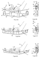
Figures 3a and 3b are a perspective view and a cross-sectional view, respectively, of a child seat disconnected from the chassis; -
Figures 4a and 4b are a perspective view and a cross-sectional view, respectively, of the child seat and the chassis being disconnected from each other, in which the tilting arm is tilted about the tilt axis; -
Figures 5a and 5b are a perspective view and a cross-sectional view, respectively, of a child seat connected to the chassis. - Like parts are indicated by the same numerals in the figures.
-
Figures 1 and2 are perspective views of anassembly 1 according to the invention, which comprises achild seat 2 and achassis 3. Thechild seat 2 comprises a bucket-shaped part 4 and acarrying handle 5, which is connected to the bucket-shaped part 4 on both longitudinal sides thereof. Such a child seat is known per se and will not be explained in more detail herein, therefore. - The
child seat 2 further comprises tiltingarms 6 disposed on both longitudinal sides of thebucket 4, only one of which is shown in the figures for the sake of clarity. The tilting arm that is not shown is provided in mirror image relative to a virtual plane of reflection extending between the two longitudinal sides. - Each
tilting arm 6 is tiltable in a direction opposed to the direction indicated by the arrow P1 about atilt axis 7 that extends parallel to said longitudinal sides. Thetilting arm 6 is provided with threecams 8, which are each provided with a sliding surface 9 (seefigure 3b ). Thetilting arm 6 is further provided with apin 10 extending transversely to thetilt axis 7 and with asignal knob 11 connected thereto, which signal knob extends transversely to thepin 10 and thetilt axis 7. The tiltingarm 6 is mounted in arecess 13 in thebucket 4 by means of aslide 12. Theslide 12 comprises twowall portions bridge portion 16 connectingsaid wall portions bridge portion 16 is provided with tworecesses 17 at its bottom side, whose function will be explained in more detail yet with reference tofigures 3a-5b . Theslide 12 is further provided with anopening 18 located in thewall portion 14, through which thesignal knob 11 is visible in a position in which the child seat is disconnected from or correctly connected to thechassis 3. Aspring 19 is disposed between thepin 10 and thewall portion 15, which spring exerts a force on thetilting arm 6, as a result of which the tiltingarm 6, in a position in which thechild seat 2 is not connected to thechassis 3, takes up a position such that thepin 10 extends vertically and thecams 8 take up the position shown infigure 3b . - An
end 20 of apulling cable 21 is furthermore connected to thepin 10, which pullingcable 21 is connected to anoperating element 22 with an end remote from theend 20. Theoperating element 22 is connected to asecond pulling cable 21, which is connected to thepin 10 of theother tilting arm 6 with an end remote from theoperating element 22. By pivoting theoperating element 22 in the direction indicated by the arrow P2 (seefigure 2 ), the tiltingarms 6 are tilted in the direction indicated by the arrow P1 about the tilt axes 7 (seefigure 4B ) against the spring force of thesprings 19. When theoperating element 22 is released by a user, thesprings 19 will exert forces or on the tiltingarms 6, as a result of which the tiltingarms 6 will be tilted in the opposite direction of the arrow P1 about thetilt axes 7. - The
assembly 1 is further provided with thechassis 3, which comprises a plate-shaped part 31. The plate-shaped part 31 is provided with threeseconds connecting elements 33 on eachlongitudinal side 32, which connecting elements are spaced apart by a distance such that the second connectingelements 33 can mate with the sixcams 8 of the two tiltingarms 6. Each second connectingelement 33 comprises astrip 34 extending transversely to the plate-shaped part 31 and astrip 35 extending along edges of thestrip 34. Thestrip 34 and thestrip 35 bound arecess 36. Therecesses 36 of the second connectingelements 33 located on onelongitudinal side 32 are oriented in the direction of therecesses 36 of the second connectingelements 33 on the otherlongitudinal side 32 of the plate-shaped part 31 of thechassis 3. - The manner of connecting the
child seat 2 according to the invention to thechassis 3 according to the invention will now be explained in more detail with reference tofigures 3a-5b . - In the relative positions of the
child seat 2 and thechassis 3 shown infigures 3a and 3b , the longitudinal sides of thechild seat 2 extend substantially parallel to thelongitudinal sides 32 of thechassis 3. Thecams 8 are positioned substantially above the second connectingelements 33. A user will hold thechild seat 2 by thecarrying handle 5 and subsequently move it downwards in the direction indicated by the arrow P3. During said movement, theopenings 17 in theslide 12 of thechild seat 2 are moved over the second connectingelements 33. Upon further movement of thechild seat 2 in the direction indicated by the arrow P3, the slidingsurface 9 of thecam 8 will make contact with a side of thestrip 35 remote from thestrip 34, as a result of which thecam 8 will be pivoted in the direction indicated by the arrow P1 about thetilt axis 7 against the spring force of thespring 19, until the slidingsurface 9 extends substantially parallel to thestrip 34 and can be moved down past the strip 35 (seefigures 4a and 4b ). Thechild seat 2 is moved in the direction indicated by the arrow P3 until the slidingsurface 9 is located under thestrip 35. Thecam 8 is now tilted in the opposite direction of the arrow P1 under the influence of thespring 19, causing thecam 8 to be positioned in therecess 36 of the second connecting element 33 (seefigures 5a and 5b ). A strong connection between thechild seat 2 and thechassis 3 has thus been effected by thecams 8 positioned in therecesses 36. Thecams 8 are locked against movement in directions parallel to the tilt axes by thestrip 35. Thecams 8 are locked against movement in vertical direction by the plate-shapedpart 31 and thestrip 35. Once thecams 8 have taken up the position shown infigure 5b , thesignal knob 11 will be visible through theopening 18, providing an extra indication to a user that thechild seat 2 is directly connected to thechassis 3. - To disconnect the child seat from the
chassis 3, a user will pivot the operatingelement 22 in the direction indicated by the arrow P2, as a result of which the tiltingarms 6, and thus thecams 8, will be pivoted in the direction indicated by the arrow P1 to the position shown infigure 4b . The user can now lift thechild seat 2 from thechassis 3 in the opposite direction of the arrow P3. - It is also possible to provide the
chassis 3 with only four second connectingelements 33, in which case only two connectingelements 33 will be disposed on eachlongitudinal side 32. Thechild seat 2, which comprises six cams, can also be connected to such achassis 3. Such achassis 3 is cheaper and more compact than a chassis as shown infigure 1 . A chassis comprising a lower number of connectingelements 33 is for example suitable for uses in which comparatively small forces are exerted on the connection between thechild seat 2 and thechassis 3, for example when thechassis 3 is used with a stroller. When thechassis 3 is used in a base frame for use in a vehicle, in which case comparatively large forces are exerted on thechild seat 2 in case of a collision, it is advisable to use achassis 3 comprising a comparatively large number of second connectingelements 33. - It is also possible to have the
tilt axis 7 extend transversely to the longitudinal sides. - It is also possible for the
recesses 36 of the second connectingelements 33 to extend away from each other, in which case thecams 8 of the tiltingarms 6 must be oriented towards each other.
Claims (9)
- An assembly comprising a chassis and a child seat that is detachably connectable to the chassis, which child seat is provided with at least one first connecting element, which is detachably connectable to a second connecting element provided in the chassis, characterised in that the child seat comprises at least one tilting arm which is tiltable about a tilt axis, which tilting arm is provided with at least two first connecting elements, whilst the chassis is provided with at least one pair of second connecting elements, each comprising a recess on a side facing the tilt axis, wherein cams can be positioned in the recesses for interconnecting the first and the second connecting elements.
- An assembly according to claim 1, characterised in that the tilting arm can be tilted about the tilt axis against spring force.
- An assembly according to claim 1 or 2, characterised in that the child seat is provided with at least two tilting arms, whose tilt axes extend substantially parallel to the longitudinal sides of the child seat.
- An assembly according to claim 3, characterised in that the tilting arms can be tilted about the tilt axes against spring force by means of a common operating element.
- An assembly according to claim 3 or 4, characterised in that the chassis is provided with at least two pairs of second connecting elements, with the recesses of a first pair of second connecting elements facing towards the recesses of the second pair of second connecting elements.
- An assembly according to any one of the preceding claims, characterised in that the chassis comprises a plate-shaped part, with which the second connecting elements are connected.
- An assembly according to any one of the preceding claims, characterised in that each cam comprises a sliding surface including an acute angle with the second connecting element, which sliding surface can slide along the second connecting element when the first connecting element is being connected to the second connecting element, as a result of which the tilting arm can be tilted to a position in which the sliding surface extends substantially parallel to the second connecting element, after which the tilting arm can be tilted in an opposite direction for positioning the cam in the recess of the second connecting element.
- A child seat suitable for an assembly according to any one of the preceding claims, which child seat comprises at least one tilting arm which is tiltable about a tilt axis, which tilting arm is provided with at least two first connecting elements.
- A chassis suitable for an assembly according to any one of the preceding claims 1-7, characterised in that said chassis is provided with at least one pair of connecting elements, which each comprise a recess.
Applications Claiming Priority (1)
| Application Number | Priority Date | Filing Date | Title |
|---|---|---|---|
| NL1035276A NL1035276C2 (en) | 2008-04-09 | 2008-04-09 | Assembly provided with an undercarriage and a child's seat that can be detachably connected to the undercarriage, as well as such a child's seat and such an undercarriage. |
Publications (1)
| Publication Number | Publication Date |
|---|---|
| EP2108540A1 true EP2108540A1 (en) | 2009-10-14 |
Family
ID=40280723
Family Applications (1)
| Application Number | Title | Priority Date | Filing Date |
|---|---|---|---|
| EP09004951A Withdrawn EP2108540A1 (en) | 2008-04-09 | 2009-04-03 | Child seat |
Country Status (3)
| Country | Link |
|---|---|
| US (1) | US20090256406A1 (en) |
| EP (1) | EP2108540A1 (en) |
| NL (1) | NL1035276C2 (en) |
Families Citing this family (10)
| Publication number | Priority date | Publication date | Assignee | Title |
|---|---|---|---|---|
| US8197005B2 (en) | 2008-09-03 | 2012-06-12 | Thorley Industries Llc | Infant care apparatus |
| US10220734B2 (en) | 2013-03-05 | 2019-03-05 | Pidyon Controls Inc. | Car seat |
| CN203996350U (en) | 2014-01-10 | 2014-12-10 | 克斯克管理公司 | Foldable go-cart |
| TWI624386B (en) * | 2014-12-23 | 2018-05-21 | 明門香港股份有限公司 | Child safety seat |
| MX2017013976A (en) * | 2015-05-12 | 2018-03-14 | Pidyon Controls Inc | Car seat and connection system. |
| US10548399B2 (en) * | 2016-09-14 | 2020-02-04 | Cabela's Llc | Reclining collapsible chair |
| US11944212B2 (en) * | 2019-09-19 | 2024-04-02 | Thorley Industries, Llc | Infant care apparatus |
| US11102954B2 (en) * | 2019-11-15 | 2021-08-31 | Chris Jensen | Bicycle-mounted platform and brace for pet transport |
| TW202231521A (en) * | 2020-12-21 | 2022-08-16 | 瑞士商明門瑞士股份有限公司 | Travel system having a child carrier with handle that extends and/or rotates |
| US20240166101A1 (en) * | 2022-11-21 | 2024-05-23 | Dorel Juvenile Group, Inc. | Child restraint |
Citations (4)
| Publication number | Priority date | Publication date | Assignee | Title |
|---|---|---|---|---|
| GB2240035A (en) * | 1989-12-21 | 1991-07-24 | Combi Co | Auxiliary chair for vehicle |
| GB2247614A (en) * | 1990-09-04 | 1992-03-11 | Gerry Baby Prod | Infant seat apparatus |
| US5794951A (en) * | 1996-10-25 | 1998-08-18 | Century Products Company | Child's stroller with manually operable accessory latch assembly |
| EP0901953A2 (en) * | 1997-09-10 | 1999-03-17 | Graco Children's Products Inc. | Infant carrier mounting system |
Family Cites Families (5)
| Publication number | Priority date | Publication date | Assignee | Title |
|---|---|---|---|---|
| US5772279A (en) * | 1995-08-31 | 1998-06-30 | Kolcraft Enterprises, Inc. | Coupling system for infant carrier to second support device |
| US5947555A (en) * | 1996-11-22 | 1999-09-07 | Kolcraft Enterprises, Inc. | Infant seat and stroller coupling system |
| US20030102702A1 (en) * | 2001-08-13 | 2003-06-05 | Rick Daley | Booster seat |
| US6715828B1 (en) * | 2002-10-07 | 2004-04-06 | Kenny Cheng | Infant carrier |
| TW200533536A (en) * | 2004-02-19 | 2005-10-16 | Combi Corp | Locking mechanism of child car seat and child car seat securing apparatus of stroller |
-
2008
- 2008-04-09 NL NL1035276A patent/NL1035276C2/en not_active IP Right Cessation
-
2009
- 2009-04-03 EP EP09004951A patent/EP2108540A1/en not_active Withdrawn
- 2009-04-08 US US12/420,543 patent/US20090256406A1/en not_active Abandoned
Patent Citations (4)
| Publication number | Priority date | Publication date | Assignee | Title |
|---|---|---|---|---|
| GB2240035A (en) * | 1989-12-21 | 1991-07-24 | Combi Co | Auxiliary chair for vehicle |
| GB2247614A (en) * | 1990-09-04 | 1992-03-11 | Gerry Baby Prod | Infant seat apparatus |
| US5794951A (en) * | 1996-10-25 | 1998-08-18 | Century Products Company | Child's stroller with manually operable accessory latch assembly |
| EP0901953A2 (en) * | 1997-09-10 | 1999-03-17 | Graco Children's Products Inc. | Infant carrier mounting system |
Also Published As
| Publication number | Publication date |
|---|---|
| NL1035276C2 (en) | 2009-10-12 |
| US20090256406A1 (en) | 2009-10-15 |
Similar Documents
| Publication | Publication Date | Title |
|---|---|---|
| US20090256406A1 (en) | Assembly Comprising a Chassis and a Child Seat Being Detachably Connectable to the Chassis, As Well As Such a Child Seat and Such a Chassis | |
| US8328208B2 (en) | Stroller connectable with a car seat | |
| US11472316B2 (en) | Coupling mechanism as well as a child seat transporting system provided with at least one such coupling mechanism | |
| US6722690B2 (en) | Foldable strolier | |
| EP3025927B1 (en) | Folding travel stroller latch and wheel positioning mechanism | |
| EP1331712B1 (en) | Electrical device for mounting on a top-hat rail | |
| US6702685B2 (en) | Collapsible swing and method of using the same | |
| US20120056393A1 (en) | Stroller | |
| FR2827555A1 (en) | Seat track assembly for vehicle, has connector pivotally connected to second seat track and handle to engages with multiple pins and move each pin from engaged to disengaged position | |
| EP3335963B1 (en) | Expandable child carrier | |
| CN211032283U (en) | Vehicle with a steering wheel | |
| EP1356986B1 (en) | Child safety seat | |
| CA2980130A1 (en) | Stroller tray or bumper bar with movement in two axes | |
| JP6107722B2 (en) | Vehicle seat table | |
| US20070080567A1 (en) | Child seat | |
| JP5798890B2 (en) | Braking mechanism for baby stroller, wheel holding mechanism for baby stroller, and baby stroller | |
| EP1927503B1 (en) | Child vehicle seat | |
| CA2502936C (en) | Device for lock-fixing an apparatus designed to be mounted in a rack | |
| FR2772319A1 (en) | Vehicle seat, folds flat to vehicle floor, | |
| EP1473187A1 (en) | Seat for transport vehicles, especially air transport | |
| EP0844134B1 (en) | Actuating device for a controlling member of a vehicle seat mechanism and seat provided with such a device | |
| EP1369296A1 (en) | Infant seat | |
| US6719575B2 (en) | Lever-type connector | |
| EP0373081A1 (en) | Collapsible seat especially for the equipment of automotive vehicles | |
| EP2183176B1 (en) | Dock shelter |
Legal Events
| Date | Code | Title | Description |
|---|---|---|---|
| PUAI | Public reference made under article 153(3) epc to a published international application that has entered the european phase |
Free format text: ORIGINAL CODE: 0009012 |
|
| AK | Designated contracting states |
Kind code of ref document: A1 Designated state(s): AT BE BG CH CY CZ DE DK EE ES FI FR GB GR HR HU IE IS IT LI LT LU LV MC MK MT NL NO PL PT RO SE SI SK TR |
|
| 17P | Request for examination filed |
Effective date: 20100406 |
|
| 17Q | First examination report despatched |
Effective date: 20100510 |
|
| STAA | Information on the status of an ep patent application or granted ep patent |
Free format text: STATUS: EXAMINATION IS IN PROGRESS |
|
| STAA | Information on the status of an ep patent application or granted ep patent |
Free format text: STATUS: THE APPLICATION IS DEEMED TO BE WITHDRAWN |
|
| 18D | Application deemed to be withdrawn |
Effective date: 20171103 |