EP2108162B1 - Study navigation system and method. - Google Patents
Study navigation system and method. Download PDFInfo
- Publication number
- EP2108162B1 EP2108162B1 EP07847157.0A EP07847157A EP2108162B1 EP 2108162 B1 EP2108162 B1 EP 2108162B1 EP 07847157 A EP07847157 A EP 07847157A EP 2108162 B1 EP2108162 B1 EP 2108162B1
- Authority
- EP
- European Patent Office
- Prior art keywords
- image
- series
- images
- subseries
- image series
- Prior art date
- Legal status (The legal status is an assumption and is not a legal conclusion. Google has not performed a legal analysis and makes no representation as to the accuracy of the status listed.)
- Active
Links
Images




Classifications
-
- G—PHYSICS
- G06—COMPUTING OR CALCULATING; COUNTING
- G06T—IMAGE DATA PROCESSING OR GENERATION, IN GENERAL
- G06T12/00—Tomographic reconstruction from projections
- G06T12/30—Image post-processing, e.g. metal artefact correction
-
- G—PHYSICS
- G16—INFORMATION AND COMMUNICATION TECHNOLOGY [ICT] SPECIALLY ADAPTED FOR SPECIFIC APPLICATION FIELDS
- G16H—HEALTHCARE INFORMATICS, i.e. INFORMATION AND COMMUNICATION TECHNOLOGY [ICT] SPECIALLY ADAPTED FOR THE HANDLING OR PROCESSING OF MEDICAL OR HEALTHCARE DATA
- G16H30/00—ICT specially adapted for the handling or processing of medical images
- G16H30/20—ICT specially adapted for the handling or processing of medical images for handling medical images, e.g. DICOM, HL7 or PACS
Definitions
- the selective representative image series 50a is preferably large enough to avoid missing features of interest.
- the minimum size of a feature of interest is partially dictated by the specific application, that is, the reason behind user 11 's examination of the image data.
- the underlying image data comprises a series of planar images. Each image represents a substantially parallel cross sectional image of a scanned portion of a patient. Thus, each image is spaced from an adjacent image by a given distance.
- the selective representative image series 50a is made up of only selected images from the full image series 30 , the distance between two images in selective representative image series 50a will generally be larger than in full image series 30 .
- the representative images should be chosen such that the spacing between them is not greater than the minimum size of those features.
- one of the subseries 52 will have less then 10 images or a different number other than 10 can be chosen such that the number of images in full image series 30 is either divisible by that number or is closer to being divisible by that number than by 10.
- merged representative image series 50b will generally provide image data from more than one image of each subseries.
- each image of merged representative image series 50b may display features from each of the planes of the images in each subseries.
- the images that make up merged representative image series 50b are projection images. Projections images are images that display features that are not necessarily coplanar.
- each merged image may look similar to an x-ray image, which displays features that exist in more than one plane. This is in contrast to planar cross-sectional images such as those that generally make up full image series 30 .
- representative image series 50 is generally made small enough in comparison to full image series 30 so that it would save a medical practitioner time to examine the representative image series 50 in place of full image series 30 .
- a representative image series that is virtually the same size as the original full image series 30 would not generally save a medical practitioner time.
- each representative image is selected from a subseries of images.
- selective representative image series 50a is not made so small that a significant amount of detail is skipped over between each representative image.
- the size of the series impacts on how much time can be saved for user 11 . If the representative image series 50 is too large, user 11 may not save much time given that he or she has to look through a large number of images. If the representative image series 50 series is too small, user may not save much time given that he or she may not be able to rely on the representative images to provide the appropriate level of detail and may therefore need to constantly go back and examine the subseries that make up each representative image of representative image series 50 .
- the method starts at step ( 402 ) and is initiated when user 11 first launches a full image series 30 .
- image processing module 12 causes display driver 22 to display the representative image series 50 on diagnostic interface 23 .
- image representative series generation module 16 determines an appropriate selective representative image series size.
- the selective representative image series size denotes the number of images in the selective representative image series 50a .
- the selective representative image series size is chosen to be substantially smaller than the size of full image series 30.
- the actual selective representative image series size can be chosen by user 11 or can be a system default setting, either of which may be stored on user preference database 24 .
- the selective representative image series size may be chosen to be one tenth the size of the full image series 30 .
- step ( 612 ) the representative series generation module 16 determines whether user 11 has chosen to view a subseries 52a associated with particular image of representative image series 50a in greater detail. If the user has chosen to view a particular subseries 52a in greater detail then step ( 614 ) is executed. If not, then step ( 610 ) is repeated.
- image combining module 18 causes each of the combined images that make up merged representative image series 50b to be stored.
- the merged representative image series 50b is only temporarily stored until it is transmitted to main navigational system 10 . Once merged representative image series 50b has been transmitted, then it is deleted from the image server. In other embodiments merged representative image series 50b is optionally stored for use in subsequent sessions.
- study navigation system 5 could also be adapted to any other type of image or document display system. While the above description provides examples of the embodiments, it will be appreciated that some features and/or functions of the described embodiments are susceptible to modification without departing from the spirit and principles of operation of the described embodiments. Accordingly, what has been described above has been intended to be illustrative of the invention and nonlimiting and it will be understood by persons skilled in the art that other variants and modifications may be made without departing from the scope of the invention as defined in the claims appended hereto.
Landscapes
- Engineering & Computer Science (AREA)
- Health & Medical Sciences (AREA)
- Radiology & Medical Imaging (AREA)
- Theoretical Computer Science (AREA)
- General Physics & Mathematics (AREA)
- Nuclear Medicine, Radiotherapy & Molecular Imaging (AREA)
- Physics & Mathematics (AREA)
- Epidemiology (AREA)
- General Health & Medical Sciences (AREA)
- Medical Informatics (AREA)
- Primary Health Care (AREA)
- Public Health (AREA)
- Processing Or Creating Images (AREA)
- Measuring And Recording Apparatus For Diagnosis (AREA)
- Navigation (AREA)
Description
- The present invention relates to image viewing and navigation systems and methods and more particularly to a system and method for navigating and viewing planar images.
- Commercially available image viewing systems in the medical field utilize various techniques to present visual representations of image data to a user. Specifically, image data produced within modalities such as Computed Tomography (CT) and the like is displayed on a display terminal for review by a medical practitioner at a medical treatment site. Typically, the image data produced by the modalities is in a form of a series of planar images that are aligned along an axis that is normal to the plane of each image.
- By viewing the various planar images that make up the image series, a medical practitioner can better determine the presence or absence of a medical condition (e.g. disease, tissue damage etc.). Many attempts to optimize the display and presentation of the planar image data for viewing by a medical practitioner have been made. Currently, when a medical professional wishes to review an image series that covers an area of interest, he or she must either view each image individually, or choose to skip certain images. This process can be both inefficient and prone to error. It is possible that skipping certain images in a non-systematic manner may cause the medical professional to overlook the presence of a medical condition that is reflected in one of the skipped images. For reasons such as these, it is often very difficult and time consuming for medical practitioners to review large amounts of image data.
-
US 6 988 244 discloses a method for navigating an image series containing a number of aligned planar images the method comprising: - (a) grouping the images of the image series into a number of subseries, the number of subseries being less than the first number of images;
- (b) generating a representative image series by generating an image from each subseries;
- (c) displaying the representative image series;
- (d) determining whether an image from the representative image series has been selected; and,
- (e) if an image from the representative image series has been selected, then displaying the subseries associated with the selected image, and
- (e) determining whether to end the display of the subseries and if it has been determined to end the display of the subseries, then performing (c).
- Also
US 2006/033728 andUS 2005/259116 disclose such methods. - It is an object of this invention to enhance the prior art viewing and navigation systems.
- The above mentioned objects are realised by a method of navigating an image series having the specific features defined in claim 1. Specific features for preferred embodiments of the invention are set out in the dependent claims.
- The advantages and embodiments of the present invention will become apparent from the following description and drawings.
- For a better understanding of the embodiments described herein and to show more clearly how they may be carried into effect, reference will now be made, by way of example only, to the accompanying drawings which show at least one exemplary embodiment, and in which:
-
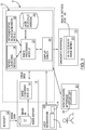
FIG. 1 is a block diagram of an exemplary embodiment of a study navigation system; -
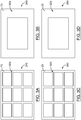
FIGS. 2A and 2B are schematic diagrams illustrating two exemplary view configurations for a selective representative image series; -
FIGS. 2C and 2D are schematic diagrams illustrating two exemplary view configurations for a subseries associated with the selective representative image series ofFIGS. 2A and 2B ; -
FIGS. 3A and 3B are schematic diagrams illustrating two exemplary view configurations for a merged representative image series; -
FIGS. 3C and 3D are schematic diagrams illustrating two exemplary view configurations for a subseries associated with the selective representative image series ofFIGS. 3A and 3B ; -
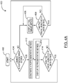
FIG. 4A is a flowchart diagram of the main operational steps executed by the study navigation system ofFIG. 1 according to various embodiments; -
FIG. 4B is a flowchart diagram of the main operational steps executed by the study navigation system ofFIG. 1 when image data is received from a modality; -
FIG. 4C is a flowchart diagram of the main operational steps executed by the study navigation system ofFIG. 1 according to various embodiments; -
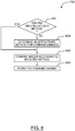
FIG. 5 is a flowchart diagram of the main operational steps executed by the representative series generation module ofFIG. 1 when generating and displaying a representative image series; -
FIG. 6 is a flowchart diagram of an example set of operational steps executed by the study navigation system ofFIG. 1 when generating and displaying a selective representative image series; -
FIG. 7 is a flowchart diagram of an example set of operational steps executed by the study navigation system ofFIG. 1 when generating and displaying a merged representative image series; -
FIG. 8 is a flowchart diagram of an example set of operational steps executed by the study navigation system ofFIG. 1 when combining images; and, -
FIG. 9 is a schematic diagram showing the relationship between a full image series and a merged representative image series. - It will be appreciated that for simplicity and clarity of illustration, elements shown in the figures have not necessarily been drawn to scale. For example, the dimensions of some of the elements may be exaggerated relative to other elements for clarity.
- It will be appreciated that for simplicity and clarity of illustration, where considered appropriate, reference numerals may be repeated among the figures to indicate corresponding or analogous elements or steps. In addition, numerous specific details are set forth in order to provide a thorough understanding of the exemplary embodiments described herein. However, it will be understood by those of ordinary skill in the art that the embodiments described herein may be practiced without these specific details. In other instances, well-known methods, procedures and components have not been described in detail so as not to obscure the embodiments described herein. Furthermore, this description is not to be considered as limiting the scope of the embodiments described herein in any way, but rather as merely describing the implementation of the various embodiments described herein.
- The embodiments of the systems and methods described herein may be implemented in hardware or software, or a combination of both. However, preferably, these embodiments are implemented in computer programs executing on programmable computers each comprising at least one processor, a data storage system (including volatile and non-volatile memory and/or storage elements), at least one input device, and at least one output device. For example and without limitation, the programmable computers may be a mainframe computer, server, personal computer, laptop, personal data assistant, or cellular telephone. Program code is applied to input data to perform the functions described herein and generate output information. The output information is applied to one or more output devices, in known fashion.
- Each program is preferably implemented in a high level procedural or object oriented programming and/or scripting language to communicate with a computer system. However, the programs can be implemented in assembly or machine language, if desired. In any case, the language may be a compiled or interpreted language. Each such computer program is preferably stored on a storage media or a device (e.g. ROM or magnetic diskette) readable by a general or special purpose programmable computer, for configuring and operating the computer when the storage media or device is read by the computer to perform the procedures described herein. The inventive system may also be considered to be implemented as a computer-readable storage medium, configured with a computer program, where the storage medium so configured causes a computer to operate in a specific and predefined manner to perform the functions described herein.
- Furthermore, the system, processes and methods of the described embodiments are capable of being distributed in a computer program product comprising a computer readable medium that bears computer usable instructions for one or more processors. The medium may be provided in various forms, including one or more diskettes, compact disks, tapes, chips, wireline transmissions, satellite transmissions, internet transmission or downloadings, magnetic and electronic storage media, digital and analog signals, and the like. The computer useable instructions may also be in various forms, including compiled and non-compiled code.
-
FIG. 1 illustrates the basic elements of an exemplary embodiment of astudy navigation system 5. Specifically,study navigation system 5 includes a mainnavigational system 10 andimage combining module 18. In some embodiments, mainnavigational system 10 includesimage combining module 18. Mainnavigational system 10 includes animage processing module 12, aseries launching module 14, a representativeseries generation module 16, and adisplay driver 22. Thus, in various embodiments the mainnavigational system 10 is simply the study navigation system excluding theimage combining module 18. As will be explained below some embodiments ofstudy navigation system 5 separate theimage combining module 18 in order to reduce the amount of data traffic flowing betweenimage server 15. - As discussed in more detail above, it should be understood that
study navigation system 5 may be implemented in hardware or software or a combination of both. Specifically, the modules ofstudy navigation system 5 are preferably implemented in computer programs executing on programmable computers each comprising at least one processor, a data storage system and at least one input and at least one output device. Without limitation the programmable computers may be a mainframe computer, server, personal computer, laptop, personal data assistant or cellular telephone. In some embodiments, the modules ofstudy navigation system 5 are implemented in software and installed on the hard drive ofuser workstation 19 and onimage server 15, such thatuser workstation 19 interoperates withimage server 15 in a client-server configuration. In other embodiments, the modules ofstudy navigation system 5 can run from a single dedicated workstation that may be associated directly with aparticular modality 13. In yet other embodiments, thestudy navigation system 5 can be configured to run remotely on theuser workstation 19 while communication with theimage server 15 occurs via a wide area network (WAN), such as through the Internet. - As shown, image data associated with a full image series 30 (i.e. a series of medical exam images) is generated by a
modality 13 and stored in animage database 17 on animage server 15.Full image series 30 may be retrieved fromimage database 17 onimage server 15 and displayed ondiagnostic interface 23. Alternatively, arepresentative image series 50 may be retrieved and displayed in place offull image series 30.User 11 may review either of the above-mentioned series for a variety of reasons, including but not limited to a search for a specific pathology. - In various embodiments,
user 11 is able to choose between viewing arepresentative image series 50 or the completefull image series 30 by entering appropriate commands as will be described below. In some embodiments,representative image series 50 is used as a shorter proxy for thefull image series 30. Thus,representative image series 50 generally has fewer images thanfull image series 30. The use of a shorter series may allowuser 11 to spend less time in reviewing the images, in order to for example determine if there is evidence of some sort of pathology. Thus,representative image series 50 allows for an alternative manner of navigating through the image data that may be more efficient as compared to simply viewing the various images offull image series 30. - In addition, in some embodiments, there is more than one type of
representative image series 50. In such embodiments, certain types ofrepresentative image series 50 maybe created onimage server 15 and not on mainnavigational system 10. Therefore, the use of a smaller representative image series rather than the largerfull image series 30 means that less data must be transferred fromimage server 15 to mainnavigational system 10. - In various embodiments,
representative image series 50 can be of at least two types. The first type is the selectiverepresentative image series 50a and the second type is the mergedrepresentative image series 50b. The termrepresentative image series 50 will continue to be used to refer to both selectiverepresentative image series 50a and mergedrepresentative image series 50b when it is not necessary to differentiate between the two or to refer to either in particular. It should be understood that although only two types of representative image series are described it is not intended to exclude the use of other types ofrepresentative image series 50. The selectiverepresentative image series 50a is made up of selected images fromfull image series 30. In some embodiments, selectiverepresentative image series 50a is chosen to have approximately 1/n the number of images asfull image series 30. In various embodiments the images in selectiverepresentative image series 50a are chosen from approximately evenly spaced intervals infull image series 30. In such embodiments, each of the images may be chosen as every nth image infull image series 30. - In various embodiments, the use of selective
representative image series 50a allowsuser 11 to view 1/n the number of images and thereby potentially save time and increase efficiency. In some embodiments, the size of selectiverepresentative image series 50a denotes the number of images in selective representative image series. Thus, the larger the number n is, the less images are present and the smaller the size of the selective image series. As will be discussed below, the size of the selectiverepresentative image series 50a is chosen in consideration of a number of factors. For example, the selectiverepresentative image series 50a is preferably small enough so as to create a navigational system for the image data that can be navigated in a relatively short time. - A second consideration is that the selective
representative image series 50a is preferably large enough to avoid missing features of interest. The minimum size of a feature of interest is partially dictated by the specific application, that is, the reason behinduser 11's examination of the image data. As was explained above, the underlying image data comprises a series of planar images. Each image represents a substantially parallel cross sectional image of a scanned portion of a patient. Thus, each image is spaced from an adjacent image by a given distance. Given that the selectiverepresentative image series 50a is made up of only selected images from thefull image series 30, the distance between two images in selectiverepresentative image series 50a will generally be larger than infull image series 30. Thus, ifuser 11 is interested in a specific pathology that may be manifested in features having a given minimum size, then the representative images should be chosen such that the spacing between them is not greater than the minimum size of those features. - One way of achieving this is to ensure that selective
representative image series 50a is large enough such that it includes a sufficient number of images fromfull image series 30 so that the spacing between any two images is smaller than the minimum size of a feature of interest. For example, ifuser 11 would like to make sure that he or she does not overlook a blood vessel aneurysm then the spacing between images should not be made larger than the smallest expected size of the aneurysm. - Merged
representative image series 50b is made up of merged images fromfull image series 30. In various embodiments, the merged images are created by merging consecutive images offull image series 30. In some embodiments, each merged image of the mergedrepresentative image series 50b is generated by merging approximately the same number of images. Thus, in such embodiments, mergedrepresentative image series 50b can be chosen to have 1/n the number of images asfull image series 30 by merging every n images offull image series 30 into one merged image. It is not necessary that every merged image be formed from the same number of merged images. For example, the total number of images may not be divisible by the number n and therefore at least one of the merged images may be composed of fewer images than the other merged images that make up mergedrepresentative image series 50b. - It is not intended to exclude the possibility of a
representative image series 50 that is formed by merging non-consecutive images of afull images series 30. For example, but not limited to, it may be the case that a particularfull image series 30 may be particularly dense and therefore therepresentative image series 50 may be formed by merging images spaced k images apart rather than consecutive images, where k is greater than 1. Alternatively, the images could be chosen such that they are not spaced by the same interval. Yet another alternative is to formrepresentative image series 50 by generating an image from each subseries 52 by combining a portion of each image in the subseries 52. This could for example, but not limited to, be accomplished by ignoring certain features (or portions) during the merging process. An example of such features (or portions) could be all features (or portions) in the images having an intensity above or below a certain threshold. Alternatively, the portions or images could be selected based on their location within the image. Any appropriate method of choosing portions of the images can be utilized. As another alternative, arepresentative image series 50 may be formed by combining portions of only selected images in each subseries 52. - In various embodiments, the use of merged
representative image series 50b allowsuser 11 to view less images than he or she would otherwise when viewingfull image series 30. As mentioned above, in some embodiments mergedrepresentative image series 50b may comprise 1/n the number of images offull image series 30. Assuming then number of images infull image series 30 is divisible by n, this may be accomplished by merging every n images offull image series 30 into one image. - In various embodiments, each
representative image series representative image series 50a, the subseries 52a is the portion of the overallfull image series 30 from which the representative image is chosen. For example, if selectiverepresentative image series 50a is formed by taking every tenth image offull image series 30 then each subseries would be composed of a set of 10 consecutive images offull image series 30, assuming that the number of images infull image series 30 is divisible by 10. If the number of images is not divisible by 10 then optionally one of the subseries 52 will have less then 10 images. Alternatively, a different number other than 10 can be chosen such that the number of images infull image series 30 is either divisible by that number or is closer to being divisible by that number than by 10. - In the case of the merged
representative image series 50b, the subseries 52b is the portion of the overallfull image series 30 that is merged in order to create the merged image of mergedrepresentative image series 50b. For example, if mergedrepresentative image series 50b is formed by merging every ten consecutive images offull image series 30 into a single image, then each subseries 52 would be composed of a set of 10 consecutive images offull image series 30, assuming that the number of images infull image series 30 is divisible by 10. As explained above, if the number of images is not divisible by 10 then optionally one of the subseries 52 will have less then 10 images or a different number other than 10 can be chosen such that the number of images infull image series 30 is either divisible by that number or is closer to being divisible by that number than by 10. -
Representative image series full image series 30. For example, in various embodiments, selectiverepresentative image series 50a consists of only a single image from each subseries. Thus, in terms of the total image information contained in the subseries, only the information present in the selected image is transferred to selectiverepresentative image series 50a. Thus, any other information that may not be contained in the selected image but is contained in the other images of the subseries, is not present in selectiverepresentative image series 50a. Thus, selectiverepresentative image series 50a gives user 11 a sample view of each subseries without providing all the image data in the subseries. As was explained above, each image offull image series 30 is a planar image that represents a cross-sectional view within the scanned area of a patient. In other words, each image infull image series 30 displays only those features that exist in the plane of the image. Thus, each subseries represents a series of adjacent planes. Therefore, selectiverepresentative image series 50a gives user 11 a view of only one of those planes from the subseries. Thus, selectiverepresentative image series 50a is most useful when each consecutive plane in the subseries is not significantly different than the rest of the planes within the subseries. - In contrast, in various embodiments, merged
representative image series 50b may contain information contained in each of the images present in each subseries. This information is contained in the merged images, which are formed by superimposing a set of consecutive images according to a particular method. The amount of information that is taken from each image in the subseries depends on the method that is used to combine the images, which will be discussed in greater detail below. - Thus, in contrast to selective
representative image series 50a, mergedrepresentative image series 50b, will generally provide image data from more than one image of each subseries. Specifically, as will be discussed below, depending in the method used to combine the images, each image of mergedrepresentative image series 50b may display features from each of the planes of the images in each subseries. In various embodiments, the images that make up mergedrepresentative image series 50b are projection images. Projections images are images that display features that are not necessarily coplanar. Thus, each merged image may look similar to an x-ray image, which displays features that exist in more than one plane. This is in contrast to planar cross-sectional images such as those that generally make upfull image series 30. - In each of the two types of image series there is generally a tradeoff between the size of the
representative image series 50 and the risk of losing potentially important detail. Thus, there are a number of criteria that may be used in determining the size of mergedrepresentative image series 50b. Firstly,representative image series 50 is generally made small enough in comparison tofull image series 30 so that it would save a medical practitioner time to examine therepresentative image series 50 in place offull image series 30. A representative image series that is virtually the same size as the originalfull image series 30, would not generally save a medical practitioner time. - Secondly, in the case of
selective image series 50a, each representative image is selected from a subseries of images. The smaller the selectiverepresentative image series 50a is, the larger the subseries is from which the representative image is selected. Generally, the larger the subseries becomes, the less likely it is that the representative image will be similar to all the images in the subseries. Thus, generally, selectiverepresentative image series 50a is not made so small that a significant amount of detail is skipped over between each representative image. - In the case of
merged image series 50b, as was discussed above, each merged image is composed of several images. The smaller the mergedrepresentative image series 50b is, the larger the number of images that are merged into each image of the representative image series. Generally, the larger the number of images that are merged together, the more difficult it would be foruser 11 to discern details in each merged image. Thus, generally, mergedrepresentative image series 50b is not made so small that the number of images that are merged together is so large that discerning detail becomes too difficult. - As will be explained in greater detail below, regardless of the
representative image series user 11 is given the option of viewing the underlying subseries associated with a particular image of therepresentative image series 50. This allows the user to quickly view and navigate through the image data through the use of therepresentative image series 50 and then "zoom" into a particular subseries for more detailed viewing and navigation. - Thus, there are a number of tradeoffs to be considered when determining the size of the representative image series. As was explained above, the size of the series impacts on how much time can be saved for
user 11. If therepresentative image series 50 is too large,user 11 may not save much time given that he or she has to look through a large number of images. If therepresentative image series 50 series is too small, user may not save much time given that he or she may not be able to rely on the representative images to provide the appropriate level of detail and may therefore need to constantly go back and examine the subseries that make up each representative image ofrepresentative image series 50. -
User workstation 19 includes akeyboard 7 and a user pointing device 9 (e.g. mouse) as shown inFIG. 1 . It should be understood thatuser workstation 19 may be implemented by any wired or wireless personal computing device with input and display means (e.g. conventional personal computer, laptop computing device, personal digital assistant (PDA), wireless communication device, etc.)User workstation 19 is operatively connected tonon-diagnostic interface 21 anddiagnostic interface 23. As previously mentioned,study navigation system 5 is preferably installed on the hard drive ofuser workstation 19 and onimage server 15, such thatuser workstation 19 interoperates withimage server 15 in a client-server configuration. -
Non-diagnostic interface 21 displays astudy list 32 touser 11.Study list 32 also includes associated identifying indicia (e.g. body part, modality, etc.) and organizesfull image series 30 andrepresentative image series 50 in current and prior study categories. Other associated textual information (e.g. patient information, image resolution quality, date of image capture, etc.) is simultaneously displayed withinstudy list 32 to further assist theuser 11 in selection offull image series 30 andrepresentative image series 50. Typically,user 11 will reviewstudy list 32 and select a desired listedfull image series 30 or itsrepresentative image series 50 for display ondiagnostic interface 23.Non-diagnostic interface 21 is preferably provided on a conventional color computer monitor (e.g. a color monitor with a resolution of 1024x768) with sufficient processing power to run a conventional operating system (e.g. Windows NT). High resolution graphics are not typically necessary fornon-diagnostic interface 21 since this display is usually only displaying textual information touser 11.Diagnostic interface 23 provides high resolution image display offull image series 30 or itsrepresentative image series 50 touser 11.Full image series 30 or itsrepresentative image series 50 can be displayed within aseries box 34.Diagnostic interface 23 is preferably provided using medical imaging quality display monitor(s) with relatively high resolution typically used for viewing CT image studies (e.g. black and white "reading" monitors with a resolution of 1280-1024 and up). -
Display driver 22 is a conventional display screen driver implemented using commercially available hardware and software. As shown inFIG. 1 ,display driver 22 ensures thatfull image series 30 andrepresentative image series 50 are displayed in a proper format ondiagnostic interface 23. Specifically,full image series 30 orrepresentative image series 50 are displayed withinseries boxes 34. Eachseries box 34 contains afull image series 30 or arepresentative image series 50.Display driver 22 provides image data associated withfull image series 30 orrepresentative image series 50 appropriately formatted so thatfull image series 30 orrepresentative image series 50 are properly displayed within one ormore series boxes 34 ondiagnostic interface 23. -
Modality 13 is any conventional image data generating device (e.g. computed tomography (CT) scanners, etc.) utilized to generate image data that corresponds to patient medical exams. A medical practitioner utilizes the image data generated bymodality 13 to make a medical diagnosis (e.g. for investigating the presence or absence of a diseased part or an injury or for ascertaining the characteristics of the diseased part or the injury).Modalities 13 may be positioned in a single location or facility, such as a medical facility, or may be remote from one another. Image data frommodality 13 is stored withinimage database 17 within animage server 15 as conventionally known. -
Image processing module 12 coordinates the activities ofseries launching module 14 and representativeseries generation module 16 in response to commands sent byuser 11 fromuser workstation 19 and stored user launching preferences from userdisplay preference database 24. Whenuser 11 launches anfull image series 30 fromstudy list 32 onnon-diagnostic interface 21,image processing module 12 instructsseries launching module 14 to determine the type of series to be launched. For example,series launching module 14 may determine that afull image series 30 is to be launched, a selectiverepresentative image series 50a, or a mergedrepresentative image series 50b should be launched. -
User 11 selects or "launches" anfull image series 30 fromstudy list 32 onnon-diagnostic interface 21 usingseries launching module 14. Thefull image series 30 selected for viewing byuser 11 will be referred to as the "launching series".Series launching module 14 determines whether to launchfull image series 30 or arepresentative image series 50. Whenuser 11 launches anfull image series 30 fromstudy list 32 onnon-diagnostic interface 21,series launching module 14 determines whether to launch the actualfull image series 30 or arepresentative image series 50. If it is determined that thefull image series 30 should be launched thenseries launching module 14 is utilized byimage processing module 12 to retrieve image data fromimage server 15 associated with the selectedfull image series 30 for display ondiagnostic interface 23. Ifseries launching module 14 determines that arepresentative image series 50 should be launched, then theimage processing module 12 instructs representativeseries generation module 16 to retrieve image data that corresponds to therepresentative image series 50 for display ondiagnostic interface 23. -
Series launching module 14 allowsuser 11 to explicitly request whether a particularfull image series 30 fromstudy list 32 should be launched as thefull image series 30 or as arepresentative image series 50.User 11 may also establish a default launching preference in theuser preference database 24. Such launching preferences would be utilized in the case where no explicit selection of an initial launching format is made byuser 11. For example,user 11 may establish a default launching preference withinuser preference database 24 for allfull image series 30 to be initially launched as arepresentative image series 50. In such a case, anyfull image series 30 launched without an explicit launching selection made byuser 11 will be launched ondiagnostic interface 23 as arepresentative image series 50. -
Series launching module 14 also provides for the ability to establish system-wide or multi-user (i.e. departmental) initial launching defaults. These kinds of initial launching defaults would preferably be applied when no explicit initial launching preferences are selected on launch and when no user default has been established. For example, a departmental launching default could be established by a CT specialty department in a hospital such that on start-up and in the absence of any user defaults or explicit user selections, anfull image series 30 is launched as arepresentative image series 50. - Also, it should be understood that it is contemplated that
series launching module 14 would monitor the initial launching selections auser 11 or a group ofusers 11 makes in previous imaging sessions and store related preferences inpreference database 24. Accordingly, when an image series is launched, launching preferences established in a previous session would be utilized. - Representative
series generation module 16 generatesrepresentative image series 50 by retrieving the appropriate images offull image series 30 fromimage server 15. In various embodiments, in the case of selectiverepresentative image series 50a, representativeseries generation module 16 may generate selectiverepresentative image series 50a by selecting every nth image offull image series 30 fromimage server 15. In the case of mergedrepresentative image series 50b, representativeseries generation module 16 instructsimage combining module 18 to generate the merged images and then transmit them to representativeseries generation module 16. After obtaining the relevant image data, regardless of the type of representative image series, representativeseries generation module 16 then providesimage processing module 12 with the images that make uprepresentative image series 50.Image processing module 12 then instructsdisplay driver 22 to display therepresentative image series 50 ondiagnostic interface 23. -
Image combining module 18 merges the images offull image series 30 according to the instructions provided to it by representativeseries generation module 16. In some embodiments, representativeseries generation module 16 instructsimage combining module 18 to combine every n images into a single merged image.Image combining module 18 then retrieves the appropriate images fromimage database 17 and merges them according to any appropriate technique.Image combing module 18 then transmits the merged images to representativeseries generation module 16. In some embodiments,image server 15 comprisesimage combining module 18. In such embodiments, the images of mergedrepresentative image series 50b are combined onimage server 15 before being transmitted to representativeseries generation module 16. Thus, in these embodiments a smaller number of images is required to be transmitted fromimage server 15 than would be the case if the images were combined offimage server 15. This can save time and bandwidth. -
FIG. 2A is a schematic diagram of thestudy navigation system 5 interface according to various embodiments. Specifically, onepossible display configuration 220 of selectiverepresentative image series 50a ondiagnostic interface 23 is shown. According to thisdisplay configuration 220, a number of images that make up selectiverepresentative image series 50a are displayed at the same time ondiagnostic interface 23. In various embodiments, the number of images that are displayed may be selected byuser 11 and may be changed while viewing the images. For example,user 11 may select a view of all the images of selectiverepresentative image series 50a, oruser 11 may select a view of only a portion of selectiverepresentative image series 50a. Furthermore, ifuser 11 does not make an explicit selection, then selectiverepresentative image series 50a may be displayed according to default settings stored inuser preference database 24. - As discussed above, these settings may have been pre-selected by
user 11 or they may be set according to departmental settings. Alternatively, in some embodiments, in the absence of an explicit selection byuser 11 and pre-selected defaults stored onuser preferences database 24,image processing module 12, may determine an appropriate number of images to be displayed ondiagnostic interface 23.Image processing module 12, may make this determination according to a number of factors including but not limited to the total number of images inrepresentative image series 50a, and the size and resolution ofdiagnostic interface 23. -
FIG. 2B is a schematic diagram of thestudy navigation system 5 interface according to various embodiments. Specifically, adisplay configuration 240 in which a single image of selectiverepresentative image series 50a is displayed at a time ondiagnostic interface 23 is illustrated. The choice of whether to display the representative image series according toconfiguration 240 orconfiguration 220 illustrated inFIG. 2A can be made byuser 11 by entering appropriate commands. As discussed above,user 11 may preselect view settings or these settings may be set according to departmental defaults. In addition, while viewing the representative image series,user 11 may switch back and forth between either view configurations by inputting appropriate commands. For example,user 11 may useconfiguration 220 to quickly scan throughrepresentative image series 50a and useconfiguration 240 to view any particular image in a larger view. - At any point while viewing selective
representative image series 50a,user 11 may choose to view the subseries 52a associated with a particular image of selectiverepresentative image series 50a. The user may choose to view the subseries 52a associated with a particular image by entering in an appropriate command.FIGS. 2C and 2D each illustrate adisplay configuration diagnostic interface 23. In contrast, in display configuration 280 a single image of the subseries is displayed ondiagnostic interface 23 at a time. The choice of which display configuration is utilized may be made byuser 11. Furthermore, ifuser 11 does not make an explicit choice, then the display configuration may be chosen according to default settings specified inuser preference database 34. - While viewing subseries 52a,
user 11 may move between eitherviewing format user 11 may switch back to viewing the representative image series in eitherviewing format user 11 may quickly switch between viewing therepresentative image series 50a and various subseries. -
FIGS. 3A to 3D are analogous toFIGS. 2A to 2D except that they illustrate various viewing configurations forrepresentative image series 50b and a subseries 52b. Thus,FIGS. 3A and 3B each illustrateviewing configurations representative image series 50b. Similarly,FIGS. 3C and 3D illustrateviewing configurations User 11 may switch between the various viewing configurations by entering appropriate commands as was described above. For example, if when viewing mergedrepresentative image series 50b throughdisplay configuration 320user 11 selects one of the images by entering an appropriate command, thenimage processing module 12 will cause the appropriate subseries 52b to be displayed. In various embodiments,user 11 may cause this to happen by usinguser pointing device 9 to click on the image of mergedrepresentative image series 50b associated with the subseries that is to be viewed. As was explained above, in various embodiments each image of mergedrepresentative image series 50b is an amalgamation of the individual images in a subseries. Thus, by selecting an image of mergedrepresentative image series 50b in the manner described,user 11 is able to view the individual images of the subseries that were merged into the selected image of mergedrepresentative image series 50b. - Similar to the above,
user 11 can quickly switch betweenview configurations manner user 11 may quickly review the contents of anfull image series 30. Specifically,user 11 may view arepresentative image series 50, and thereby skip over a large number of images. Ifuser 11 notices anything of interest in a specific image, then he or she may "zoom" into the area of interest by selecting the appropriate image and viewing the associated subseries. - Reference is now made to
FIG. 4A , which is a flowchart diagram that illustrates the basicoperational steps 400 taken bystudy navigation system 5 according to various embodiments. - The method starts at step (402) and is initiated when
user 11 first launches afull image series 30. - At step (404), it is determined whether a
representative image series 50 should be launched in place of thefull image series 30. This determination can be made in a number of different ways. For example, invarious embodiments user 11 may explicitly request that arepresentative image series 50 be used. In addition, in various embodimentsseries launching module 14 may make this determination based on defaults stored inuser preference database 24. Alternatively,series launching module 14 may make this determination based on other criteria, such as a simple threshold. For example, if the number of images infull image series 30 exceeds the threshold then arepresentative image series 50 is used, otherwise thefull image series 30 is launched. If arepresentative image series 50 is not launched, then steps (406) and (408) are executed. On the other hand if arepresentative image series 50 is launched, then steps (410) to (414) are executed. - At step (406),
image processing module 12 causes displaydriver 22 to retrieve and display thefull image series 30 ondiagnostic interface 23. Whilefull image series 30 is being displayeduser 11 can cycle through the various images offull image series 30 and view each of them. - At step (408), it is determined whether
user 11 has launched a new series. Ifuser 11 has chosen to launch a new series, then step (404) is repeated. Ifuser 11 has not chosen to launch a new series, then step (406) is repeated. - At step (410), representative
series generation module 16 generates arepresentative image series 50. Upon generating the series, representativeseries generation module 16 provides therepresentative image series 50 toimage processing module 12. - At step (412),
image processing module 12 causes displaydriver 22 to display therepresentative image series 50 ondiagnostic interface 23. - At step (414),
series launching module 14 determines whetheruser 11 has launched a new series. Ifuser 11 has chosen to launch a new series, then step (404) is repeated. Ifuser 11 has not chosen to launch a new series, then step (412) is repeated. - In various embodiments, while viewing image data,
user 11 can cycle between thefull image series 30 and the corresponding selectiverepresentative image series 50a and/or the corresponding mergedrepresentative image series 50b. As will be explained in greater detail below, in some embodiments,study navigation system 5, uses meta-data associated with each image to link images in one series to a corresponding series (e.g. to link a particular image infull image series 30 to an image of in arepresentative series 50 and vice-versa. Thus, ifuser 11 were to switch fromfull image series 30 to selectiverepresentative image series 50a, then the meta-data associated with each image would determine which image(s) of selectiverepresentative image series 50a would be displayed. Similarly, ifuser 11 were to switch back tofull image series 30, the meta-data would be used to determine which image offull image series 30 should be displayed based on the currently displayed image(s) of selectiverepresentative image series 50a. This allowsuser 11 to continue to view the same position within the body of the patient regardless of whether or not he or she switches betweenfull image series 30 and selectiverepresentative image series 50a or mergedrepresentative image series 50b. - Reference is now made to
FIGS. 4B and4C , which are flowchart diagrams that illustrates the operational steps taken bystudy navigation system 5 according to various alternative embodiments. These embodiments are in alternative to those embodiments for which the operational steps were illustrated inFIG. 4A . Specifically, in these alternative embodiments a decision is made as to whether mergedrepresentative image series 50b should be created prior to receiving a request fromuser 11 for image data. The process of creating a mergedrepresentative image series 50b may in some cases be resource and time intensive. Thus, depending on the available computing resources, an attempt to create mergedrepresentative image series 50b dynamically may introduce unacceptable delays in the performance of the overall system. Thus, in the alternative embodiments mergedrepresentative image series 50b is created beforehand in order to minimize the possibility of delay. - Reference is now made to
FIG. 4B , which is a flowchart diagram that illustrates an example set of operational steps taken bystudy navigation system 5, according to various embodiments, when image data is received frommodality 13. - The method starts at step (452) when image data is ready to be transmitted from
modality 13 to imageserver 15. At step (454),image server 15 receives the image data frommodality 13 and stores the image data inimage database 17. - At step (456),
image combining module 18 examines the image data received from themodality 13. At this step,image combining module 18 may examine such things as the meta-data associated with each image in thefull image series 30. In addition, image combining module may determine other statistical information associated with thefull image series 30 such as the total number of images infull image series 30. The meta-data may store information about the images infull image series 30 such as the position of the image relative to other images and the spacing between images. As mentioned above, each image represents a plane or slice within the body of a patient. Thus, the spacing between images refers to a measure of the distance between the planes or slices associated with the two images within the body of the patient. - At step (458),
image combining module 18 determines whether a mergedrepresentative image series 50b should be generated. This determination is based on the examination performed in the previous step. Specifically,image combining module 18 may compare the meta-data to predefined rules. These predefined rules may be stored inuser preference database 24 or elsewhere on the system. The decision as to whether to create a mergedrepresentative image series 50b may depend on such factors as the number of images infull image series 30. For example, in some embodiments, if the number of images infull image series 30 exceeds a predetermined threshold, then image combining module may create a mergedrepresentative image series 50b. Ifimage combining module 18 determines that a mergedrepresentative image series 50b should be created then step (460) is executed. If not, then the method ends at step (462). - At step (460),
image combining module 18 generates a mergedrepresentative image series 50b. Once the mergedrepresentative image series 50b is generated, it is stored inimage database 17 onimage server 15. The generation of a mergedrepresentative image series 50b is explained in greater detail. The manner in whichimage combing module 18 generates a mergedrepresentative image series 50b may depend on a number of factors. For example, predefined rules may be established for generating merged images that have a predetermined thickness. The thickness refers to the spacing between the first and last image offull image series 30 that were merged to create the merged image of mergedrepresentative image series 50b. For example, the meta-data may reveal that each image in thefull image series 30 is spaced by 1 mm and a predefined rule may be established that each image of mergedrepresentative image series 50b should have a thickness of 3mm. In such a case,image combining module 18 will determine that every 3 images offull image series 30 should be combined into a single image in order to form mergedrepresentative image series 50b. Thus, each subseries 52b will comprise 3 images fromfull image series 30 and each image formed by merging the 3 images will have a thickness of 3 mm. - After step (460) is completed the process ends at step (462). Reference is now made to
FIG. 4C , which is a flowchart diagram that illustrates the basicoperational steps 470 taken bystudy navigation system 5 according to various embodiments. - The method starts at step (472) and is initiated when
user 11 first requests image data that is stored onimage server 15. - At step (474), it is determined whether a merged
representative image series 50b exists for the requested image data. If a mergedrepresentative image series 50b does exist, then step (476) is executed. On the other hand if a mergedrepresentative image series 50b does not exist, then step (480) is executed. - At step (476),
image processing module 12 causes displaydriver 22 to display the mergedrepresentative image series 50b ondiagnostic interface 23. Specifically, this is accomplished by retrieving mergedrepresentative image series 50b, fromimage server 15. As was explained above, in some embodiments, mergedrepresentative image series 50b is generated upon receipt of image data frommodality 13 prior touser 11 requesting image data. - At step (478),
series launching module 14 determines whetheruser 11 has launched a new series. Ifuser 11 has chosen to launch a new series, then step (474) is repeated. Ifuser 11 has not chosen to launch a new series, then step (476) is repeated. - Reference is now made to step (480). At step (480), it is determined whether a selective
representative image series 50a should be launched in place of thefull image series 30. This determination can be made in a number of different ways. For example, invarious embodiments user 11 may explicitly request that a selectiverepresentative image series 50a be used. In addition, in various embodimentsseries launching module 14 may make this determination based on defaults stored inuser preference database 24. Alternatively,series launching module 14 may make this determination based on other criteria, such as a simple threshold. For example, if the number of images infull image series 30 exceeds the threshold then a selectiverepresentative image series 50a is used, otherwise thefull image series 30 is launched. If a selectiverepresentative image series 50a is not launched, then steps (482) and (484) are executed. On the other hand if arepresentative image series 50 is launched, then steps (486) to (490) are executed. - At step (482),
image processing module 12 causes displaydriver 22 to retrieve and display thefull image series 30 ondiagnostic interface 23. Whilefull image series 30 is being displayeduser 11 can cycle through the various images offull image series 30 and view each of them. - At step (484), it is determined whether
user 11 has launched a new series. Ifuser 11 has chosen to launch a new series, then step (474) is repeated. Ifuser 11 has not chosen to launch a new series, then step (482) is repeated. - At step (486), representative
series generation module 16 generates a selectiverepresentative image series 50a. Upon generating the series, representativeseries generation module 16 provides the selectiverepresentative image series 50a toimage processing module 12. - At step (488),
image processing module 12 causes displaydriver 22 to display the selective representative image series ondiagnostic interface 23. - At step (490),
series launching module 14 determines whetheruser 11 has launched a new series. Ifuser 11 has chosen to launch a new series, then step (474) is repeated. Ifuser 11 has not chosen to launch a new series, then step (488) is repeated. - Reference is now made to
FIG. 5 , illustrated therein is a flowchart diagram that illustrates of the basicoperational steps 500 taken bystudy navigation system 5, when generating and displaying a representative image series. - At step (502), representative
series generation module 16 determines an appropriate type ofrepresentative image series 50 for the givenfull image series 30. The appropriate type ofrepresentative image series 50 depends upon a number of factors including the nature of thefull image series 30 and the particular application for whichuser 11 examines therepresentative image series 50. - At step (504), representative
series generation module 16 determines an appropriate size for therepresentative image series 50 at thetime image server 15 receives image data frommodality 13. - At step (506), the images from the
full image series 30 are grouped into a number of subseries. In various embodiments, the number of subseries is equal to the size of therepresentative image series 50, which was selected in the previous step. Furthermore, in some embodiments, each subseries comprises a series of consecutive images fromfull image series 30. Moreover, in various embodiments each subseries is roughly equal in size. However, it is not intended to exclude embodiments in which the subseries are not approximately the same size. - At step (508), a representative image is generated from each subseries. The manner in which this is achieved is dependant on the type of
representative image series 50 that is created. This will be discussed in greater detail below. - As was explained above, in some embodiments steps (502) to (508) may be implemented prior to
user 11 making a request for image data. In particular, in some embodiments,image combining module 18 may perform the above steps in generating a mergedrepresentative image series 50. - At step (510),
image processing module 12 causes displaydriver 22 to display therepresentative image series 50 ondiagnostic interface 23. - At step (512),
image processing module 12 determines whetheruser 11 has selected an image from therepresentative image series 50. Ifuser 11 has selected an image from therepresentative image series 50, then step (514) is executed. Ifuser 11 has not selected an image from therepresentative image series 50, then step (510) is repeated. - At step (514),
image processing module 12 causes displaydriver 22 to display the subseries associated with the selected image from therepresentative image series 50 ondiagnostic interface 23. - At step (516),
image processing module 12 determines whetheruser 11 has chosen to "zoom out" of the selected subseries and view therepresentative image series 50. If yes, then step (510) is repeated. If not, then step (514) is repeated. - In various embodiments,
user 11 can alter therepresentative image series 50 while viewing therepresentative image series 50. In particular,user 11 can alter the type ofrepresentative image series 50, size of each subseries 52, as well as the manner in which the images are displayed. - Reference is now made to
FIG. 6 , which is a flowchart diagram that illustrates thesteps 600 taken bystudy navigation system 5, according to various embodiments of applicant's teachings, when generating and displaying selectiverepresentative image series 50a. At step (602), image representativeseries generation module 16 determines an appropriate selective representative image series size. The selective representative image series size denotes the number of images in the selectiverepresentative image series 50a. In various embodiments, the selective representative image series size is chosen to be substantially smaller than the size offull image series 30. The actual selective representative image series size can be chosen byuser 11 or can be a system default setting, either of which may be stored onuser preference database 24. For example, the selective representative image series size may be chosen to be one tenth the size of thefull image series 30. - At step (604), the images of
full image series 30 are grouped into subseries. In various embodiments, each subseries is of substantially the same size. Thus, ifrepresentative image series 50a is chosen to be one-tenth the size offull image series 30, then there will be ten subseries each with approximately one-tenth of the number of images offull image series 30. Furthermore, in various embodiments each subseries is composed of approximately an equal number of consecutive images fromfull image series 30. - At step (606), the images that form selective
representative image series 50a are selected from the subseries formed in the previous step. In various embodiments, the images that make up selectiverepresentative image series 50a are selected as the first image in each subseries. In embodiments in which the subseries are all of approximately the same size, this corresponds to choosing the images from substantially evenly spaced positions infull image series 30. Thus, ifrepresentative image series 50a is chosen to be one-tenth the size offull image series 30, then assuming that the number of images is divisible by 10, every consecutive image inrepresentative image series 50a may correspond to every tenth image infull image series 30. However, in other embodiments the images that make uprepresentative image series 50a are not chosen from substantially evenly spaced positions infull image series 30. Thus, it is not intended to exclude the possibility of choosing the representative image from a different position in each subseries. - The fact that only a portion of the images present in
full image series 30 are viewed means that less data needs to be transmitted between theimage server 15 and mainnavigational system 10. Specifically, it is not necessary to transmit images that are not withinrepresentative image series 50a. Thus, in the example where therepresentative image series 50a is one tenth the size offull image series 30, then only one tenth of the data present infull image series 30 needs to be transmitted between theimage server 15 and mainnavigational system 10. This can save bandwidth and processing time. - At step (608), representative
series generation module 16 causes the images that were selected in the previous step are transmitted fromimage server 15 to mainnavigational system 10. - At step (610),
image processing module 12 causes displaydriver 22 to displayrepresentative image series 50a ondiagnostic interface 23. In various embodiments,representative image series 50a can be displayed in a number of ways depending on the settings, which may be chosen byuser 11 or stored inuser preferences database 24. For example, a number of images fromrepresentative image series 50a can be displayed at one time ondiagnostic interface 23 or the images can be displayed one at a time. In various embodiments, the exact number of images displayed and the manner in which they are shown ondiagnostic interface 23 depends on the settings. In addition, the display settings can be altered asuser 11 is viewing the images. - In some embodiments, at this step,
user 11 is able to change the settings of selectiverepresentative image series 50a. In particular,user 11 can change the number ofsubseries 52a, or equivalently, the number of images in each subseries 52a. This would have the affect of altering the number of images that are in selectiverepresentative image series 50a. In this manner,user 11 can use an iterative approach of displaying more or less information in selectiverepresentative image series 50a. In theory, this could be used byuser 11 to start with a selectiverepresentative image series 50a that has very few images and then to move to progressively larger selectiverepresentative image series 50a having a greater number of images. As more and more images are included the selectiverepresentative image series 50a comes closer and closer to thefull image series 30. Eventually, theuser 11 is left with the final option of display all the images of thefull image series 30. - If
user 11 notices something of interest in one of the images ofrepresentative image series 50a he or she may desire to view the subseries associated with that image.User 11 may view the associated subseries 52a by entering an appropriate command, which in some embodiments, may involve usinguser pointing device 9 to select the image ofrepresentative image series 50a. At step (612), the representativeseries generation module 16 determines whetheruser 11 has chosen to view a subseries 52a associated with particular image ofrepresentative image series 50a in greater detail. If the user has chosen to view a particular subseries 52a in greater detail then step (614) is executed. If not, then step (610) is repeated. - At step (614), representative
series generation module 16 causes the selected subseries 52a to be transmitted fromimage server 15 to mainnavigational system 10. In various embodiments, theappropriate subseries 52a is selected based on the meta-data that is associated with each image of subseries 52a as well as the selected image of mergedrepresentative image series 50b. This will be explained in further detail below. - At step (616),
image processing module 12 causes displaydriver 22 to display the selected subseries 52a of images ondiagnostic interface 23. The exact manner in which this is done may be dependant on rules or settings defined onuser preference database 24. For example, a particular view configuration, such as those illustrated inFIGS. 2C and 2D may be specified. This allowsuser 11 to examine subseries 52a in greater detail. At this point,user 11 may cycle through the images insubseries 52a and examine each image separately. It may be thatuser 11 had spotted a feature on the representative image that caused him or her to suspect a possible medical condition or pathology that may be displayed in this particular subseries 52a. By having the opportunity to examine each image insubseries 52a in detail he or she can confirm or dismiss his or her previous suspicion. - In various embodiments,
image processing module 12 determines whichimage subseries 52b should be transmitted and which image(s) should be displayed at steps (614) and (616). In various other embodiments, a separate navigation module may be utilized for this purpose. The determination can be made by, for example, examining the meta-data of the particular images. - In some embodiments, at this
step user 11 may cycle through and view, not just the images of the particular subseries 52a associated with the select image of selectiverepresentative image series 50a, but all the images of thefull image series 30. Asuser 11 cycles through the images of the subseries 52a, when he or she approaches either end of the subseries 52a, images from the appropriate adjacent subseries 52a are transmitted fromimage database 15 so that they can be displayed. In thismanner user 11 can cycle through as much of thefull image series 30 as desired while only causing the desired portion of thefull image series 30 to be loaded. - Thus,
user 11 can avoid examining those subseries of images that do not have any indications of possible medical conditions. In thismanner user 11 can save a significant amount of time by not reviewing images that do not contain relevant information. This may also be less taxing on computing resources in terms of processing power and bandwidth, given that only images in selected subseries need to be transmitted betweenimage server 15 and mainnavigational system 10. - At step (618), representative
series generation module 16 determines whetheruser 11 has chosen to stop viewing the selected series and view the selectiverepresentative image series 50a again. If yes, then step (610) is repeated. If not, then step (616) is repeated. When step (610) is repeated, in various embodiments,image processing module 12 determines which image offull image series 30 should be displayed based on the last displayed image(s) of the subseries 52a (which are images of full image series 30) at step (616). In various other embodiments a separate navigation module may be utilized for this purpose. The determination can be made by for example, examining the meta-data of the particular images. This allowsuser 11 to continue to view the same position within the body of the patient regardless of whether or not he or she switches betweenfull image series 30 and selectiverepresentative image series 50a. This will be explained in greater detail below. - Reference is now made to
FIG. 7 , which is a flowchart diagram that illustrates theoperational steps 700 according to various embodiments of applicant's teachings taken bystudy navigation system 5 when generating and displaying a mergedrepresentative image series 50b. - At step (702), representative
series generation module 16 determines an appropriate merged representative image series size. In various embodiments, the size of mergedrepresentative image series 50b denotes the number of images in the representative image series. However, the merged representative image series size can be defined in a number of ways. For example, the size can also be defined as a ratio with respect to the size offull image series 30. - In various embodiments, the merged representative image series size is chosen to be substantially smaller than
full image series 30. The actual merged representative image series size can be chosen byuser 11 or can be a system default setting, either of which may be stored onuser preference database 24. For example, the merged representative image series size may be chosen to be approximately one tenth the size offull image series 30. Some of the considerations made in determining the size of mergedrepresentative image series 50b were discussed above. - At step (704), representative
series generation module 16 causes the images infull image series 30 to be divided into subseries. In various embodiments, the number of subseries is equal to the size of the mergedrepresentative image series 50b and each subseries is roughly of equal size. Thus, if the mergedrepresentative image series 50b is chosen to have a size of n images, then there will be n subseries. The subseries are formed by grouping consecutive images from thefull image series 30 into each subseries. Thus, each subseries will have approximately 1/n of the total number of images present infull image series 30. Each subseries is then transmitted fromimage database 17 to image combiningmodule 18. - At step (706)
image combining module 18 combines the images from each subseries into one image. Any appropriate technique could be used to merge the subseries into a single image. Examples of appropriate techniques are discussed in greater detail below with respect toFIG. 8 . - As was explained above in relation to
FIGS. 4B and4C , in various embodiments, mergedrepresentative image series 50b is created prior to receiving a request fromuser 11 to view image data stored onimage server 15. In such embodiments, steps (702) to (706) are executed byimage combining module 18 upon receipt of image data frommodality 13 prior touser 11 requesting the relevant image data. - At step (708), representative
series generation module 16 causes mergedrepresentative image series 50b, which contains each of the merged images, to be transmitted fromimage server 15 to mainnavigational system 10. In various embodiments,image combining module 18 resides on the image server. In such embodiments, only the representative image series and not the entirefull image series 30 needs to be transmitted fromimage server 15 to mainnavigational system 10. Given that the representative image series is generally smaller thanfull image series 30, this may save time and/or bandwidth. - At step (710),
image processing module 12 causes displaydriver 22 to display mergedrepresentative image series 50b ondiagnostic interface 23. In various embodiments, mergedrepresentative image series 50b can be displayed in a number of ways depending on the settings, which may be chosen byuser 11 or stored inuser preferences database 24. As was discussed in relation toFIGS. 3A to 3D , a number of the merged images from mergedrepresentative image series 50b can be displayed at one time ondiagnostic interface 23 or the images can be displayed one at a time. In various embodiments, the exact number of images displayed and the manner in which they are shown ondiagnostic interface 23 depends on the settings. In addition, the display settings can be altered asuser 11 is viewing the images. - In some embodiments, at this step,
user 11 is able to change the settings of mergedrepresentative image series 50b. In particular,user 11 can change the number ofsubseries 52b, or equivalently, the number of images in each subseries 52b. This would have the affect of altering the number of images that are in mergedrepresentative image series 50b as well as the number of images that are merged to create each image of mergedrepresentative image series 50b. In this manner,user 11 can use an iterative approach of displaying more or less information in each image of mergedrepresentative image series 50b. In theory, this could be used byuser 11 to start with a mergedrepresentative image series 50b that has very few images and each image is formed by merging a large number of images fromfull image series 30.User 11 can then progress to other mergedrepresentative image series 50b that have more and more images and each image of mergedrepresentative image series 50b is formed by merging fewer images fromfull image series 30. As more and more images are displayed. the mergedrepresentative image series 50b comes closer and closer to thefull image series 30. Eventually,user 11 is left with the final option of display all the images offull image series 30. - If
user 11 desires to view a particular merged image in the representative image series in more detail, then he or she may select that image. This allowsuser 11, to "zoom" into the subseries and allow him or her to view each of the images in the subseries that were merged in order to make the single merged image of mergedrepresentative image series 50b. At step (712), representativeseries generation module 16 determines whetheruser 11 has chosen to view a particular subseries in greater detail.User 11, may do this if he or she spots a feature that may for example represent a medical condition and therefore appears to merit further investigation. If the user has chosen to view a particular image in greater detail then step (714) is executed. If not, then step (710) is repeated. - At step (714), representative
series generation module 16 causes the selected subseries 52b to be transmitted fromimage server 15 to mainnavigational system 10. In various embodiments, theappropriate subseries 52b is selected based on the meta-data that is associated with each image of subseries 52b as well as the selected image of mergedrepresentative image series 50b. This will be explained in further detail below. - At step (716)
image processing module 12 causes displaydriver 22 to display the selected subseries 52b of images ondiagnostic interface 23. The exact manner in which this is done may be dependant on rules or settings defined onuser preference database 24. For example, a particular view configuration, such as those illustrated inFIGS. 3C and 3D may be specified. This step allowsuser 11 to examine the contents of merged image in greater detail, since the merged image was created from the subseries 52. At this point,user 11 may cycle through the images in the subseries 52b and examine each image in the subseries 52b separately. - In various embodiments,
image processing module 12 determines whichimage subseries 52b should be transmitted and which image(s) should be displayed at steps (714) and (716). In various other embodiments, a separate navigation module may be utilized for this purpose. The determination can be made by, for example, examining the meta-data of the particular images. - In some embodiments, at this
step user 11 may cycle through and view, not just the images of the particular subseries 52b associated with the select image of mergedrepresentative image series 50b, but all the images of thefull image series 30. Asuser 11 cycles through the images of the subseries 52b, when he or she approaches either end of the subseries 52b, images from the appropriate adjacent subseries 52b are transmitted fromimage database 15 so that they can be displayed. In thismanner user 11 can cycle through as much of thefull image series 30 as desired while only causing the desired portion of thefull image series 30 to be loaded. - At step (718), representative
series generation module 16 determines whetheruser 11 has chosen to stop viewing the selected subseries and view the mergedrepresentative image series 50b again. If yes, then step (710) is repeated. If not, then step (716) is repeated. When step (710) is repeated, in various embodiments,image processing module 12 determines which image offull image series 30 should be displayed based on the last displayed image(s) ofsubseries 52b (which are images from the full image series 30) at step (716). In various other embodiments a separate navigation module may be utilized for this purpose. The determination can be made by for example, examining the meta-data of the particular images. This allowsuser 11 to continue to view the same position within the body of the patient regardless of whether or not he or she switches betweenfull image series 30 and selectiverepresentative image series 50a. This will be explained in greater detail below. - Reference is made to
FIG. 8 which is a flowchart diagram that illustrates theoperational steps 706 taken byimage combining module 18 when combining images of anfull image series 30 to form a mergedrepresentative image series 50b. - The process begins at step (802), where
image combining module 18 determines whether or notuser 11 has selected a method for combining the images. - There are a number of different methods that may be used to combine the images in a subseries into a single combined image. In particular, in various embodiments, merged images are created by creating projection images. Each of these merged images, which is a projection image, may display features from each image in the associated subseries. This is possible given that projection images may display features that are not coplanar and each of the images in the associated subseries is a planar image. However, it is not necessary that features from each plane be displayed in the merged image.
- There are three common methods that are used in medical imaging for creating projection images. These methods include minimum intensity projection, mean intensity projection, and maximum intensity projection. In a minimum intensity projection image, each pixel is assigned the minimum value of all the corresponding pixels in each of the images that are combined into the combined image. The term corresponding pixel is used to refer to a pixel having the same position in one image as another pixel in a different image. For example, if there are two images, image A and image B, the pixel in the bottom left corner of image A corresponds to the pixel in the bottom left corner of image B.
- Similarly, when the combined image is a mean intensity projection image, each pixel of the combined image is assigned the mean value of all the corresponding pixels of the subseries images. Similarly, when the combined image is a maximum intensity projection image, each pixel of the combined image is assigned the maximum value of all the corresponding pixels of the subseries images. This example was not intended to be limiting in any manner. It is not intended to exclude other methods of combining images and various embodiments may use different methods than those that have been described above. Typically, the method of combining images is chosen based on factors such as the specific
full image series 30 and the pathology thatuser 11 is searching for. For example, anfull image series 30 may have been created by scanning a patient who had been administered a substance that would cause his/her blood vessels to be highlighted in the resultingfull image series 30. Thus, the blood vessels would have a greater intensity than other features in thefull image series 30. Thus, ifuser 11 is interested in studying the blood vessels, a mergedrepresentative image series 50b in which maximum intensity images are used may be appropriate. As another example, if theuser 11 is interested in features that may have a lower intensity than the other features of the image, as air filled structures such as lungs may have, then it may be appropriate to use minimum intensity images for the mergedrepresentative image series 50b. As a third example, ifuser 11 is examining the image data for a bone fractures, then mean intensity images may be appropriate. - If at step (802),
user 11 has not chosen a method for combining the images, then step (804) is executed. Conversely, if at step (802),user 11 has selected a method, then step (806) is executed. - At step (804),
image combining module 18, determines an appropriate method for combining the images in each subseries into a single image. In some embodiments representativeseries generation module 16 may make this determination instead ofimage combining module 18. In various embodiments, this determination may be made by using predefined settings that are stored onuser preferences database 24. In some embodiments,study navigation system 5 is able to identify the type of scan. For example, this may be accomplished by storing additional information along with thefull image series 30 that may identify the scan type and the original purpose for which it was taken. In addition,study navigation system 5, may be operable to determine the purpose behinduser 11's examination of the image data. This can be accomplished by identifyinguser 11 as belonging to a specific type of user such as a lung specialist. In such a caseimage combining module 18 may determine that purpose of the examination is to examine lungs and that minimum intensity images are appropriate. - Alternatively, in various embodiments, equivalent information may be stored on
user preference database 24. In some embodiments,study navigation system 5 does not make these determinations but rather leaves it touser 11 to make these determinations and therefore step (804) is not executed. In various embodiments, after making a determination of which method to usestudy navigation system 5 may suggest a method touser 11 and allow him or her to either confirm the choice or make a different selection. - At step (806),
image combining module 18 combines each image in each subseries into a single combined image according to the selected method. The combined images make up mergedrepresentative image series 50b. - At step (808),
image combining module 18 causes each of the combined images that make up mergedrepresentative image series 50b to be stored. In some embodiments, the mergedrepresentative image series 50b is only temporarily stored until it is transmitted to mainnavigational system 10. Once mergedrepresentative image series 50b has been transmitted, then it is deleted from the image server. In other embodiments mergedrepresentative image series 50b is optionally stored for use in subsequent sessions. - Reference is now made to
FIG. 9 , which is a schematic diagram showing the relationship between afull image series 30 and a mergedrepresentative image series 50b. Normally, each of thefull image series 30 and mergedrepresentative image series 50b would comprise a larger number of images. However, the number of images has been purposefully kept low in order to provide greater clarity.FIG. 9 illustrates a situation in which every 3 consecutive images offull image series 30 is combined into a single merged image of mergedrepresentative image series 50b. As shown each image, offull image series 30 has meta-data 70a associated with it. Specifically, meta-data 70a indicates the location of the image. It is not intended to exclude the possibility of other information also being contained in meta-data 70a. As mentioned above, each image offull image series 30 represents a plane or slice of a subject patient. Thus, meta-data 70a specifies the position of each image offull image series 30 relative to the other images offull image series 30. - Similarly, each image of merged
representative image series 50b has meta-data 70b associated with it. Meta-data 70b indicates the thickness of the merged image. The thickness refers to the distance between the first and last plane illustrated in the particular image of combinedrepresentative image series 50b. The thickness can also be described as the distance between the first and last image used to create the merged image of mergedrepresentative image series 50b. Meta-data 70b also contains information that would point to an image of thefull image series 30. The image that is pointed to is within the subseries 52b that is used to create the mergedrepresentative image series 30. This information is used to select an image that is to be displayed when, for example, at step (716) ofFIG. 7 the subseries is displayed. The choice determines which image of all the images insubseries 52b will be displayed if for example, the view configuration is set to display only a single image of subseries 52 such asview configuration 380 ofFIG. 3D . - Consider the following example, which refers to both
FIGS 7 and9 . In this example, the user preferences stored onuser preferences database 24 specify a view configuration in which only a single image is displayed at a time ondiagnostic interface 23. At step (710) ofFIG. 7 ,user 11 views the mergedrepresentative image series 50b ofFIG. 9 . At step (712) ofFIG.7 it is determined thatuser 11 has selected the first image of mergedrepresentative image series 50b ofFIG. 9 . This causes the second image offull image series 30 ofFIG. 9 to be displayed at step (716). Of course, if the view configuration were set to display 3 images ofsubseries 52b then all three images would be displayed. - The meta-
data representative image series 50b (or the full image series 30) should be displayed when switching from viewing subseries 52b to viewing the mergedrepresentative image series 50b. Consider the following example, which refers to bothFIGS 7 and9 .User 11 views the first image of mergedrepresentative image series 50b ofFIG. 9 . At step (712) ofFIG. 7 , it is determined thatuser 11 selected the first image of mergedrepresentative image series 50b ofFIG. 9 . This causes the second image offull image series 30 to be displayed (along with possibly other images depending on the view settings) at step (716). During step (716),user 11 cycled through the images offull image series 30 and stopped at the sixth image offull image series 30 shown inFIG. 9 . Then at step (718), it is determined thatuser 11 has chosen to zoom out of viewing the images offull image series 30 and view the mergedrepresentative image series 30. Thus, after step (718), step (710) is executed and based on the meta-data image processing module 12 displays the second image of mergedrepresentative image series 50b. Thus the use of meta-data in the various images ensures that a user's position in an image series is substantially preserved regardless of the switching between types of image series (e.g. betweenfull image series 30 and mergedrepresentative image series 50b). In other words,user 11 may locate a given position of the body in on series (e.g. full image series 30) and then switch to another series (e.g. mergedrepresentative image series 50b) and still be in the same position of the body. Therefore,user 11 does not have to find his or her place each time he or she switches between different types of series. - Although
FIG. 9 has been illustrated and explained with respect to a mergedrepresentative image series 50b, an analogous relationship between a selectiverepresentative image series 50a and afull image series 30 is possible. Specifically a selectiverepresentative image series 50a can contain similar meta-data, which would allow for similar switching between the selectiverepresentative image series 50a and afull image series 30 is possible. - While the various exemplary embodiments of the
study navigation system 5 have been described in the context of medical image management in order to provide an application-specific illustration, it should be understood thatstudy navigation system 5 could also be adapted to any other type of image or document display system. While the above description provides examples of the embodiments, it will be appreciated that some features and/or functions of the described embodiments are susceptible to modification without departing from the spirit and principles of operation of the described embodiments. Accordingly, what has been described above has been intended to be illustrative of the invention and nonlimiting and it will be understood by persons skilled in the art that other variants and modifications may be made without departing from the scope of the invention as defined in the claims appended hereto.
Claims (7)
- A method of navigating an image series, the image series containing a first number of substantially aligned planar images, the method comprising:(a) grouping the images of the image series into a number of subseries (506, 604, 704), the number of subseries being less than the first number of images;(b) generating a representative image series (50) by generating an image from each subseries (508, 608);(c) displaying the representative image series (510, 610);(d) determining whether an image from the representative image series has been selected (512, 612);(e) if an image from the representative image series has been selected, then displaying the subseries associated with the selected image (514, 616); and(f) determining whether to end the display of the subseries (516, 618); and if it has been determined to end the display of the subseries then performing (c) whereinsaid representative image series (50) are obtained by generating an image from each subseries by one of:i) selecting an image from each subseries;ii) merging the consecutive images of the subseries into a single image (706);iii) selecting a number of images from the subseries, and merging the selected images into a single image;iv) selecting a portion of each image from the subseries, and merging the selected portions of images into a single image; and,v) selecting a number of images from the subseries; selecting a portion of each selected image; and, merging the selected portions of the selected images into a single image.
- The method as defined in claim 1, wherein at least one of:(a) each image of the representative image series comprises representative image series meta-data, wherein the representative image series meta-data defines the associated subseries; and(b) each image of each subseries comprises subseries meta-data, wherein the subseries meta-data defines an associated image of the representative images series.
- The method as defined in claim 1, wherein (c) comprises: receiving a request for image data from a user; and, displaying the representative image series after receiving the request from the user.
- A computer-readable medium upon which a plurality of instructions are stored, the instructions for performing the steps of the method as claimed in claim 1.
- A system for navigating an image series, the image series containing a first number of substantially aligned planar images, the system characterized by:(a) a memory for storing the image series (14, 15);(b) a processor (10) coupled to the memory, said processor configured for:wherein (ii) comprises generating the representative image series by generating an image from each subseries by one of:i) grouping the images of the image series into a number of subseries, the number of subseries being less than the first number of images;ii) generating a representative image series by generating an image from each subseries (16);iii) displaying the representative image series (50);iv) determining whether an image from the representative image series has been selected;v) if an image from the representative image series has been selected, then displaying the subseries associated with the selected image; andvi) determining whether to end the display of the subseries, and if it has been determined to end the display of the subseries then performing (iii)A)selecting an image from each subseries;B)merging the consecutive images of the subseries into a single image;C)selecting a number of images from the subseries, and merging the selected images into a single image;D)selecting a portion of each image from the subseries, and merging the selected portions of images into a single image; andE)selecting a number of images from the subseries; selecting a portion of each selected image; and merging the selected portions of the selected images into a single image.
- The system as defined in claim 5, wherein at least one of:- each image of the representative image series comprises representative image series meta-data, wherein the representative image series meta-data defines the associated subseries; and- each image of each subseries comprises subseries meta-data, wherein the subseries meta-data defines an associated image of the representative images series.
- The system as defined in claim 5, wherein (iii) comprises:- receiving a request for image data from a user; and,- displaying the representative image series after receiving the request from the user.
Applications Claiming Priority (2)
| Application Number | Priority Date | Filing Date | Title |
|---|---|---|---|
| US11/562,850 US7787679B2 (en) | 2006-11-22 | 2006-11-22 | Study navigation system and method |
| PCT/EP2007/062303 WO2008061921A2 (en) | 2006-11-22 | 2007-11-14 | Study navigation system and method. |
Publications (2)
| Publication Number | Publication Date |
|---|---|
| EP2108162A2 EP2108162A2 (en) | 2009-10-14 |
| EP2108162B1 true EP2108162B1 (en) | 2019-01-23 |
Family
ID=39430649
Family Applications (1)
| Application Number | Title | Priority Date | Filing Date |
|---|---|---|---|
| EP07847157.0A Active EP2108162B1 (en) | 2006-11-22 | 2007-11-14 | Study navigation system and method. |
Country Status (3)
| Country | Link |
|---|---|
| US (1) | US7787679B2 (en) |
| EP (1) | EP2108162B1 (en) |
| WO (1) | WO2008061921A2 (en) |
Families Citing this family (19)
| Publication number | Priority date | Publication date | Assignee | Title |
|---|---|---|---|---|
| US7970625B2 (en) | 2004-11-04 | 2011-06-28 | Dr Systems, Inc. | Systems and methods for retrieval of medical data |
| US7885440B2 (en) * | 2004-11-04 | 2011-02-08 | Dr Systems, Inc. | Systems and methods for interleaving series of medical images |
| US7920152B2 (en) | 2004-11-04 | 2011-04-05 | Dr Systems, Inc. | Systems and methods for viewing medical 3D imaging volumes |
| US7787672B2 (en) | 2004-11-04 | 2010-08-31 | Dr Systems, Inc. | Systems and methods for matching, naming, and displaying medical images |
| US7660488B2 (en) | 2004-11-04 | 2010-02-09 | Dr Systems, Inc. | Systems and methods for viewing medical images |
| US7953614B1 (en) | 2006-11-22 | 2011-05-31 | Dr Systems, Inc. | Smart placement rules |
| JP4306731B2 (en) * | 2007-01-17 | 2009-08-05 | ソニー株式会社 | Image display control device, image display control method, and program |
| US20100269064A1 (en) * | 2007-12-13 | 2010-10-21 | Koninklijke Philips Electronics N.V. | Navigation in a series of images |
| US8380533B2 (en) | 2008-11-19 | 2013-02-19 | DR Systems Inc. | System and method of providing dynamic and customizable medical examination forms |
| ATE529841T1 (en) * | 2008-11-28 | 2011-11-15 | Agfa Healthcare Nv | METHOD AND DEVICE FOR DETERMINING A POSITION IN AN IMAGE, IN PARTICULAR A MEDICAL IMAGE |
| US8712120B1 (en) | 2009-09-28 | 2014-04-29 | Dr Systems, Inc. | Rules-based approach to transferring and/or viewing medical images |
| JP5390449B2 (en) * | 2010-03-30 | 2014-01-15 | 富士フイルム株式会社 | Medical image processing apparatus and method, and program |
| JP5663934B2 (en) * | 2010-04-09 | 2015-02-04 | ソニー株式会社 | Image processing apparatus, imaging apparatus, image processing method, and program |
| CN102541389B (en) * | 2010-12-09 | 2015-02-18 | 成都交大光芒科技股份有限公司 | Image navigation method based on two-dimensional matrix |
| US9092551B1 (en) | 2011-08-11 | 2015-07-28 | D.R. Systems, Inc. | Dynamic montage reconstruction |
| US8799358B2 (en) | 2011-11-28 | 2014-08-05 | Merge Healthcare Incorporated | Remote cine viewing of medical images on a zero-client application |
| US9495604B1 (en) | 2013-01-09 | 2016-11-15 | D.R. Systems, Inc. | Intelligent management of computerized advanced processing |
| TWI522888B (en) * | 2014-03-19 | 2016-02-21 | 宏碁股份有限公司 | Electronic device and image inspection method thereof |
| US20170039321A1 (en) | 2015-04-30 | 2017-02-09 | D.R. Systems, Inc. | Database systems and interactive user interfaces for dynamic interaction with, and sorting of, digital medical image data |
Family Cites Families (20)
| Publication number | Priority date | Publication date | Assignee | Title |
|---|---|---|---|---|
| EP0590759B1 (en) * | 1992-08-12 | 1998-12-09 | International Business Machines Corporation | System and method for locating video segment boundaries |
| JP3472659B2 (en) * | 1995-02-20 | 2003-12-02 | 株式会社日立製作所 | Video supply method and video supply system |
| US6154771A (en) * | 1998-06-01 | 2000-11-28 | Mediastra, Inc. | Real-time receipt, decompression and play of compressed streaming video/hypervideo; with thumbnail display of past scenes and with replay, hyperlinking and/or recording permissively intiated retrospectively |
| US6307550B1 (en) * | 1998-06-11 | 2001-10-23 | Presenter.Com, Inc. | Extracting photographic images from video |
| WO2000017778A1 (en) * | 1998-09-17 | 2000-03-30 | Sony Corporation | Image generating device and method |
| JP3826598B2 (en) * | 1999-01-29 | 2006-09-27 | 株式会社日立製作所 | Image monitoring apparatus and recording medium |
| US6646655B1 (en) * | 1999-03-09 | 2003-11-11 | Webex Communications, Inc. | Extracting a time-sequence of slides from video |
| US6647535B1 (en) * | 1999-03-18 | 2003-11-11 | Xerox Corporation | Methods and systems for real-time storyboarding with a web page and graphical user interface for automatic video parsing and browsing |
| US7181757B1 (en) * | 1999-10-11 | 2007-02-20 | Electronics And Telecommunications Research Institute | Video summary description scheme and method and system of video summary description data generation for efficient overview and browsing |
| US20040125124A1 (en) * | 2000-07-24 | 2004-07-01 | Hyeokman Kim | Techniques for constructing and browsing a hierarchical video structure |
| US20060064716A1 (en) * | 2000-07-24 | 2006-03-23 | Vivcom, Inc. | Techniques for navigating multiple video streams |
| US6947956B2 (en) | 2002-06-06 | 2005-09-20 | International Business Machines Corporation | Method and apparatus for selective caching of transactions in a computer system |
| US7058901B1 (en) * | 2002-10-29 | 2006-06-06 | Koninklijke Philips Electronics N.V. | Methods and apparatus for controlling the display of medical images |
| JP4516429B2 (en) * | 2002-12-04 | 2010-08-04 | コーニンクレッカ フィリップス エレクトロニクス エヌ ヴィ | Apparatus and method for assisting navigation of catheter to blood vessel |
| JP4653557B2 (en) * | 2004-05-24 | 2011-03-16 | 株式会社東芝 | Medical image display device and medical image display method |
| JP4208791B2 (en) * | 2004-08-11 | 2009-01-14 | キヤノン株式会社 | Image processing apparatus, control method therefor, and program |
| US20070104390A1 (en) * | 2005-11-08 | 2007-05-10 | Fuji Xerox Co., Ltd. | Methods for browsing multiple images |
| KR100763189B1 (en) * | 2005-11-17 | 2007-10-04 | 삼성전자주식회사 | Video display device and method |
| IL182332A (en) * | 2006-03-31 | 2013-04-30 | Given Imaging Ltd | System and method for assessing a patient condition |
| US8019626B2 (en) * | 2007-11-21 | 2011-09-13 | General Electric Company | Integrated and intuitive display of clinical information |
-
2006
- 2006-11-22 US US11/562,850 patent/US7787679B2/en active Active
-
2007
- 2007-11-14 EP EP07847157.0A patent/EP2108162B1/en active Active
- 2007-11-14 WO PCT/EP2007/062303 patent/WO2008061921A2/en not_active Ceased
Non-Patent Citations (1)
| Title |
|---|
| None * |
Also Published As
| Publication number | Publication date |
|---|---|
| WO2008061921A3 (en) | 2009-03-05 |
| WO2008061921A2 (en) | 2008-05-29 |
| US20080118120A1 (en) | 2008-05-22 |
| EP2108162A2 (en) | 2009-10-14 |
| US7787679B2 (en) | 2010-08-31 |
Similar Documents
| Publication | Publication Date | Title |
|---|---|---|
| WO2008061921A2 (en) | Study navigation system and method. | |
| US8712798B2 (en) | Workflow optimization for high throughput imaging environments | |
| US7212661B2 (en) | Image data navigation method and apparatus | |
| US7859549B2 (en) | Comparative image review system and method | |
| US8189888B2 (en) | Medical reporting system, apparatus and method | |
| US7536644B2 (en) | Method and system for facilitating selection of stored medical images | |
| US20060132508A1 (en) | Multi-planar image viewing system and method | |
| CN103222876B (en) | Medical image-processing apparatus, image diagnosing system, computer system and medical image processing method | |
| US12014812B2 (en) | Medical image display control device, method, and program for displaying medical images with selectable tabs | |
| CA3051767C (en) | Image viewer | |
| WO2008061879A1 (en) | Hanging protocol display system and method | |
| US9906794B2 (en) | Dual technique compression | |
| US20080117225A1 (en) | System and Method for Geometric Image Annotation | |
| CN101154235A (en) | image storage device | |
| US20080118129A1 (en) | Cursor Mode Display System and Method | |
| JP2006301965A (en) | Information processing apparatus, image processing apparatus, image processing system and method, and storage medium | |
| WO2007026318A2 (en) | Method and apparatus for medical images data sets | |
| JP2005073818A (en) | Medical image displaying device, medical image storage searching system | |
| US20080120132A1 (en) | Dynamic Tag Display System and Method | |
| JP2023503966A (en) | Methods and systems for displaying medical examination relevance and timelines | |
| WO2008061912A1 (en) | Localizer display system and method | |
| US20070286525A1 (en) | Generation of imaging filters based on image analysis | |
| Weathermon et al. | iScout: an intelligent scout for navigating large image sets | |
| JP2000322491A (en) | Image transfer system |
Legal Events
| Date | Code | Title | Description |
|---|---|---|---|
| PUAI | Public reference made under article 153(3) epc to a published international application that has entered the european phase |
Free format text: ORIGINAL CODE: 0009012 |
|
| 17P | Request for examination filed |
Effective date: 20090907 |
|
| AK | Designated contracting states |
Kind code of ref document: A2 Designated state(s): AT BE BG CH CY CZ DE DK EE ES FI FR GB GR HU IE IS IT LI LT LU LV MC MT NL PL PT RO SE SI SK TR |
|
| DAX | Request for extension of the european patent (deleted) | ||
| 17Q | First examination report despatched |
Effective date: 20110802 |
|
| RAP1 | Party data changed (applicant data changed or rights of an application transferred) |
Owner name: AGFA HEALTHCARE N.V. |
|
| STAA | Information on the status of an ep patent application or granted ep patent |
Free format text: STATUS: EXAMINATION IS IN PROGRESS |
|
| REG | Reference to a national code |
Ref country code: DE Ref legal event code: R079 Ref document number: 602007057508 Country of ref document: DE Free format text: PREVIOUS MAIN CLASS: G06F0019000000 Ipc: G06T0011000000 |
|
| RIC1 | Information provided on ipc code assigned before grant |
Ipc: G06F 19/00 20060101ALI20180725BHEP Ipc: G06T 11/00 20060101AFI20180725BHEP |
|
| GRAP | Despatch of communication of intention to grant a patent |
Free format text: ORIGINAL CODE: EPIDOSNIGR1 |
|
| STAA | Information on the status of an ep patent application or granted ep patent |
Free format text: STATUS: GRANT OF PATENT IS INTENDED |
|
| INTG | Intention to grant announced |
Effective date: 20180927 |
|
| GRAS | Grant fee paid |
Free format text: ORIGINAL CODE: EPIDOSNIGR3 |
|
| GRAA | (expected) grant |
Free format text: ORIGINAL CODE: 0009210 |
|
| STAA | Information on the status of an ep patent application or granted ep patent |
Free format text: STATUS: THE PATENT HAS BEEN GRANTED |
|
| AK | Designated contracting states |
Kind code of ref document: B1 Designated state(s): AT BE BG CH CY CZ DE DK EE ES FI FR GB GR HU IE IS IT LI LT LU LV MC MT NL PL PT RO SE SI SK TR |
|
| REG | Reference to a national code |
Ref country code: GB Ref legal event code: FG4D |
|
| REG | Reference to a national code |
Ref country code: CH Ref legal event code: EP |
|
| RIC2 | Information provided on ipc code assigned after grant |
Ipc: G06F 19/00 20180101ALI20180725BHEP Ipc: G06T 11/00 20060101AFI20180725BHEP |
|
| REG | Reference to a national code |
Ref country code: AT Ref legal event code: REF Ref document number: 1092065 Country of ref document: AT Kind code of ref document: T Effective date: 20190215 |
|
| REG | Reference to a national code |
Ref country code: IE Ref legal event code: FG4D |
|
| REG | Reference to a national code |
Ref country code: DE Ref legal event code: R096 Ref document number: 602007057508 Country of ref document: DE |
|
| REG | Reference to a national code |
Ref country code: NL Ref legal event code: MP Effective date: 20190123 |
|
| PG25 | Lapsed in a contracting state [announced via postgrant information from national office to epo] |
Ref country code: NL Free format text: LAPSE BECAUSE OF FAILURE TO SUBMIT A TRANSLATION OF THE DESCRIPTION OR TO PAY THE FEE WITHIN THE PRESCRIBED TIME-LIMIT Effective date: 20190123 |
|
| PG25 | Lapsed in a contracting state [announced via postgrant information from national office to epo] |
Ref country code: PT Free format text: LAPSE BECAUSE OF FAILURE TO SUBMIT A TRANSLATION OF THE DESCRIPTION OR TO PAY THE FEE WITHIN THE PRESCRIBED TIME-LIMIT Effective date: 20190523 Ref country code: ES Free format text: LAPSE BECAUSE OF FAILURE TO SUBMIT A TRANSLATION OF THE DESCRIPTION OR TO PAY THE FEE WITHIN THE PRESCRIBED TIME-LIMIT Effective date: 20190123 Ref country code: SE Free format text: LAPSE BECAUSE OF FAILURE TO SUBMIT A TRANSLATION OF THE DESCRIPTION OR TO PAY THE FEE WITHIN THE PRESCRIBED TIME-LIMIT Effective date: 20190123 Ref country code: LT Free format text: LAPSE BECAUSE OF FAILURE TO SUBMIT A TRANSLATION OF THE DESCRIPTION OR TO PAY THE FEE WITHIN THE PRESCRIBED TIME-LIMIT Effective date: 20190123 Ref country code: PL Free format text: LAPSE BECAUSE OF FAILURE TO SUBMIT A TRANSLATION OF THE DESCRIPTION OR TO PAY THE FEE WITHIN THE PRESCRIBED TIME-LIMIT Effective date: 20190123 Ref country code: FI Free format text: LAPSE BECAUSE OF FAILURE TO SUBMIT A TRANSLATION OF THE DESCRIPTION OR TO PAY THE FEE WITHIN THE PRESCRIBED TIME-LIMIT Effective date: 20190123 |
|
| REG | Reference to a national code |
Ref country code: AT Ref legal event code: MK05 Ref document number: 1092065 Country of ref document: AT Kind code of ref document: T Effective date: 20190123 |
|
| PG25 | Lapsed in a contracting state [announced via postgrant information from national office to epo] |
Ref country code: BG Free format text: LAPSE BECAUSE OF FAILURE TO SUBMIT A TRANSLATION OF THE DESCRIPTION OR TO PAY THE FEE WITHIN THE PRESCRIBED TIME-LIMIT Effective date: 20190423 Ref country code: IS Free format text: LAPSE BECAUSE OF FAILURE TO SUBMIT A TRANSLATION OF THE DESCRIPTION OR TO PAY THE FEE WITHIN THE PRESCRIBED TIME-LIMIT Effective date: 20190523 Ref country code: LV Free format text: LAPSE BECAUSE OF FAILURE TO SUBMIT A TRANSLATION OF THE DESCRIPTION OR TO PAY THE FEE WITHIN THE PRESCRIBED TIME-LIMIT Effective date: 20190123 Ref country code: GR Free format text: LAPSE BECAUSE OF FAILURE TO SUBMIT A TRANSLATION OF THE DESCRIPTION OR TO PAY THE FEE WITHIN THE PRESCRIBED TIME-LIMIT Effective date: 20190424 |
|
| REG | Reference to a national code |
Ref country code: DE Ref legal event code: R097 Ref document number: 602007057508 Country of ref document: DE |
|
| PG25 | Lapsed in a contracting state [announced via postgrant information from national office to epo] |
Ref country code: IT Free format text: LAPSE BECAUSE OF FAILURE TO SUBMIT A TRANSLATION OF THE DESCRIPTION OR TO PAY THE FEE WITHIN THE PRESCRIBED TIME-LIMIT Effective date: 20190123 Ref country code: RO Free format text: LAPSE BECAUSE OF FAILURE TO SUBMIT A TRANSLATION OF THE DESCRIPTION OR TO PAY THE FEE WITHIN THE PRESCRIBED TIME-LIMIT Effective date: 20190123 Ref country code: SK Free format text: LAPSE BECAUSE OF FAILURE TO SUBMIT A TRANSLATION OF THE DESCRIPTION OR TO PAY THE FEE WITHIN THE PRESCRIBED TIME-LIMIT Effective date: 20190123 Ref country code: DK Free format text: LAPSE BECAUSE OF FAILURE TO SUBMIT A TRANSLATION OF THE DESCRIPTION OR TO PAY THE FEE WITHIN THE PRESCRIBED TIME-LIMIT Effective date: 20190123 Ref country code: EE Free format text: LAPSE BECAUSE OF FAILURE TO SUBMIT A TRANSLATION OF THE DESCRIPTION OR TO PAY THE FEE WITHIN THE PRESCRIBED TIME-LIMIT Effective date: 20190123 Ref country code: CZ Free format text: LAPSE BECAUSE OF FAILURE TO SUBMIT A TRANSLATION OF THE DESCRIPTION OR TO PAY THE FEE WITHIN THE PRESCRIBED TIME-LIMIT Effective date: 20190123 |
|
| PLBE | No opposition filed within time limit |
Free format text: ORIGINAL CODE: 0009261 |
|
| STAA | Information on the status of an ep patent application or granted ep patent |
Free format text: STATUS: NO OPPOSITION FILED WITHIN TIME LIMIT |
|
| PG25 | Lapsed in a contracting state [announced via postgrant information from national office to epo] |
Ref country code: AT Free format text: LAPSE BECAUSE OF FAILURE TO SUBMIT A TRANSLATION OF THE DESCRIPTION OR TO PAY THE FEE WITHIN THE PRESCRIBED TIME-LIMIT Effective date: 20190123 |
|
| 26N | No opposition filed |
Effective date: 20191024 |
|
| PG25 | Lapsed in a contracting state [announced via postgrant information from national office to epo] |
Ref country code: SI Free format text: LAPSE BECAUSE OF FAILURE TO SUBMIT A TRANSLATION OF THE DESCRIPTION OR TO PAY THE FEE WITHIN THE PRESCRIBED TIME-LIMIT Effective date: 20190123 |
|
| PG25 | Lapsed in a contracting state [announced via postgrant information from national office to epo] |
Ref country code: TR Free format text: LAPSE BECAUSE OF FAILURE TO SUBMIT A TRANSLATION OF THE DESCRIPTION OR TO PAY THE FEE WITHIN THE PRESCRIBED TIME-LIMIT Effective date: 20190123 |
|
| REG | Reference to a national code |
Ref country code: CH Ref legal event code: PL |
|
| PG25 | Lapsed in a contracting state [announced via postgrant information from national office to epo] |
Ref country code: LU Free format text: LAPSE BECAUSE OF NON-PAYMENT OF DUE FEES Effective date: 20191114 Ref country code: CH Free format text: LAPSE BECAUSE OF NON-PAYMENT OF DUE FEES Effective date: 20191130 Ref country code: LI Free format text: LAPSE BECAUSE OF NON-PAYMENT OF DUE FEES Effective date: 20191130 Ref country code: MC Free format text: LAPSE BECAUSE OF FAILURE TO SUBMIT A TRANSLATION OF THE DESCRIPTION OR TO PAY THE FEE WITHIN THE PRESCRIBED TIME-LIMIT Effective date: 20190123 |
|
| REG | Reference to a national code |
Ref country code: BE Ref legal event code: MM Effective date: 20191130 |
|
| PG25 | Lapsed in a contracting state [announced via postgrant information from national office to epo] |
Ref country code: IE Free format text: LAPSE BECAUSE OF NON-PAYMENT OF DUE FEES Effective date: 20191114 |
|
| PG25 | Lapsed in a contracting state [announced via postgrant information from national office to epo] |
Ref country code: BE Free format text: LAPSE BECAUSE OF NON-PAYMENT OF DUE FEES Effective date: 20191130 |
|
| PG25 | Lapsed in a contracting state [announced via postgrant information from national office to epo] |
Ref country code: CY Free format text: LAPSE BECAUSE OF FAILURE TO SUBMIT A TRANSLATION OF THE DESCRIPTION OR TO PAY THE FEE WITHIN THE PRESCRIBED TIME-LIMIT Effective date: 20190123 |
|
| PG25 | Lapsed in a contracting state [announced via postgrant information from national office to epo] |
Ref country code: MT Free format text: LAPSE BECAUSE OF FAILURE TO SUBMIT A TRANSLATION OF THE DESCRIPTION OR TO PAY THE FEE WITHIN THE PRESCRIBED TIME-LIMIT Effective date: 20190123 Ref country code: HU Free format text: LAPSE BECAUSE OF FAILURE TO SUBMIT A TRANSLATION OF THE DESCRIPTION OR TO PAY THE FEE WITHIN THE PRESCRIBED TIME-LIMIT; INVALID AB INITIO Effective date: 20071114 |
|
| PGFP | Annual fee paid to national office [announced via postgrant information from national office to epo] |
Ref country code: DE Payment date: 20251013 Year of fee payment: 19 |
|
| PGFP | Annual fee paid to national office [announced via postgrant information from national office to epo] |
Ref country code: GB Payment date: 20251030 Year of fee payment: 19 |
|
| PGFP | Annual fee paid to national office [announced via postgrant information from national office to epo] |
Ref country code: FR Payment date: 20251013 Year of fee payment: 19 |