EP2107832A2 - A method for adaptive construction of a small CIC hearing instrument - Google Patents
A method for adaptive construction of a small CIC hearing instrument Download PDFInfo
- Publication number
- EP2107832A2 EP2107832A2 EP09154951A EP09154951A EP2107832A2 EP 2107832 A2 EP2107832 A2 EP 2107832A2 EP 09154951 A EP09154951 A EP 09154951A EP 09154951 A EP09154951 A EP 09154951A EP 2107832 A2 EP2107832 A2 EP 2107832A2
- Authority
- EP
- European Patent Office
- Prior art keywords
- shell
- hearing aid
- components
- ear canal
- image
- Prior art date
- Legal status (The legal status is an assumption and is not a legal conclusion. Google has not performed a legal analysis and makes no representation as to the accuracy of the status listed.)
- Granted
Links
Images


Classifications
-
- H—ELECTRICITY
- H04—ELECTRIC COMMUNICATION TECHNIQUE
- H04R—LOUDSPEAKERS, MICROPHONES, GRAMOPHONE PICK-UPS OR LIKE ACOUSTIC ELECTROMECHANICAL TRANSDUCERS; DEAF-AID SETS; PUBLIC ADDRESS SYSTEMS
- H04R25/00—Deaf-aid sets, i.e. electro-acoustic or electro-mechanical hearing aids; Electric tinnitus maskers providing an auditory perception
- H04R25/65—Housing parts, e.g. shells, tips or moulds, or their manufacture
- H04R25/652—Ear tips; Ear moulds
-
- H—ELECTRICITY
- H04—ELECTRIC COMMUNICATION TECHNIQUE
- H04R—LOUDSPEAKERS, MICROPHONES, GRAMOPHONE PICK-UPS OR LIKE ACOUSTIC ELECTROMECHANICAL TRANSDUCERS; DEAF-AID SETS; PUBLIC ADDRESS SYSTEMS
- H04R25/00—Deaf-aid sets, i.e. electro-acoustic or electro-mechanical hearing aids; Electric tinnitus maskers providing an auditory perception
- H04R25/65—Housing parts, e.g. shells, tips or moulds, or their manufacture
- H04R25/658—Manufacture of housing parts
-
- B—PERFORMING OPERATIONS; TRANSPORTING
- B33—ADDITIVE MANUFACTURING TECHNOLOGY
- B33Y—ADDITIVE MANUFACTURING, i.e. MANUFACTURING OF THREE-DIMENSIONAL [3-D] OBJECTS BY ADDITIVE DEPOSITION, ADDITIVE AGGLOMERATION OR ADDITIVE LAYERING, e.g. BY 3-D PRINTING, STEREOLITHOGRAPHY OR SELECTIVE LASER SINTERING
- B33Y80/00—Products made by additive manufacturing
-
- H—ELECTRICITY
- H04—ELECTRIC COMMUNICATION TECHNIQUE
- H04R—LOUDSPEAKERS, MICROPHONES, GRAMOPHONE PICK-UPS OR LIKE ACOUSTIC ELECTROMECHANICAL TRANSDUCERS; DEAF-AID SETS; PUBLIC ADDRESS SYSTEMS
- H04R2225/00—Details of deaf aids covered by H04R25/00, not provided for in any of its subgroups
- H04R2225/023—Completely in the canal [CIC] hearing aids
-
- H—ELECTRICITY
- H04—ELECTRIC COMMUNICATION TECHNIQUE
- H04R—LOUDSPEAKERS, MICROPHONES, GRAMOPHONE PICK-UPS OR LIKE ACOUSTIC ELECTROMECHANICAL TRANSDUCERS; DEAF-AID SETS; PUBLIC ADDRESS SYSTEMS
- H04R2225/00—Details of deaf aids covered by H04R25/00, not provided for in any of its subgroups
- H04R2225/77—Design aspects, e.g. CAD, of hearing aid tips, moulds or housings
-
- H—ELECTRICITY
- H04—ELECTRIC COMMUNICATION TECHNIQUE
- H04R—LOUDSPEAKERS, MICROPHONES, GRAMOPHONE PICK-UPS OR LIKE ACOUSTIC ELECTROMECHANICAL TRANSDUCERS; DEAF-AID SETS; PUBLIC ADDRESS SYSTEMS
- H04R25/00—Deaf-aid sets, i.e. electro-acoustic or electro-mechanical hearing aids; Electric tinnitus maskers providing an auditory perception
- H04R25/60—Mounting or interconnection of hearing aid parts, e.g. inside tips, housings or to ossicles
Definitions
- CIC completely-in-the-canal
- hearing aid in which an outer housing known as a shell of the hearing aid, is formed in a shape corresponding to the ear canal. An outside surface of that shell is in contact with substantial portions of an inner surface of the ear canal.
- a vent cavity inside the shell is provided to allow air flow through the ear canal and thus permit pressure to be equalized between the outside and the inside of the ear drum.
- This vent cavity or channel also reduces occlusion effects and operation of the hearing aid. Occlusion effects are known in this industry as being a change in hearing acoustics which sounds like being in a tunnel.
- a small hearing aid which fits completely in an ear canal of a user wherein a shell as an outer housing of the hearing aid is shaped to closely surround components of the hearing aid to provide a gap between the hearing canal inner walls and the shell to allow flow of air when the hearing aid is mounted in the ear by a mounting element connected to the shell.
- the mounting element is provided with at least one aperture to allow the air flow.
- an image of the shell is shrunk to closely surround the hearing aid components while maintaining a shape of the ear canal to assure a custom fit.
- the preferred embodiments allow fabrication of a CIC hearing aid which is smaller than the prior art CIC hearing aid.
- the small CIC hearing aid fabricated by the preferred embodiments generally has a profile which is smaller than the ear canal, since the hearing aid shell is modeled around the components of the hearing aid such that the shell is "shrunk” to more closely approximate the size of the hearing aid components, rather than being sized to the ear canal inner walls.
- a mushroom cap is used to secure the small hearing aid inside the ear canal. This mushroom cap has an outer periphery contacting inner side walls of the ear canal near the ear drum and air vent apertures are provided therein as described hereafter.
- Fig. 1 generally illustrates at 10 a small CIC hearing aid fitted within the ear canal 11 with the ear canal being shown in dashed lines.
- the hearing aid is shown in side view.
- the mushroom cap 12 functioning as a mounting element for the hearing aid, is positioned near the ear drum 11 A in the ear canal 11.
- This mounting element 12 has a plurality of vent apertures 12A allowing airflow through the ear canal to and from the ear drum 11A to ensure that pressure on the ear drum 11 is equalized and also to improve overall acoustical comfort of the hearing aid 10. Because there is a gap 13 between the inner wall 11 B of the ear canal 11 and remaining portions of the small hearing aid 10, air flowing through the vent apertures 12A can freely pass through the gap 13 between sidewall 11 B and the hearing aid portions extending from the cap mounting element.
- the hearing aid 10 has an outer shell 14 formed of a receiver shell section 14A having a receiver 18 ( Fig. 9 ) connected to a short mounting section 14D at one end and a shell section 14B housing additional components. Also in Fig. 1 , an optional curved shell section 14C not employed in Figs. 2C-2F may also be provided as a transition section.
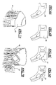
- FIGS 2A-2F are computer screens 7 showing computer-aided design (CIC) illustrations of successive steps of the design process.
- Fig. 2A shows a raw impression 8 of the patient's ear canal for the custom fit. This raw impression 8 is created by a technician first making an impression of a patient's ear canal with a two part silicon material placed in the patient's ear which hardens and is then removed. Impression 8 is then scanned with a scanner 9.
- Commercially available scanners may be used for this purpose such as the Minolta Sailor 3 Scanner with related software.
- the scanner 9 and related software outputs what is known as an STL file 9A based on a cloud of points (point cloud) at an outer periphery of the impression 8.
- An STL file is well known in this field and represents a 3D point cloud image.
- the STL file raw impression image is illustrated at 17 on the computer screen illustration of Fig. 2A .
- Figs. 2A-2F represent a semi-automated method of fabrication.
- Fig. 2B thereafter as shown in Fig. 2B , using the raw impression image 17 in Fig. 2A , an operator manually extracts a portion of the raw impression image to create a detail image 18 of the raw impression image 17.
- This detail image is similar to that employed in the construction of a prior art CIC hearing aid shell.
- the modeling and detailing of the raw impression image can be performed by commercially available software known in the prior art such as the 3SHAPE modeling software.
- the receiver shell section 14A along with the short mounting shell section 14D and expanded shell section 14B form the hearing aid shell 14.
- the operator manually shrinks the shell 14 down and around the hearing aid components comprising the receiver and the other hearing aid components like a "shrink fit".
- Fig. 2D the shell 14 which has been preshrunk in Fig. 2C is now cut to provide a gap in which the receiver shell section 14A is to be placed between the expanded section 14B and short mounting shell section 14D which receives the mushroom cap 12.
- the receiver section 14C is merged to one end of the expanded section 14B and also receives the short mounting section 14D at the other end.
- the finished product is provided showing the mushroom cap 12on the short mounting section 14D, the receiver 18 comprising receiver modules 18A, 18B received in the receiver shell section 14C, and the expanded shell section 14B resulting in the finished product (shell 14 connected to mushroom mounting element or cap 12).
- a fully automated method which automatically shrinks the outer shell 14 to the components by using fixed geometries is provided.
- a clearance is provided between the shell (hearing aid outer housing) and the ear canal that provides the open fit previously described.
- FIG. 3 A flowchart of the first and second embodiments is shown in Fig. 3 .
- the point cloud is loaded.
- the rough detail to the desired instrument type is provided.
- components are assembled/arranged.
- the shell is shrunk via the slider bar (embodiment 1) or via 3D spline (embodiment 2).
- decision block 24 if there is a collision, then the shell is again shrunk. If there is no collision, as shown at step 25 a smoothing algorithm is applied. Finally, at step 26, the final detail/touch-up occurs.
- Figs. 4A-4E show how the shell is shrunk to fit the components and thus provide a gap between the shell 14 and the ear canal sidewall 11 B (see also Fig. 1 ).
- Fig. 4A illustrates the starting shell 27 which is about the size of the ear canal.
- the center line is computed, and the shell is sectioned into sectors 28 perpendicular to the center line CL.
- Fig. 4C the slider bar 29 is moved and each sector 28 will shrink as shown at 28A until collision of that portion of the shell with the component is detected.
- Fig. 4D the operator will exercise caution to ensure embedded components can be assembled.
- a smoothing algorithm is applied with a cleanup using existing tools where necessary.
- the completed cleaned up shrunken shell is shown at 30.
- FIG. 5A shows the starting shell 31.
- Fig. 5B spline points at 32 are added.
- spline points allow the user to grab these spline points and adjust the shape of the shell as shown at 33.
- Fig. 6A the shell 35 of the hearing aid with components therein is illustrated.
- Fig. 6B the user is able to use the detailing tool where the user selects a section 36 of the shell that needs to be modified.
- adjustment points 37 are added to the shell in the section 36 to be modified which allows the user to adjust the shell using these points 37. There is no creating of splines.
- Fig. 6D the shell has been adjusted as shown at 38 by moving the points 37 downwardly to 37A, for example to modify the shell.
- the final result is an STL file which is now sent to rapid prototype equipment such as SLA Viper or other 3D printers (also known as SLA stereolithography printers).
- SLA Viper or other 3D printers also known as SLA stereolithography printers.
- Such printers are well known in the art and accept STL files to create three dimensional final objects, in this case a fabricated shell.
- the commercially available 3D printer shown in Fig. 8 builds the shell 40 on top of a support material 41.
- the building of the shell and the use of support material with the known prior art 3D printer such as 39 (the known SLA Viper, for example) is known in the art.
- Fig. 9 shows the mushroom cap or dome (mounting element) 12, the vent apertures 12a, the receiver 18 formed of modules 18A and 18B and the receiver shell section 14C of shell 14 (forming a pocket) in a side view.
- the receiver 18 is installed into the receiver shell section 14A.
- RTV is used and also a mechanical latch system is provided to assure reliability and serviceability.
- This mechanical latch system is shown as a female latch element 43 and a male latch element 44 in detail in Fig. 10 .
- a male latch element is provided on each receiver module 18A, 18B and a respective female latch element 43 is provided at opposite sides of the receiver shell section 14C.
- male and female latch elements tongue and groove elements may be employed.
- a method for manufacturing a small hearing aid which fits completely in an ear canal of a user comprising the steps of: providing a mounting element with at least one airflow aperture for use at one end of the hearing aid for mounting near an ear drum of the patient and having an outer periphery which contacts inner walls of the ear canal near the ear drum; providing a raw impression image of the user's ear canal; shaping a shell as an outer housing of the hearing aid to more closely surround components of the hearing aid and to provide a gap between the ear canal inner walls and the shell to allow flow of air to and from the ear drum when the hearing aid is mounted in the ear canal, by said mounting element; and said shaping of the shell comprising displaying an image on a computer screen of an initial shell with said components of the hearing aid in the initial shell and then shrinking the image of the initial shell toward the components to more closely surround the components, and wherein the initial shell image on the computer screen initially approximates a size of the ear canal from the raw impression image.
- the components of the hearing aid may comprise a receiver and other components.
- the shell may further comprise a receiver shell section for housing the receiver and an expanded shell section housing the other components.
- the shell may further comprise a short mounting section which connects the mounting element to the receiver shell section.
Abstract
Description
- This application claims the benefit of
U.S. Provisional Application No. 61/041,336, filed April 1, 2008 - It is known to provide a completely-in-the-canal (CIC) hearing instrument (hearing aid) in which an outer housing known as a shell of the hearing aid, is formed in a shape corresponding to the ear canal. An outside surface of that shell is in contact with substantial portions of an inner surface of the ear canal. With such CIC hearing aids, because the hearing aid housing is substantially in contact with the ear canal, a vent cavity inside the shell is provided to allow air flow through the ear canal and thus permit pressure to be equalized between the outside and the inside of the ear drum. This vent cavity or channel also reduces occlusion effects and operation of the hearing aid. Occlusion effects are known in this industry as being a change in hearing acoustics which sounds like being in a tunnel.
- It is an object to decrease the size of the CIC hearing aid so that it is even smaller than the conventional CIC hearing aid.
- A small hearing aid is provided which fits completely in an ear canal of a user wherein a shell as an outer housing of the hearing aid is shaped to closely surround components of the hearing aid to provide a gap between the hearing canal inner walls and the shell to allow flow of air when the hearing aid is mounted in the ear by a mounting element connected to the shell. The mounting element is provided with at least one aperture to allow the air flow. In a fabrication method, an image of the shell is shrunk to closely surround the hearing aid components while maintaining a shape of the ear canal to assure a custom fit.
-
-
Fig. 1 is a side view of the small CIC hearing aid of the preferred embodiment; -
Figs. 2A-2F illustrate method steps in the fabrication of the small CIC hearing aid with a semi-automated method; -
Fig. 3 is a flow chart for both first and second embodiments of a substantially fully automated method of fabrication of the small CIC hearing aid; -
Figs.4A-4E are illustrations of the first embodiment of the fully automated method for fabrication of the small CIC hearing aid; -
Figs. 5A-5D are cross-sectional views showing a user adding spline points on the hearing aid shell according to the second embodiment of the fully automated method; -
Figs. 6A-6D illustrate how a user is able to use a detailing tool where the hearing aid shell needs to be modified; -
Figs. 7A and 7B illustrate views of building of the hearing aid shell using a 3D printer in a stereolithography process; -
Fig. 8 shows aprior art 3D stereolithography printer machine for fabricating the small hearing aid shell according to the preferred embodiment; -
Fig. 9 is a side view of a mushroom cap mounting element, receiver, and receiver shell section having a latching mechanism for the small hearing aid; and -
Fig. 10 is a detail of the latching mechanism ofFigure 9 to latch the receiver shell section to one end of the receiver. - For the purposes of promoting an understanding of the principles of the invention, reference will now be made to preferred embodiments/best mode illustrated in the drawings and specific language will be used to describe the same. It will nevertheless be understood that no limitation of the scope of the invention is thereby intended, and such alterations and further modifications in the illustrated device and such further applications of the principles of the invention as illustrated as would normally occur to one skilled in the art to which the invention relates are included.
- The preferred embodiments allow fabrication of a CIC hearing aid which is smaller than the prior art CIC hearing aid. The small CIC hearing aid fabricated by the preferred embodiments generally has a profile which is smaller than the ear canal, since the hearing aid shell is modeled around the components of the hearing aid such that the shell is "shrunk" to more closely approximate the size of the hearing aid components, rather than being sized to the ear canal inner walls. A mushroom cap is used to secure the small hearing aid inside the ear canal. This mushroom cap has an outer periphery contacting inner side walls of the ear canal near the ear drum and air vent apertures are provided therein as described hereafter.
-
Fig. 1 generally illustrates at 10 a small CIC hearing aid fitted within theear canal 11 with the ear canal being shown in dashed lines. The hearing aid is shown in side view. Themushroom cap 12, functioning as a mounting element for the hearing aid, is positioned near theear drum 11 A in theear canal 11. Thismounting element 12 has a plurality ofvent apertures 12A allowing airflow through the ear canal to and from theear drum 11A to ensure that pressure on theear drum 11 is equalized and also to improve overall acoustical comfort of thehearing aid 10. Because there is agap 13 between theinner wall 11 B of theear canal 11 and remaining portions of thesmall hearing aid 10, air flowing through thevent apertures 12A can freely pass through thegap 13 betweensidewall 11 B and the hearing aid portions extending from the cap mounting element. - The
hearing aid 10 has anouter shell 14 formed of areceiver shell section 14A having a receiver 18 (Fig. 9 ) connected to ashort mounting section 14D at one end and ashell section 14B housing additional components. Also inFig. 1 , an optionalcurved shell section 14C not employed inFigs. 2C-2F may also be provided as a transition section. - The fabrication of the small hearing aid will now be described with reference to
Figs. 2A-2F ,3 ,4A-4E ,5A-5D ,6A-6D ,7, and 8 . With the fabrication method, fixed geometries are used to shrink the outer shell to fit the internal components while maintaining a clearance between the shell and the ear canal to provide what is known as an open fit. -
Figures 2A-2F arecomputer screens 7 showing computer-aided design (CIC) illustrations of successive steps of the design process.Fig. 2A shows araw impression 8 of the patient's ear canal for the custom fit. Thisraw impression 8 is created by a technician first making an impression of a patient's ear canal with a two part silicon material placed in the patient's ear which hardens and is then removed.Impression 8 is then scanned with a scanner 9. Commercially available scanners may be used for this purpose such as the Minolta Sailor 3 Scanner with related software. The scanner 9 and related software outputs what is known as anSTL file 9A based on a cloud of points (point cloud) at an outer periphery of theimpression 8. An STL file is well known in this field and represents a 3D point cloud image. The STL file raw impression image is illustrated at 17 on the computer screen illustration ofFig. 2A . -
Figs. 2A-2F represent a semi-automated method of fabrication. - Creating the raw impression and scanning the raw impression to create an STL file is known prior art.
- Thereafter as shown in
Fig. 2B , using theraw impression image 17 inFig. 2A , an operator manually extracts a portion of the raw impression image to create adetail image 18 of theraw impression image 17. This detail image is similar to that employed in the construction of a prior art CIC hearing aid shell. InFig. 2B , the modeling and detailing of the raw impression image can be performed by commercially available software known in the prior art such as the 3SHAPE modeling software. - In
Fig. 2C , thereceiver shell section 14A along with the shortmounting shell section 14D and expandedshell section 14B form thehearing aid shell 14. Here, the operator manually shrinks theshell 14 down and around the hearing aid components comprising the receiver and the other hearing aid components like a "shrink fit". - In
Fig. 2D theshell 14 which has been preshrunk inFig. 2C is now cut to provide a gap in which thereceiver shell section 14A is to be placed between the expandedsection 14B and shortmounting shell section 14D which receives themushroom cap 12. - In
Fig. 2E , thereceiver section 14C is merged to one end of the expandedsection 14B and also receives theshort mounting section 14D at the other end. - In
Fig. 2F , the finished product is provided showing the mushroom cap 12on theshort mounting section 14D, thereceiver 18 comprisingreceiver modules receiver shell section 14C, and the expandedshell section 14B resulting in the finished product (shell 14 connected to mushroom mounting element or cap 12). - As an alternative to the semiautomatic mode involving manual manipulation by an operator, a fully automated method which automatically shrinks the
outer shell 14 to the components by using fixed geometries is provided. As in the case of the semi-automatic method, with the automatic method a clearance is provided between the shell (hearing aid outer housing) and the ear canal that provides the open fit previously described. - Three alternative embodiments are provided for the fully automated method. A flowchart of the first and second embodiments is shown in
Fig. 3 . As illustrated there, atstep 19 the point cloud is loaded. Atstep 20, the rough detail to the desired instrument type is provided. Atstep 21 components are assembled/arranged. Atstep 22 the shell is shrunk via the slider bar (embodiment 1) or via 3D spline (embodiment 2). - At step 23 a check is made for collision between the components and the shell. At
decision block 24, if there is a collision, then the shell is again shrunk. If there is no collision, as shown at step 25 a smoothing algorithm is applied. Finally, atstep 26, the final detail/touch-up occurs. -
Figs. 4A-4E show how the shell is shrunk to fit the components and thus provide a gap between theshell 14 and theear canal sidewall 11 B (see alsoFig. 1 ).Fig. 4A illustrates the startingshell 27 which is about the size of the ear canal. InFig. 4B , the center line is computed, and the shell is sectioned intosectors 28 perpendicular to the center line CL. InFig. 4C , theslider bar 29 is moved and eachsector 28 will shrink as shown at 28A until collision of that portion of the shell with the component is detected. InFig. 4D , the operator will exercise caution to ensure embedded components can be assembled. InFig. 4E , a smoothing algorithm is applied with a cleanup using existing tools where necessary. The completed cleaned up shrunken shell is shown at 30. - With
embodiment 1 of the fully automated method, the following occurs: - 1. The software takes as an input an STL file that represents the receiver shell section around the receiver.
- 2. The software positions the receiver shell section as deep as possible inside a virtual cast representing the inside of the ear canal.
- 3. The software allows the user to position the other hearing aid components inside the virtual cast (ear canal), and shows a clearance equal to the shell thickness value between the other components and the virtual cast (ear canal).
- 4. The software grows the STL shell section towards the other components in such a way that the expanded shell section touches the virtual cast (ear canal) along the longest axis of the canal and has some free space between the expanded shell section and the virtual cast (ear canal) along the short axis of the canal.
- 5. The shrink wraparound the receiver and other components generated as a result of this operation shall have a minimum space required to cover the hearing aid receiver and other components.
- 6. The software ensures that on the face plane the shrink wrapped shell shall touch the virtual cast (ear canal) along the long axis of the canal.
- 7. The software ensures that the shrink wrap shall not collide with the virtual cast (ear canal). This ensures that the shell does not flop in the ear.
- A second embodiment for the fully automated method is shown in
Figs. 5A-5D. Fig. 5A shows the startingshell 31. InFig. 5B , spline points at 32 are added. - In
Fig. 5C spline points allow the user to grab these spline points and adjust the shape of the shell as shown at 33. - In
Fig. 5D theshrunken shell 34 results. - In the second embodiment for the fully automated method, the following steps occur:
- 1. The software takes as an input an STL file format that represents the receiver shell section and an STL file that represents the expanded shell section around the other components.
- 2. The software positions the STL file that represents the receiver shell section around the receiver as deep as possible inside the virtual cast (ear canal) without collisions with the virtual cast (ear canal).
- 3. The software positions the STL file that represents the expanded shell section around the other components as deep as possible inside the virtual cast without collisions with the virtual cast (ear canal) and an STL file that represents the receiver shell section around the receiver.
- 4. The software grows an STL file that represents the expanded shell section around other components in the direction of an STL file that represents the receiver shell section around the receiver in such way that no collision with the virtual cast (ear canal) occur.
- 5. The software grows an STL file that represents the receiver shell section around the receiver in the direction of an STL file that represents the expanded shell section around the other components in such a way that no collision with the virtual cast (ear canal) will occur.
- 6. The software ensures that the growing surfaces of an STL file that represents the expanded shell section around the other components and an STL file that represents the receiver shell section around the receiver will meet in-between two STL files and allow the seamless merge of two STL files to form a single shell,
- 7. The software merges the grown surfaces of an STL file that represents the receiver shell section around the receiver with the grown surface of an STL file that represents the expanded shell section around the other components to form a single hearing aid shell.
- A third embodiment for the fully automated method will now be described with reference to
Figures 6A-6D . - In
Fig. 6A , theshell 35 of the hearing aid with components therein is illustrated. - In
Fig. 6B , the user is able to use the detailing tool where the user selects asection 36 of the shell that needs to be modified. - In
Fig. 6C , adjustment points 37 are added to the shell in thesection 36 to be modified which allows the user to adjust the shell using thesepoints 37. There is no creating of splines. - In
Fig. 6D , the shell has been adjusted as shown at 38 by moving thepoints 37 downwardly to 37A, for example to modify the shell. - With the third embodiment for the fully automated method illustrated in
Figs. 6A-6D , the following steps occur: - 1. The software takes as an input for this approach an STL file that represents the generic small hearing aid shell.
- 2. The software positions the generic small hearing aid shell in the virtual cast (ear canal) in such a way that no collisions occur before an area where bending of the shell is to occur.
- 3. Software bends the hearing aid shell in such a way that the bent hearing aid shell fits in a virtual cast (ear canal) without collisions.
- For either the semi-automated or fully automated method, the final result is an STL file which is now sent to rapid prototype equipment such as SLA Viper or other 3D printers (also known as SLA stereolithography printers). Such printers are well known in the art and accept STL files to create three dimensional final objects, in this case a fabricated shell.
- As shown in the two view of
Figs. 7A and 7B , the commercially available 3D printer shown inFig. 8 builds theshell 40 on top of asupport material 41. The building of the shell and the use of support material with the knownprior art 3D printer such as 39 (the known SLA Viper, for example) is known in the art. -
Fig. 9 shows the mushroom cap or dome (mounting element) 12, the vent apertures 12a, thereceiver 18 formed ofmodules receiver shell section 14C of shell 14 (forming a pocket) in a side view. Thereceiver 18 is installed into thereceiver shell section 14A. In order to ensure that thereceiver 18 is secured in the pocket-likereceiver shell section 14A, RTV is used and also a mechanical latch system is provided to assure reliability and serviceability. This mechanical latch system is shown as afemale latch element 43 and amale latch element 44 in detail inFig. 10 . A male latch element is provided on eachreceiver module female latch element 43 is provided at opposite sides of thereceiver shell section 14C. As an alternative to male and female latch elements tongue and groove elements may be employed. - A method for manufacturing a small hearing aid which fits completely in an ear canal of a user, comprising the steps of: providing a mounting element with at least one airflow aperture for use at one end of the hearing aid for mounting near an ear drum of the patient and having an outer periphery which contacts inner walls of the ear canal near the ear drum; providing a raw impression image of the user's ear canal; shaping a shell as an outer housing of the hearing aid to more closely surround components of the hearing aid and to provide a gap between the ear canal inner walls and the shell to allow flow of air to and from the ear drum when the hearing aid is mounted in the ear canal, by said mounting element; and said shaping of the shell comprising displaying an image on a computer screen of an initial shell with said components of the hearing aid in the initial shell and then shrinking the image of the initial shell toward the components to more closely surround the components, and wherein the initial shell image on the computer screen initially approximates a size of the ear canal from the raw impression image.
- The components of the hearing aid may comprise a receiver and other components. The shell may further comprise a receiver shell section for housing the receiver and an expanded shell section housing the other components. The shell may further comprise a short mounting section which connects the mounting element to the receiver shell section.
- While preferred embodiments have been illustrated and described in detail in the drawings and foregoing description, the same are to be considered as illustrative and not restrictive in character, it being understood that only the preferred embodiments have been shown and described and that all changes and modifications that come within the scope of the invention as claimed by the attached claims.
Claims (15)
- A method for manufacturing a small hearing aid which fits completely in an ear canal of a user, comprising the steps of:providing a mounting element for use at one end of the hearing aid for mounting near an ear drum of the patient and having an outer periphery which contacts inner walls of the ear canal near the ear drum; andshaping a shell as an outer housing of the hearing aid to more closely surround components of the hearing aid and to provide a gap between the hearing canal inner walls and the shell to allow flow of air to and from the ear drum when the hearing aid is mounted in the ear canal by said mounting element.
- A method of claim 1 wherein said mounting element is provided with at least one vent aperture to permit airflow through said gap.
- A method of claim 2 wherein the mounting element comprises a dome-shaped cap having a plurality of vent apertures therein.
- A method of any one of the preceding claims including the step of displaying an image on a computer screen of an initial shell with said components of the hearing aid in the initial shell and then shrinking the image of the initial shell toward the components to more closely surround the components.
- A method of claim 4 wherein the image of the initial shell on the computer screen initially approximates a size of the ear canal and the shell is then shrunk down to more closely surround the components of the hearing aid, and/or wherein the hearing aid components comprise a receiver and other components, and wherein a receiver section of the shell is shrunk down to more closely surround the receiver and an expanded section of the shell is shrunk down to closely surround the other components, and/or wherein the image of the shell on the computer screen is divided into segments and individual segments are shrunk down to closely surround the hearing aid components.
- A method of claim 4 wherein points at a periphery of the shell image are moved toward the components.
- A method of claim 4 wherein a check is made for a collision between the shell and at least one of the components in association with the shrinking.
- A method of claim 4 wherein a scanned image of an impression of the user's ear canal is input to a computer and used by the computer for providing the initial shell image which is then shrunk toward the components.
- A small hearing aid for mounting completely in an ear canal of a user, comprising:a mounting element having a periphery dimensioned to contact inside walls of the ear canal of the user near the ear drum;a shell as an outer housing which encloses and is closely adjacent to components of the hearing aid and dimensioned such that the shell has a spacing from inner walls of the ear canal to form a gap between the shell and the inner walls; andat least one vent aperture in the mounting element to permit air flow through said gap between the shell and the ear canal inner walls.
- A hearing aid of claim 9 wherein the components of the hearing aid comprise a receiver and other components and wherein the shell comprises a receiver shell section for housing the receiver and an expanded shell section housing the other components and wherein the shell further comprises a short mounting section which connects the mounting element to the receiver shell section.
- A hearing aid of claim 9 wherein the mounting element comprises a mushroom- shaped cap.
- A computer-readable medium comprising a computer program that is used for designing a shell of a small hearing aid which fits completely in an ear canal of a user, said computer program performing the steps of:displaying an image of an initial shell for the hearing aid on a computer screen; andshrinking the image of the initial shell towards components of the hearing aid to provide a gap between inner walls of the ear canal and the shell to allow flow of air therethrough when the hearing aid is mounted in the ear by a mounting element connected to said shell positioned near an ear drum of the user.
- A computer-readable medium of claim 12 wherein the computer program receives an image of a raw impression of the user's ear canal and initially dimensions the shell to the ear canal prior to said shrinking of the initial shell image or wherein the program divides the initial shell image into sectors and shrinks the sectors toward the components.
- A computer-readable medium of claim 12 wherein the program moves points on the initial shell toward the components of the hearing aid.
- A computer-readable medium of claim 12 wherein as the initial shell is shrunk, the program detects whether or not a collision occurs with at least one of the components and the shell during the shrinking step.
Applications Claiming Priority (2)
| Application Number | Priority Date | Filing Date | Title |
|---|---|---|---|
| US4133608P | 2008-04-01 | 2008-04-01 | |
| US12/183,306 US8199952B2 (en) | 2008-04-01 | 2008-07-31 | Method for adaptive construction of a small CIC hearing instrument |
Publications (3)
| Publication Number | Publication Date |
|---|---|
| EP2107832A2 true EP2107832A2 (en) | 2009-10-07 |
| EP2107832A3 EP2107832A3 (en) | 2010-01-20 |
| EP2107832B1 EP2107832B1 (en) | 2013-06-12 |
Family
ID=40849218
Family Applications (1)
| Application Number | Title | Priority Date | Filing Date |
|---|---|---|---|
| EP09154951.9A Active EP2107832B1 (en) | 2008-04-01 | 2009-03-12 | A method for adaptive construction of a small CIC hearing instrument |
Country Status (3)
| Country | Link |
|---|---|
| US (1) | US8199952B2 (en) |
| EP (1) | EP2107832B1 (en) |
| DK (1) | DK2107832T3 (en) |
Cited By (2)
| Publication number | Priority date | Publication date | Assignee | Title |
|---|---|---|---|---|
| WO2016037634A1 (en) * | 2014-09-08 | 2016-03-17 | Sonova Ag | A method for producing a hearing device shell, a hearing device shell and a hearing device |
| EP3249953A1 (en) | 2016-05-24 | 2017-11-29 | Sivantos Pte. Ltd. | Standard tip for a standard earpiece |
Families Citing this family (80)
| Publication number | Priority date | Publication date | Assignee | Title |
|---|---|---|---|---|
| US8554352B2 (en) * | 2009-05-07 | 2013-10-08 | Siemens Hearing Instruments, Inc. | Method of generating an optimized venting channel in a hearing instrument |
| DE102010022323A1 (en) | 2010-06-01 | 2011-12-01 | Siemens Medical Instruments Pte. Ltd. | Deep-ear-canal hearing instrument |
| US9854372B2 (en) | 2015-08-29 | 2017-12-26 | Bragi GmbH | Production line PCB serial programming and testing method and system |
| US9843853B2 (en) | 2015-08-29 | 2017-12-12 | Bragi GmbH | Power control for battery powered personal area network device system and method |
| US9972895B2 (en) | 2015-08-29 | 2018-05-15 | Bragi GmbH | Antenna for use in a wearable device |
| US9949013B2 (en) | 2015-08-29 | 2018-04-17 | Bragi GmbH | Near field gesture control system and method |
| US10122421B2 (en) | 2015-08-29 | 2018-11-06 | Bragi GmbH | Multimodal communication system using induction and radio and method |
| US9905088B2 (en) | 2015-08-29 | 2018-02-27 | Bragi GmbH | Responsive visual communication system and method |
| US9949008B2 (en) | 2015-08-29 | 2018-04-17 | Bragi GmbH | Reproduction of ambient environmental sound for acoustic transparency of ear canal device system and method |
| US9980189B2 (en) | 2015-10-20 | 2018-05-22 | Bragi GmbH | Diversity bluetooth system and method |
| US10506322B2 (en) | 2015-10-20 | 2019-12-10 | Bragi GmbH | Wearable device onboard applications system and method |
| US10104458B2 (en) | 2015-10-20 | 2018-10-16 | Bragi GmbH | Enhanced biometric control systems for detection of emergency events system and method |
| US9866941B2 (en) | 2015-10-20 | 2018-01-09 | Bragi GmbH | Multi-point multiple sensor array for data sensing and processing system and method |
| US9980033B2 (en) | 2015-12-21 | 2018-05-22 | Bragi GmbH | Microphone natural speech capture voice dictation system and method |
| US9939891B2 (en) | 2015-12-21 | 2018-04-10 | Bragi GmbH | Voice dictation systems using earpiece microphone system and method |
| US10085091B2 (en) | 2016-02-09 | 2018-09-25 | Bragi GmbH | Ambient volume modification through environmental microphone feedback loop system and method |
| US10085082B2 (en) | 2016-03-11 | 2018-09-25 | Bragi GmbH | Earpiece with GPS receiver |
| US10045116B2 (en) | 2016-03-14 | 2018-08-07 | Bragi GmbH | Explosive sound pressure level active noise cancellation utilizing completely wireless earpieces system and method |
| US10052065B2 (en) | 2016-03-23 | 2018-08-21 | Bragi GmbH | Earpiece life monitor with capability of automatic notification system and method |
| US10015579B2 (en) | 2016-04-08 | 2018-07-03 | Bragi GmbH | Audio accelerometric feedback through bilateral ear worn device system and method |
| US10013542B2 (en) | 2016-04-28 | 2018-07-03 | Bragi GmbH | Biometric interface system and method |
| USD836089S1 (en) * | 2016-05-06 | 2018-12-18 | Bragi GmbH | Headphone |
| USD824371S1 (en) * | 2016-05-06 | 2018-07-31 | Bragi GmbH | Headphone |
| US11085871B2 (en) | 2016-07-06 | 2021-08-10 | Bragi GmbH | Optical vibration detection system and method |
| US10216474B2 (en) | 2016-07-06 | 2019-02-26 | Bragi GmbH | Variable computing engine for interactive media based upon user biometrics |
| US10201309B2 (en) | 2016-07-06 | 2019-02-12 | Bragi GmbH | Detection of physiological data using radar/lidar of wireless earpieces |
| US10555700B2 (en) | 2016-07-06 | 2020-02-11 | Bragi GmbH | Combined optical sensor for audio and pulse oximetry system and method |
| US10045110B2 (en) | 2016-07-06 | 2018-08-07 | Bragi GmbH | Selective sound field environment processing system and method |
| US10582328B2 (en) | 2016-07-06 | 2020-03-03 | Bragi GmbH | Audio response based on user worn microphones to direct or adapt program responses system and method |
| US10888039B2 (en) | 2016-07-06 | 2021-01-05 | Bragi GmbH | Shielded case for wireless earpieces |
| US10165350B2 (en) | 2016-07-07 | 2018-12-25 | Bragi GmbH | Earpiece with app environment |
| US10621583B2 (en) | 2016-07-07 | 2020-04-14 | Bragi GmbH | Wearable earpiece multifactorial biometric analysis system and method |
| US10516930B2 (en) | 2016-07-07 | 2019-12-24 | Bragi GmbH | Comparative analysis of sensors to control power status for wireless earpieces |
| US10158934B2 (en) | 2016-07-07 | 2018-12-18 | Bragi GmbH | Case for multiple earpiece pairs |
| US10587943B2 (en) | 2016-07-09 | 2020-03-10 | Bragi GmbH | Earpiece with wirelessly recharging battery |
| US10397686B2 (en) | 2016-08-15 | 2019-08-27 | Bragi GmbH | Detection of movement adjacent an earpiece device |
| US10977348B2 (en) | 2016-08-24 | 2021-04-13 | Bragi GmbH | Digital signature using phonometry and compiled biometric data system and method |
| US10104464B2 (en) | 2016-08-25 | 2018-10-16 | Bragi GmbH | Wireless earpiece and smart glasses system and method |
| US10409091B2 (en) | 2016-08-25 | 2019-09-10 | Bragi GmbH | Wearable with lenses |
| US11086593B2 (en) | 2016-08-26 | 2021-08-10 | Bragi GmbH | Voice assistant for wireless earpieces |
| US10313779B2 (en) | 2016-08-26 | 2019-06-04 | Bragi GmbH | Voice assistant system for wireless earpieces |
| US11200026B2 (en) | 2016-08-26 | 2021-12-14 | Bragi GmbH | Wireless earpiece with a passive virtual assistant |
| US10887679B2 (en) | 2016-08-26 | 2021-01-05 | Bragi GmbH | Earpiece for audiograms |
| US10200780B2 (en) | 2016-08-29 | 2019-02-05 | Bragi GmbH | Method and apparatus for conveying battery life of wireless earpiece |
| US11490858B2 (en) | 2016-08-31 | 2022-11-08 | Bragi GmbH | Disposable sensor array wearable device sleeve system and method |
| USD822645S1 (en) | 2016-09-03 | 2018-07-10 | Bragi GmbH | Headphone |
| US10598506B2 (en) | 2016-09-12 | 2020-03-24 | Bragi GmbH | Audio navigation using short range bilateral earpieces |
| US10580282B2 (en) | 2016-09-12 | 2020-03-03 | Bragi GmbH | Ear based contextual environment and biometric pattern recognition system and method |
| US10852829B2 (en) | 2016-09-13 | 2020-12-01 | Bragi GmbH | Measurement of facial muscle EMG potentials for predictive analysis using a smart wearable system and method |
| US11283742B2 (en) | 2016-09-27 | 2022-03-22 | Bragi GmbH | Audio-based social media platform |
| US10460095B2 (en) | 2016-09-30 | 2019-10-29 | Bragi GmbH | Earpiece with biometric identifiers |
| US10049184B2 (en) | 2016-10-07 | 2018-08-14 | Bragi GmbH | Software application transmission via body interface using a wearable device in conjunction with removable body sensor arrays system and method |
| US10771877B2 (en) | 2016-10-31 | 2020-09-08 | Bragi GmbH | Dual earpieces for same ear |
| US10942701B2 (en) | 2016-10-31 | 2021-03-09 | Bragi GmbH | Input and edit functions utilizing accelerometer based earpiece movement system and method |
| US10455313B2 (en) | 2016-10-31 | 2019-10-22 | Bragi GmbH | Wireless earpiece with force feedback |
| US10698983B2 (en) | 2016-10-31 | 2020-06-30 | Bragi GmbH | Wireless earpiece with a medical engine |
| US10117604B2 (en) | 2016-11-02 | 2018-11-06 | Bragi GmbH | 3D sound positioning with distributed sensors |
| US10617297B2 (en) | 2016-11-02 | 2020-04-14 | Bragi GmbH | Earpiece with in-ear electrodes |
| US10821361B2 (en) | 2016-11-03 | 2020-11-03 | Bragi GmbH | Gaming with earpiece 3D audio |
| US10205814B2 (en) | 2016-11-03 | 2019-02-12 | Bragi GmbH | Wireless earpiece with walkie-talkie functionality |
| US10062373B2 (en) | 2016-11-03 | 2018-08-28 | Bragi GmbH | Selective audio isolation from body generated sound system and method |
| US10225638B2 (en) | 2016-11-03 | 2019-03-05 | Bragi GmbH | Ear piece with pseudolite connectivity |
| US10045112B2 (en) | 2016-11-04 | 2018-08-07 | Bragi GmbH | Earpiece with added ambient environment |
| US10063957B2 (en) | 2016-11-04 | 2018-08-28 | Bragi GmbH | Earpiece with source selection within ambient environment |
| US10045117B2 (en) | 2016-11-04 | 2018-08-07 | Bragi GmbH | Earpiece with modified ambient environment over-ride function |
| US10058282B2 (en) | 2016-11-04 | 2018-08-28 | Bragi GmbH | Manual operation assistance with earpiece with 3D sound cues |
| US10506327B2 (en) | 2016-12-27 | 2019-12-10 | Bragi GmbH | Ambient environmental sound field manipulation based on user defined voice and audio recognition pattern analysis system and method |
| US10405081B2 (en) | 2017-02-08 | 2019-09-03 | Bragi GmbH | Intelligent wireless headset system |
| US10582290B2 (en) | 2017-02-21 | 2020-03-03 | Bragi GmbH | Earpiece with tap functionality |
| US10771881B2 (en) | 2017-02-27 | 2020-09-08 | Bragi GmbH | Earpiece with audio 3D menu |
| US11380430B2 (en) | 2017-03-22 | 2022-07-05 | Bragi GmbH | System and method for populating electronic medical records with wireless earpieces |
| US10575086B2 (en) | 2017-03-22 | 2020-02-25 | Bragi GmbH | System and method for sharing wireless earpieces |
| US11544104B2 (en) | 2017-03-22 | 2023-01-03 | Bragi GmbH | Load sharing between wireless earpieces |
| US11694771B2 (en) | 2017-03-22 | 2023-07-04 | Bragi GmbH | System and method for populating electronic health records with wireless earpieces |
| US10708699B2 (en) | 2017-05-03 | 2020-07-07 | Bragi GmbH | Hearing aid with added functionality |
| US11116415B2 (en) | 2017-06-07 | 2021-09-14 | Bragi GmbH | Use of body-worn radar for biometric measurements, contextual awareness and identification |
| US11013445B2 (en) | 2017-06-08 | 2021-05-25 | Bragi GmbH | Wireless earpiece with transcranial stimulation |
| US10344960B2 (en) | 2017-09-19 | 2019-07-09 | Bragi GmbH | Wireless earpiece controlled medical headlight |
| US11272367B2 (en) | 2017-09-20 | 2022-03-08 | Bragi GmbH | Wireless earpieces for hub communications |
| JP1693614S (en) * | 2020-12-04 | 2021-08-30 |
Family Cites Families (6)
| Publication number | Priority date | Publication date | Assignee | Title |
|---|---|---|---|---|
| US6259962B1 (en) | 1999-03-01 | 2001-07-10 | Objet Geometries Ltd. | Apparatus and method for three dimensional model printing |
| US6724902B1 (en) | 1999-04-29 | 2004-04-20 | Insound Medical, Inc. | Canal hearing device with tubular insert |
| US6850334B1 (en) | 2000-01-18 | 2005-02-01 | Objet Geometries Ltd | System and method for three dimensional model printing |
| US7300619B2 (en) | 2000-03-13 | 2007-11-27 | Objet Geometries Ltd. | Compositions and methods for use in three dimensional model printing |
| US20020196954A1 (en) | 2001-06-22 | 2002-12-26 | Marxen Christopher J. | Modeling and fabrication of three-dimensional irregular surfaces for hearing instruments |
| US20030151167A1 (en) | 2002-01-03 | 2003-08-14 | Kritchman Eliahu M. | Device, system and method for accurate printing of three dimensional objects |
-
2008
- 2008-07-31 US US12/183,306 patent/US8199952B2/en active Active
-
2009
- 2009-03-12 DK DK09154951.9T patent/DK2107832T3/en active
- 2009-03-12 EP EP09154951.9A patent/EP2107832B1/en active Active
Non-Patent Citations (1)
| Title |
|---|
| None |
Cited By (4)
| Publication number | Priority date | Publication date | Assignee | Title |
|---|---|---|---|---|
| WO2016037634A1 (en) * | 2014-09-08 | 2016-03-17 | Sonova Ag | A method for producing a hearing device shell, a hearing device shell and a hearing device |
| EP3249953A1 (en) | 2016-05-24 | 2017-11-29 | Sivantos Pte. Ltd. | Standard tip for a standard earpiece |
| DE102016208939A1 (en) | 2016-05-24 | 2017-11-30 | Sivantos Pte. Ltd. | Standard attachment for a standard earpiece |
| US10334375B2 (en) | 2016-05-24 | 2019-06-25 | Sivantos Pte. Ltd. | Standard attachment for a standard earpiece and standard earpiece |
Also Published As
| Publication number | Publication date |
|---|---|
| EP2107832A3 (en) | 2010-01-20 |
| DK2107832T3 (en) | 2013-06-24 |
| US20090245559A1 (en) | 2009-10-01 |
| EP2107832B1 (en) | 2013-06-12 |
| US8199952B2 (en) | 2012-06-12 |
Similar Documents
| Publication | Publication Date | Title |
|---|---|---|
| EP2107832B1 (en) | A method for adaptive construction of a small CIC hearing instrument | |
| EP1356709B1 (en) | Manufacturing methods and systems for rapid production of hearing-aid shells | |
| US20020196954A1 (en) | Modeling and fabrication of three-dimensional irregular surfaces for hearing instruments | |
| JP5823966B2 (en) | Individually adjusted soft components | |
| AU2002211860A1 (en) | Manufacturing methods and systems for rapid production of hearing-aid shells | |
| EP1858293B1 (en) | System comprising an automated tool and appertaining method for hearing aid design | |
| EP2834750B1 (en) | Method for estimating the shape of an individual ear | |
| US10021496B2 (en) | Method and system for creating non-occluding earpieces | |
| EP2249585B1 (en) | Method of generating an optimized venting channel in a hearing instrument | |
| DK1898673T3 (en) | Computerized method of compliance with physical limitation in the design of an ITE hearing aid | |
| EP2190220A2 (en) | Method and process for automating the design of a locking mechanism for a hearing instrument | |
| EP2048895B1 (en) | A computerized rule-based binaural modeling system and method for hearing aid design | |
| US8494814B2 (en) | Methods for inlet and outlet modelling of vent as large as possible for hearing aid devices | |
| Gao et al. | Design and realization of hearing aids based 3D rapid shell mold ing CADCAM |
Legal Events
| Date | Code | Title | Description |
|---|---|---|---|
| PUAI | Public reference made under article 153(3) epc to a published international application that has entered the european phase |
Free format text: ORIGINAL CODE: 0009012 |
|
| AK | Designated contracting states |
Kind code of ref document: A2 Designated state(s): AT BE BG CH CY CZ DE DK EE ES FI FR GB GR HR HU IE IS IT LI LT LU LV MC MK MT NL NO PL PT RO SE SI SK TR |
|
| AX | Request for extension of the european patent |
Extension state: AL BA RS |
|
| PUAL | Search report despatched |
Free format text: ORIGINAL CODE: 0009013 |
|
| AK | Designated contracting states |
Kind code of ref document: A3 Designated state(s): AT BE BG CH CY CZ DE DK EE ES FI FR GB GR HR HU IE IS IT LI LT LU LV MC MK MT NL NO PL PT RO SE SI SK TR |
|
| AX | Request for extension of the european patent |
Extension state: AL BA RS |
|
| 17P | Request for examination filed |
Effective date: 20100524 |
|
| 17Q | First examination report despatched |
Effective date: 20100616 |
|
| AKX | Designation fees paid |
Designated state(s): AT BE BG CH CY CZ DE DK EE ES FI FR GB GR HR HU IE IS IT LI LT LU LV MC MK MT NL NO PL PT RO SE SI SK TR |
|
| REG | Reference to a national code |
Ref country code: DE Ref legal event code: R079 Ref document number: 602009016343 Country of ref document: DE Free format text: PREVIOUS MAIN CLASS: H04R0025020000 Ipc: H04R0025000000 |
|
| GRAP | Despatch of communication of intention to grant a patent |
Free format text: ORIGINAL CODE: EPIDOSNIGR1 |
|
| RIC1 | Information provided on ipc code assigned before grant |
Ipc: H04R 25/00 20060101AFI20120920BHEP |
|
| GRAS | Grant fee paid |
Free format text: ORIGINAL CODE: EPIDOSNIGR3 |
|
| GRAA | (expected) grant |
Free format text: ORIGINAL CODE: 0009210 |
|
| RAP1 | Party data changed (applicant data changed or rights of an application transferred) |
Owner name: SIEMENS AUDIOLOGISCHE TECHNIK GMBH |
|
| AK | Designated contracting states |
Kind code of ref document: B1 Designated state(s): AT BE BG CH CY CZ DE DK EE ES FI FR GB GR HR HU IE IS IT LI LT LU LV MC MK MT NL NO PL PT RO SE SI SK TR |
|
| RAP1 | Party data changed (applicant data changed or rights of an application transferred) |
Owner name: SIEMENS MEDICAL INSTRUMENTS PTE. LTD. |
|
| REG | Reference to a national code |
Ref country code: GB Ref legal event code: FG4D |
|
| REG | Reference to a national code |
Ref country code: CH Ref legal event code: EP |
|
| REG | Reference to a national code |
Ref country code: AT Ref legal event code: REF Ref document number: 617078 Country of ref document: AT Kind code of ref document: T Effective date: 20130615 |
|
| REG | Reference to a national code |
Ref country code: DK Ref legal event code: T3 |
|
| REG | Reference to a national code |
Ref country code: CH Ref legal event code: NV Representative=s name: SIEMENS SCHWEIZ AG, CH |
|
| REG | Reference to a national code |
Ref country code: IE Ref legal event code: FG4D |
|
| REG | Reference to a national code |
Ref country code: DE Ref legal event code: R096 Ref document number: 602009016343 Country of ref document: DE Effective date: 20130808 |
|
| PG25 | Lapsed in a contracting state [announced via postgrant information from national office to epo] |
Ref country code: ES Free format text: LAPSE BECAUSE OF FAILURE TO SUBMIT A TRANSLATION OF THE DESCRIPTION OR TO PAY THE FEE WITHIN THE PRESCRIBED TIME-LIMIT Effective date: 20130923 Ref country code: SI Free format text: LAPSE BECAUSE OF FAILURE TO SUBMIT A TRANSLATION OF THE DESCRIPTION OR TO PAY THE FEE WITHIN THE PRESCRIBED TIME-LIMIT Effective date: 20130612 Ref country code: SE Free format text: LAPSE BECAUSE OF FAILURE TO SUBMIT A TRANSLATION OF THE DESCRIPTION OR TO PAY THE FEE WITHIN THE PRESCRIBED TIME-LIMIT Effective date: 20130612 Ref country code: LT Free format text: LAPSE BECAUSE OF FAILURE TO SUBMIT A TRANSLATION OF THE DESCRIPTION OR TO PAY THE FEE WITHIN THE PRESCRIBED TIME-LIMIT Effective date: 20130612 Ref country code: NO Free format text: LAPSE BECAUSE OF FAILURE TO SUBMIT A TRANSLATION OF THE DESCRIPTION OR TO PAY THE FEE WITHIN THE PRESCRIBED TIME-LIMIT Effective date: 20130912 Ref country code: GR Free format text: LAPSE BECAUSE OF FAILURE TO SUBMIT A TRANSLATION OF THE DESCRIPTION OR TO PAY THE FEE WITHIN THE PRESCRIBED TIME-LIMIT Effective date: 20130913 Ref country code: FI Free format text: LAPSE BECAUSE OF FAILURE TO SUBMIT A TRANSLATION OF THE DESCRIPTION OR TO PAY THE FEE WITHIN THE PRESCRIBED TIME-LIMIT Effective date: 20130612 |
|
| REG | Reference to a national code |
Ref country code: AT Ref legal event code: MK05 Ref document number: 617078 Country of ref document: AT Kind code of ref document: T Effective date: 20130612 |
|
| REG | Reference to a national code |
Ref country code: NL Ref legal event code: VDEP Effective date: 20130612 |
|
| REG | Reference to a national code |
Ref country code: LT Ref legal event code: MG4D |
|
| PG25 | Lapsed in a contracting state [announced via postgrant information from national office to epo] |
Ref country code: HR Free format text: LAPSE BECAUSE OF FAILURE TO SUBMIT A TRANSLATION OF THE DESCRIPTION OR TO PAY THE FEE WITHIN THE PRESCRIBED TIME-LIMIT Effective date: 20130612 Ref country code: BG Free format text: LAPSE BECAUSE OF FAILURE TO SUBMIT A TRANSLATION OF THE DESCRIPTION OR TO PAY THE FEE WITHIN THE PRESCRIBED TIME-LIMIT Effective date: 20130912 |
|
| PG25 | Lapsed in a contracting state [announced via postgrant information from national office to epo] |
Ref country code: LV Free format text: LAPSE BECAUSE OF FAILURE TO SUBMIT A TRANSLATION OF THE DESCRIPTION OR TO PAY THE FEE WITHIN THE PRESCRIBED TIME-LIMIT Effective date: 20130612 |
|
| PG25 | Lapsed in a contracting state [announced via postgrant information from national office to epo] |
Ref country code: PT Free format text: LAPSE BECAUSE OF FAILURE TO SUBMIT A TRANSLATION OF THE DESCRIPTION OR TO PAY THE FEE WITHIN THE PRESCRIBED TIME-LIMIT Effective date: 20131014 Ref country code: CZ Free format text: LAPSE BECAUSE OF FAILURE TO SUBMIT A TRANSLATION OF THE DESCRIPTION OR TO PAY THE FEE WITHIN THE PRESCRIBED TIME-LIMIT Effective date: 20130612 Ref country code: EE Free format text: LAPSE BECAUSE OF FAILURE TO SUBMIT A TRANSLATION OF THE DESCRIPTION OR TO PAY THE FEE WITHIN THE PRESCRIBED TIME-LIMIT Effective date: 20130612 Ref country code: BE Free format text: LAPSE BECAUSE OF FAILURE TO SUBMIT A TRANSLATION OF THE DESCRIPTION OR TO PAY THE FEE WITHIN THE PRESCRIBED TIME-LIMIT Effective date: 20130612 Ref country code: IS Free format text: LAPSE BECAUSE OF FAILURE TO SUBMIT A TRANSLATION OF THE DESCRIPTION OR TO PAY THE FEE WITHIN THE PRESCRIBED TIME-LIMIT Effective date: 20131012 Ref country code: SK Free format text: LAPSE BECAUSE OF FAILURE TO SUBMIT A TRANSLATION OF THE DESCRIPTION OR TO PAY THE FEE WITHIN THE PRESCRIBED TIME-LIMIT Effective date: 20130612 Ref country code: AT Free format text: LAPSE BECAUSE OF FAILURE TO SUBMIT A TRANSLATION OF THE DESCRIPTION OR TO PAY THE FEE WITHIN THE PRESCRIBED TIME-LIMIT Effective date: 20130612 |
|
| PG25 | Lapsed in a contracting state [announced via postgrant information from national office to epo] |
Ref country code: NL Free format text: LAPSE BECAUSE OF FAILURE TO SUBMIT A TRANSLATION OF THE DESCRIPTION OR TO PAY THE FEE WITHIN THE PRESCRIBED TIME-LIMIT Effective date: 20130612 Ref country code: RO Free format text: LAPSE BECAUSE OF FAILURE TO SUBMIT A TRANSLATION OF THE DESCRIPTION OR TO PAY THE FEE WITHIN THE PRESCRIBED TIME-LIMIT Effective date: 20130612 Ref country code: PL Free format text: LAPSE BECAUSE OF FAILURE TO SUBMIT A TRANSLATION OF THE DESCRIPTION OR TO PAY THE FEE WITHIN THE PRESCRIBED TIME-LIMIT Effective date: 20130612 |
|
| PLBE | No opposition filed within time limit |
Free format text: ORIGINAL CODE: 0009261 |
|
| STAA | Information on the status of an ep patent application or granted ep patent |
Free format text: STATUS: NO OPPOSITION FILED WITHIN TIME LIMIT |
|
| 26N | No opposition filed |
Effective date: 20140313 |
|
| PG25 | Lapsed in a contracting state [announced via postgrant information from national office to epo] |
Ref country code: IT Free format text: LAPSE BECAUSE OF FAILURE TO SUBMIT A TRANSLATION OF THE DESCRIPTION OR TO PAY THE FEE WITHIN THE PRESCRIBED TIME-LIMIT Effective date: 20130612 |
|
| REG | Reference to a national code |
Ref country code: DE Ref legal event code: R097 Ref document number: 602009016343 Country of ref document: DE Effective date: 20140313 |
|
| PG25 | Lapsed in a contracting state [announced via postgrant information from national office to epo] |
Ref country code: LU Free format text: LAPSE BECAUSE OF FAILURE TO SUBMIT A TRANSLATION OF THE DESCRIPTION OR TO PAY THE FEE WITHIN THE PRESCRIBED TIME-LIMIT Effective date: 20140312 |
|
| REG | Reference to a national code |
Ref country code: IE Ref legal event code: MM4A |
|
| PG25 | Lapsed in a contracting state [announced via postgrant information from national office to epo] |
Ref country code: IE Free format text: LAPSE BECAUSE OF NON-PAYMENT OF DUE FEES Effective date: 20140312 |
|
| REG | Reference to a national code |
Ref country code: DE Ref legal event code: R082 Ref document number: 602009016343 Country of ref document: DE Representative=s name: FDST PATENTANWAELTE FREIER DOERR STAMMLER TSCH, DE |
|
| REG | Reference to a national code |
Ref country code: DE Ref legal event code: R082 Ref document number: 602009016343 Country of ref document: DE Representative=s name: FDST PATENTANWAELTE FREIER DOERR STAMMLER TSCH, DE |
|
| REG | Reference to a national code |
Ref country code: DE Ref legal event code: R082 Ref document number: 602009016343 Country of ref document: DE Representative=s name: FDST PATENTANWAELTE FREIER DOERR STAMMLER TSCH, DE Ref country code: DE Ref legal event code: R081 Ref document number: 602009016343 Country of ref document: DE Owner name: SIVANTOS PTE. LTD., SG Free format text: FORMER OWNER: SIEMENS MEDICAL INSTRUMENTS PTE. LTD., SINGAPORE, SG |
|
| PG25 | Lapsed in a contracting state [announced via postgrant information from national office to epo] |
Ref country code: MT Free format text: LAPSE BECAUSE OF FAILURE TO SUBMIT A TRANSLATION OF THE DESCRIPTION OR TO PAY THE FEE WITHIN THE PRESCRIBED TIME-LIMIT Effective date: 20130612 |
|
| REG | Reference to a national code |
Ref country code: FR Ref legal event code: PLFP Year of fee payment: 8 |
|
| PG25 | Lapsed in a contracting state [announced via postgrant information from national office to epo] |
Ref country code: MC Free format text: LAPSE BECAUSE OF FAILURE TO SUBMIT A TRANSLATION OF THE DESCRIPTION OR TO PAY THE FEE WITHIN THE PRESCRIBED TIME-LIMIT Effective date: 20130612 |
|
| PG25 | Lapsed in a contracting state [announced via postgrant information from national office to epo] |
Ref country code: CY Free format text: LAPSE BECAUSE OF FAILURE TO SUBMIT A TRANSLATION OF THE DESCRIPTION OR TO PAY THE FEE WITHIN THE PRESCRIBED TIME-LIMIT Effective date: 20130612 |
|
| PG25 | Lapsed in a contracting state [announced via postgrant information from national office to epo] |
Ref country code: HU Free format text: LAPSE BECAUSE OF FAILURE TO SUBMIT A TRANSLATION OF THE DESCRIPTION OR TO PAY THE FEE WITHIN THE PRESCRIBED TIME-LIMIT; INVALID AB INITIO Effective date: 20090312 Ref country code: TR Free format text: LAPSE BECAUSE OF FAILURE TO SUBMIT A TRANSLATION OF THE DESCRIPTION OR TO PAY THE FEE WITHIN THE PRESCRIBED TIME-LIMIT Effective date: 20130612 |
|
| REG | Reference to a national code |
Ref country code: FR Ref legal event code: PLFP Year of fee payment: 9 |
|
| REG | Reference to a national code |
Ref country code: FR Ref legal event code: PLFP Year of fee payment: 10 |
|
| PG25 | Lapsed in a contracting state [announced via postgrant information from national office to epo] |
Ref country code: MK Free format text: LAPSE BECAUSE OF FAILURE TO SUBMIT A TRANSLATION OF THE DESCRIPTION OR TO PAY THE FEE WITHIN THE PRESCRIBED TIME-LIMIT Effective date: 20130612 |
|
| PGFP | Annual fee paid to national office [announced via postgrant information from national office to epo] |
Ref country code: FR Payment date: 20230320 Year of fee payment: 15 Ref country code: DK Payment date: 20230323 Year of fee payment: 15 |
|
| PGFP | Annual fee paid to national office [announced via postgrant information from national office to epo] |
Ref country code: GB Payment date: 20230323 Year of fee payment: 15 Ref country code: DE Payment date: 20230320 Year of fee payment: 15 |
|
| PGFP | Annual fee paid to national office [announced via postgrant information from national office to epo] |
Ref country code: CH Payment date: 20230402 Year of fee payment: 15 |