EP2107563A1 - Light-source holder and optical pickup having same - Google Patents
Light-source holder and optical pickup having same Download PDFInfo
- Publication number
- EP2107563A1 EP2107563A1 EP09004750A EP09004750A EP2107563A1 EP 2107563 A1 EP2107563 A1 EP 2107563A1 EP 09004750 A EP09004750 A EP 09004750A EP 09004750 A EP09004750 A EP 09004750A EP 2107563 A1 EP2107563 A1 EP 2107563A1
- Authority
- EP
- European Patent Office
- Prior art keywords
- light
- light source
- source
- hole
- holder
- Prior art date
- Legal status (The legal status is an assumption and is not a legal conclusion. Google has not performed a legal analysis and makes no representation as to the accuracy of the status listed.)
- Granted
Links
- 230000003287 optical effect Effects 0.000 title claims abstract description 72
- 239000004065 semiconductor Substances 0.000 claims description 51
- 230000035515 penetration Effects 0.000 claims description 3
- 230000010287 polarization Effects 0.000 description 10
- 201000009310 astigmatism Diseases 0.000 description 2
- 229910000838 Al alloy Inorganic materials 0.000 description 1
- 230000004075 alteration Effects 0.000 description 1
- 230000000903 blocking effect Effects 0.000 description 1
- 239000000470 constituent Substances 0.000 description 1
- 230000000694 effects Effects 0.000 description 1
- 239000000463 material Substances 0.000 description 1
- 230000004048 modification Effects 0.000 description 1
- 238000012986 modification Methods 0.000 description 1
- 230000000149 penetrating effect Effects 0.000 description 1
- 230000005855 radiation Effects 0.000 description 1
Images



Classifications
-
- G—PHYSICS
- G11—INFORMATION STORAGE
- G11B—INFORMATION STORAGE BASED ON RELATIVE MOVEMENT BETWEEN RECORD CARRIER AND TRANSDUCER
- G11B7/00—Recording or reproducing by optical means, e.g. recording using a thermal beam of optical radiation by modifying optical properties or the physical structure, reproducing using an optical beam at lower power by sensing optical properties; Record carriers therefor
- G11B7/12—Heads, e.g. forming of the optical beam spot or modulation of the optical beam
- G11B7/22—Apparatus or processes for the manufacture of optical heads, e.g. assembly
-
- G—PHYSICS
- G11—INFORMATION STORAGE
- G11B—INFORMATION STORAGE BASED ON RELATIVE MOVEMENT BETWEEN RECORD CARRIER AND TRANSDUCER
- G11B7/00—Recording or reproducing by optical means, e.g. recording using a thermal beam of optical radiation by modifying optical properties or the physical structure, reproducing using an optical beam at lower power by sensing optical properties; Record carriers therefor
- G11B2007/0003—Recording, reproducing or erasing systems characterised by the structure or type of the carrier
- G11B2007/0006—Recording, reproducing or erasing systems characterised by the structure or type of the carrier adapted for scanning different types of carrier, e.g. CD & DVD
Definitions
- the present invention relates to a light-source holder that is used to hold a light source disposed in an optical pickup, and also relates to an optical pickup having the light-source holder.
- Optical recording media such as compact discs (hereinafter, referred to as CD), digital versatile discs (hereinafter, referred to as DVD) etc. have been widely used. Further, in recent years, optical recording media such as Blu-ray discs (hereinafter, called BD) and the like that can record large-size information have also been put to practical use. To carry out reading and writing of information from and to such an optical recording medium, an optical pickup is used.
- CD compact discs
- DVD digital versatile discs
- BD Blu-ray discs
- an optical pickup for example, to carry out reading and writing of information from and to a CD, light having a wavelength of, for example, 780 nm is used.
- a DVD light having a wavelength of, for example, 650 nm is used, and for a BD, light having a wavelength of, for example, 405 nm is used.
- a plurality of light sources which emit light having respective wavelengths different from each other are used.
- a semiconductor laser device is used as a light source that is used to direct light to an optical recoding medium.
- Such a semiconductor laser device is generally mounted on an optical pickup with held by a holder (e.g, see patent documents 1 to 3). And, if a plurality of semiconductor laser devices are used to carry out reading and writing of information from and to a plurality kinds of optical recording media, the semiconductor laser devices need respective holders.
- Laser light emitted from a semiconductor laser device used in an optical pickup is generally linearly polarized light.
- polarization directions of laser light (linearly polarized light) emitted from the respective semiconductor laser devices are different from each other.
- mount directions (mount angles) in which the semiconductor laser devices are mounted on a holder are different from each other, it is necessary to use different-structure holders for the respective semiconductor laser devices. Accordingly, it is necessary to prepare different molds for the different-structure holders and make the holders separately, which causes increase in production cost of the pickups.
- the present invention has been made to cope with the conventional problems, and it is an object of the present invention to provide a light-source holder that is low in cost even if it is required to hold a plurality of light sources which an optical pickup includes. And, it is another object of the present invention to provide an optical pickup that includes a light-source holder according the present invention and is able to be produced at low cost even if the optical pickup comprises a plurality of light sources.
- the invention proposes a light-source holder used to hold a light source disposed in an optical pickup according to claim 1, which may comprise: a holder main body portion; a through hole which penetrates the holder main body portion and in which a light source is fitted; a first hold potion that holds a first light source if the first light source is fitted in the through hole from a first side, one of first and second sides of the holder main body portion which are opposite to each other with respect to the holder main body portion; and a second hold portion that holds a second light source if the second light source is fitted in the through hole from a second side, one of the first and second sides of the holder main body portion which are opposite to each other with respect to the holder main body portion.
- the above light-source holder may have the following structure as a specific structure, in which a ring-shape stopper portion protruding from an inner wall of the through hole is formed at a substantially central portion in a penetration direction of the through hole, the first and second hold portions are formed at positions which are opposite to each other with respect to the stopper portion, the first hold portion is provided with a first press portion which protrudes from the inner wall of the through hole and presses part of the first light source fitted in from the first side, and the second hold portion is provided with a second press portion which protrudes from the inner wall of the through hole and presses part of the second light source fitted in from the second side.
- the stopper portion functions as a lock member for the light source. Accordingly, even if any one of the first and second light sources is mounted, it is possible to stably hold the light source.
- a structure in which a groove portion is formed on the first and second light sources, the first holder portion is equipped with a first engagement portion that protrudes from the inner wall of the through hole and engages with the groove portion of the first light source, the second holder portion is equipped with a second engagement portion that protrudes from the inner wall of the through hole and engages with the groove portion of the second light source.
- directions in which the first and second engagement portions protrude from the inner wall of the through hole may be different form each other.
- polarization directions of linearly polarized light emitted from the light sources are different from each other.
- mount directions of the light sources are different from each other.
- a structure may be employed, in which jig holes are so formed through the holder main body portion as to be opposite to each other with respect to the through hole, penetrate the holder main body portion in the same direction as the through hole, and allow the holder main body portion to be held with jigs.
- the jig holes are through holes, it is possible to easily carry out optical-axis alignment of the light source using jigs even if any one of the first and second light sources is mounted on the light-source holder.
- an optical pickup according to the present invention comprises: the light-source holder having the above structure; the first light source; and the second light source. According to this structure, despite the two light sources being employed, because only one kind of light-source holder needs to be prepared to fabricate an optical pickup, it is possible to curb the production cost.
- the above optical pickup may have the following structure as a specific structure, in which the first light source is a semiconductor laser device that emits laser light for a BD, and the second light source is a semiconductor laser device that emits laser light switching for a DVD and a CD.
- the optical pickup comprises a plurality of light sources, it is possible to curb the cost required for the light-source holder that holds the light sources.
- Fig. 1 is a schematic plan view showing a structure of an optical pickup according to the present embodiment.
- Fig. 2 is a schematic side view showing an optical pickup according to the present embodiment, that is, a side view seen from a position-A side in Fig. 1 .
- guide shafts 100a and 100b that are not constituent members of the optical pickup are shown as well.
- An optical pickup 1 directs laser light to an optical disc, not shown, (with reference to Fig. 1 , disposed at a position over the paper surface of Fig. 1 ), receives reflected light reflected by the optical disc, transduces optical signals into electrical signals and outputs them.
- the optical pickup 1 is disposed movably along the two guide shafts 100a and 100b that extend in directions parallel to the radial direction of the optical disc.
- the optical pickup 1 is able to access each address formed on the optical disc that rotates at high speed, and it is possible to carry out reading and writing of information from and to the optical disc.
- the optical pickup 1 is equipped with guide-shaft support portions 2a and 2b that allow the optical pickup 1 to be slidably mounted on the two guide shafts 100a and 100b.
- the optical pickup 1 comprises a first light source 11, a second light source 21, a first objective lens (objective) 17, and a second objective 25.
- Light emitted from the first light source 11 is condensed on a recording layer of the optical disc by the first objective 17.
- Laser light emitted from the second light source 21 is condensed on the recording layer of the optical disc by the second objective 25.
- the optical pickup 1 is so disposed that the optical pickup 1 is able to perform reading and writing of information from and to three kinds of optical discs, BD, DVD and CD.
- the first light source 11 is a semiconductor laser device for a BD that emits laser light having a wavelength of, for example, 405 nm.
- the second light source 21 is a semiconductor laser device (two-wavelength laser) for a DVD and a CD that is able to emit, for example, laser light having a wavelength of 650 nm and laser light having a wavelength of 780 nm switching them.
- the two-wavelength laser what is called a monolithic semiconductor laser device or a hybrid semiconductor laser device is preferably used.
- Laser light emitted from the first and second light sources 11 and 21 is linearly polarized light.
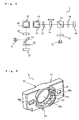
- Fig. 3 is a schematic plan view showing a structure of an optical system of the optical pickup 1 according to the present embodiment. As shown in Fig. 3 , in the optical pickup 1 according to the present embodiment, a route through which laser light emitted form the first light source travels to the first objective 17 is different from a route through which laser light emitted from the second light source 21 travels to the second objective 25.
- Laser light (linearly polarized light) emitted from the first light source 11 is divided by a diffraction device 12 into main light and sub-light. Then, the light is reflected by a polarization beam splitter 13 and passes through a first collimate lens 14.
- the first collimate lens 14 is disposed slidably in an optical-axis direction (a direction indicated by an arrow in Fig. 3 ) to be able to correct spherical aberration. Convergent and divergent states of light entering the first objective 17 is able to be changed by adjusting the position of the first collimate lens 14.
- the laser light having passed through the first collimate lens 14 is transformed by a 1/4 (quarter) wave plate 15 into circularly polarized light, reflected by a first raising mirror 16, and the traveling direction is changed to a direction (a direction from the paper surface toward a point over the paper surface of Fig. 3 ) to the optical disc.
- the light reflected by the first raising mirror 16 is condensed by the first objective 17 on the recording layer of the optical disc.
- the reflected light reflected by the recording layer passes through the first objective 17 and is reflected by the first raising mirror 16 , and transformed by the 1/4 wave plate 15 into linearly polarized light.
- the polarization direction is a direction that is rotated by 90° to the polarization direction of the linearly polarized light emitted from the first light source 11.
- the reflected light having passed the 1/4 wave plate 15 passes through the first collimate lens 14 and the first beam splitter 13, undergoes astigmatism by a first cylindrical lens 18 and is received by a first photo detector 19.
- the first photo detector 19 transduces the received light into an electrical signal and outputs it.
- the outputted electrical signal is processed into a reproduction RF signal, a focus error signal, a tracking error signal or another signal.
- Laser light (linearly polarized light) emitted from the second light source 21 is reflected by a half mirror 22, and transformed by a second collimate lens 23 into parallel light.
- the parallel light transformed by the second collimate lens 23 is reflected by a second raising mirror 24, and its traveling direction is changed to a direction (in Fig. 3 , a direction from the paper surface toward a point over the paper surface) to the optical disc.
- the light reflected by the second raising mirror 24 is condensed by the second objective 25 on the recording layer of the optical disc.
- the reflected light reflected by the recording layer passes through the second objective 25, is reflected by the second collimate lens 23, passes through the half mirror 22, undergoes astigmatism by a second cylindrical lens 26, and received by a second photo detector 27.
- the second photo detector 27 transduces the received light signal into an electrical signal and outputs it.
- the outputted electrical signal is processed into a reproduction RF signal, a focus error signal, a tracking error signal or another signal.
- the first and second objectives 17 and 25 are mounted on the same movable member 4 (see Fig. 2 ) and are able to be moved by an objective actuator 3 (see Fig. 1 or 2 ) in a focusing direction (a direction perpendicular to the paper surface of Fig. 1 ) and in a tracking direction (a direction parallel to the guide shafts 100a and 100b in Fig. 1 ). Focusing adjustment and tracking adjustment are able to be carried out based on the focus error signal and the tracking error signal described above.
- both first and second light sources 11 and 21 are mounted on the main body portion of the optical pickup 1 with held by the light-source holder 5 as shown in Fig. 2 .
- the polarization direction of linearly polarized light emitted from the first light source 11 is different from the polarization direction of linearly polarized light emitted from the second light source 21.
- mount angles of the first and second light sources 11 and 21 to the light-source holder are different from each other, and conventionally it is necessary to prepare two kinds of light-source holders.
- one kind of the light-source holder 5 used in the optical pickup 1 according to the present embodiment is compatible with both first and second light sources 11 and 21 that have different mount angles, and it is unnecessary to prepare two kinds of light-source holders.
- Fig. 4 is a schematic perspective view showing a structure of the light-source holder 5 according to the present embodiment.
- Fig. 5 is a schematic plan view showing a structure of the light-source holder 5 according to the present embodiment.
- Fig. 6 is a schematic plan view seen from a rear side of the light-source holder 5 according to the present embodiment shown in Fig. 5 .
- Fig. 7A is a view to explain a structure of a semiconductor laser device (the first light source 11 or the second light source 21) that is held by the light-source holder 5 according to the present embodiment, that is, a view seen from side of the semiconductor laser device.
- Fig. 7B is a view to explain a structure of a semiconductor laser device (the first light source 11 or the second light source 21) that is held by the light-source holder 5 according to the present embodiment, that is, a view seen from over the semiconductor laser device.
- the light-source holder 5 is used to fix a light source, and is made of a material (e.g., aluminum alloy or the like) that is able to be easily deformed elastically and has good heat radiation.
- the light-source holder 5 has a structure in which a through hole 52 penetrating the holder main body 51 is formed through a substantially central portion of the plate-shape holder main body 51. A semiconductor laser device that serves as the first light source 11 or the second light source 21 is fitted into this through hole 52.
- the semiconductor laser devices that respectively serve as the first light source 11 and the second light source 21 have a structure that comprises a cylinder-shape base 101 on which a chip that emits laser light is fixed, and a cylinder-shape cap 102 that is fixed on the base 101 to cover the chip.
- a ring-shape stopper portion 53 is formed on an inner wall of the through hole 52 of the light-source holder 5.
- the stopper portion 53 is formed on a substantially central portion in the penetration direction of the through hole 52.
- the stopper portion 53 is so formed that the base 101 of the semiconductor laser device comes into contact with the stopper portion 53 when the semiconductor laser device that serves as the first light source 11 or the second light source 21 is fitted into (press-fitted in the present embodiment) the through hole 52.
- the stopper portion 53 has a function (a blocking function) to prevent the semiconductor laser device from coming off the light-source holder 5 when the semiconductor laser device is press-fitted in the through hole 52.
- the light-source holder 5 is so structured that a front side of the light-source holder 5 with respect to the stopper portion 53 functions as a first hold portion 54 to hold a semiconductor laser device that serves as the first light source 11, and an inner side of the light-source holder 5 with respect to the stopper portion 53 functions as a second hold portion 55 to hold a semiconductor laser device that serves as the second light source 21 (see Fig. 4 ).
- Fig. 5 is a schematic plan view of the light-source holder 5 seen from the side of the first hold portion 54
- Fig. 6 is a schematic plan view of the light-source holder 5 seen from the side of the second hold portion 55.
- the first hold portion 54 is provided with first press ribs 56a (first press portions) at three positions that protrude from the inner wall of the through hole 52.
- the surface of this first press rib 56a has a curved surface along part (arc) of a circle presented by a broken line shown in Fig. 5 .
- the three first press ribs 56a are so formed that the diameter of the circle indicated by a broken line in Fig. 5 becomes slightly smaller than the diameter of the base 101 of the semiconductor laser device that serves as the first light source 11. Accordingly, with reference to Fig.
- the first press rib 56a is able to push the base 101 to hold the semiconductor laser device.
- the first hold portion 54 is provided with a first positioning rib 57a (first engagement portion) that protrudes from the inner wall of the through hole 52.
- a groove 103 having a substantially rectangular shape in section is formed on the base 101 of the semiconductor laser device that serves as the first light source 11. This groove 103 is formed to identify, for example, the polarization direction of laser light emitted from the semiconductor laser device.
- the positioning rib 57a that engages with the groove 103 formed on the semiconductor laser device is disposed at a predetermined position of the light-source holder 5, it is possible to dispose the semiconductor laser device in the light-source holder 5 with the polarization direction of laser light (linearly polarized light) emitted from the first light source 11 set to a predetermined direction.
- the first positioning rib 57a is formed for this intention.
- the second hold portion 55 also is provided with second press ribs 56b (second press portions) at three positions that protrude from the inner wall of the through hole 52.
- second press ribs 56b second press portions
- a second positioning rib 57b second engagement portion that protrudes from the inner wall of the through hole 52 is formed.
- the positions of the press ribs of the first hold portion 54 and the second hold portion 55 are different from each other, and the positions of the positioning ribs of the first hold portion 54 and the second hold portion 55 are different from each other.
- the second press ribs 56b and the second positioning rib 57b are formed at positions respectively rotated by an angle of ⁇ to the positions where the first press ribs 56a and the first positioning rib 57a are formed. This is because in the optical pickup 1 according to the present embodiment, it is necessary to shift the polarization directions of laser light emitted from the first light source 11 and from the second light source by the angle of ⁇ from each other.
- the light-source holder 5 is so structured as in the present embodiment, effects are obtained as follows.
- the semiconductor laser device is pres-fitted into the thorough hole 52 with the base 101 disposed at a position away from the paper surface and the cap 102 disposed at a position closer to the paper surface, it is possible to dispose the light-source holder 5 that holds the semiconductor laser device at a desired mount angle in the optical pickup 1.
- the semiconductor laser device when using the light-source holder 5 for the second light source 11, if the semiconductor laser device is pres-fitted into the thorough hole 52 with the cap 102 disposed at a position away from the paper surface and the base 101 disposed at a position closer to the paper surface, it is possible to dispose the light-source holder 5 that holds the semiconductor laser device at a desired mount angle in the optical pickup 1.
- the cap 102 when press-fitting the semiconductor laser device into the through hole 52, the cap 102 is first inserted and then the base 101 is.
- holes 58a and 58b that penetrate the holder main body 51 are formed interposing the through hole 5 therebetween, that is, one on each side.
- the holes 58a and 58b are jig holes that allow the light-source holder 5 to be held with jigs and also optical-axis alignment of the first and second light sources 11 and 21 to be performed.
- one of the jig holes 58a and 58b is formed oblong.
- the jig holes 58a and 58b are so formed to be through holes, even if the light-source holder 5 is used for any one of the first light source 11 and the second light source 21, it is possible to perform optical-axis alignment of the light source.
- first press ribs 56a and second press ribs 56b are each three.
- the numbers are not limited to three, and can be changed suitably.
- the shapes of the press ribs 56 and 56b also are not limited to those in the present embodiments, and other shapes may be used if a semiconductor laser device can be held by press-fitting the semiconductor laser device into the through hole 52.
- the numbers of first positioning ribs 57a and second positioning ribs 57b are each one.
- the numbers are not limited to one, and may be changed suitably for a structure of a semiconductor laser device.
- the shapes of the positioning ribs 57a and 57b may be changed suitably for a shape of the groove 103 formed on a semiconductor laser device.
- the light-source holder 5 is used for the first and second light sources that have the same shape.
- the shapes of the first and second light sources 11 and 21 can be different from each other (also different in size).
- the light-source holder according to the present invention is applicable to such a case.
- shapes of the parts to hold a light source need only to be different for a shape of the light source.
- the first light source 11 is a semiconductor laser device for a BD
- the second light source 21 is a semiconductor laser device for a DVD and a CD.
- the present invention is not limited to this structure, and it is needless to say that the present invention is widely applicable to optical pickups that use a plurality of light sources.
- the light-source holder according to the present invention is preferably applicable to optical pickups that comprise two light sources.
- the light source holders described above have a multitude of features provided in special combinations. The skilled person will consider theses features and the advantages thereof also individually and in further sub-combinations in order to adapt the light source holder according to the invention to his specific needs.
Landscapes
- Physics & Mathematics (AREA)
- Optics & Photonics (AREA)
- Optical Head (AREA)
Abstract
Description
- The present invention relates to a light-source holder that is used to hold a light source disposed in an optical pickup, and also relates to an optical pickup having the light-source holder.
- Optical recording media such as compact discs (hereinafter, referred to as CD), digital versatile discs (hereinafter, referred to as DVD) etc. have been widely used. Further, in recent years, optical recording media such as Blu-ray discs (hereinafter, called BD) and the like that can record large-size information have also been put to practical use. To carry out reading and writing of information from and to such an optical recording medium, an optical pickup is used.
- In an optical pickup, for example, to carry out reading and writing of information from and to a CD, light having a wavelength of, for example, 780 nm is used. For a DVD, light having a wavelength of, for example, 650 nm is used, and for a BD, light having a wavelength of, for example, 405 nm is used. Accordingly, in some conventional optical pickups, a plurality of light sources which emit light having respective wavelengths different from each other are used.
- In an optical pickup, conventionally, a semiconductor laser device is used as a light source that is used to direct light to an optical recoding medium. Such a semiconductor laser device is generally mounted on an optical pickup with held by a holder (e.g, see
patent documents 1 to 3). And, if a plurality of semiconductor laser devices are used to carry out reading and writing of information from and to a plurality kinds of optical recording media, the semiconductor laser devices need respective holders. - Laser light emitted from a semiconductor laser device used in an optical pickup is generally linearly polarized light. And, in some optical pickups that comprise a plurality of semiconductor laser devices, polarization directions of laser light (linearly polarized light) emitted from the respective semiconductor laser devices are different from each other. In such a case, because mount directions (mount angles) in which the semiconductor laser devices are mounted on a holder are different from each other, it is necessary to use different-structure holders for the respective semiconductor laser devices. Accordingly, it is necessary to prepare different molds for the different-structure holders and make the holders separately, which causes increase in production cost of the pickups.
[patent document 1]JP No. 3779608
[patent document 2]JP No. 3833934
[patent document 3]JP-A-2004-111507 - The present invention has been made to cope with the conventional problems, and it is an object of the present invention to provide a light-source holder that is low in cost even if it is required to hold a plurality of light sources which an optical pickup includes. And, it is another object of the present invention to provide an optical pickup that includes a light-source holder according the present invention and is able to be produced at low cost even if the optical pickup comprises a plurality of light sources.
- To achieve the object, the invention proposes a light-source holder used to hold a light source disposed in an optical pickup according to
claim 1, which may comprise: a holder main body portion; a through hole which penetrates the holder main body portion and in which a light source is fitted; a first hold potion that holds a first light source if the first light source is fitted in the through hole from a first side, one of first and second sides of the holder main body portion which are opposite to each other with respect to the holder main body portion; and a second hold portion that holds a second light source if the second light source is fitted in the through hole from a second side, one of the first and second sides of the holder main body portion which are opposite to each other with respect to the holder main body portion. - According to this structure, it is possible to fit two different light sources in the light-source holder from the different sides. Accordingly, even if a plurality of light sources are needed for an optical pickup, the number of light-source holders to be prepared is able to be reduced. And, for example, even if an optical pickup requires two light sources, a kind of light-source holder needs only to be prepared. Accordingly, it is possible to curb production cost of the pickup.
- The above light-source holder may have the following structure as a specific structure, in which a ring-shape stopper portion protruding from an inner wall of the through hole is formed at a substantially central portion in a penetration direction of the through hole, the first and second hold portions are formed at positions which are opposite to each other with respect to the stopper portion, the first hold portion is provided with a first press portion which protrudes from the inner wall of the through hole and presses part of the first light source fitted in from the first side, and the second hold portion is provided with a second press portion which protrudes from the inner wall of the through hole and presses part of the second light source fitted in from the second side.
- According to this structure, if the first light source or the second light source is press-fitted in the through hole, the stopper portion functions as a lock member for the light source. Accordingly, even if any one of the first and second light sources is mounted, it is possible to stably hold the light source.
- In the light-source holder having the above structure, a structure may be employed, in which a groove portion is formed on the first and second light sources, the first holder portion is equipped with a first engagement portion that protrudes from the inner wall of the through hole and engages with the groove portion of the first light source, the second holder portion is equipped with a second engagement portion that protrudes from the inner wall of the through hole and engages with the groove portion of the second light source. In this structure, directions in which the first and second engagement portions protrude from the inner wall of the through hole may be different form each other.
- In some cases where two light sources are incorporated in an optical pickup, polarization directions of linearly polarized light emitted from the light sources are different from each other. In such cases, mount directions of the light sources are different from each other. In this respect, according to this structure, it is possible to control the mount directions of the light sources according to the protrusion directions of the engagement portions. And, even if the mount directions of the two light sources are different from each other, it is unnecessary to prepare two light-source holders, which is able to curb production cost.
- In the light-source holder having the above structure, a structure may be employed, in which jig holes are so formed through the holder main body portion as to be opposite to each other with respect to the through hole, penetrate the holder main body portion in the same direction as the through hole, and allow the holder main body portion to be held with jigs. According to this structure, because the jig holes are through holes, it is possible to easily carry out optical-axis alignment of the light source using jigs even if any one of the first and second light sources is mounted on the light-source holder.
- Besides, to achieve the above object, an optical pickup according to the present invention comprises: the light-source holder having the above structure; the first light source; and the second light source. According to this structure, despite the two light sources being employed, because only one kind of light-source holder needs to be prepared to fabricate an optical pickup, it is possible to curb the production cost.
- The above optical pickup may have the following structure as a specific structure, in which the first light source is a semiconductor laser device that emits laser light for a BD, and the second light source is a semiconductor laser device that emits laser light switching for a DVD and a CD.
- According the present invention, even if the optical pickup comprises a plurality of light sources, it is possible to curb the cost required for the light-source holder that holds the light sources.
-
-
Fig. 1 is a schematic plan view showing a structure of an optical pickup according to an embodiment. -
Fig. 2 is a schematic side view showing an optical pickup according to the present embodiment, that is, a side view seen from a position-A side inFig. 1 . -
Fig. 3 is a schematic plan view showing an optical system of an optical pickup according to the present embodiment. -
Fig. 4 is a schematic perspective view showing a structure of a light-source holder according to an embodiment. -
Fig. 5 is a schematic plan view showing a structure of a light-source holder according to the present embodiment. -
Fig. 6 is a schematic plan view seen from a rear side of the light-source holder according to the present embodiment shown inFig. 5 . -
Fig. 7A is a view to explain a structure of a semiconductor laser device that is held in a light-source holder according to the present embodiment, that is, a view seen from side of the semiconductor laser device. - Fig. 7B is a view to explain a structure of a semiconductor laser device that is held in a light-source holder according to the present embodiment, that is, a view seen from over the semiconductor laser device.
- Hereinafter, present embodiments of a light-source holder and an optical pickup according to the present invention are explained with reference to drawings.
- Optical-Pickup Structure: First, a structure of an optical pickup according to an embodiment is explained.
Fig. 1 is a schematic plan view showing a structure of an optical pickup according to the present embodiment.Fig. 2 is a schematic side view showing an optical pickup according to the present embodiment, that is, a side view seen from a position-A side inFig. 1 . InFig. 1 , for explanation convenience,guide shafts - An
optical pickup 1 directs laser light to an optical disc, not shown, (with reference toFig. 1 , disposed at a position over the paper surface ofFig. 1 ), receives reflected light reflected by the optical disc, transduces optical signals into electrical signals and outputs them. As shown inFig. 1 , generally, theoptical pickup 1 is disposed movably along the twoguide shafts optical pickup 1 is able to access each address formed on the optical disc that rotates at high speed, and it is possible to carry out reading and writing of information from and to the optical disc. - As shown in
Fig. 1 , theoptical pickup 1 is equipped with guide-shaft support portions 2a and 2b that allow theoptical pickup 1 to be slidably mounted on the twoguide shafts Figs. 1 and 2 , theoptical pickup 1 comprises afirst light source 11, asecond light source 21, a first objective lens (objective) 17, and asecond objective 25. Light emitted from thefirst light source 11 is condensed on a recording layer of the optical disc by thefirst objective 17. Laser light emitted from the secondlight source 21 is condensed on the recording layer of the optical disc by thesecond objective 25. - The
optical pickup 1 according to the present embodiment is so disposed that theoptical pickup 1 is able to perform reading and writing of information from and to three kinds of optical discs, BD, DVD and CD. Thefirst light source 11 is a semiconductor laser device for a BD that emits laser light having a wavelength of, for example, 405 nm. The secondlight source 21 is a semiconductor laser device (two-wavelength laser) for a DVD and a CD that is able to emit, for example, laser light having a wavelength of 650 nm and laser light having a wavelength of 780 nm switching them. As the two-wavelength laser, what is called a monolithic semiconductor laser device or a hybrid semiconductor laser device is preferably used. Laser light emitted from the first and secondlight sources -
Fig. 3 is a schematic plan view showing a structure of an optical system of theoptical pickup 1 according to the present embodiment. As shown inFig. 3 , in theoptical pickup 1 according to the present embodiment, a route through which laser light emitted form the first light source travels to thefirst objective 17 is different from a route through which laser light emitted from the secondlight source 21 travels to thesecond objective 25. - Laser light (linearly polarized light) emitted from the
first light source 11 is divided by adiffraction device 12 into main light and sub-light. Then, the light is reflected by apolarization beam splitter 13 and passes through afirst collimate lens 14. Thefirst collimate lens 14 is disposed slidably in an optical-axis direction (a direction indicated by an arrow inFig. 3 ) to be able to correct spherical aberration. Convergent and divergent states of light entering thefirst objective 17 is able to be changed by adjusting the position of thefirst collimate lens 14. - The laser light having passed through the
first collimate lens 14 is transformed by a 1/4 (quarter)wave plate 15 into circularly polarized light, reflected by afirst raising mirror 16, and the traveling direction is changed to a direction (a direction from the paper surface toward a point over the paper surface ofFig. 3 ) to the optical disc. The light reflected by thefirst raising mirror 16 is condensed by the first objective 17 on the recording layer of the optical disc. - Then, the reflected light reflected by the recording layer passes through the
first objective 17 and is reflected by thefirst raising mirror 16 , and transformed by the 1/4wave plate 15 into linearly polarized light. Here, the polarization direction is a direction that is rotated by 90° to the polarization direction of the linearly polarized light emitted from thefirst light source 11. - The reflected light having passed the 1/4
wave plate 15 passes through thefirst collimate lens 14 and thefirst beam splitter 13, undergoes astigmatism by a firstcylindrical lens 18 and is received by afirst photo detector 19. Thefirst photo detector 19 transduces the received light into an electrical signal and outputs it. The outputted electrical signal is processed into a reproduction RF signal, a focus error signal, a tracking error signal or another signal. - Laser light (linearly polarized light) emitted from the second
light source 21 is reflected by ahalf mirror 22, and transformed by asecond collimate lens 23 into parallel light. The parallel light transformed by thesecond collimate lens 23 is reflected by asecond raising mirror 24, and its traveling direction is changed to a direction (inFig. 3 , a direction from the paper surface toward a point over the paper surface) to the optical disc. The light reflected by thesecond raising mirror 24 is condensed by thesecond objective 25 on the recording layer of the optical disc. - Then, the reflected light reflected by the recording layer passes through the
second objective 25, is reflected by thesecond collimate lens 23, passes through thehalf mirror 22, undergoes astigmatism by a secondcylindrical lens 26, and received by asecond photo detector 27. Thesecond photo detector 27 transduces the received light signal into an electrical signal and outputs it. The outputted electrical signal is processed into a reproduction RF signal, a focus error signal, a tracking error signal or another signal. - The first and
second objectives Fig. 2 ) and are able to be moved by an objective actuator 3 (seeFig. 1 or 2 ) in a focusing direction (a direction perpendicular to the paper surface ofFig. 1 ) and in a tracking direction (a direction parallel to theguide shafts Fig. 1 ). Focusing adjustment and tracking adjustment are able to be carried out based on the focus error signal and the tracking error signal described above. - In the
optical pickup 1 having the structure according to the present embodiment described above, both first and secondlight sources optical pickup 1 with held by the light-source holder 5 as shown inFig. 2 . In theoptical pickup 1 according to the present embodiment, the polarization direction of linearly polarized light emitted from thefirst light source 11 is different from the polarization direction of linearly polarized light emitted from the secondlight source 21. Accordingly, mount angles of the first and secondlight sources source holder 5 used in theoptical pickup 1 according to the present embodiment is compatible with both first and secondlight sources - Light-Source Holder Structure: Hereinafter, a structure of the light-
source holder 5 according to the present embodiment is explained.Fig. 4 is a schematic perspective view showing a structure of the light-source holder 5 according to the present embodiment.Fig. 5 is a schematic plan view showing a structure of the light-source holder 5 according to the present embodiment.Fig. 6 is a schematic plan view seen from a rear side of the light-source holder 5 according to the present embodiment shown inFig. 5 .Fig. 7A is a view to explain a structure of a semiconductor laser device (thefirst light source 11 or the second light source 21) that is held by the light-source holder 5 according to the present embodiment, that is, a view seen from side of the semiconductor laser device. Fig. 7B is a view to explain a structure of a semiconductor laser device (thefirst light source 11 or the second light source 21) that is held by the light-source holder 5 according to the present embodiment, that is, a view seen from over the semiconductor laser device. - The light-
source holder 5 is used to fix a light source, and is made of a material (e.g., aluminum alloy or the like) that is able to be easily deformed elastically and has good heat radiation. The light-source holder 5 has a structure in which a throughhole 52 penetrating the holdermain body 51 is formed through a substantially central portion of the plate-shape holdermain body 51. A semiconductor laser device that serves as thefirst light source 11 or the secondlight source 21 is fitted into this throughhole 52. - As shown in
Figs. 7A and 7B, the semiconductor laser devices that respectively serve as thefirst light source 11 and the secondlight source 21 have a structure that comprises a cylinder-shape base 101 on which a chip that emits laser light is fixed, and a cylinder-shape cap 102 that is fixed on the base 101 to cover the chip. - As shown in
Fig. 4 , a ring-shape stopper portion 53 is formed on an inner wall of the throughhole 52 of the light-source holder 5. Thestopper portion 53 is formed on a substantially central portion in the penetration direction of the throughhole 52. Besides, thestopper portion 53 is so formed that thebase 101 of the semiconductor laser device comes into contact with thestopper portion 53 when the semiconductor laser device that serves as thefirst light source 11 or the secondlight source 21 is fitted into (press-fitted in the present embodiment) the throughhole 52. In other words, thestopper portion 53 has a function (a blocking function) to prevent the semiconductor laser device from coming off the light-source holder 5 when the semiconductor laser device is press-fitted in the throughhole 52. - The light-
source holder 5 according to the present embodiment is so structured that a front side of the light-source holder 5 with respect to thestopper portion 53 functions as afirst hold portion 54 to hold a semiconductor laser device that serves as thefirst light source 11, and an inner side of the light-source holder 5 with respect to thestopper portion 53 functions as asecond hold portion 55 to hold a semiconductor laser device that serves as the second light source 21 (seeFig. 4 ). In this respect,Fig. 5 is a schematic plan view of the light-source holder 5 seen from the side of thefirst hold portion 54, andFig. 6 is a schematic plan view of the light-source holder 5 seen from the side of thesecond hold portion 55. - As shown in
Fig. 5 , thefirst hold portion 54 is provided withfirst press ribs 56a (first press portions) at three positions that protrude from the inner wall of the throughhole 52. The surface of thisfirst press rib 56a has a curved surface along part (arc) of a circle presented by a broken line shown inFig. 5 . Besides, the threefirst press ribs 56a are so formed that the diameter of the circle indicated by a broken line inFig. 5 becomes slightly smaller than the diameter of thebase 101 of the semiconductor laser device that serves as thefirst light source 11. Accordingly, with reference toFig. 5 , if the semiconductor laser device is press-fitted into the throughhole 52 with the base 101 disposed at a position away from the paper surface and thecap 102 disposed at a position closer to the paper surface in the direction from a point away from the paper surface to a point closer to the paper surface, thefirst press rib 56a is able to push thebase 101 to hold the semiconductor laser device. - As shown in
Fig. 5 , thefirst hold portion 54 is provided with afirst positioning rib 57a (first engagement portion) that protrudes from the inner wall of the throughhole 52. As shown inFigs. 7A and 7B, agroove 103 having a substantially rectangular shape in section is formed on thebase 101 of the semiconductor laser device that serves as thefirst light source 11. Thisgroove 103 is formed to identify, for example, the polarization direction of laser light emitted from the semiconductor laser device. Accordingly, if thepositioning rib 57a that engages with thegroove 103 formed on the semiconductor laser device is disposed at a predetermined position of the light-source holder 5, it is possible to dispose the semiconductor laser device in the light-source holder 5 with the polarization direction of laser light (linearly polarized light) emitted from thefirst light source 11 set to a predetermined direction. Thefirst positioning rib 57a is formed for this intention. - As shown in
Fig. 6 , like thefirst hold portion 54, thesecond hold portion 55 also is provided withsecond press ribs 56b (second press portions) at three positions that protrude from the inner wall of the throughhole 52. Besides, like thefirst positioning rib 57a of thefirst hold portion 54, asecond positioning rib 57b (second engagement portion) that protrudes from the inner wall of the throughhole 52 is formed. However, the positions of the press ribs of thefirst hold portion 54 and thesecond hold portion 55 are different from each other, and the positions of the positioning ribs of thefirst hold portion 54 and thesecond hold portion 55 are different from each other. - In other words, the
second press ribs 56b and thesecond positioning rib 57b are formed at positions respectively rotated by an angle of α to the positions where thefirst press ribs 56a and thefirst positioning rib 57a are formed. This is because in theoptical pickup 1 according to the present embodiment, it is necessary to shift the polarization directions of laser light emitted from thefirst light source 11 and from the second light source by the angle of α from each other. - Because the light-
source holder 5 is so structured as in the present embodiment, effects are obtained as follows. In other words, with reference toFig. 4 , when using the light-source holder 5 for thefirst light source 11, if the semiconductor laser device is pres-fitted into thethorough hole 52 with the base 101 disposed at a position away from the paper surface and thecap 102 disposed at a position closer to the paper surface, it is possible to dispose the light-source holder 5 that holds the semiconductor laser device at a desired mount angle in theoptical pickup 1. Besides, with reference toFig 4 , when using the light-source holder 5 for the secondlight source 11, if the semiconductor laser device is pres-fitted into thethorough hole 52 with thecap 102 disposed at a position away from the paper surface and the base 101 disposed at a position closer to the paper surface, it is possible to dispose the light-source holder 5 that holds the semiconductor laser device at a desired mount angle in theoptical pickup 1. Here, when press-fitting the semiconductor laser device into the throughhole 52, thecap 102 is first inserted and then thebase 101 is. - In the light-
source holder 5 according to the present embodiment, as shown inFigs. 4 to 6 ,holes main body 51 are formed interposing the throughhole 5 therebetween, that is, one on each side. Theholes source holder 5 to be held with jigs and also optical-axis alignment of the first and secondlight sources source holder 5 and jigs, one of the jig holes 58a and 58b is formed oblong. And, because the jig holes 58a and 58b are so formed to be through holes, even if the light-source holder 5 is used for any one of thefirst light source 11 and the secondlight source 21, it is possible to perform optical-axis alignment of the light source. - Others: The present embodiments explained above are examples, the present invention is not limited to the present embodiments and various modifications are possible without departing the objects of the present invention.
- For example, in the present embodiments, the numbers of
first press ribs 56a andsecond press ribs 56b are each three. However, the numbers are not limited to three, and can be changed suitably. Besides, the shapes of thepress ribs 56 and 56b also are not limited to those in the present embodiments, and other shapes may be used if a semiconductor laser device can be held by press-fitting the semiconductor laser device into the throughhole 52. - In the present embodiments, the numbers of
first positioning ribs 57a andsecond positioning ribs 57b are each one. However, the numbers are not limited to one, and may be changed suitably for a structure of a semiconductor laser device. Besides, the shapes of thepositioning ribs groove 103 formed on a semiconductor laser device. - In the present embodiments, the light-
source holder 5 is used for the first and second light sources that have the same shape. However, the shapes of the first and secondlight sources second hold portions - In the present embodiments, the
first light source 11 is a semiconductor laser device for a BD, and the secondlight source 21 is a semiconductor laser device for a DVD and a CD. However, the present invention is not limited to this structure, and it is needless to say that the present invention is widely applicable to optical pickups that use a plurality of light sources. - The light-source holder according to the present invention is preferably applicable to optical pickups that comprise two light sources.
The light source holders described above have a multitude of features provided in special combinations. The skilled person will consider theses features and the advantages thereof also individually and in further sub-combinations in order to adapt the light source holder according to the invention to his specific needs.
Claims (7)
- A light-source holder used to hold a light source disposed in an optical pickup (1), comprising:a holder main body portion (51);a through hole (52) which penetrates the holder main body portion (51) and in which a light source (11, 21) is fitted;a first hold potion (54) that holds a first light source (11) if the first light source (11) is fitted in the through hole (52) from a first side, one of first and second sides of the holder main body portion (51) which are opposite to each other with respect to the holder main body portion (51);and a second hold portion (55) that holds a second light source (21) if the second light source (21) is fitted in the through hole (52) from a second side, one of the first and second sides of the holder main body portion (51)which are opposite to each other with respect to the holder main body portion (51).
- The light-source holder according to claim 1, whereina ring-shape stopper portion (53) protruding from an inner wall of the through hole (52) is formed at a substantially central portion in a penetration direction of the through hole (52),the first and second hold portions (54, 55) are formed at positions which are opposite to each other with respect to the stopper portion (53),the first hold portion (54) is provided with a first press portion (56a) which protrudes from the inner wall of the through hole (52) and presses part of the first light source (11) fitted in from the first side, andthe second hold portion (55) is provided with a second press portion (56b) which protrudes from the inner wall of the through hole (52) and presses part of the second light source (21) fitted in from the second side.
- The light-source holder according to claim 1 or 2, whereina groove portion (103) is formed on the first and second light sources (11, 21),the first holder portion (54) is equipped with a first engagement (57a) portion that protrudes from the inner wall of the through hole (52) and engages with the groove portion (103) of the first light source (11), andthe second holder portion (55) is equipped with a second engagement portion (57b) that protrudes from the inner wall of the through hole (52) and engages with the groove portion (103) of the second light source (21).
- The light-source holder according to claim 3, wherein directions in which the first and second engagement portions (57a, 57b( protrude from the inner wall of the through hole (52) are different form each other.
- The light-source holder according any one claims 1 to 4, wherein jig holes (58a, 58b) are so formed through the holder main body portion (51) as to be opposite to each other with respect to the through hole (52), penetrate the holder main body portion (51) in the same direction as the through hole (52), and allow the holder main body portion (51) to be held with jigs.
- An optical pickup, comprising the light-source holder according to any one of claims 1 to 5, the first light source (11), and the second light source (21).
- The optical pickup according to claim 6, wherein the first light source (11) is a semiconductor laser device that emits laser light for a BD, and the second light source (21) is a semiconductor laser device that emits laser light switching for a DVD and a CD.
Applications Claiming Priority (1)
| Application Number | Priority Date | Filing Date | Title |
|---|---|---|---|
| JP2008096947A JP4609517B2 (en) | 2008-04-03 | 2008-04-03 | Light source holder and optical pickup including the same |
Publications (2)
| Publication Number | Publication Date |
|---|---|
| EP2107563A1 true EP2107563A1 (en) | 2009-10-07 |
| EP2107563B1 EP2107563B1 (en) | 2011-11-16 |
Family
ID=40756956
Family Applications (1)
| Application Number | Title | Priority Date | Filing Date |
|---|---|---|---|
| EP09004750A Not-in-force EP2107563B1 (en) | 2008-04-03 | 2009-03-31 | Light-source holder and optical pickup having same |
Country Status (3)
| Country | Link |
|---|---|
| US (1) | US8141110B2 (en) |
| EP (1) | EP2107563B1 (en) |
| JP (1) | JP4609517B2 (en) |
Families Citing this family (2)
| Publication number | Priority date | Publication date | Assignee | Title |
|---|---|---|---|---|
| JP2012160219A (en) * | 2011-01-28 | 2012-08-23 | Funai Electric Co Ltd | Laser holder and optical pickup with the same |
| TWI706179B (en) * | 2018-10-01 | 2020-10-01 | 創威光電股份有限公司 | Optical sub-assembly module and cap of optical sub-assembly module |
Citations (7)
| Publication number | Priority date | Publication date | Assignee | Title |
|---|---|---|---|---|
| JP2003187478A (en) * | 2001-12-20 | 2003-07-04 | Sankyo Seiki Mfg Co Ltd | Optical head device |
| JP2003217134A (en) * | 2002-01-22 | 2003-07-31 | Mitsumi Electric Co Ltd | Optical pickup device |
| EP1381040A2 (en) * | 2002-07-01 | 2004-01-14 | Mitsumi Electric Co., Ltd. | Optical pickup having optical base made of different kinds of materials |
| JP2004111507A (en) | 2002-09-17 | 2004-04-08 | Sanyo Electric Co Ltd | Semiconductor laser fixing apparatus |
| US20050086677A1 (en) * | 2003-10-21 | 2005-04-21 | Hitachi, Ltd. | Optical pickup apparatus |
| JP3833934B2 (en) | 2001-12-20 | 2006-10-18 | 日本電産サンキョー株式会社 | Optical head device |
| US20070115615A1 (en) * | 2005-11-18 | 2007-05-24 | Funai Electric Co., Ltd. | Optical head |
Family Cites Families (8)
| Publication number | Priority date | Publication date | Assignee | Title |
|---|---|---|---|---|
| JPS6090854A (en) | 1983-10-21 | 1985-05-22 | Furukawa Electric Co Ltd:The | Method for coating optical fiber |
| JPS6090854U (en) * | 1983-11-26 | 1985-06-21 | 三洋電機株式会社 | Light emitting element mounting device |
| JPH0636324A (en) * | 1992-07-17 | 1994-02-10 | Ricoh Co Ltd | Optical disk device |
| JPH0963064A (en) * | 1995-08-28 | 1997-03-07 | Toshiba Corp | Optical disc device, optical axis adjusting device for optical disc device, and optical axis adjusting method for optical disc device |
| JP2001116957A (en) * | 1999-10-21 | 2001-04-27 | Minolta Co Ltd | Optical module and light source unit |
| JP3841217B2 (en) * | 2003-06-17 | 2006-11-01 | 船井電機株式会社 | Optical pickup |
| JP2005108300A (en) * | 2003-09-29 | 2005-04-21 | Toshiba Corp | Optical pickup device |
| US20090055851A1 (en) * | 2005-04-28 | 2009-02-26 | Toshiyasu Tanaka | Optical pickup device, optical information device provided with such optical pickup device, and optical information recording/reproducing device provided with such optical information device |
-
2008
- 2008-04-03 JP JP2008096947A patent/JP4609517B2/en not_active Expired - Fee Related
-
2009
- 2009-03-31 US US12/415,453 patent/US8141110B2/en not_active Expired - Fee Related
- 2009-03-31 EP EP09004750A patent/EP2107563B1/en not_active Not-in-force
Patent Citations (8)
| Publication number | Priority date | Publication date | Assignee | Title |
|---|---|---|---|---|
| JP2003187478A (en) * | 2001-12-20 | 2003-07-04 | Sankyo Seiki Mfg Co Ltd | Optical head device |
| JP3779608B2 (en) | 2001-12-20 | 2006-05-31 | 日本電産サンキョー株式会社 | Optical head device |
| JP3833934B2 (en) | 2001-12-20 | 2006-10-18 | 日本電産サンキョー株式会社 | Optical head device |
| JP2003217134A (en) * | 2002-01-22 | 2003-07-31 | Mitsumi Electric Co Ltd | Optical pickup device |
| EP1381040A2 (en) * | 2002-07-01 | 2004-01-14 | Mitsumi Electric Co., Ltd. | Optical pickup having optical base made of different kinds of materials |
| JP2004111507A (en) | 2002-09-17 | 2004-04-08 | Sanyo Electric Co Ltd | Semiconductor laser fixing apparatus |
| US20050086677A1 (en) * | 2003-10-21 | 2005-04-21 | Hitachi, Ltd. | Optical pickup apparatus |
| US20070115615A1 (en) * | 2005-11-18 | 2007-05-24 | Funai Electric Co., Ltd. | Optical head |
Also Published As
| Publication number | Publication date |
|---|---|
| JP4609517B2 (en) | 2011-01-12 |
| US8141110B2 (en) | 2012-03-20 |
| JP2009252272A (en) | 2009-10-29 |
| US20090284971A1 (en) | 2009-11-19 |
| EP2107563B1 (en) | 2011-11-16 |
Similar Documents
| Publication | Publication Date | Title |
|---|---|---|
| CN100358022C (en) | Optical pickup, apparatus and method for assembling lens | |
| US20020093744A1 (en) | Optical pickup apparatus and read/write apparatus | |
| US7787340B2 (en) | Optical pickup | |
| EP2107563B1 (en) | Light-source holder and optical pickup having same | |
| JP4744631B2 (en) | Lens fixing device and optical pickup device | |
| US6115349A (en) | Two laser source optical pickup with a plano-convex lens to compensate for aberration caused by discs of different thicknesses | |
| US20090201789A1 (en) | Optical head device for forming light spot on disc-shaped information medium | |
| EP2207176B1 (en) | Optical pickup | |
| EP1096482A2 (en) | Optical pickup for cd/dvd compatible player | |
| US6707615B2 (en) | Optical pickup apparatus restricting aberration and optical disc apparatus using the same | |
| EP1761921B1 (en) | Apparatus and method for generating a scanning beam in an optical pickup head, miniature optical pickup head and optical storage system incorporating a miniature pickup head | |
| US7839754B2 (en) | Optical head and optical disk device | |
| US20040027970A1 (en) | Optical pickup and optical recording and/or reproducing apparatus using the same | |
| JP2000020982A (en) | Two-lens optical head device and disk recording or reproducing device | |
| US20060104166A1 (en) | Combination of lens and lens holder and optical pickup unit having the same | |
| JPWO2008099622A1 (en) | Optical pickup device | |
| JP2005203004A (en) | Optical head | |
| JP2002074684A (en) | Optical head device | |
| JP2009252327A (en) | Optical pickup apparatus | |
| JP2015109117A (en) | Optical pickup device | |
| JP2007293956A (en) | Optical pickup and optical disc apparatus | |
| JP2008192203A (en) | Lens actuator, optical pickup device, and optical recording / reproducing device | |
| JP2006073156A (en) | Optical pickup and disk drive device | |
| JP2010165436A (en) | Optical pickup | |
| JP2013254535A (en) | Optical pickup device, optical pickup adjustment method, and optical disk unit |
Legal Events
| Date | Code | Title | Description |
|---|---|---|---|
| PUAI | Public reference made under article 153(3) epc to a published international application that has entered the european phase |
Free format text: ORIGINAL CODE: 0009012 |
|
| AK | Designated contracting states |
Kind code of ref document: A1 Designated state(s): AT BE BG CH CY CZ DE DK EE ES FI FR GB GR HR HU IE IS IT LI LT LU LV MC MK MT NL NO PL PT RO SE SI SK TR |
|
| AX | Request for extension of the european patent |
Extension state: AL BA RS |
|
| 17P | Request for examination filed |
Effective date: 20100318 |
|
| AKX | Designation fees paid |
Designated state(s): DE FR GB |
|
| 17Q | First examination report despatched |
Effective date: 20110113 |
|
| GRAP | Despatch of communication of intention to grant a patent |
Free format text: ORIGINAL CODE: EPIDOSNIGR1 |
|
| GRAS | Grant fee paid |
Free format text: ORIGINAL CODE: EPIDOSNIGR3 |
|
| GRAA | (expected) grant |
Free format text: ORIGINAL CODE: 0009210 |
|
| AK | Designated contracting states |
Kind code of ref document: B1 Designated state(s): DE FR GB |
|
| REG | Reference to a national code |
Ref country code: GB Ref legal event code: FG4D |
|
| REG | Reference to a national code |
Ref country code: DE Ref legal event code: R096 Ref document number: 602009003660 Country of ref document: DE Effective date: 20120112 |
|
| PLBE | No opposition filed within time limit |
Free format text: ORIGINAL CODE: 0009261 |
|
| STAA | Information on the status of an ep patent application or granted ep patent |
Free format text: STATUS: NO OPPOSITION FILED WITHIN TIME LIMIT |
|
| 26N | No opposition filed |
Effective date: 20120817 |
|
| REG | Reference to a national code |
Ref country code: DE Ref legal event code: R097 Ref document number: 602009003660 Country of ref document: DE Effective date: 20120817 |
|
| PGFP | Annual fee paid to national office [announced via postgrant information from national office to epo] |
Ref country code: FR Payment date: 20140311 Year of fee payment: 6 |
|
| PGFP | Annual fee paid to national office [announced via postgrant information from national office to epo] |
Ref country code: GB Payment date: 20140326 Year of fee payment: 6 |
|
| PGFP | Annual fee paid to national office [announced via postgrant information from national office to epo] |
Ref country code: DE Payment date: 20140417 Year of fee payment: 6 |
|
| REG | Reference to a national code |
Ref country code: DE Ref legal event code: R119 Ref document number: 602009003660 Country of ref document: DE |
|
| GBPC | Gb: european patent ceased through non-payment of renewal fee |
Effective date: 20150331 |
|
| REG | Reference to a national code |
Ref country code: FR Ref legal event code: ST Effective date: 20151130 |
|
| PG25 | Lapsed in a contracting state [announced via postgrant information from national office to epo] |
Ref country code: GB Free format text: LAPSE BECAUSE OF NON-PAYMENT OF DUE FEES Effective date: 20150331 Ref country code: DE Free format text: LAPSE BECAUSE OF NON-PAYMENT OF DUE FEES Effective date: 20151001 |
|
| PG25 | Lapsed in a contracting state [announced via postgrant information from national office to epo] |
Ref country code: FR Free format text: LAPSE BECAUSE OF NON-PAYMENT OF DUE FEES Effective date: 20150331 |