EP2107417A1 - Design method of aspheric ophthalmic lens - Google Patents
Design method of aspheric ophthalmic lens Download PDFInfo
- Publication number
- EP2107417A1 EP2107417A1 EP20090156602 EP09156602A EP2107417A1 EP 2107417 A1 EP2107417 A1 EP 2107417A1 EP 20090156602 EP20090156602 EP 20090156602 EP 09156602 A EP09156602 A EP 09156602A EP 2107417 A1 EP2107417 A1 EP 2107417A1
- Authority
- EP
- European Patent Office
- Prior art keywords
- ophthalmic lens
- optical system
- designing
- eye
- aberration
- Prior art date
- Legal status (The legal status is an assumption and is not a legal conclusion. Google has not performed a legal analysis and makes no representation as to the accuracy of the status listed.)
- Withdrawn
Links
- 238000000034 method Methods 0.000 title claims abstract description 14
- 238000013461 design Methods 0.000 title description 17
- 230000003287 optical effect Effects 0.000 claims abstract description 57
- 230000004075 alteration Effects 0.000 claims abstract description 37
- 210000004087 cornea Anatomy 0.000 claims abstract description 20
- 230000000007 visual effect Effects 0.000 claims abstract description 16
- 238000006073 displacement reaction Methods 0.000 claims abstract description 13
- 230000014509 gene expression Effects 0.000 claims description 7
- 210000000695 crystalline len Anatomy 0.000 description 25
- 230000000694 effects Effects 0.000 description 4
- 239000011888 foil Substances 0.000 description 4
- 206010010071 Coma Diseases 0.000 description 2
- 238000012937 correction Methods 0.000 description 2
- 101100042630 Caenorhabditis elegans sin-3 gene Proteins 0.000 description 1
- 206010073261 Ovarian theca cell tumour Diseases 0.000 description 1
- 230000001419 dependent effect Effects 0.000 description 1
- 238000011161 development Methods 0.000 description 1
- 230000018109 developmental process Effects 0.000 description 1
- 239000000463 material Substances 0.000 description 1
- 238000012986 modification Methods 0.000 description 1
- 230000004048 modification Effects 0.000 description 1
- 210000001747 pupil Anatomy 0.000 description 1
- 208000001644 thecoma Diseases 0.000 description 1
Images
Classifications
-
- G—PHYSICS
- G02—OPTICS
- G02C—SPECTACLES; SUNGLASSES OR GOGGLES INSOFAR AS THEY HAVE THE SAME FEATURES AS SPECTACLES; CONTACT LENSES
- G02C7/00—Optical parts
- G02C7/02—Lenses; Lens systems ; Methods of designing lenses
- G02C7/04—Contact lenses for the eyes
-
- A—HUMAN NECESSITIES
- A61—MEDICAL OR VETERINARY SCIENCE; HYGIENE
- A61F—FILTERS IMPLANTABLE INTO BLOOD VESSELS; PROSTHESES; DEVICES PROVIDING PATENCY TO, OR PREVENTING COLLAPSING OF, TUBULAR STRUCTURES OF THE BODY, e.g. STENTS; ORTHOPAEDIC, NURSING OR CONTRACEPTIVE DEVICES; FOMENTATION; TREATMENT OR PROTECTION OF EYES OR EARS; BANDAGES, DRESSINGS OR ABSORBENT PADS; FIRST-AID KITS
- A61F2/00—Filters implantable into blood vessels; Prostheses, i.e. artificial substitutes or replacements for parts of the body; Appliances for connecting them with the body; Devices providing patency to, or preventing collapsing of, tubular structures of the body, e.g. stents
- A61F2/02—Prostheses implantable into the body
- A61F2/14—Eye parts, e.g. lenses or corneal implants; Artificial eyes
- A61F2/16—Intraocular lenses
- A61F2/1613—Intraocular lenses having special lens configurations, e.g. multipart lenses; having particular optical properties, e.g. pseudo-accommodative lenses, lenses having aberration corrections, diffractive lenses, lenses for variably absorbing electromagnetic radiation, lenses having variable focus
- A61F2/1637—Correcting aberrations caused by inhomogeneities; correcting intrinsic aberrations, e.g. of the cornea, of the surface of the natural lens, aspheric, cylindrical, toric lenses
- A61F2/164—Aspheric lenses
-
- G—PHYSICS
- G02—OPTICS
- G02C—SPECTACLES; SUNGLASSES OR GOGGLES INSOFAR AS THEY HAVE THE SAME FEATURES AS SPECTACLES; CONTACT LENSES
- G02C7/00—Optical parts
- G02C7/02—Lenses; Lens systems ; Methods of designing lenses
- G02C7/024—Methods of designing ophthalmic lenses
- G02C7/028—Special mathematical design techniques
-
- G—PHYSICS
- G02—OPTICS
- G02C—SPECTACLES; SUNGLASSES OR GOGGLES INSOFAR AS THEY HAVE THE SAME FEATURES AS SPECTACLES; CONTACT LENSES
- G02C2202/00—Generic optical aspects applicable to one or more of the subgroups of G02C7/00
- G02C2202/04—Lenses comprising decentered structures
-
- G—PHYSICS
- G02—OPTICS
- G02C—SPECTACLES; SUNGLASSES OR GOGGLES INSOFAR AS THEY HAVE THE SAME FEATURES AS SPECTACLES; CONTACT LENSES
- G02C2202/00—Generic optical aspects applicable to one or more of the subgroups of G02C7/00
- G02C2202/22—Correction of higher order and chromatic aberrations, wave front measurement and calculation
Definitions
- the present invention relates to a design method of an ophthalmic lens to be worn on or set in an eye in use, such as an intraocular lens and a contact lens.
- ophthalmic lenses such as an intraocular lens to be set in an eye in place of a crystalline lens and a contact lens to be placed on a cornea.
- Those ophthalmic lenses mostly have spherical surfaces.
- an ophthalmic lens having an aspheric surface optically designed to reduce the effect of aberration of an eye to obtain shaper images has been proposed.
- Such aspheric ophthalmic lens is designed to reduce the effect of eye aberration as mentioned above.
- This lens is produced by optical design with reference to an optical axis of the eye, but without consideration of a visual axis of the eye.
- the present invention has a purpose to provide a design method of aspheric ophthalmic lens capable of reducing the effect of aberration of an eye by taking into account a visual axis of the eye.
- the present invention provides a method of designing an aspheric ophthalmic lens capable of reducing aberration of an eye, comprising: a step of modeling an optical system including a cornea and an ophthalmic lens by inclining the optical system about a rotation point by a predetermined angle in consideration of a displacement angle between an optical axis and a visual axis of the eye; a step of calculating aberration resulting from the modeled optical system; and a step of designing a shape of at least one of a front surface and a back surface of the ophthalmic lens to reduce the aberration resulting from the modeled optical system.
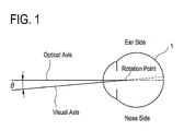
- Fig. 1 is a schematic view showing displacement between an optical axis and a visual axis of an eye.
- an ophthalmic lens is exemplified as an intraocular lens ("IOL") which serves as an alternative to a crystalline lens of an eye.
- the IOL is optically designed in a way of setting a model by inclining an optical system including a cornea and the IOL at a predetermined angle in consideration of displacement between an optical axis and a visual axis of an eye, and designing the IOL by use of this model to reduce the effect of aberration of the eye.
- Fig. 1 is a schematic view showing displacement between an optical axis and a visual axis of an eye 1 viewed from above.
- a central fovea is slightly deviated to an ear side than the optical axis of the eye 1. It is therefore well known that the visual axis is not coaxial with the optical axis of the eye and is inclined at a predetermined angle with respect to the optical axis of the eye. However, it is difficult to exactly determine the visual axis.
- a point on the optical axis located closer to a fundus from a corneal vertex by a predetermined distance is a rotation point of the eye and an axis horizontally inclined by a predetermined angle ⁇ relative to the optical axis is treated as the visual axis.
- a displacement angle ⁇ between the optical axis and the visual axis in this embodiment is set at 5° but it is not limited thereto.
- This displacement angle ⁇ may be set in a range of 1° to 10° and more preferably 3° to 7° based on for example an empirical rule.
- the central fovea is slightly deviated to the ear side relative to the optical axis as mentioned above. More specifically, the central fovea is displaced to the ear side relative to the optical axis and also located slightly above a horizontal plane including the optical axis.
- the visual axis also has a slight displacement angle with respect to the optical axis in a vertical direction.
- the displacement angle can be set to be preferably 3° or less, more preferably in a range of 1° to 2° with respect to the optical axis by centering the rotation point, in addition to the aforementioned horizontal displacement angle.
- an existing optical simulation software e.g., ZEMAX
- the optical design in this embodiment is conducted by modeling the optical system including the cornea and the IOL. Modeling such optical system requires a corneal aspheric polynomial coefficient, a curvature (a radius of curvature) of a cornea, a refractive index of the cornea, a distance from the cornea to the IOL, and power or diopter (refractive power) of the IOL.
- a curvature (a radius of curvature) of each of front and back lens surfaces, a refractive index of the IOL, and central thickness of the IOL are required.
- the corneal curvature may further be divided into a curvature of the corneal front surface and a curvature of the corneal back surface.
- the aforementioned information for optical design is input by use of the optical simulation software, and the optical system including the cornea and the IOL is modeled by being inclined to a nose side by a predetermined angle (5°) about the rotation point and to a chin side by a predetermined angle (1°) about the rotation point.
- the axis relatively decentered by the predetermined angle about the rotation point with respect to the optical axis of the optical system including the cornea and the IOL is assumed to be the visual axis.
- the IOL is optically designed into an aspheric shape to minimize aberration generated in the optical system with reference to the axis assumed to be the visual axis.
- a Zernike polynomial is generally used.
- the Zernike polynomial can be described by the following mathematic expression (2).
- An IOL having a general spherical shape uses the 4 th term. Furthermore, the aberration in the modeled optical system including the cornea and the IOL is usually reduced by bringing (approximating) a value obtained by use of the 11 th term close to zero.
- the coefficient a i is a value of the weighting coefficient based on the inclination by the predetermined angle.
- at least one of the front surface and the back surface of the IOL is designed as an aspheric shape. Each curved shape of the front surface and the back surface of the IOL can be described by the following mathematic expression (1).
- the values of the coefficients A to D used in the mathematic expression (1) are appropriately changed to bring (approximate) the value of the 11 th term representing the spherical aberration in the Zernike polynomial to as close to zero as possible in the optical system modeled by use of the optical simulation software. This is repeated to determine the curved shape of the front and/or back surface of the IOL. It is also possible to determine the coefficients A to D by using a similar method taking into consideration the terms representing other aberrations such as the astigmatic aberration and the coma aberration as well as the term representing the spherical aberration in the Zernike polynomial.
- the above embodiment is explained about the design method of the IOL to be used in place of the crystalline lens.
- the present invention is not limited thereto and may be applied to an ophthalmic lens such as a contact lens to be used for eyes.
- Example 1 for performing the IOL optical design using the aforementioned design method is explained below.
- the IOL of a refractive power of 20.0D is designed to design the IOL front surface into an aspheric shape.
- the optical simulation software used herein was ZEMAX.
- the optical system including the cornea and the IOL obtained by use of the optical simulation software is inclined about the rotation point (7.2 mm from the corneal vertex) by 5° in the horizontal direction (to the nose side) and 1° in the vertical direction (to the chin side), thereby creating a starting model.
- the optical design was made by correcting the conic constant and 4 th and 6 th aspheric polynomial coefficients in the expression (1) with respect to the IOL front surface so that the 11 th term in the above nominal becomes as close to zero as possible.
- Table 2 "Cornea” represents an aberration amount ( ⁇ m) of only a set cornea, "Cornea + IOL” represents an aberration amount at the starting time, and "After Correction” represents an aberration amount indicated in the finally decided IOL optical design.
- the 4 th and 6 th aspheric polynomial coefficients finally decided are -5.518272E-04 and -2.919535E-05 respectively.
- the conic constant (Q) in the IOL front surface at that time was 0.767322 and the central thickness of the lens was 0.756 mm.
- the IOL optical design could be made so as to minimize the aberration of the cornea.
Landscapes
- Health & Medical Sciences (AREA)
- Ophthalmology & Optometry (AREA)
- Physics & Mathematics (AREA)
- General Health & Medical Sciences (AREA)
- General Physics & Mathematics (AREA)
- Optics & Photonics (AREA)
- Engineering & Computer Science (AREA)
- Vascular Medicine (AREA)
- Oral & Maxillofacial Surgery (AREA)
- Transplantation (AREA)
- Mathematical Physics (AREA)
- Biomedical Technology (AREA)
- Heart & Thoracic Surgery (AREA)
- Cardiology (AREA)
- Life Sciences & Earth Sciences (AREA)
- Animal Behavior & Ethology (AREA)
- Public Health (AREA)
- Veterinary Medicine (AREA)
- Prostheses (AREA)
- Eyeglasses (AREA)
Abstract
Description
- The present invention relates to a design method of an ophthalmic lens to be worn on or set in an eye in use, such as an intraocular lens and a contact lens.
- Heretofore, there have been known ophthalmic lenses such as an intraocular lens to be set in an eye in place of a crystalline lens and a contact lens to be placed on a cornea. Those ophthalmic lenses mostly have spherical surfaces. However, there has recently been proposed an ophthalmic lens having an aspheric surface optically designed to reduce the effect of aberration of an eye to obtain shaper images.
- Such aspheric ophthalmic lens is designed to reduce the effect of eye aberration as mentioned above. This lens is produced by optical design with reference to an optical axis of the eye, but without consideration of a visual axis of the eye.
- The present invention has a purpose to provide a design method of aspheric ophthalmic lens capable of reducing the effect of aberration of an eye by taking into account a visual axis of the eye.
- To achieve the above purpose, the present invention provides a method of designing an aspheric ophthalmic lens capable of reducing aberration of an eye, comprising: a step of modeling an optical system including a cornea and an ophthalmic lens by inclining the optical system about a rotation point by a predetermined angle in consideration of a displacement angle between an optical axis and a visual axis of the eye; a step of calculating aberration resulting from the modeled optical system; and a step of designing a shape of at least one of a front surface and a back surface of the ophthalmic lens to reduce the aberration resulting from the modeled optical system.
- Further developments of the present invention are given in the dependent claims.
-
Fig. 1 is a schematic view showing displacement between an optical axis and a visual axis of an eye. - A detailed description of a preferred embodiment of the present invention will now be given referring to the accompanying drawing. In this embodiment, an ophthalmic lens is exemplified as an intraocular lens ("IOL") which serves as an alternative to a crystalline lens of an eye. In this embodiment, the IOL is optically designed in a way of setting a model by inclining an optical system including a cornea and the IOL at a predetermined angle in consideration of displacement between an optical axis and a visual axis of an eye, and designing the IOL by use of this model to reduce the effect of aberration of the eye.
-
Fig. 1 is a schematic view showing displacement between an optical axis and a visual axis of aneye 1 viewed from above. A central fovea is slightly deviated to an ear side than the optical axis of theeye 1. It is therefore well known that the visual axis is not coaxial with the optical axis of the eye and is inclined at a predetermined angle with respect to the optical axis of the eye. However, it is difficult to exactly determine the visual axis. In this embodiment, accordingly, it is assumed that a point on the optical axis located closer to a fundus from a corneal vertex by a predetermined distance (e.g., 7.2 mm) is a rotation point of the eye and an axis horizontally inclined by a predetermined angle θ relative to the optical axis is treated as the visual axis. A displacement angle θ between the optical axis and the visual axis in this embodiment is set at 5° but it is not limited thereto. This displacement angle θ may be set in a range of 1° to 10° and more preferably 3° to 7° based on for example an empirical rule. - The central fovea is slightly deviated to the ear side relative to the optical axis as mentioned above. More specifically, the central fovea is displaced to the ear side relative to the optical axis and also located slightly above a horizontal plane including the optical axis. Thus, the visual axis also has a slight displacement angle with respect to the optical axis in a vertical direction. When the IOL is to be optically designed by taking into account the displacement angle in the vertical direction, the displacement angle can be set to be preferably 3° or less, more preferably in a range of 1° to 2° with respect to the optical axis by centering the rotation point, in addition to the aforementioned horizontal displacement angle.
- For performing optical design of the IOL, an existing optical simulation software (e.g., ZEMAX) is used. The optical design in this embodiment is conducted by modeling the optical system including the cornea and the IOL. Modeling such optical system requires a corneal aspheric polynomial coefficient, a curvature (a radius of curvature) of a cornea, a refractive index of the cornea, a distance from the cornea to the IOL, and power or diopter (refractive power) of the IOL. As design information to determine the power of the IOL, a curvature (a radius of curvature) of each of front and back lens surfaces, a refractive index of the IOL, and central thickness of the IOL are required. As information on a corneal shape, an average of quantitatively obtained data on human cornea may be used or information adopted in an existing model eye may be used. The corneal curvature may further be divided into a curvature of the corneal front surface and a curvature of the corneal back surface. In this embodiment, the aforementioned information for optical design is input by use of the optical simulation software, and the optical system including the cornea and the IOL is modeled by being inclined to a nose side by a predetermined angle (5°) about the rotation point and to a chin side by a predetermined angle (1°) about the rotation point. In this way, the axis relatively decentered by the predetermined angle about the rotation point with respect to the optical axis of the optical system including the cornea and the IOL is assumed to be the visual axis. Then, the IOL is optically designed into an aspheric shape to minimize aberration generated in the optical system with reference to the axis assumed to be the visual axis.
- To determine aberration (wave aberration) generated in the modeled optical system, a Zernike polynomial is generally used. The Zernike polynomial can be described by the following mathematic expression (2).
-

Where, Zi is an i-th Zernike term, and ai is a weighting factor in this term. Table 1 shows 1st to 15th Zernike terms and aberrations, which are defined by the following expressions respectively. -
Table 1 i wi(ρ, θ) 1 1 Piston 2 2 ρcosθ Inclination x 3 2 ρsinθ Inclination y 4 
Defocus 5 
Primary Astigmatic Aberration 6 
Primary Astigmatic Aberration 7 
Coma Aberration 8 
Coma Aberration 9 
3 Foil 10 
3 Foil 11 
Spherical Aberration 12 
Secondary Astigmatic Aberration 13 
Secondary Astigmatic Aberration 14 
4 Foil 15 
4 Foil - An IOL having a general spherical shape uses the 4th term. Furthermore, the aberration in the modeled optical system including the cornea and the IOL is usually reduced by bringing (approximating) a value obtained by use of the 11th term close to zero. In this embodiment, to determine the aberration generated in the state where the optical system is inclined about the rotation point by the predetermined angle, the coefficient ai is a value of the weighting coefficient based on the inclination by the predetermined angle.
In order to reduce the aberration in the thus modeled optical system, at least one of the front surface and the back surface of the IOL is designed as an aspheric shape. Each curved shape of the front surface and the back surface of the IOL can be described by the following mathematic expression (1). -

Where "z" is a sag amount, "R" is a radius of curvature, "h" is a distance from a lens center, "Q" is a conic constant, and "A" to "D" are aspheric polynomial terms. In the case where the lens surface is treated as a spherical surface, not an aspheric surface, the conic constant and the aspheric polynomial terms are set to zero. - The values of the coefficients A to D used in the mathematic expression (1) are appropriately changed to bring (approximate) the value of the 11th term representing the spherical aberration in the Zernike polynomial to as close to zero as possible in the optical system modeled by use of the optical simulation software. This is repeated to determine the curved shape of the front and/or back surface of the IOL. It is also possible to determine the coefficients A to D by using a similar method taking into consideration the terms representing other aberrations such as the astigmatic aberration and the coma aberration as well as the term representing the spherical aberration in the Zernike polynomial.
- The above embodiment is explained about the design method of the IOL to be used in place of the crystalline lens. The present invention is not limited thereto and may be applied to an ophthalmic lens such as a contact lens to be used for eyes.
- Example 1 for performing the IOL optical design using the aforementioned design method is explained below. Herein, the IOL of a refractive power of 20.0D is designed to design the IOL front surface into an aspheric shape. The optical simulation software used herein was ZEMAX. Various data needed for the design were set as follows:
Corneal radius of curvature: 7.575 mm, Corneal refractive index: 1.3375, Corneal conic constant (Q): -0.14135, Distance from cornea to iris (pupil): 3.6 mm, Distance from iris to IOL front surface: 0.9 mm, Radius of curvature of IOL front surface: 13.36 mm, Radius of curvature of IOL back surface: -28.59 mm, Refractive index of IOL base material: 1.519, and Design wavelength: 587.56 nm. - With such optical system model, the optical design was made by correcting the conic constant and 4th and 6th aspheric polynomial coefficients in the expression (1) with respect to the IOL front surface so that the 11th term in the above nominal becomes as close to zero as possible. This result is shown in Table 2. In Table 2, "Cornea" represents an aberration amount (µm) of only a set cornea, "Cornea + IOL" represents an aberration amount at the starting time, and "After Correction" represents an aberration amount indicated in the finally decided IOL optical design. Furthermore, the 4th and 6th aspheric polynomial coefficients finally decided are -5.518272E-04 and -2.919535E-05 respectively. The conic constant (Q) in the IOL front surface at that time was 0.767322 and the central thickness of the lens was 0.756 mm.
-
Table 2 Cornea Cornea + IOL After Correction 1st -0.595323468 -0.743662252 -0.067382968 2nd 0.412809469 -0.141036249 0.410480174 3rd 0.082296591 -0.028170886 0.081863017 4th -0.002823135 0.001322866 -0.008098441 5th v0.01663683 0.039674746 0.023109376 6th -0.040039552 0.095506008 0.055641174 7th 0.030649127 -0.010223299 0.029700738 8th 0.153740727 -0.051178866 0.148927832 9th -0.000106208 -0.0008264 -0.000115897 10th -0.000158442 -0.001232564 -0.000172908 11th 0.272336146 0.344518689 0.026917963 12th 8.34338E-07 0.002699888 -0.000258909 13th 1.4689E-07 0.001121567 -0.000107671 14th -3.81915E-07 8.30225E-06 -4.45372E-06 15th -3.64288E-07 8.361E-06 -4.47135E-06 - As shown in Table 2, in the modeled state where the optical system including the cornea and ophthalmic lens is inclined about the rotation point by the predetermined angle in consideration of the displacement angle between the optical axis and the visual axis of the eye, the IOL optical design could be made so as to minimize the aberration of the cornea.
- While the presently preferred embodiment of the present invention has been shown and described, it is to be understood that this disclosure is for the purpose of illustration and that various changes and modifications may be made without departing from the scope of the invention as set forth in the appended claims.
Claims (6)

Applications Claiming Priority (1)
| Application Number | Priority Date | Filing Date | Title |
|---|---|---|---|
| JP2008091764A JP2009244637A (en) | 2008-03-31 | 2008-03-31 | Design method of aspheric ophthalmic lens |
Publications (1)
| Publication Number | Publication Date |
|---|---|
| EP2107417A1 true EP2107417A1 (en) | 2009-10-07 |
Family
ID=40718624
Family Applications (1)
| Application Number | Title | Priority Date | Filing Date |
|---|---|---|---|
| EP20090156602 Withdrawn EP2107417A1 (en) | 2008-03-31 | 2009-03-30 | Design method of aspheric ophthalmic lens |
Country Status (2)
| Country | Link |
|---|---|
| EP (1) | EP2107417A1 (en) |
| JP (1) | JP2009244637A (en) |
Cited By (1)
| Publication number | Priority date | Publication date | Assignee | Title |
|---|---|---|---|---|
| CN120770980A (en) * | 2025-09-09 | 2025-10-14 | 长春理工大学 | Biconcave aspheric large-view-field implantable ocular optical element design method |
Families Citing this family (3)
| Publication number | Priority date | Publication date | Assignee | Title |
|---|---|---|---|---|
| US9207466B2 (en) * | 2013-11-26 | 2015-12-08 | Johnson & Johnson Vision Care, Inc. | Determining lens alignment on an eye using optical wavefronts |
| EP4071544B1 (en) | 2014-07-15 | 2023-08-16 | Menicon Co., Ltd. | Contact lens manufacturing method and contact lens |
| JP7710708B2 (en) * | 2021-04-23 | 2025-07-22 | 東海光学株式会社 | Method for designing and evaluating eyeglass lenses |
Citations (3)
| Publication number | Priority date | Publication date | Assignee | Title |
|---|---|---|---|---|
| EP1329206A2 (en) * | 2001-12-21 | 2003-07-23 | Euro Lens Technology S.p.A | Eye lens profile capable of correcting ametropias associated with astigmatism |
| DE102006021521A1 (en) * | 2006-05-05 | 2007-11-08 | Carl Zeiss Meditec Ag | Aspherical artificial eye lens and method for the construction of such |
| EP1857077A1 (en) * | 2006-05-17 | 2007-11-21 | Alcon Manufacturing, Ltd. | Correction of higher order aberratons in intraocular lenses |
-
2008
- 2008-03-31 JP JP2008091764A patent/JP2009244637A/en active Pending
-
2009
- 2009-03-30 EP EP20090156602 patent/EP2107417A1/en not_active Withdrawn
Patent Citations (4)
| Publication number | Priority date | Publication date | Assignee | Title |
|---|---|---|---|---|
| EP1329206A2 (en) * | 2001-12-21 | 2003-07-23 | Euro Lens Technology S.p.A | Eye lens profile capable of correcting ametropias associated with astigmatism |
| DE102006021521A1 (en) * | 2006-05-05 | 2007-11-08 | Carl Zeiss Meditec Ag | Aspherical artificial eye lens and method for the construction of such |
| WO2007128423A1 (en) | 2006-05-05 | 2007-11-15 | Carl Zeiss Meditec Ag | Aspheric intraocular lens and method for designing such iol |
| EP1857077A1 (en) * | 2006-05-17 | 2007-11-21 | Alcon Manufacturing, Ltd. | Correction of higher order aberratons in intraocular lenses |
Non-Patent Citations (1)
| Title |
|---|
| LIOU L H ET AL: "Anatomically accurate, finite model eye for optical modeling", JOURNAL OF THE OPTICAL SOCIETY OF AMERICA A, OPTICAL SOCIETY OF AMERICA, US, vol. 14, no. 8, 1 August 1997 (1997-08-01), pages 1684 - 1695, XP008082210, ISSN: 1084-7529 * |
Cited By (1)
| Publication number | Priority date | Publication date | Assignee | Title |
|---|---|---|---|---|
| CN120770980A (en) * | 2025-09-09 | 2025-10-14 | 长春理工大学 | Biconcave aspheric large-view-field implantable ocular optical element design method |
Also Published As
| Publication number | Publication date |
|---|---|
| JP2009244637A (en) | 2009-10-22 |
Similar Documents
| Publication | Publication Date | Title |
|---|---|---|
| EP1597623B1 (en) | Methods for designing custom lenses for improved vision and corresponding lenses | |
| US7490937B2 (en) | Series of aspherical contact lenses | |
| EP2833848B1 (en) | Lenses, devices, methods and systems for refractive error | |
| EP3271779B1 (en) | A method for determining an ophthalmic lens having unwanted astigmatism | |
| US7497572B2 (en) | Toric contact lenses with controlled optical power profile | |
| EP2062553B1 (en) | Optimal iol shape factors for ophthalmic lenses | |
| EP1262815B1 (en) | Aberration correction spectacle lens | |
| EP3426191B1 (en) | Intraocular lenses that improve peripheral vision | |
| US8256896B2 (en) | Toric optic for ophthalmic use | |
| EP3656350B1 (en) | Ophthalmic apparatus with corrective meridians having extended tolerance band by modifying refractive powers in uniform meridian distribution | |
| CN101317121B (en) | ophthalmic lens | |
| US20070255401A1 (en) | Design of Inlays With Intrinsic Diopter Power | |
| EP2113226A1 (en) | Multifocal ophthalmic lens | |
| US8317323B2 (en) | Contact lens and method of manufacture | |
| JP5747279B2 (en) | Design method for vision correction lens | |
| CN101331421B (en) | Method for determining spectacle lenses | |
| US20190064543A1 (en) | Atoric Surfaces to Minimize Secondary Astigmatism in Contact Lenses for the Correction of Astigmatism | |
| US7101041B2 (en) | Contact lenses for correcting severe spherical aberration | |
| CN101910912B (en) | Progressive reading and middle-distance lens limited by Zernike expansion | |
| JP2009244637A (en) | Design method of aspheric ophthalmic lens | |
| US20250102829A1 (en) | Optimized Posterior Surface for Toric Contact Lenses | |
| EP1329206B1 (en) | Eye lens profile capable of correcting ametropias associated with astigmatism | |
| NZ515070A (en) | Contact lens with non-circular boundary between periphiral scleral portion and central portion | |
| GB2428813A (en) | Vision test chart | |
| HK1206583B (en) | Lenses, devices, methods and systems for refractive error |
Legal Events
| Date | Code | Title | Description |
|---|---|---|---|
| PUAI | Public reference made under article 153(3) epc to a published international application that has entered the european phase |
Free format text: ORIGINAL CODE: 0009012 |
|
| AK | Designated contracting states |
Kind code of ref document: A1 Designated state(s): AT BE BG CH CY CZ DE DK EE ES FI FR GB GR HR HU IE IS IT LI LT LU LV MC MK MT NL NO PL PT RO SE SI SK TR |
|
| AX | Request for extension of the european patent |
Extension state: AL BA RS |
|
| 17P | Request for examination filed |
Effective date: 20100407 |
|
| AKX | Designation fees paid |
Designated state(s): DE FR GB |
|
| 17Q | First examination report despatched |
Effective date: 20100924 |
|
| STAA | Information on the status of an ep patent application or granted ep patent |
Free format text: STATUS: THE APPLICATION IS DEEMED TO BE WITHDRAWN |
|
| 18D | Application deemed to be withdrawn |
Effective date: 20110205 |