EP2107273A2 - Actuator - Google Patents
Actuator Download PDFInfo
- Publication number
- EP2107273A2 EP2107273A2 EP09251042A EP09251042A EP2107273A2 EP 2107273 A2 EP2107273 A2 EP 2107273A2 EP 09251042 A EP09251042 A EP 09251042A EP 09251042 A EP09251042 A EP 09251042A EP 2107273 A2 EP2107273 A2 EP 2107273A2
- Authority
- EP
- European Patent Office
- Prior art keywords
- actuator
- shaft
- drive shaft
- actuator according
- drive
- Prior art date
- Legal status (The legal status is an assumption and is not a legal conclusion. Google has not performed a legal analysis and makes no representation as to the accuracy of the status listed.)
- Granted
Links
Images

Classifications
-
- F—MECHANICAL ENGINEERING; LIGHTING; HEATING; WEAPONS; BLASTING
- F16—ENGINEERING ELEMENTS AND UNITS; GENERAL MEASURES FOR PRODUCING AND MAINTAINING EFFECTIVE FUNCTIONING OF MACHINES OR INSTALLATIONS; THERMAL INSULATION IN GENERAL
- F16H—GEARING
- F16H25/00—Gearings comprising primarily only cams, cam-followers and screw-and-nut mechanisms
- F16H25/18—Gearings comprising primarily only cams, cam-followers and screw-and-nut mechanisms for conveying or interconverting oscillating or reciprocating motions
- F16H25/20—Screw mechanisms
-
- B—PERFORMING OPERATIONS; TRANSPORTING
- B64—AIRCRAFT; AVIATION; COSMONAUTICS
- B64C—AEROPLANES; HELICOPTERS
- B64C25/00—Alighting gear
- B64C25/02—Undercarriages
- B64C25/08—Undercarriages non-fixed, e.g. jettisonable
- B64C25/10—Undercarriages non-fixed, e.g. jettisonable retractable, foldable, or the like
- B64C25/18—Operating mechanisms
- B64C25/24—Operating mechanisms electric
-
- B—PERFORMING OPERATIONS; TRANSPORTING
- B64—AIRCRAFT; AVIATION; COSMONAUTICS
- B64C—AEROPLANES; HELICOPTERS
- B64C25/00—Alighting gear
- B64C25/02—Undercarriages
- B64C25/08—Undercarriages non-fixed, e.g. jettisonable
- B64C25/10—Undercarriages non-fixed, e.g. jettisonable retractable, foldable, or the like
- B64C25/18—Operating mechanisms
- B64C25/26—Control or locking systems therefor
-
- F—MECHANICAL ENGINEERING; LIGHTING; HEATING; WEAPONS; BLASTING
- F16—ENGINEERING ELEMENTS AND UNITS; GENERAL MEASURES FOR PRODUCING AND MAINTAINING EFFECTIVE FUNCTIONING OF MACHINES OR INSTALLATIONS; THERMAL INSULATION IN GENERAL
- F16H—GEARING
- F16H25/00—Gearings comprising primarily only cams, cam-followers and screw-and-nut mechanisms
- F16H25/18—Gearings comprising primarily only cams, cam-followers and screw-and-nut mechanisms for conveying or interconverting oscillating or reciprocating motions
- F16H25/20—Screw mechanisms
- F16H2025/2062—Arrangements for driving the actuator
- F16H2025/2071—Disconnecting drive source from the actuator, e.g. using clutches for release of drive connection during manual control
-
- F—MECHANICAL ENGINEERING; LIGHTING; HEATING; WEAPONS; BLASTING
- F16—ENGINEERING ELEMENTS AND UNITS; GENERAL MEASURES FOR PRODUCING AND MAINTAINING EFFECTIVE FUNCTIONING OF MACHINES OR INSTALLATIONS; THERMAL INSULATION IN GENERAL
- F16H—GEARING
- F16H25/00—Gearings comprising primarily only cams, cam-followers and screw-and-nut mechanisms
- F16H25/18—Gearings comprising primarily only cams, cam-followers and screw-and-nut mechanisms for conveying or interconverting oscillating or reciprocating motions
- F16H25/20—Screw mechanisms
- F16H2025/2062—Arrangements for driving the actuator
- F16H2025/2075—Coaxial drive motors
-
- F—MECHANICAL ENGINEERING; LIGHTING; HEATING; WEAPONS; BLASTING
- F16—ENGINEERING ELEMENTS AND UNITS; GENERAL MEASURES FOR PRODUCING AND MAINTAINING EFFECTIVE FUNCTIONING OF MACHINES OR INSTALLATIONS; THERMAL INSULATION IN GENERAL
- F16H—GEARING
- F16H25/00—Gearings comprising primarily only cams, cam-followers and screw-and-nut mechanisms
- F16H25/18—Gearings comprising primarily only cams, cam-followers and screw-and-nut mechanisms for conveying or interconverting oscillating or reciprocating motions
- F16H25/20—Screw mechanisms
- F16H25/22—Screw mechanisms with balls, rollers, or similar members between the co-operating parts; Elements essential to the use of such members
- F16H25/2204—Screw mechanisms with balls, rollers, or similar members between the co-operating parts; Elements essential to the use of such members with balls
-
- Y—GENERAL TAGGING OF NEW TECHNOLOGICAL DEVELOPMENTS; GENERAL TAGGING OF CROSS-SECTIONAL TECHNOLOGIES SPANNING OVER SEVERAL SECTIONS OF THE IPC; TECHNICAL SUBJECTS COVERED BY FORMER USPC CROSS-REFERENCE ART COLLECTIONS [XRACs] AND DIGESTS
- Y10—TECHNICAL SUBJECTS COVERED BY FORMER USPC
- Y10T—TECHNICAL SUBJECTS COVERED BY FORMER US CLASSIFICATION
- Y10T74/00—Machine element or mechanism
- Y10T74/18—Mechanical movements
- Y10T74/18568—Reciprocating or oscillating to or from alternating rotary
- Y10T74/18576—Reciprocating or oscillating to or from alternating rotary including screw and nut
- Y10T74/18688—Limit stop
-
- Y—GENERAL TAGGING OF NEW TECHNOLOGICAL DEVELOPMENTS; GENERAL TAGGING OF CROSS-SECTIONAL TECHNOLOGIES SPANNING OVER SEVERAL SECTIONS OF THE IPC; TECHNICAL SUBJECTS COVERED BY FORMER USPC CROSS-REFERENCE ART COLLECTIONS [XRACs] AND DIGESTS
- Y10—TECHNICAL SUBJECTS COVERED BY FORMER USPC
- Y10T—TECHNICAL SUBJECTS COVERED BY FORMER US CLASSIFICATION
- Y10T74/00—Machine element or mechanism
- Y10T74/18—Mechanical movements
- Y10T74/18568—Reciprocating or oscillating to or from alternating rotary
- Y10T74/18576—Reciprocating or oscillating to or from alternating rotary including screw and nut
- Y10T74/18704—Means to selectively lock or retard screw or nut
Definitions
- This invention relates to an actuator, and in particular to an actuator suitable for use in association with the landing gear of an aircraft, although the actuator may be used in other applications.
- the landing gear of an aircraft is typically driven between its stowed and deployed positions by a primary actuator.
- the weight of the landing gear is sufficient that, during deployment, the primary actuator serves primarily to control the speed of movement of the landing gear under the force of gravity towards the deployed position, the primary actuator also serving to drive the landing gear back towards the stowed position after use.
- a hinged stay serves to support the landing gear, when at its deployed position, and an over-centre hinged strut is typically provided to hold or lock the landing gear in its deployed position, a spring arrangement being used to drive the strut to its over-centre, locked position.
- the primary actuator is unable, alone, to drive the landing gear from its fully deployed position to its stowed position, and a secondary actuator is typically provided to drive the strut against the spring biasing thereof to its over-centre position, thereby releasing the locking effect of the over-centre strut and permitting the primary actuator, in conjunction with further movement of the secondary actuator, to then drive the landing gear to its stowed position.
- an actuator comprising an actuator shaft mounted for rotation by a drive shaft, releasable lock means operable to restrict axial movement of the actuator shaft relative to the drive shaft, and an output member cooperating with the actuator shaft such that rotation of the actuator shaft drives the output member for translating movement relative to the actuator shaft.
- the actuator shaft may incorporate or be secured to a nut of the ball- or roller-screw type, the output member comprising a threaded shaft, rotation of the nut whilst the shaft is held against rotation causing axial movement of the shaft.
- a motor is preferably arranged to drive the drive shaft, and hence the actuator shaft, for rotation.
- the drive shaft and actuator shaft are preferably splined to one another.
- the drive shaft is preferably mounted for rotation and limited axial movement within a housing, a spring biasing arrangement, preferably in the form of a series of disc springs, biasing the drive shaft towards a predetermined axial position.
- a spring biasing arrangement preferably in the form of a series of disc springs, biasing the drive shaft towards a predetermined axial position. Axial movement of the drive shaft beyond a release position conveniently permits release of the lock means, thereby enabling axial movement of the actuator shaft relative to the drive shaft.
- the lock means preferably comprises a collar mounted upon the actuator shaft, the collar having a plurality of tines or fingers formed thereon.
- the tines preferably bear against a stop to limit radial outward movement thereof, and preferably also bear against a shoulder formed on the drive shaft to secure the actuator shaft against axial movement relative to the drive shaft.
- the loads applied thereto by the landing gear and primary actuator are sufficient to cause axial movement of the drive shaft, actuator shaft and collar beyond the release position, whereon the tines no longer bear against the stop, and the tines can deflect outwards, riding over the shoulder, and permitting separation of the actuator shaft from the drive shaft.
- the shoulder is preferably of ramped form.
- the stop is moveable to a position in which the tines no longer bear against the stop.
- an actuator for example in the form of an electromagnetic actuator, is provided to drive the stop for movement.
- the stop can be driven to a position in which outward deflection of the tines is permitted to allow axial movement of the actuator shaft relative to the drive shaft and housing, even when the load applied to the actuator is relatively low.
- the collar is preferably slidably mounted upon the actuator shaft.
- the actuator shaft is provided with an abutment which is located between the collar and a series of inwardly extending projections, preferably ramped projections, formed on the tines.
- abutment which is located between the collar and a series of inwardly extending projections, preferably ramped projections, formed on the tines.
- Sensors are preferably provided to permit monitoring of the operation of the actuator.
- a sensor is preferably arranged to monitor the rotation or position of the drive shaft. In the event that the drive shaft is sensed to be rotating or in a position other than that corresponding to the rotation or second position of the primary actuator, an associated control system determines that a fault has occurred and the landing gear is moved back to its fully deployed position, and if necessary the lock means will be released in order to permit such movement.
- the landing gear comprises a support leg 10 which is moveable about a mounting 12 secured to the airframe of an aircraft between a stowed position and a deployed position.
- the support leg 10 carries, at its lower end, an axle 14 upon which wheels 16 are mounted.
- a hinged stay 20 is connected between the support leg 10 and the airframe, and a hinged strut arrangement 18 is connected between the stay 20 and the support leg 10.
- a primary actuator 24 is operable to drive the support leg 10 between its stowed position, in which the strut arrangement 18 is folded, and its deployed position.
- the strut arrangement 18 In moving between these positions, the strut arrangement 18 completely unfolds shortly before the fully deployed position is reached, and then flexes, slightly, in the opposite direction, as the fully deployed position is reached. The slight flexing of the strut arrangement 18 results in the strut arrangement 18 being of the over-centre type, the strut arrangement 18 serving, in use, to lock the support leg 10 in its deployed position.
- a powerful spring 25, which may be a coil spring as illustrated or, alternatively, may be a torsion spring, is provided to bias the strut arrangement 18 towards its over-centre, locked position.
- the primary actuator 24 may be thought of as positively driving the support leg 10 both during deployment and stowing of the support leg 10, in practice, the weight of the landing gear is such that for the majority of the deployment operation, the primary actuator 24 serves as a brake, controlling the speed of deployment, rather than positively driving the support leg 10 towards its deployed position.
- the primary actuator 24 alone cannot return the landing gear to its stowed position as to do this the strut arrangement 18 must be moved back beyond its completely unfolded, centre position and the primary actuator 24 which acts upon the support leg 10 is unable to drive the strut arrangement 18 in this manner. Rather, in addition to the primary actuator 24, a secondary actuator 26 is provided to drive the strut arrangement 18 against the action of the spring biasing it to the over-centre position. Once the strut 18 has been moved out of the over-centre position, the primary actuator 24 is able to drive the landing gear to its stowed position.
- the secondary actuator 26 comprises an electrically powered motor 28 including a rotor 29 moveable to drive a drive shaft 30 for rotation.
- the rotor 29 of the motor 28 is supported for rotation relative to a housing 32 by bearings 34.
- a limited amount of axial movement of the drive shaft 30 is permitted relative to the rotor 29, and a series of disc springs 36 are provided therebetween to bias the drive shaft 30 towards a predetermined axial position relative to the rotor 29.
- a splined connection is provided between the rotor 29 of the motor 28 and the drive shaft 30 to transmit drive therebetween and to accommodate such axial movement.
- a hollow actuator shaft 38 is splined to the drive shaft 30 by spline formations 40 such that the actuator shaft 38 is rotatable by the motor 28 and drive shaft 30, whilst being capable of axial sliding movement relative thereto.
- the actuator shaft 38 includes a nut 41 with which an output member 42 in the form of a threaded shaft 44 cooperates via a roller- or ball-screw type coupling such that rotation of the actuator shaft 38 and nut 41 causes the shaft 44 to translate relative to at least part of the actuator shaft 38. It will be appreciated, therefore, that operation of the motor 28 causes translational displacement of the output member 42, the direction of displacement being dependent upon the direction of rotation of the motor 28.
- the output member 42 is connected to the strut arrangement 18 to drive the strut arrangement 18 for movement as described hereinbefore.
- the secondary actuator 26 further includes a releasable lock means 46 operable, in normal use, to substantially prevent axial movement of the actuator shaft 38 relative to the drive shaft 30.
- the lock means 46 comprises a collar 48 carried by the actuator shaft 38, the collar 48 including a flange region 49 and a series of fingers or tines 50, each of which extends in a direction substantially parallel to the axis of the actuator shaft 38, the tines 50 together forming a region of the collar 48 of generally split cylindrical form.
- the tines 50 at their free ends, include radially inwardly extending projections 52 which bear against a radially outwardly extending, ramped shoulder 54 formed on the drive shaft 30.
- the radially outer surfaces of the free ends of the tines 50 bear against an inner surface of a stop in the form of a bearing 56 of cylindrical form.
- the engagement between the tines 50 and the bearing 56 is such that the ends of the tines 50 are unable to deflect outwardly, thus locking the tines 50 in engagement with the shoulder 54 and so serving to resist axial movement of the actuator shaft 38 relative to the drive shaft 30.
- the bearing 56 is mounted to the armature 58 of an electromagnetic actuator 60 which is operable to cause movement of the armature 58 and bearing 56 to a release position in which the tines 50 are disengaged from the bearing 56 and thus outward movement of the ends of the tines 50 is permitted.
- the collar 48 is slidably mounted upon the actuator shaft 38.
- a shoulder 62 is formed on the actuator shaft 38, the shoulder 62 being sandwiched between the flange 49 and a series of radially inwardly extending ramped formations 64 provided on the tines 50 close to the flange 49.
- a position sensor 66 monitors the rotary position of the drive shaft 30.
- the position sensor 66 may take any convenient form such as a shaft encoder or Hall effect sensor.
- the actuator shaft 38 and drive shaft 30 are secured to one another by the lock means 46, and axial movement of the actuator shaft 38 relative to the drive shaft 30 is thus substantially prevented.
- the primary actuator 24 serves to limit the deployment speed
- the secondary actuator 26 serves to control movement of the strut arrangement 18 to its fully unfolded position, and beyond its fully unfolded position to its slightly flexed, over-centre position. In this position, the landing gear is locked in its deployed position and is able to withstand large loadings urging it back towards its stowed position.
- the secondary actuator 26 drives the strut arrangement 18, thereby ensuring that the strut arrangement 18 is driven to and beyond its fully unfolded position, thereby releasing the locking effect of the over-centre nature of the strut arrangement 18, ready for the primary actuator 24, to drive the landing gear to its stowed position.
- the tensile loading applied thereto by the weight of the landing gear and any force applied by the primary actuator 24, together, acting upon the linkage arrangement 18, will urge the actuator shaft 38 to the right, in the orientation illustrated.
- this loading is transmitted to the drive shaft 30 and, by virtue of the sprung mounting of the drive shaft 30 within the housing 32, the drive shaft 30 and actuator shaft 38 are able to undergo limited axial movement.
- the limited axial movement results in the lock means 46 moving, axially, to a position in which the tines 50 no longer engage the bearing 56, outward deflection of the ends of the tines 50 then being permitted.
- the tines 50 are thus able to ride up and over the shoulder 54 of the drive shaft 30, thereby releasing the lock means 46 and allowing unrestricted axial movement of the actuator shaft 38. If necessary, the actuator shaft 38 may become totally disengaged from the drive shaft 30 during this movement. It will be appreciated that, in such circumstances, the jamming of the secondary actuator 26 does not inhibit the movement of the landing gear to its deployed position, although subsequent stowing of the landing gear will not be possible.
- an associated control unit instructs energisation of the electromagnetic actuator 60, causing displacement of the armature 58 associated therewith, and of the bearing 56 mounted upon the armature 58 to the release position.
- the movement of the bearing 56 results in disengagement of the bearing 56 and free ends of the tines 50, thereby allowing the tines 50 to ride over the shoulder 54, releasing the lock means 46 and allowing unrestricted axial movement of the actuator shaft 38 which, as described hereinbefore, ensures that the secondary actuator 26 does not inhibit movement of the landing gear to its deployed, locked position.
- This discrepancy is used to indicate that an actuator failure has occurred in the secondary actuator 26, whereon the stowing operation may be aborted and the landing gear driven, by the primary actuator 24, back to its deployed position. If the jamming of the secondary actuator 26 resists such redeployment of the landing gear, then release of the lock means 46 by either of the techniques described hereinbefore can be used to release the actuator shaft 38 for unrestricted axial movement, thereby ensuring that the failure of the secondary actuator 26 does not inhibit movement of the landing gear to the deployed position.
Landscapes
- Engineering & Computer Science (AREA)
- Mechanical Engineering (AREA)
- Aviation & Aerospace Engineering (AREA)
- General Engineering & Computer Science (AREA)
- Transmission Devices (AREA)
- Mechanical Operated Clutches (AREA)
- Actuator (AREA)
- Valve Device For Special Equipments (AREA)
- Fluid-Driven Valves (AREA)
Abstract
Description
- This invention relates to an actuator, and in particular to an actuator suitable for use in association with the landing gear of an aircraft, although the actuator may be used in other applications.
- The landing gear of an aircraft is typically driven between its stowed and deployed positions by a primary actuator. The weight of the landing gear is sufficient that, during deployment, the primary actuator serves primarily to control the speed of movement of the landing gear under the force of gravity towards the deployed position, the primary actuator also serving to drive the landing gear back towards the stowed position after use. A hinged stay serves to support the landing gear, when at its deployed position, and an over-centre hinged strut is typically provided to hold or lock the landing gear in its deployed position, a spring arrangement being used to drive the strut to its over-centre, locked position.
- Due to the provision of the over-centre strut, the primary actuator is unable, alone, to drive the landing gear from its fully deployed position to its stowed position, and a secondary actuator is typically provided to drive the strut against the spring biasing thereof to its over-centre position, thereby releasing the locking effect of the over-centre strut and permitting the primary actuator, in conjunction with further movement of the secondary actuator, to then drive the landing gear to its stowed position.
- In such an arrangement there is the risk that failure of the secondary actuator, resulting in jamming thereof, may prevent the strut from reaching its fully deployed, over-centre locked position, thus preventing the landing gear from being locked in its fully deployed position. Obviously, if the landing gear cannot be locked in its deployed position, the ability of the aircraft to undertake a safe landing may be impaired. It may also prevent stowing of the landing gear, but this is considered to be less problematic as, provided the landing gear is still able to return to, and be locked in, its fully deployed position, the aircraft is still able to land safely, whereon appropriate repairs to the landing gear can be undertaken.
- It is an object of the invention to provide an actuator suitable for use as the secondary actuator in the arrangement outlined above, in which the risk of failure preventing locking of the landing gear in a fully deployed condition is reduced or minimised.
- According to the present invention there is provided an actuator comprising an actuator shaft mounted for rotation by a drive shaft, releasable lock means operable to restrict axial movement of the actuator shaft relative to the drive shaft, and an output member cooperating with the actuator shaft such that rotation of the actuator shaft drives the output member for translating movement relative to the actuator shaft.
- The actuator shaft may incorporate or be secured to a nut of the ball- or roller-screw type, the output member comprising a threaded shaft, rotation of the nut whilst the shaft is held against rotation causing axial movement of the shaft.
- Where such an actuator is used as the secondary actuator in the application outlined hereinbefore, it will be appreciated that, in the event of a failure in the secondary actuator causing it to become jammed, release of the lock means permits axial movement of the actuator shaft, and thus axial movement of the output member associated therewith, thereby allowing the landing gear to be locked in its fully deployed position.
- A motor is preferably arranged to drive the drive shaft, and hence the actuator shaft, for rotation. The drive shaft and actuator shaft are preferably splined to one another.
- The drive shaft is preferably mounted for rotation and limited axial movement within a housing, a spring biasing arrangement, preferably in the form of a series of disc springs, biasing the drive shaft towards a predetermined axial position. Axial movement of the drive shaft beyond a release position conveniently permits release of the lock means, thereby enabling axial movement of the actuator shaft relative to the drive shaft.
- The lock means preferably comprises a collar mounted upon the actuator shaft, the collar having a plurality of tines or fingers formed thereon. The tines preferably bear against a stop to limit radial outward movement thereof, and preferably also bear against a shoulder formed on the drive shaft to secure the actuator shaft against axial movement relative to the drive shaft.
- In the event of the actuator becoming jammed, the loads applied thereto by the landing gear and primary actuator are sufficient to cause axial movement of the drive shaft, actuator shaft and collar beyond the release position, whereon the tines no longer bear against the stop, and the tines can deflect outwards, riding over the shoulder, and permitting separation of the actuator shaft from the drive shaft.
- The shoulder is preferably of ramped form.
- Preferably, the stop is moveable to a position in which the tines no longer bear against the stop. Conveniently, an actuator, for example in the form of an electromagnetic actuator, is provided to drive the stop for movement. Such an arrangement is advantageous in that the stop can be driven to a position in which outward deflection of the tines is permitted to allow axial movement of the actuator shaft relative to the drive shaft and housing, even when the load applied to the actuator is relatively low.
- The collar is preferably slidably mounted upon the actuator shaft. Conveniently, the actuator shaft is provided with an abutment which is located between the collar and a series of inwardly extending projections, preferably ramped projections, formed on the tines. In use, jamming of the actuator during retraction thereof may result in the abutment causing the tines to bow outwardly, allowing the abutment to pass the projections, and permitting limited axial movement of the actuator shaft relative to the drive shaft and housing.
- Sensors are preferably provided to permit monitoring of the operation of the actuator. For example, a sensor is preferably arranged to monitor the rotation or position of the drive shaft. In the event that the drive shaft is sensed to be rotating or in a position other than that corresponding to the rotation or second position of the primary actuator, an associated control system determines that a fault has occurred and the landing gear is moved back to its fully deployed position, and if necessary the lock means will be released in order to permit such movement.
- The invention will further be described, by way of example, with reference to the accompanying drawings, in which:
-
Figure 1 is a view illustrating an aircraft landing gear and the associated primary and secondary actuators; -
Figure 2 is a sectional view illustrating the secondary actuator of the landing gear ofFigure 1 , in accordance with one embodiment of the invention; and -
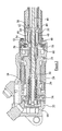
Figure 3 is a sectional view illustrating part of the actuator ofFigure 2 in greater detail. - Referring firstly to
Figure 1 there is illustrated part of the landing gear of an aircraft. The landing gear comprises asupport leg 10 which is moveable about amounting 12 secured to the airframe of an aircraft between a stowed position and a deployed position. Thesupport leg 10 carries, at its lower end, anaxle 14 upon whichwheels 16 are mounted. Ahinged stay 20 is connected between thesupport leg 10 and the airframe, and a hingedstrut arrangement 18 is connected between thestay 20 and thesupport leg 10. Aprimary actuator 24 is operable to drive thesupport leg 10 between its stowed position, in which thestrut arrangement 18 is folded, and its deployed position. In moving between these positions, thestrut arrangement 18 completely unfolds shortly before the fully deployed position is reached, and then flexes, slightly, in the opposite direction, as the fully deployed position is reached. The slight flexing of thestrut arrangement 18 results in thestrut arrangement 18 being of the over-centre type, thestrut arrangement 18 serving, in use, to lock thesupport leg 10 in its deployed position. Apowerful spring 25, which may be a coil spring as illustrated or, alternatively, may be a torsion spring, is provided to bias thestrut arrangement 18 towards its over-centre, locked position. - Although the
primary actuator 24 may be thought of as positively driving thesupport leg 10 both during deployment and stowing of thesupport leg 10, in practice, the weight of the landing gear is such that for the majority of the deployment operation, theprimary actuator 24 serves as a brake, controlling the speed of deployment, rather than positively driving thesupport leg 10 towards its deployed position. - As the
strut arrangement 18 is of the over-centre type, it will be appreciated that theprimary actuator 24 alone cannot return the landing gear to its stowed position as to do this thestrut arrangement 18 must be moved back beyond its completely unfolded, centre position and theprimary actuator 24 which acts upon thesupport leg 10 is unable to drive thestrut arrangement 18 in this manner. Rather, in addition to theprimary actuator 24, asecondary actuator 26 is provided to drive thestrut arrangement 18 against the action of the spring biasing it to the over-centre position. Once thestrut 18 has been moved out of the over-centre position, theprimary actuator 24 is able to drive the landing gear to its stowed position. - As outlined hereinbefore, there is a concern with prior arrangements that failure or jamming of the
secondary actuator 26 whilst the landing gear is being moved towards its deployed position may prevent thestrut arrangement 18 from reaching its over-centre, locked position. Consequently, it may not be possible to lock the landing gear in its deployed position. - As shown in
Figures 2 and3 , thesecondary actuator 26 comprises an electrically poweredmotor 28 including arotor 29 moveable to drive adrive shaft 30 for rotation. Therotor 29 of themotor 28 is supported for rotation relative to ahousing 32 bybearings 34. A limited amount of axial movement of thedrive shaft 30 is permitted relative to therotor 29, and a series ofdisc springs 36 are provided therebetween to bias thedrive shaft 30 towards a predetermined axial position relative to therotor 29. A splined connection is provided between therotor 29 of themotor 28 and thedrive shaft 30 to transmit drive therebetween and to accommodate such axial movement. - A
hollow actuator shaft 38 is splined to thedrive shaft 30 byspline formations 40 such that theactuator shaft 38 is rotatable by themotor 28 and driveshaft 30, whilst being capable of axial sliding movement relative thereto. Theactuator shaft 38 includes anut 41 with which an output member 42 in the form of a threadedshaft 44 cooperates via a roller- or ball-screw type coupling such that rotation of theactuator shaft 38 andnut 41 causes theshaft 44 to translate relative to at least part of theactuator shaft 38. It will be appreciated, therefore, that operation of themotor 28 causes translational displacement of the output member 42, the direction of displacement being dependent upon the direction of rotation of themotor 28. The output member 42 is connected to thestrut arrangement 18 to drive thestrut arrangement 18 for movement as described hereinbefore. - The
secondary actuator 26 further includes a releasable lock means 46 operable, in normal use, to substantially prevent axial movement of theactuator shaft 38 relative to thedrive shaft 30. The lock means 46 comprises acollar 48 carried by theactuator shaft 38, thecollar 48 including aflange region 49 and a series of fingers ortines 50, each of which extends in a direction substantially parallel to the axis of theactuator shaft 38, thetines 50 together forming a region of thecollar 48 of generally split cylindrical form. Thetines 50, at their free ends, include radially inwardly extendingprojections 52 which bear against a radially outwardly extending, rampedshoulder 54 formed on thedrive shaft 30. The radially outer surfaces of the free ends of thetines 50 bear against an inner surface of a stop in the form of abearing 56 of cylindrical form. The engagement between thetines 50 and thebearing 56 is such that the ends of thetines 50 are unable to deflect outwardly, thus locking thetines 50 in engagement with theshoulder 54 and so serving to resist axial movement of theactuator shaft 38 relative to thedrive shaft 30. - The
bearing 56 is mounted to thearmature 58 of anelectromagnetic actuator 60 which is operable to cause movement of thearmature 58 and bearing 56 to a release position in which thetines 50 are disengaged from thebearing 56 and thus outward movement of the ends of thetines 50 is permitted. - The
collar 48 is slidably mounted upon theactuator shaft 38. Ashoulder 62 is formed on theactuator shaft 38, theshoulder 62 being sandwiched between theflange 49 and a series of radially inwardly extending rampedformations 64 provided on thetines 50 close to theflange 49. - A
position sensor 66 monitors the rotary position of thedrive shaft 30. Theposition sensor 66 may take any convenient form such as a shaft encoder or Hall effect sensor. - As set out above, in normal use, the
actuator shaft 38 and driveshaft 30 are secured to one another by the lock means 46, and axial movement of theactuator shaft 38 relative to thedrive shaft 30 is thus substantially prevented. During deployment of the landing gear, theprimary actuator 24 serves to limit the deployment speed, and thesecondary actuator 26 serves to control movement of thestrut arrangement 18 to its fully unfolded position, and beyond its fully unfolded position to its slightly flexed, over-centre position. In this position, the landing gear is locked in its deployed position and is able to withstand large loadings urging it back towards its stowed position. From this position, in order to stow the landing gear, thesecondary actuator 26 drives thestrut arrangement 18, thereby ensuring that thestrut arrangement 18 is driven to and beyond its fully unfolded position, thereby releasing the locking effect of the over-centre nature of thestrut arrangement 18, ready for theprimary actuator 24, to drive the landing gear to its stowed position. - In the event of the
secondary actuator 26 failing and becoming jammed during the deployment operation, the tensile loading applied thereto by the weight of the landing gear and any force applied by theprimary actuator 24, together, acting upon thelinkage arrangement 18, will urge theactuator shaft 38 to the right, in the orientation illustrated. As theactuator shaft 38 and driveshaft 30 are locked to one another against axial movement by the lock means 46, this loading is transmitted to thedrive shaft 30 and, by virtue of the sprung mounting of thedrive shaft 30 within thehousing 32, thedrive shaft 30 andactuator shaft 38 are able to undergo limited axial movement. The limited axial movement results in the lock means 46 moving, axially, to a position in which thetines 50 no longer engage thebearing 56, outward deflection of the ends of thetines 50 then being permitted. Thetines 50 are thus able to ride up and over theshoulder 54 of thedrive shaft 30, thereby releasing the lock means 46 and allowing unrestricted axial movement of theactuator shaft 38. If necessary, theactuator shaft 38 may become totally disengaged from thedrive shaft 30 during this movement. It will be appreciated that, in such circumstances, the jamming of thesecondary actuator 26 does not inhibit the movement of the landing gear to its deployed position, although subsequent stowing of the landing gear will not be possible. - If the
secondary actuator 26 becomes jammed when the landing gear is in a position in which the magnitude of the loading applied by the landing gear to thesecondary actuator 26 is relatively low and insufficient to cause thedrive shaft 30 to move against the action of thesprings 36, for example as may be the case if the failure occurs as the landing gear approaches its fully deployed position, then automatic release of the locking means 46, as described hereinbefore, will not occur. In these circumstances, as soon as the failure of theactuator 26 has been sensed, for example as a result of a discrepancy between the outputs of the driveshaft position sensor 66 and the primary actuator position sensor or alternatively, from the output of a switch associated with thestrut arrangement 18, then an associated control unit instructs energisation of theelectromagnetic actuator 60, causing displacement of thearmature 58 associated therewith, and of thebearing 56 mounted upon thearmature 58 to the release position. The movement of thebearing 56 results in disengagement of thebearing 56 and free ends of thetines 50, thereby allowing thetines 50 to ride over theshoulder 54, releasing the lock means 46 and allowing unrestricted axial movement of theactuator shaft 38 which, as described hereinbefore, ensures that thesecondary actuator 26 does not inhibit movement of the landing gear to its deployed, locked position. - If the
secondary actuator 26 becomes jammed during stowing of the landing gear, this results in theactuator shaft 38 being urged to the left in the orientation illustrated. - Continued operation of the
primary actuator 24 will result in the compressive force experienced by thesecondary actuator 26 being sufficient to force theshoulder 62 of theactuator shaft 38 into engagement with the rampedprojections 64 of thetines 50, urging thetines 50 to bow outwards until a point is reached at which theshoulder 62 moves past theformations 64. It will be apparent that once this point has been reached, a degree of axial movement of theactuator shaft 38 is permitted, and the movement of theactuator shaft 38 through this distance will be sufficient to cause a discrepancy between the sensed drive shaft position and the sensed primary actuator position. This discrepancy is used to indicate that an actuator failure has occurred in thesecondary actuator 26, whereon the stowing operation may be aborted and the landing gear driven, by theprimary actuator 24, back to its deployed position. If the jamming of thesecondary actuator 26 resists such redeployment of the landing gear, then release of the lock means 46 by either of the techniques described hereinbefore can be used to release theactuator shaft 38 for unrestricted axial movement, thereby ensuring that the failure of thesecondary actuator 26 does not inhibit movement of the landing gear to the deployed position. - In this mode of operation it will be appreciated that the limited relative axial movement between the
actuator shaft 38 and thedrive shaft 30 permitted once theshoulder 62 has moved past theformations 64 reduces the risk of further damage being caused to thesecondary actuator 26 prior to the stow operation being aborted. - It will be appreciated that although only a single embodiment of the invention is described hereinbefore, a wide range of modifications and alterations may be made thereto without departing from the scope of the invention.
Claims (14)
- An actuator comprising an actuator shaft (38) mounted for rotation by a drive shaft (30), releasable lock means (46) operable to restrict axial movement of the actuator shaft (38) relative to the drive shaft (30), and an output member (42) cooperating with the actuator shaft (38) such that rotation of the actuator shaft (38) drives the output member (42) for translating movement relative to the actuator shaft (38).
- An actuator according to Claim 1, wherein the actuator shaft (38) incorporates or is secured to a nut (41) of the ball or roller screw type, the output member (42) comprising a threaded shaft (44), rotation of the nut (41) whilst the shaft (44) is held against rotation causing axial movement of the shaft (44).
- An actuator according to Claim 1 or Claim 2, further comprising a motor (28) arranged to drive the drive shaft (30), and hence the actuator shaft (38), for rotation.
- An actuator according to any of the preceding claims, wherein the drive shaft (30) and actuator shaft (38) are splined to one another.
- An actuator according to any of the preceding claims, wherein the drive shaft (30) is mounted for rotation and limited axial movement within a housing, a spring biasing arrangement (36) biasing the drive shaft (30) towards a predetermined axial position, axial movement of the drive shaft (30) beyond a release position permitting release of the lock means (46), thereby enabling axial movement of the actuator shaft (38) relative to the drive shaft (30).
- An actuator according to any of the preceding claims, wherein the lock means (46) comprises a collar (49) mounted upon the actuator shaft (38), the collar (49) having a plurality of tines (50) or fingers formed thereon.
- An actuator according to Claim 6, wherein the tines (50) are engageable with a stop (56) to limit radial outward movement thereof, and also bear against a shoulder (54) formed on the drive shaft (30) to secure the actuator shaft (38) against axial movement relative to the drive shaft (30).
- An actuator according to Claim 7, wherein the shoulder (54) is of ramped form.
- An actuator according to Claim 7 or Claim 8, wherein the stop (56) is movable to a position in which the tines (50) no longer engage the stop (56).
- An actuator according to Claim 9, wherein an electromagnetic actuator (60) is provided to drive the stop (56) for movement.
- An actuator according to any of Claims 6 to 10, wherein the collar (49) is slidably mounted upon the actuator shaft (38).
- An actuator according to Claim 11, wherein the actuator shaft (38) is provided with an abutment (62) which is located between the collar (49) and a series of inwardly extending projections (64) formed on the tines (50).
- An actuator according to Claim 12, wherein the inwardly extending projections (64) are of ramped form.
- An actuator according to any of the preceding claims, further comprising at least one sensor arranged to monitor an operating characteristic of the actuator.
Applications Claiming Priority (1)
| Application Number | Priority Date | Filing Date | Title |
|---|---|---|---|
| GBGB0806025.3A GB0806025D0 (en) | 2008-04-03 | 2008-04-03 | Actuator |
Publications (3)
| Publication Number | Publication Date |
|---|---|
| EP2107273A2 true EP2107273A2 (en) | 2009-10-07 |
| EP2107273A3 EP2107273A3 (en) | 2011-02-16 |
| EP2107273B1 EP2107273B1 (en) | 2012-02-08 |
Family
ID=39433025
Family Applications (1)
| Application Number | Title | Priority Date | Filing Date |
|---|---|---|---|
| EP09251042A Active EP2107273B1 (en) | 2008-04-03 | 2009-04-02 | Actuator |
Country Status (4)
| Country | Link |
|---|---|
| US (1) | US8272285B2 (en) |
| EP (1) | EP2107273B1 (en) |
| AT (1) | ATE544974T1 (en) |
| GB (1) | GB0806025D0 (en) |
Cited By (10)
| Publication number | Priority date | Publication date | Assignee | Title |
|---|---|---|---|---|
| CN102050223A (en) * | 2009-11-04 | 2011-05-11 | 奥格斯塔股份公司 | Aircraft landing gear |
| US20110278394A1 (en) * | 2010-05-11 | 2011-11-17 | Goodrich Corporation | Electrically powered downlock actuation system |
| EP2586703A1 (en) | 2011-10-26 | 2013-05-01 | Eurocopter | landing gear, aircraft and method |
| GB2498208A (en) * | 2012-01-06 | 2013-07-10 | Ge Aviat Systems Ltd | Electrical actuator incorporating a free play mechanism to eliminate force fighting |
| WO2013124636A1 (en) * | 2012-02-24 | 2013-08-29 | Messier-Dowty Limited | Landing gear |
| CN103708026A (en) * | 2013-12-30 | 2014-04-09 | 湖北航达科技有限公司 | Dual-redundancy electric acting barrel |
| FR3019523A1 (en) * | 2014-04-08 | 2015-10-09 | Messier Bugatti Dowty | METHOD FOR OPERATING AIRCRAFT SAIL TRAPPERS, AND ACTUATOR APPLYING THE SAME |
| EP3020632A1 (en) * | 2014-11-13 | 2016-05-18 | Messier-Dowty Ltd | Aircraft landing gear assembly |
| EP3279458A1 (en) * | 2016-08-04 | 2018-02-07 | Goodrich Actuation Systems Limited | Solenoid actuated tine lock |
| EP3166844A4 (en) * | 2014-07-08 | 2018-04-11 | Marine Canada Acquisition Inc. | Electric actuator for a marine steering system |
Families Citing this family (33)
| Publication number | Priority date | Publication date | Assignee | Title |
|---|---|---|---|---|
| CA2710202C (en) * | 2007-12-21 | 2016-03-22 | Messier-Dowty Inc. | Landing gear uplock mechanism employing thermal phase-change actuation |
| FR2946319B1 (en) * | 2009-06-05 | 2012-11-30 | Messier Dowty Sa | METHOD FOR MANEUVERING A BREAKER COUNTERFRAME |
| CN102211660B (en) * | 2011-04-29 | 2013-03-27 | 中航飞机起落架有限责任公司 | Explosion type emergency unlocking device for built-in mechanical lock of actuator cylinder |
| US8794087B2 (en) * | 2012-06-08 | 2014-08-05 | Timotion Technology Co., Ltd. | Gear motor having safety mechanism |
| US9704314B2 (en) * | 2014-08-13 | 2017-07-11 | August Home, Inc. | BLE/WiFi bridge that detects signal strength of Bluetooth LE devices at an exterior of a dwelling |
| US10140828B2 (en) | 2015-06-04 | 2018-11-27 | August Home, Inc. | Intelligent door lock system with camera and motion detector |
| US11072945B2 (en) | 2013-03-15 | 2021-07-27 | August Home, Inc. | Video recording triggered by a smart lock device |
| US9528296B1 (en) | 2013-03-15 | 2016-12-27 | August Home, Inc. | Off center drive mechanism for thumb turning lock system for intelligent door system |
| US11441332B2 (en) | 2013-03-15 | 2022-09-13 | August Home, Inc. | Mesh of cameras communicating with each other to follow a delivery agent within a dwelling |
| US10443266B2 (en) | 2013-03-15 | 2019-10-15 | August Home, Inc. | Intelligent door lock system with manual operation and push notification |
| US10388094B2 (en) | 2013-03-15 | 2019-08-20 | August Home Inc. | Intelligent door lock system with notification to user regarding battery status |
| US11421445B2 (en) | 2013-03-15 | 2022-08-23 | August Home, Inc. | Smart lock device with near field communication |
| US11352812B2 (en) | 2013-03-15 | 2022-06-07 | August Home, Inc. | Door lock system coupled to an image capture device |
| US10181232B2 (en) | 2013-03-15 | 2019-01-15 | August Home, Inc. | Wireless access control system and methods for intelligent door lock system |
| US11527121B2 (en) | 2013-03-15 | 2022-12-13 | August Home, Inc. | Door lock system with contact sensor |
| US11802422B2 (en) | 2013-03-15 | 2023-10-31 | August Home, Inc. | Video recording triggered by a smart lock device |
| US9916746B2 (en) | 2013-03-15 | 2018-03-13 | August Home, Inc. | Security system coupled to a door lock system |
| US11043055B2 (en) | 2013-03-15 | 2021-06-22 | August Home, Inc. | Door lock system with contact sensor |
| US10691953B2 (en) | 2013-03-15 | 2020-06-23 | August Home, Inc. | Door lock system with one or more virtual fences |
| US20150203192A1 (en) * | 2013-05-02 | 2015-07-23 | Goodrich Corporation | System and method for spring assisted landing gear operation |
| GB2523901B (en) | 2013-09-10 | 2016-01-20 | Messier Dowty Ltd | A lock and aircraft landing gear assembly |
| US20150167702A1 (en) * | 2013-12-12 | 2015-06-18 | Triumph Actuation Systems - Yakima, LLC | Actuator assemblies |
| EP3059369B1 (en) * | 2015-02-19 | 2021-09-01 | Goodrich Actuation Systems Ltd. | Actuator mechanism |
| DE202015003619U1 (en) * | 2015-05-19 | 2016-08-22 | Liebherr-Aerospace Lindenberg Gmbh | Locking device of an aircraft landing gear |
| US10124884B2 (en) | 2015-10-09 | 2018-11-13 | Goodrich Aerospace Services Private Limited | Powerless self operated landing gear uplock system |
| WO2018075034A1 (en) | 2016-10-19 | 2018-04-26 | Halliburton Energy Services, Inc. | Controlled stop for a pump |
| CN212203009U (en) * | 2017-09-14 | 2020-12-22 | 日本电产科宝株式会社 | Driving device and electronic apparatus |
| CN108860375B (en) * | 2018-07-18 | 2024-10-01 | 宝岛知仁(山东)新能源有限公司 | Electric vehicle landing gear with failure protection function |
| ES2833527T3 (en) * | 2018-09-26 | 2021-06-15 | Safran Landing Systems Uk Ltd | Aircraft Landing Gear Assembly |
| EP3713058B1 (en) * | 2019-03-20 | 2023-03-01 | Leine & Linde Ab | Adaptive installation rotary encoder |
| US11959308B2 (en) | 2020-09-17 | 2024-04-16 | ASSA ABLOY Residential Group, Inc. | Magnetic sensor for lock position |
| WO2022066470A1 (en) | 2020-09-25 | 2022-03-31 | ASSA ABLOY Residential Group, Inc. | Door lock with magnetometers |
| US12173741B2 (en) * | 2021-05-25 | 2024-12-24 | Brady Fox-Mudge | Self tightening nut and bolt system |
Family Cites Families (7)
| Publication number | Priority date | Publication date | Assignee | Title |
|---|---|---|---|---|
| FR951949A (en) * | 1947-08-09 | 1949-11-07 | Auxiliaire Ind L | Screw jack, with reversible motor, and emergency exit of the rod |
| US3053104A (en) * | 1959-08-06 | 1962-09-11 | Creusot Forges Ateliers | Device for producing regulated rectilinear movements |
| FR1241783A (en) | 1959-08-06 | 1960-09-23 | Creusot Forges Ateliers | Device for performing controlled rectilinear movements |
| FR2895483B1 (en) * | 2005-12-23 | 2008-10-24 | Messier Bugatti Sa | TELESCOPIC ACTUATOR WITH MAIN ROD AND AUXILIARY ROD, AND METHOD USING THE SAME |
| GB0604520D0 (en) * | 2006-03-07 | 2006-04-12 | Smiths Group Plc | Actuators |
| ITTO20060706A1 (en) * | 2006-10-02 | 2008-04-03 | Arol Spa | "HEAD OF SCREWING AND ROLLING FOR THE APPLICATION OF PRE-THREADED CAPS" |
| US7533591B2 (en) * | 2007-03-03 | 2009-05-19 | T-Motion Technology Co., Ltd. | Fast-releasing controlling device of actuator for electric sickbed |
-
2008
- 2008-04-03 GB GBGB0806025.3A patent/GB0806025D0/en not_active Ceased
-
2009
- 2009-04-02 AT AT09251042T patent/ATE544974T1/en active
- 2009-04-02 EP EP09251042A patent/EP2107273B1/en active Active
- 2009-04-02 US US12/417,368 patent/US8272285B2/en not_active Expired - Fee Related
Cited By (26)
| Publication number | Priority date | Publication date | Assignee | Title |
|---|---|---|---|---|
| EP2319760A1 (en) * | 2009-11-04 | 2011-05-11 | Agusta S.p.A. | Aircraft landing gear |
| CN102050223A (en) * | 2009-11-04 | 2011-05-11 | 奥格斯塔股份公司 | Aircraft landing gear |
| US8567717B2 (en) | 2009-11-04 | 2013-10-29 | Agusta S.P.A. | Aircraft landing gear |
| US20110278394A1 (en) * | 2010-05-11 | 2011-11-17 | Goodrich Corporation | Electrically powered downlock actuation system |
| US8590835B2 (en) * | 2010-05-11 | 2013-11-26 | Goodrich Corporation | Electrically powered downlock actuation system |
| EP2386487B1 (en) * | 2010-05-11 | 2021-03-10 | Goodrich Corporation | Electrically powered downlock actuation system |
| US9102402B2 (en) | 2011-10-26 | 2015-08-11 | Airbus Helicopters | Landing gear, an aircraft, and a method |
| EP2586703A1 (en) | 2011-10-26 | 2013-05-01 | Eurocopter | landing gear, aircraft and method |
| FR2981910A1 (en) * | 2011-10-26 | 2013-05-03 | Eurocopter France | LANDFILL, AIRCRAFT AND METHOD |
| GB2498208A (en) * | 2012-01-06 | 2013-07-10 | Ge Aviat Systems Ltd | Electrical actuator incorporating a free play mechanism to eliminate force fighting |
| GB2498208B (en) * | 2012-01-06 | 2017-12-20 | Ge Aviat Systems Ltd | Electrical actuator incorporating a free play mechanism to eliminate force fighting |
| US9004401B2 (en) | 2012-01-06 | 2015-04-14 | Triumph Actuation Systems—UK, Ltd. | Electrical actuator incorporating a free play mechanism to eliminate force fighting |
| WO2013124636A1 (en) * | 2012-02-24 | 2013-08-29 | Messier-Dowty Limited | Landing gear |
| US9555877B2 (en) | 2012-02-24 | 2017-01-31 | Safran Landing Systems Uk Ltd | Landing gear |
| CN104136319A (en) * | 2012-02-24 | 2014-11-05 | 梅西耶道蒂有限公司 | Landing gear |
| CN103708026A (en) * | 2013-12-30 | 2014-04-09 | 湖北航达科技有限公司 | Dual-redundancy electric acting barrel |
| CN103708026B (en) * | 2013-12-30 | 2016-04-20 | 成都飞机工业(集团)有限责任公司 | Two remaining electric actuating cylinder |
| EP2930104A1 (en) * | 2014-04-08 | 2015-10-14 | Messier-Bugatti-Dowty | Method for manoeuvring doors of bays of aircraft, and actuator used therefor. |
| FR3019523A1 (en) * | 2014-04-08 | 2015-10-09 | Messier Bugatti Dowty | METHOD FOR OPERATING AIRCRAFT SAIL TRAPPERS, AND ACTUATOR APPLYING THE SAME |
| CN104973239B (en) * | 2014-04-08 | 2017-07-18 | 梅西耶-布加蒂-道提公司 | Method and its actuator used for operating aircraft cabin door |
| US11396934B2 (en) | 2014-04-08 | 2022-07-26 | Messier-Bugatti-Dowty | Method for maneuvering doors of bays of aircraft, and actuator used therefor |
| EP3166844A4 (en) * | 2014-07-08 | 2018-04-11 | Marine Canada Acquisition Inc. | Electric actuator for a marine steering system |
| EP3020632A1 (en) * | 2014-11-13 | 2016-05-18 | Messier-Dowty Ltd | Aircraft landing gear assembly |
| US10364022B2 (en) | 2014-11-13 | 2019-07-30 | Safran Landing Systems Uk Ltd | Aircraft landing gear assembly |
| US10677194B2 (en) | 2016-08-04 | 2020-06-09 | Goodrich Actuation Systems Limited | Solenoid actuated tine lock |
| EP3279458A1 (en) * | 2016-08-04 | 2018-02-07 | Goodrich Actuation Systems Limited | Solenoid actuated tine lock |
Also Published As
| Publication number | Publication date |
|---|---|
| US8272285B2 (en) | 2012-09-25 |
| ATE544974T1 (en) | 2012-02-15 |
| EP2107273B1 (en) | 2012-02-08 |
| US20090250552A1 (en) | 2009-10-08 |
| EP2107273A3 (en) | 2011-02-16 |
| GB0806025D0 (en) | 2008-05-14 |
Similar Documents
| Publication | Publication Date | Title |
|---|---|---|
| EP2107273B1 (en) | Actuator | |
| EP2318272B1 (en) | Aircraft landing gear actuator | |
| EP2149496B1 (en) | Actuator | |
| EP1902947B1 (en) | Actuator | |
| US7610828B2 (en) | Flight control surface actuator assembly including a free trial mechanism | |
| US8794088B2 (en) | Telescopic actuator | |
| EP2311731B1 (en) | Thrust reverser actuation | |
| US8393442B2 (en) | High gain asymmetry brake | |
| US20120137802A1 (en) | Electromechanical telescopic actuator | |
| US8376862B2 (en) | Motorized spindle drive with overload protection | |
| EP2301845B1 (en) | Thrust reverser actuation | |
| US10900526B2 (en) | Braking device | |
| EP3296586B1 (en) | Actuator no-back arrangement | |
| US12134374B2 (en) | Braking device | |
| US11926407B2 (en) | Jam tolerant rotary actuator | |
| US20250250002A1 (en) | Gear disconnect mechanism for landing gear actuator emergency deployment | |
| WO2005015044A1 (en) | Brakes |
Legal Events
| Date | Code | Title | Description |
|---|---|---|---|
| PUAI | Public reference made under article 153(3) epc to a published international application that has entered the european phase |
Free format text: ORIGINAL CODE: 0009012 |
|
| AK | Designated contracting states |
Kind code of ref document: A2 Designated state(s): AT BE BG CH CY CZ DE DK EE ES FI FR GB GR HR HU IE IS IT LI LT LU LV MC MK MT NL NO PL PT RO SE SI SK TR |
|
| PUAL | Search report despatched |
Free format text: ORIGINAL CODE: 0009013 |
|
| AK | Designated contracting states |
Kind code of ref document: A3 Designated state(s): AT BE BG CH CY CZ DE DK EE ES FI FR GB GR HR HU IE IS IT LI LT LU LV MC MK MT NL NO PL PT RO SE SI SK TR |
|
| AX | Request for extension of the european patent |
Extension state: AL BA RS |
|
| GRAP | Despatch of communication of intention to grant a patent |
Free format text: ORIGINAL CODE: EPIDOSNIGR1 |
|
| 17P | Request for examination filed |
Effective date: 20110811 |
|
| RIC1 | Information provided on ipc code assigned before grant |
Ipc: B64C 25/24 20060101ALI20110909BHEP Ipc: F16H 25/20 20060101AFI20110909BHEP |
|
| GRAS | Grant fee paid |
Free format text: ORIGINAL CODE: EPIDOSNIGR3 |
|
| GRAA | (expected) grant |
Free format text: ORIGINAL CODE: 0009210 |
|
| AK | Designated contracting states |
Kind code of ref document: B1 Designated state(s): AT BE BG CH CY CZ DE DK EE ES FI FR GB GR HR HU IE IS IT LI LT LU LV MC MK MT NL NO PL PT RO SE SI SK TR |
|
| REG | Reference to a national code |
Ref country code: GB Ref legal event code: FG4D |
|
| REG | Reference to a national code |
Ref country code: CH Ref legal event code: EP Ref country code: AT Ref legal event code: REF Ref document number: 544974 Country of ref document: AT Kind code of ref document: T Effective date: 20120215 |
|
| REG | Reference to a national code |
Ref country code: DE Ref legal event code: R096 Ref document number: 602009005207 Country of ref document: DE Effective date: 20120405 |
|
| REG | Reference to a national code |
Ref country code: NL Ref legal event code: VDEP Effective date: 20120208 |
|
| LTIE | Lt: invalidation of european patent or patent extension |
Effective date: 20120208 |
|
| PG25 | Lapsed in a contracting state [announced via postgrant information from national office to epo] |
Ref country code: HR Free format text: LAPSE BECAUSE OF FAILURE TO SUBMIT A TRANSLATION OF THE DESCRIPTION OR TO PAY THE FEE WITHIN THE PRESCRIBED TIME-LIMIT Effective date: 20120208 Ref country code: NL Free format text: LAPSE BECAUSE OF FAILURE TO SUBMIT A TRANSLATION OF THE DESCRIPTION OR TO PAY THE FEE WITHIN THE PRESCRIBED TIME-LIMIT Effective date: 20120208 Ref country code: IS Free format text: LAPSE BECAUSE OF FAILURE TO SUBMIT A TRANSLATION OF THE DESCRIPTION OR TO PAY THE FEE WITHIN THE PRESCRIBED TIME-LIMIT Effective date: 20120608 Ref country code: LT Free format text: LAPSE BECAUSE OF FAILURE TO SUBMIT A TRANSLATION OF THE DESCRIPTION OR TO PAY THE FEE WITHIN THE PRESCRIBED TIME-LIMIT Effective date: 20120208 Ref country code: NO Free format text: LAPSE BECAUSE OF FAILURE TO SUBMIT A TRANSLATION OF THE DESCRIPTION OR TO PAY THE FEE WITHIN THE PRESCRIBED TIME-LIMIT Effective date: 20120508 |
|
| PG25 | Lapsed in a contracting state [announced via postgrant information from national office to epo] |
Ref country code: GR Free format text: LAPSE BECAUSE OF FAILURE TO SUBMIT A TRANSLATION OF THE DESCRIPTION OR TO PAY THE FEE WITHIN THE PRESCRIBED TIME-LIMIT Effective date: 20120509 Ref country code: BE Free format text: LAPSE BECAUSE OF FAILURE TO SUBMIT A TRANSLATION OF THE DESCRIPTION OR TO PAY THE FEE WITHIN THE PRESCRIBED TIME-LIMIT Effective date: 20120208 Ref country code: FI Free format text: LAPSE BECAUSE OF FAILURE TO SUBMIT A TRANSLATION OF THE DESCRIPTION OR TO PAY THE FEE WITHIN THE PRESCRIBED TIME-LIMIT Effective date: 20120208 Ref country code: LV Free format text: LAPSE BECAUSE OF FAILURE TO SUBMIT A TRANSLATION OF THE DESCRIPTION OR TO PAY THE FEE WITHIN THE PRESCRIBED TIME-LIMIT Effective date: 20120208 Ref country code: PL Free format text: LAPSE BECAUSE OF FAILURE TO SUBMIT A TRANSLATION OF THE DESCRIPTION OR TO PAY THE FEE WITHIN THE PRESCRIBED TIME-LIMIT Effective date: 20120208 Ref country code: PT Free format text: LAPSE BECAUSE OF FAILURE TO SUBMIT A TRANSLATION OF THE DESCRIPTION OR TO PAY THE FEE WITHIN THE PRESCRIBED TIME-LIMIT Effective date: 20120608 |
|
| REG | Reference to a national code |
Ref country code: AT Ref legal event code: MK05 Ref document number: 544974 Country of ref document: AT Kind code of ref document: T Effective date: 20120208 |
|
| PG25 | Lapsed in a contracting state [announced via postgrant information from national office to epo] |
Ref country code: CY Free format text: LAPSE BECAUSE OF FAILURE TO SUBMIT A TRANSLATION OF THE DESCRIPTION OR TO PAY THE FEE WITHIN THE PRESCRIBED TIME-LIMIT Effective date: 20120208 |
|
| PG25 | Lapsed in a contracting state [announced via postgrant information from national office to epo] |
Ref country code: EE Free format text: LAPSE BECAUSE OF FAILURE TO SUBMIT A TRANSLATION OF THE DESCRIPTION OR TO PAY THE FEE WITHIN THE PRESCRIBED TIME-LIMIT Effective date: 20120208 Ref country code: SE Free format text: LAPSE BECAUSE OF FAILURE TO SUBMIT A TRANSLATION OF THE DESCRIPTION OR TO PAY THE FEE WITHIN THE PRESCRIBED TIME-LIMIT Effective date: 20120208 Ref country code: RO Free format text: LAPSE BECAUSE OF FAILURE TO SUBMIT A TRANSLATION OF THE DESCRIPTION OR TO PAY THE FEE WITHIN THE PRESCRIBED TIME-LIMIT Effective date: 20120208 Ref country code: DK Free format text: LAPSE BECAUSE OF FAILURE TO SUBMIT A TRANSLATION OF THE DESCRIPTION OR TO PAY THE FEE WITHIN THE PRESCRIBED TIME-LIMIT Effective date: 20120208 Ref country code: CZ Free format text: LAPSE BECAUSE OF FAILURE TO SUBMIT A TRANSLATION OF THE DESCRIPTION OR TO PAY THE FEE WITHIN THE PRESCRIBED TIME-LIMIT Effective date: 20120208 Ref country code: SI Free format text: LAPSE BECAUSE OF FAILURE TO SUBMIT A TRANSLATION OF THE DESCRIPTION OR TO PAY THE FEE WITHIN THE PRESCRIBED TIME-LIMIT Effective date: 20120208 |
|
| PG25 | Lapsed in a contracting state [announced via postgrant information from national office to epo] |
Ref country code: IT Free format text: LAPSE BECAUSE OF FAILURE TO SUBMIT A TRANSLATION OF THE DESCRIPTION OR TO PAY THE FEE WITHIN THE PRESCRIBED TIME-LIMIT Effective date: 20120208 Ref country code: MC Free format text: LAPSE BECAUSE OF NON-PAYMENT OF DUE FEES Effective date: 20120430 Ref country code: SK Free format text: LAPSE BECAUSE OF FAILURE TO SUBMIT A TRANSLATION OF THE DESCRIPTION OR TO PAY THE FEE WITHIN THE PRESCRIBED TIME-LIMIT Effective date: 20120208 |
|
| PLBE | No opposition filed within time limit |
Free format text: ORIGINAL CODE: 0009261 |
|
| STAA | Information on the status of an ep patent application or granted ep patent |
Free format text: STATUS: NO OPPOSITION FILED WITHIN TIME LIMIT |
|
| 26N | No opposition filed |
Effective date: 20121109 |
|
| REG | Reference to a national code |
Ref country code: IE Ref legal event code: MM4A |
|
| PG25 | Lapsed in a contracting state [announced via postgrant information from national office to epo] |
Ref country code: IE Free format text: LAPSE BECAUSE OF NON-PAYMENT OF DUE FEES Effective date: 20120402 Ref country code: AT Free format text: LAPSE BECAUSE OF FAILURE TO SUBMIT A TRANSLATION OF THE DESCRIPTION OR TO PAY THE FEE WITHIN THE PRESCRIBED TIME-LIMIT Effective date: 20120208 |
|
| PG25 | Lapsed in a contracting state [announced via postgrant information from national office to epo] |
Ref country code: MK Free format text: LAPSE BECAUSE OF FAILURE TO SUBMIT A TRANSLATION OF THE DESCRIPTION OR TO PAY THE FEE WITHIN THE PRESCRIBED TIME-LIMIT Effective date: 20120208 |
|
| REG | Reference to a national code |
Ref country code: DE Ref legal event code: R097 Ref document number: 602009005207 Country of ref document: DE Effective date: 20121109 |
|
| PG25 | Lapsed in a contracting state [announced via postgrant information from national office to epo] |
Ref country code: ES Free format text: LAPSE BECAUSE OF FAILURE TO SUBMIT A TRANSLATION OF THE DESCRIPTION OR TO PAY THE FEE WITHIN THE PRESCRIBED TIME-LIMIT Effective date: 20120519 |
|
| PG25 | Lapsed in a contracting state [announced via postgrant information from national office to epo] |
Ref country code: BG Free format text: LAPSE BECAUSE OF FAILURE TO SUBMIT A TRANSLATION OF THE DESCRIPTION OR TO PAY THE FEE WITHIN THE PRESCRIBED TIME-LIMIT Effective date: 20120508 Ref country code: MT Free format text: LAPSE BECAUSE OF FAILURE TO SUBMIT A TRANSLATION OF THE DESCRIPTION OR TO PAY THE FEE WITHIN THE PRESCRIBED TIME-LIMIT Effective date: 20120208 |
|
| REG | Reference to a national code |
Ref country code: CH Ref legal event code: PL |
|
| PG25 | Lapsed in a contracting state [announced via postgrant information from national office to epo] |
Ref country code: LI Free format text: LAPSE BECAUSE OF NON-PAYMENT OF DUE FEES Effective date: 20130430 Ref country code: CH Free format text: LAPSE BECAUSE OF NON-PAYMENT OF DUE FEES Effective date: 20130430 |
|
| PG25 | Lapsed in a contracting state [announced via postgrant information from national office to epo] |
Ref country code: TR Free format text: LAPSE BECAUSE OF FAILURE TO SUBMIT A TRANSLATION OF THE DESCRIPTION OR TO PAY THE FEE WITHIN THE PRESCRIBED TIME-LIMIT Effective date: 20120208 |
|
| PG25 | Lapsed in a contracting state [announced via postgrant information from national office to epo] |
Ref country code: LU Free format text: LAPSE BECAUSE OF NON-PAYMENT OF DUE FEES Effective date: 20120402 |
|
| PG25 | Lapsed in a contracting state [announced via postgrant information from national office to epo] |
Ref country code: HU Free format text: LAPSE BECAUSE OF FAILURE TO SUBMIT A TRANSLATION OF THE DESCRIPTION OR TO PAY THE FEE WITHIN THE PRESCRIBED TIME-LIMIT Effective date: 20090402 |
|
| REG | Reference to a national code |
Ref country code: FR Ref legal event code: PLFP Year of fee payment: 8 |
|
| REG | Reference to a national code |
Ref country code: FR Ref legal event code: PLFP Year of fee payment: 9 |
|
| REG | Reference to a national code |
Ref country code: FR Ref legal event code: PLFP Year of fee payment: 10 |
|
| P01 | Opt-out of the competence of the unified patent court (upc) registered |
Effective date: 20230706 |
|
| PGFP | Annual fee paid to national office [announced via postgrant information from national office to epo] |
Ref country code: FR Payment date: 20250319 Year of fee payment: 17 |
|
| PGFP | Annual fee paid to national office [announced via postgrant information from national office to epo] |
Ref country code: DE Payment date: 20250319 Year of fee payment: 17 |
|
| PGFP | Annual fee paid to national office [announced via postgrant information from national office to epo] |
Ref country code: GB Payment date: 20260327 Year of fee payment: 18 |