EP2107214A1 - Chambered airfoil cooling - Google Patents
Chambered airfoil cooling Download PDFInfo
- Publication number
- EP2107214A1 EP2107214A1 EP09250728A EP09250728A EP2107214A1 EP 2107214 A1 EP2107214 A1 EP 2107214A1 EP 09250728 A EP09250728 A EP 09250728A EP 09250728 A EP09250728 A EP 09250728A EP 2107214 A1 EP2107214 A1 EP 2107214A1
- Authority
- EP
- European Patent Office
- Prior art keywords
- baffle
- dividers
- recited
- airfoil
- internal cavity
- Prior art date
- Legal status (The legal status is an assumption and is not a legal conclusion. Google has not performed a legal analysis and makes no representation as to the accuracy of the status listed.)
- Granted
Links
Images



Classifications
-
- F—MECHANICAL ENGINEERING; LIGHTING; HEATING; WEAPONS; BLASTING
- F01—MACHINES OR ENGINES IN GENERAL; ENGINE PLANTS IN GENERAL; STEAM ENGINES
- F01D—NON-POSITIVE DISPLACEMENT MACHINES OR ENGINES, e.g. STEAM TURBINES
- F01D5/00—Blades; Blade-carrying members; Heating, heat-insulating, cooling or antivibration means on the blades or the members
- F01D5/12—Blades
- F01D5/14—Form or construction
- F01D5/18—Hollow blades, i.e. blades with cooling or heating channels or cavities; Heating, heat-insulating or cooling means on blades
- F01D5/187—Convection cooling
- F01D5/188—Convection cooling with an insert in the blade cavity to guide the cooling fluid, e.g. forming a separation wall
-
- F—MECHANICAL ENGINEERING; LIGHTING; HEATING; WEAPONS; BLASTING
- F05—INDEXING SCHEMES RELATING TO ENGINES OR PUMPS IN VARIOUS SUBCLASSES OF CLASSES F01-F04
- F05D—INDEXING SCHEME FOR ASPECTS RELATING TO NON-POSITIVE-DISPLACEMENT MACHINES OR ENGINES, GAS-TURBINES OR JET-PROPULSION PLANTS
- F05D2260/00—Function
- F05D2260/20—Heat transfer, e.g. cooling
- F05D2260/201—Heat transfer, e.g. cooling by impingement of a fluid
Definitions
- This disclosure generally relates to an airfoil including an internal cooling chamber and baffle. More particularly, this disclosure relates to an airfoil including chambers for preferentially directing cooling air within the cooling chamber.
- An airfoil utilized within a gas turbine engine includes a cooling chamber within which cooling air flows to remove heat from an inner surface of a wall exposed to extreme temperatures.
- a baffle within the cooling chamber includes a plurality of openings for directing air to impinge directly against the inner surface of the hot wall. The impingement of the cooling air against the hot wall improves cooling efficiencies.
- cooling air that has impinged against the hot wall is warmed and flows toward an exhaust opening opposite from the inlet.
- the warmer air mixes with the cooler air causing a non-uniform temperature of the cooling air that results in non-uniform cooling along the airfoil. This can result in higher airfoil temperatures in the airfoil as the distance from the inlet increases.
- the non-uniform and increasing temperatures can reduce cooling efficiency.
- An exemplary airfoil assembly includes an airfoil that has at least one cavity disposed between a baffle and internal walls for preferentially directing cooling air to provide uniform flow cooling along the airfoil.
- the exemplary cavity includes dividers disposed between the baffle and the internal walls of the cavity that direct air to leading and trailing edge chambers to prevent uneven distribution of cooling air from a cooling air inlet to an exhaust outlet. Dividers between the baffle and the cavity walls generate a substantially uniform distribution of cooling air over the airfoil.
- a turbine vane 10 includes an outer flange 12 and an inner flange 14. Extending between the outer flange 12 and the inner flange 14 is an airfoil 16.
- the airfoil 16 includes a plurality of cavities 18 separated by ribs 15 through which cooling air is flown.
- a baffle 20 is inserted into at least one of the cavities 18.
- the baffle 20 includes a plurality of openings 28 that direct cooling air outwardly against an interior surface, or hot wall of the cavities 18.
- the airfoil 16 includes a leading edge 22 and a trailing edge 24.
- the airfoil assembly 16 is exposed to the extreme temperature conditions of hot gas flow emanating from the combustion chamber of the gas turbine engine. Accordingly, the cooling airflow through the cavities 18 provide a cooling function to remove at least some of the heat that is encountered by the airfoil 16.
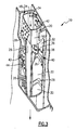
- the turbine vane assembly 10 is shown with one of the cavities 18 cutaway to expose the plurality of openings 28 within the baffle 20.
- Dividers 26 extend from an interior wall 32 of the cavity 18 and come into direct contact with an exterior wall of the baffle 20. These dividers 26 define chambers 30. The chambers 30 prevent cooling air from flowing downwardly between the internal walls of the cavity 18 and the baffle 20. The dividers 26 prevent cooling air from flowing vertically the length of the airfoil 16 but instead direct air transverse to the direction of impingement towards the leading and trailing edges of the airfoil 16.
- the turbine vane assembly 10 illustrates airflow into the baffle 20.
- Airflow indicated at 34 enters the top portion of the baffle 20 and moves downwardly towards an exhaust outlet of the turbine vane assembly 10.
- Cooling air exits through one of the pluralities of openings 28 to impinge on the hot interior wall 32 of the cavity 18. Impingement of the cooling air flow 36 on the hot wall 32 provides a reduction in temperature and results in a warming of the cooling air 36.
- the cooling air is then directed towards the leading edge and trailing edge of the airfoil 16.
- the direction or transverse flow direction relative to the impingement flow is indicated at 38 and prevents warmer air from flowing down the airfoil 16.
- Each of the dividers 26 defines a substantially horizontal chamber 30 between the baffle 20 and the interior wall 32.
- the horizontal chambers 30 direct airflow to vertical chambers 48, 50 at the leading and trailing edges of the cavity 18.
- the vertical chambers 48, 50 allow air to be exhausted out from the cavity 18.
- the example dividers 26 are chevron shaped to further direct airflow in a slight downward direction towards vertical chambers 48, 50.
- the example dividers 26 are chevron shaped to further direct airflow in a slight downward direction towards vertical chambers 48, 50.
- Within the chamber 30 are also trip strips 44.
- the trip strips 44 extend in this example from the interior cavity walls partially into the chamber 30. The trip strips 44 create a turbulent airflow to improve cooling characteristics within each of the chambers 30.
- Airflow enters the inlet opening 25 into the baffle 20. This airflow then exits through one of the plurality of openings 28 to impinge, as indicated at 42 on the hot wall of the cavity 18.
- the impingement airflow 42 provides cooling on the hot wall of the airfoil 16. Airflow then is directed towards the vertical chambers 48, 50.
- the dividers 26 prevent air from moving vertically in the space between the baffle 20 and the hot wall 32. Instead, air is directed towards the vertical chambers 48, 50 such that each chamber 30 receives cooling air that exits through a plurality of openings 28 within the baffle 20.
- the cooling air within the baffle 20 is cooler than that within the space between the baffle 20 and the interior walls once it has impinged and absorbed heat from the hot wall 32.
- a chamber 30 that is closest to the entrance 28 includes cooling air at substantially the same temperature as cooling air in a chamber 30 closer to the exhaust opening.
- the airflow exits the chambers 30 as is indicated at 42 and flows downwardly through the vertical chamber 50.
- the vertical chamber 48 is disposed at an opposite side of the baffle 20 and also exhausts cooling airflow from the cavity 18.
- the baffle 20 includes the plurality of openings 28 from which air is expelled to impinge on the hot wall 32.
- the chambers 30 restrict and direct the flow of air transverse to the flow impingement air and prevent cooling air from flowing vertically downward and warming cooling air further down the airfoil 16. Instead, cooling air is directed transversely towards the vertical chamber 50 or 48.
- the ribs used to divide cavities 18 from each other are heated by the warmer cooling air that has absorbed heat from the hot interior wall 32 as air flows into chambers 50 and 48 from chambers 30 and down the airfoil.
- the air flowing in chambers 50 and 48 helps warm the ribs used to divide cavities 18 from each other thereby reducing the thermal difference between ribs 15 ( Figure 1 ) dividing cavity 18 and the hot wall 32.
- Warmed air from chamber 30 exits chamber 30 into chambers 50 and 48 and warms the rib 15 between cavity 18 to at least partially equalize or reduce any thermal difference between the hot wall 32 and the ribs 15 between cavity 18.
- the reduction in thermal gradients improves durability.
- Figure 7 illustrates impingement of airflow along the hot wall 32 that proceeds transversely from the impingement airflow towards one of the vertical chambers 50, 48.
- This direction of airflow provides for a substantially uniform cooling airflow temperature to impinge along the entire length of the airfoil 16.
- each cavity prevents warmer air from moving vertically. This prevents warmed cooling air from above from causing uneven temperature distributions along the length of the airfoil 16.
- the example dividers 64 that define the various chambers between baffle 62 and the hot walls 32 can be provided in several different configurations.
- the dividers 26 were part of the airfoil 16 and extended from the hot wall 32 inwardly to contact the baffle 62.
- Figure 8 illustrates a vane assembly 60 where the baffle 62 includes a plurality of dividers 64 that extends from the baffle 62 towards the hot walls 32 of the cavity 18.
- the baffle 62 includes the divider 64 that is an integral part of the baffle 62 that extends outwardly.
- another vane assembly 68 includes a baffle 70 with dividers 72 that are secured separately to an exterior surface of the baffle 70.
- the dividers 72 are welded, or attached to the baffle 70 using known methods. Separate attachment of the dividers 72 provides for the formation of the baffle 70 as a relatively simple cylinder.
- another vane assembly 76 includes a baffle 78 and a plurality of compliant dividers 80.
- the plurality of dividers 80 are compliant to accommodate relative expansion and contraction between the baffle 78 and the vane assembly 76.
- the compliant dividers 80 in this example are attached to the baffles 78; however, other compliant features may be incorporated into other features of the cavity.
Landscapes
- Engineering & Computer Science (AREA)
- Mechanical Engineering (AREA)
- General Engineering & Computer Science (AREA)
- Turbine Rotor Nozzle Sealing (AREA)
Abstract
Description
- This disclosure generally relates to an airfoil including an internal cooling chamber and baffle. More particularly, this disclosure relates to an airfoil including chambers for preferentially directing cooling air within the cooling chamber.
- An airfoil utilized within a gas turbine engine includes a cooling chamber within which cooling air flows to remove heat from an inner surface of a wall exposed to extreme temperatures. A baffle within the cooling chamber includes a plurality of openings for directing air to impinge directly against the inner surface of the hot wall. The impingement of the cooling air against the hot wall improves cooling efficiencies.
- Disadvantageously, cooling air that has impinged against the hot wall is warmed and flows toward an exhaust opening opposite from the inlet. The warmer air mixes with the cooler air causing a non-uniform temperature of the cooling air that results in non-uniform cooling along the airfoil. This can result in higher airfoil temperatures in the airfoil as the distance from the inlet increases. The non-uniform and increasing temperatures can reduce cooling efficiency.
- Accordingly, it is desirable to design and develop a cooling air baffle and chamber that increases cooling air efficiency and provides uniform cooling air temperatures along the airfoil.
- An exemplary airfoil assembly includes an airfoil that has at least one cavity disposed between a baffle and internal walls for preferentially directing cooling air to provide uniform flow cooling along the airfoil.
- The exemplary cavity includes dividers disposed between the baffle and the internal walls of the cavity that direct air to leading and trailing edge chambers to prevent uneven distribution of cooling air from a cooling air inlet to an exhaust outlet. Dividers between the baffle and the cavity walls generate a substantially uniform distribution of cooling air over the airfoil.
- These and other features of the present invention can be best understood from the following specification and drawings, the following of which is a brief description.
-
-
Figure 1 is a perspective view of an example turbine vane assembly including a baffle within an internal cavity. -
Figure 2 is a partially sectioned view of the example turbine vane assembly. -
Figure 3 is another partially sectioned view of the example turbine vane assembly including chambers for directing cooling air flow. -
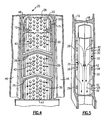
Figure 4 is a side sectional view of the example turbine vane assembly including transverse airflow chambers. -
Figure 5 is a front sectional view of the example turbine vane assembly exposing an example leading edge exhaust chamber. -
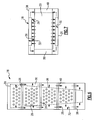
Figure 6 , is a schematic view of airflow through the example turbine vane assembly. -
Figure 7 is a schematic top view of airflow through the example turbine vane assembly. -
Figure 8 is another turbine vane assembly including dividers extending as part of the baffle. -
Figure 9 is another turbine vane assembly including dividers attached to the baffle. -
Figure 10 , is another turbine vane assembly including compliant dividers disposed between the baffle and the cavity walls. - Referring to
Figure 1 , aturbine vane 10 includes anouter flange 12 and aninner flange 14. Extending between theouter flange 12 and theinner flange 14 is anairfoil 16. Theairfoil 16 includes a plurality ofcavities 18 separated byribs 15 through which cooling air is flown. Abaffle 20 is inserted into at least one of thecavities 18. Thebaffle 20 includes a plurality ofopenings 28 that direct cooling air outwardly against an interior surface, or hot wall of thecavities 18. Theairfoil 16 includes a leadingedge 22 and atrailing edge 24. Theairfoil assembly 16 is exposed to the extreme temperature conditions of hot gas flow emanating from the combustion chamber of the gas turbine engine. Accordingly, the cooling airflow through thecavities 18 provide a cooling function to remove at least some of the heat that is encountered by theairfoil 16. - Referring to
Figure 2 , theturbine vane assembly 10 is shown with one of thecavities 18 cutaway to expose the plurality ofopenings 28 within thebaffle 20.Dividers 26 extend from aninterior wall 32 of thecavity 18 and come into direct contact with an exterior wall of thebaffle 20. Thesedividers 26 definechambers 30. Thechambers 30 prevent cooling air from flowing downwardly between the internal walls of thecavity 18 and thebaffle 20. Thedividers 26 prevent cooling air from flowing vertically the length of theairfoil 16 but instead direct air transverse to the direction of impingement towards the leading and trailing edges of theairfoil 16. - Referring to
Figure 3 , theturbine vane assembly 10 illustrates airflow into thebaffle 20. Airflow indicated at 34 enters the top portion of thebaffle 20 and moves downwardly towards an exhaust outlet of theturbine vane assembly 10. During operation, air enters the opening of thebaffle 20 as is indicated by 34 and flows downwardly through thebaffle 20. Cooling air exits through one of the pluralities ofopenings 28 to impinge on the hotinterior wall 32 of thecavity 18. Impingement of thecooling air flow 36 on thehot wall 32 provides a reduction in temperature and results in a warming of thecooling air 36. - The cooling air is then directed towards the leading edge and trailing edge of the
airfoil 16. The direction or transverse flow direction relative to the impingement flow is indicated at 38 and prevents warmer air from flowing down theairfoil 16. - Each of the
dividers 26 defines a substantiallyhorizontal chamber 30 between thebaffle 20 and theinterior wall 32. Thehorizontal chambers 30 direct airflow tovertical chambers cavity 18. Thevertical chambers cavity 18. - The
example dividers 26 are chevron shaped to further direct airflow in a slight downward direction towardsvertical chambers chamber 30 are alsotrip strips 44. Thetrip strips 44 extend in this example from the interior cavity walls partially into thechamber 30. Thetrip strips 44 create a turbulent airflow to improve cooling characteristics within each of thechambers 30. - Referring to
Figures 4 and 5 , the flow of cooling air through thebaffle 20 against the hot walls and through thechambers 30 is shown. Airflow enters the inlet opening 25 into thebaffle 20. This airflow then exits through one of the plurality ofopenings 28 to impinge, as indicated at 42 on the hot wall of thecavity 18. Theimpingement airflow 42 provides cooling on the hot wall of theairfoil 16. Airflow then is directed towards thevertical chambers - The
dividers 26 prevent air from moving vertically in the space between thebaffle 20 and thehot wall 32. Instead, air is directed towards thevertical chambers chamber 30 receives cooling air that exits through a plurality ofopenings 28 within thebaffle 20. As appreciated, the cooling air within thebaffle 20 is cooler than that within the space between thebaffle 20 and the interior walls once it has impinged and absorbed heat from thehot wall 32. Accordingly, achamber 30 that is closest to theentrance 28 includes cooling air at substantially the same temperature as cooling air in achamber 30 closer to the exhaust opening. - Referring to
Figure 5 , the airflow exits thechambers 30 as is indicated at 42 and flows downwardly through thevertical chamber 50. Thevertical chamber 48 is disposed at an opposite side of thebaffle 20 and also exhausts cooling airflow from thecavity 18. - Referring to
Figures 6 and 7 , airflow through thecavity 18 and through thebaffle 20 is illustrated schematically. Thebaffle 20 includes the plurality ofopenings 28 from which air is expelled to impinge on thehot wall 32. Thechambers 30 restrict and direct the flow of air transverse to the flow impingement air and prevent cooling air from flowing vertically downward and warming cooling air further down theairfoil 16. Instead, cooling air is directed transversely towards thevertical chamber - The ribs used to divide
cavities 18 from each other are heated by the warmer cooling air that has absorbed heat from the hotinterior wall 32 as air flows intochambers chambers 30 and down the airfoil. Thus the air flowing inchambers cavities 18 from each other thereby reducing the thermal difference between ribs 15 (Figure 1 ) dividingcavity 18 and thehot wall 32. Warmed air fromchamber 30exits chamber 30 intochambers rib 15 betweencavity 18 to at least partially equalize or reduce any thermal difference between thehot wall 32 and theribs 15 betweencavity 18. The reduction in thermal gradients improves durability. -
Figure 7 illustrates impingement of airflow along thehot wall 32 that proceeds transversely from the impingement airflow towards one of thevertical chambers airfoil 16. As appreciated, each cavity prevents warmer air from moving vertically. This prevents warmed cooling air from above from causing uneven temperature distributions along the length of theairfoil 16. - Referring to
Figure 8 , theexample dividers 64 that define the various chambers betweenbaffle 62 and thehot walls 32 can be provided in several different configurations. In the previous example illustrated inFigures 6 and 7 , thedividers 26 were part of theairfoil 16 and extended from thehot wall 32 inwardly to contact thebaffle 62.Figure 8 illustrates a vane assembly 60 where thebaffle 62 includes a plurality ofdividers 64 that extends from thebaffle 62 towards thehot walls 32 of thecavity 18. Thebaffle 62 includes thedivider 64 that is an integral part of thebaffle 62 that extends outwardly. - Referring to
Figure 9 , anothervane assembly 68 includes abaffle 70 withdividers 72 that are secured separately to an exterior surface of thebaffle 70. Thedividers 72 are welded, or attached to thebaffle 70 using known methods. Separate attachment of thedividers 72 provides for the formation of thebaffle 70 as a relatively simple cylinder. - Referring to
Figure 10 , another vane assembly 76 includes abaffle 78 and a plurality ofcompliant dividers 80. The plurality ofdividers 80 are compliant to accommodate relative expansion and contraction between thebaffle 78 and the vane assembly 76. Thecompliant dividers 80 in this example are attached to thebaffles 78; however, other compliant features may be incorporated into other features of the cavity. - Although a preferred embodiment of this invention has been disclosed, a worker of ordinary skill in this art would recognize that certain modifications would come within the scope of this invention. For that reason, the following claims should be studied to determine the true scope and content of this invention.
Claims (15)
- An airfoil assembly (16) comprising:an airfoil (16) defining at least one internal cavity (18) in communication with a source of cooling air;a baffle (20; 62; 70; 78) disposed within the internal cavity (18) including a plurality of openings (28) for directing cooling air; anda plurality of dividers (26; 64; 72; 80) extending between the baffle and walls (32) of the internal cavity (18) to define a plurality of open ended chambers (30).
- The assembly as recited in claim 1, wherein the plurality of open ended chambers (30) direct airflow transverse to impingement airflow expelled from the plurality of openings (28) within the baffle (20).
- The assembly as recited in claim 1 or 2, wherein each of the open ended chambers (30) is in communication with at least one of a leading edge chamber (48) and a trailing edge chamber (50).
- The assembly as recited in claim 3, wherein the leading edge chamber (48) and the trailing edge chamber (50) extend the entire length of the internal cavity (18).
- The assembly as recited in any preceding claim, including mixing members (44) extending from one of the baffle (20) and the wall (32) of the internal cavity (30) partially into at least one of the plurality of chambers (30) to generate turbulent cooling airflow.
- The assembly as recited in any preceding claim, wherein each of the plurality of dividers (26; 64; 72; 80) includes a chevron shape including ends that are angled toward an exhaust opening.
- The assembly as recited in any preceding claim, wherein the plurality of dividers (80) are compliant to exert a biasing force against both the baffle (78) and the walls (32) of the internal cavity (18).
- The assembly as recited in any preceding claim, wherein the plurality of dividers (26) are part of the walls (32) of the internal cavity (18) and extend inwardly into direct contact with the baffle (20).
- The assembly as recited in any of claims 1 to 7, wherein the plurality of dividers (64; 72; 80) are part of the baffle (62; 70; 78) and extend outwardly from the baffle into direct contact with the walls (32) of the internal cavity (30).
- A method of cooling a turbine airfoil assembly comprising the steps of:a) communicating a cool air flow into an inlet opening (25) of a baffle (20) disposed within an internal cavity (18) of an airfoil assembly;b) directing air out of a plurality of openings (28) of the baffle (20) to impinge upon a hot wall (32) of the airfoil assembly;c) directing cooling air that after impingement on the hot wall (32) of the airfoil transversely with a plurality of dividers (26) defining a corresponding plurality of chambers (30) between the baffle and the hot walls of the airfoil; andd) warming the dividers (26) with the transverse flow of air to reduce a difference in temperature between the plurality of dividers (26) and the hot wall (32).
- The method as recited in claim 10, including the step of directing cooling air transversely toward an exhaust chamber extending the length of the airfoil (16), and, wherein, for example, the exhaust chamber is disposed at the leading edge portion of the internal cavity (18) and another chamber is disposed at the trailing edge portion of the internal cavity (18).
- The method as recited in claim 10 or 11, including the step of generating turbulent flow within at least one of the plurality of chambers (30) with a trip strip (44) that extends partially into the space between the baffle (20) and the hot walls (32) of the internal cavity (18).
- The method as recited in claim 10, 11 or 12, including the step of forming the plurality of dividers (26) in the walls (32) of the internal cavity (18).
- The method as recited in claim 11, 12 or 13, including the step of forming the plurality of dividers (64; 72; 80) in the baffle (62; 70; 78).
- The method as recited in any of claims 10 to 14, wherein the plurality of dividers (80) are compliant to accommodate relative thermal expansion between the baffle (78) and the airfoil (16).
Applications Claiming Priority (1)
| Application Number | Priority Date | Filing Date | Title |
|---|---|---|---|
| US12/058,940 US8393867B2 (en) | 2008-03-31 | 2008-03-31 | Chambered airfoil cooling |
Publications (2)
| Publication Number | Publication Date |
|---|---|
| EP2107214A1 true EP2107214A1 (en) | 2009-10-07 |
| EP2107214B1 EP2107214B1 (en) | 2011-11-02 |
Family
ID=40846899
Family Applications (1)
| Application Number | Title | Priority Date | Filing Date |
|---|---|---|---|
| EP09250728A Active EP2107214B1 (en) | 2008-03-31 | 2009-03-16 | Chambered airfoil cooling |
Country Status (2)
| Country | Link |
|---|---|
| US (1) | US8393867B2 (en) |
| EP (1) | EP2107214B1 (en) |
Cited By (8)
| Publication number | Priority date | Publication date | Assignee | Title |
|---|---|---|---|---|
| WO2015157780A1 (en) * | 2014-04-09 | 2015-10-15 | Siemens Aktiengesellschaft | Internal cooling system with insert forming nearwall cooling channels in an aft cooling cavity of a gas turbine airfoil including heat dissipating ribs |
| EP2898203A4 (en) * | 2012-09-18 | 2015-11-25 | United Technologies Corp | Gas turbine engine component cooling circuit |
| WO2016036366A1 (en) * | 2014-09-04 | 2016-03-10 | Siemens Aktiengesellschaft | Internal cooling system with insert forming nearwall cooling channels in an aft cooling cavity of a gas turbine airfoil |
| WO2016036367A1 (en) * | 2014-09-04 | 2016-03-10 | Siemens Aktiengesellschaft | Internal cooling system with insert forming nearwall cooling channels in midchord cooling cavities of a gas turbine airfoil |
| EP3130756A1 (en) * | 2015-08-12 | 2017-02-15 | United Technologies Corporation | Low turn loss baffle flow diverter |
| EP3150800A1 (en) * | 2015-08-12 | 2017-04-05 | United Technologies Corporation | Airfoil baffle with wedge region |
| DE102015226653A1 (en) | 2015-12-23 | 2017-06-29 | Siemens Aktiengesellschaft | Turbine blade for a thermal turbomachine |
| EP3502417A1 (en) * | 2017-12-22 | 2019-06-26 | United Technologies Corporation | Platform flow turning elements for gas turbine engine components |
Families Citing this family (32)
| Publication number | Priority date | Publication date | Assignee | Title |
|---|---|---|---|---|
| US9403208B2 (en) | 2010-12-30 | 2016-08-02 | United Technologies Corporation | Method and casting core for forming a landing for welding a baffle inserted in an airfoil |
| JP5931351B2 (en) * | 2011-05-13 | 2016-06-08 | 三菱重工業株式会社 | Turbine vane |
| WO2015023338A2 (en) | 2013-05-24 | 2015-02-19 | United Technologies Corporation | Gas turbine engine component having trip strips |
| EP2907974B1 (en) | 2014-02-12 | 2020-10-07 | United Technologies Corporation | Component and corresponding gas turbine engine |
| EP3105437B1 (en) | 2014-02-13 | 2025-02-26 | RTX Corporation | Cooling of hollow turbine engine vanes |
| US9988913B2 (en) | 2014-07-15 | 2018-06-05 | United Technologies Corporation | Using inserts to balance heat transfer and stress in high temperature alloys |
| US10072516B2 (en) * | 2014-09-24 | 2018-09-11 | United Technologies Corporation | Clamped vane arc segment having load-transmitting features |
| US9810084B1 (en) | 2015-02-06 | 2017-11-07 | United Technologies Corporation | Gas turbine engine turbine vane baffle and serpentine cooling passage |
| US9771814B2 (en) * | 2015-03-09 | 2017-09-26 | United Technologies Corporation | Tolerance resistance coverplates |
| US10156147B2 (en) | 2015-12-18 | 2018-12-18 | United Technologies Corporation | Method and apparatus for cooling gas turbine engine component |
| US10450880B2 (en) * | 2016-08-04 | 2019-10-22 | United Technologies Corporation | Air metering baffle assembly |
| US10577954B2 (en) * | 2017-03-27 | 2020-03-03 | Honeywell International Inc. | Blockage-resistant vane impingement tubes and turbine nozzles containing the same |
| US10584596B2 (en) * | 2017-12-22 | 2020-03-10 | United Technologies Corporation | Gas turbine engine components having internal cooling features |
| KR102048863B1 (en) * | 2018-04-17 | 2019-11-26 | 두산중공업 주식회사 | Turbine vane having insert supports |
| US10677071B2 (en) * | 2018-04-19 | 2020-06-09 | Raytheon Technologies Corporation | Turbine vane for gas turbine engine |
| US10787912B2 (en) | 2018-04-25 | 2020-09-29 | Raytheon Technologies Corporation | Spiral cavities for gas turbine engine components |
| US10697309B2 (en) | 2018-04-25 | 2020-06-30 | Raytheon Technologies Corporation | Platform cover plates for gas turbine engine components |
| US11702941B2 (en) * | 2018-11-09 | 2023-07-18 | Raytheon Technologies Corporation | Airfoil with baffle having flange ring affixed to platform |
| US10774657B2 (en) | 2018-11-23 | 2020-09-15 | Raytheon Technologies Corporation | Baffle assembly for gas turbine engine components |
| US10711620B1 (en) * | 2019-01-14 | 2020-07-14 | General Electric Company | Insert system for an airfoil and method of installing same |
| US11994292B2 (en) | 2020-08-31 | 2024-05-28 | General Electric Company | Impingement cooling apparatus for turbomachine |
| US11460191B2 (en) | 2020-08-31 | 2022-10-04 | General Electric Company | Cooling insert for a turbomachine |
| US11994293B2 (en) | 2020-08-31 | 2024-05-28 | General Electric Company | Impingement cooling apparatus support structure and method of manufacture |
| US11371702B2 (en) | 2020-08-31 | 2022-06-28 | General Electric Company | Impingement panel for a turbomachine |
| US11614233B2 (en) | 2020-08-31 | 2023-03-28 | General Electric Company | Impingement panel support structure and method of manufacture |
| US11255545B1 (en) | 2020-10-26 | 2022-02-22 | General Electric Company | Integrated combustion nozzle having a unified head end |
| US11359497B1 (en) * | 2020-12-21 | 2022-06-14 | Raytheon Technologies Corporation | Vane with baffle and recessed spar |
| US11767766B1 (en) | 2022-07-29 | 2023-09-26 | General Electric Company | Turbomachine airfoil having impingement cooling passages |
| GB202216827D0 (en) * | 2022-11-11 | 2022-12-28 | Rolls Royce Plc | A method of manufacturing a turbine component |
| US12281597B2 (en) * | 2023-08-21 | 2025-04-22 | Rtx Corporation | CMC vane with rotatable baffle design to accommodate re-stagger |
| US12326099B2 (en) | 2023-08-21 | 2025-06-10 | Rtx Corporation | Bathtub seal integrated into CMC vane load path |
| US12025029B1 (en) | 2023-08-21 | 2024-07-02 | Rtx Corporation | Bathtub seal for damping CMC vane platform |
Citations (5)
| Publication number | Priority date | Publication date | Assignee | Title |
|---|---|---|---|---|
| FR2149105A5 (en) | 1971-07-30 | 1973-03-23 | Westinghouse Electric Corp | |
| US5253976A (en) * | 1991-11-19 | 1993-10-19 | General Electric Company | Integrated steam and air cooling for combined cycle gas turbines |
| US5772398A (en) * | 1996-01-04 | 1998-06-30 | Societe Nationale D'etude Et De Construction De Moteurs D'aviation "Snecma" | Cooled turbine guide vane |
| EP1136651A1 (en) * | 2000-03-22 | 2001-09-26 | Siemens Aktiengesellschaft | Cooling system for an airfoil |
| US6382908B1 (en) * | 2001-01-18 | 2002-05-07 | General Electric Company | Nozzle fillet backside cooling |
Family Cites Families (15)
| Publication number | Priority date | Publication date | Assignee | Title |
|---|---|---|---|---|
| US3574481A (en) * | 1968-05-09 | 1971-04-13 | James A Pyne Jr | Variable area cooled airfoil construction for gas turbines |
| US3966357A (en) * | 1974-09-25 | 1976-06-29 | General Electric Company | Blade baffle damper |
| US4040767A (en) * | 1975-06-02 | 1977-08-09 | United Technologies Corporation | Coolable nozzle guide vane |
| US4025226A (en) * | 1975-10-03 | 1977-05-24 | United Technologies Corporation | Air cooled turbine vane |
| US4542867A (en) * | 1983-01-31 | 1985-09-24 | United Technologies Corporation | Internally cooled hollow airfoil |
| US5667359A (en) * | 1988-08-24 | 1997-09-16 | United Technologies Corp. | Clearance control for the turbine of a gas turbine engine |
| US5145315A (en) * | 1991-09-27 | 1992-09-08 | Westinghouse Electric Corp. | Gas turbine vane cooling air insert |
| US5207556A (en) * | 1992-04-27 | 1993-05-04 | General Electric Company | Airfoil having multi-passage baffle |
| JPH06129204A (en) * | 1992-10-19 | 1994-05-10 | Mitsubishi Heavy Ind Ltd | Gas turbine cooling structure for gas turbine stator vane |
| US5711650A (en) * | 1996-10-04 | 1998-01-27 | Pratt & Whitney Canada, Inc. | Gas turbine airfoil cooling |
| US6193465B1 (en) * | 1998-09-28 | 2001-02-27 | General Electric Company | Trapped insert turbine airfoil |
| US6142734A (en) * | 1999-04-06 | 2000-11-07 | General Electric Company | Internally grooved turbine wall |
| US6607355B2 (en) * | 2001-10-09 | 2003-08-19 | United Technologies Corporation | Turbine airfoil with enhanced heat transfer |
| US7104756B2 (en) * | 2004-08-11 | 2006-09-12 | United Technologies Corporation | Temperature tolerant vane assembly |
| US8043057B1 (en) * | 2007-12-21 | 2011-10-25 | Florida Turbine Technologies, Inc. | Air cooled turbine airfoil |
-
2008
- 2008-03-31 US US12/058,940 patent/US8393867B2/en active Active
-
2009
- 2009-03-16 EP EP09250728A patent/EP2107214B1/en active Active
Patent Citations (5)
| Publication number | Priority date | Publication date | Assignee | Title |
|---|---|---|---|---|
| FR2149105A5 (en) | 1971-07-30 | 1973-03-23 | Westinghouse Electric Corp | |
| US5253976A (en) * | 1991-11-19 | 1993-10-19 | General Electric Company | Integrated steam and air cooling for combined cycle gas turbines |
| US5772398A (en) * | 1996-01-04 | 1998-06-30 | Societe Nationale D'etude Et De Construction De Moteurs D'aviation "Snecma" | Cooled turbine guide vane |
| EP1136651A1 (en) * | 2000-03-22 | 2001-09-26 | Siemens Aktiengesellschaft | Cooling system for an airfoil |
| US6382908B1 (en) * | 2001-01-18 | 2002-05-07 | General Electric Company | Nozzle fillet backside cooling |
Cited By (17)
| Publication number | Priority date | Publication date | Assignee | Title |
|---|---|---|---|---|
| EP2898203A4 (en) * | 2012-09-18 | 2015-11-25 | United Technologies Corp | Gas turbine engine component cooling circuit |
| WO2015157780A1 (en) * | 2014-04-09 | 2015-10-15 | Siemens Aktiengesellschaft | Internal cooling system with insert forming nearwall cooling channels in an aft cooling cavity of a gas turbine airfoil including heat dissipating ribs |
| CN107075955A (en) * | 2014-09-04 | 2017-08-18 | 西门子公司 | Include the inner cooling system of cooling fin with the insert that nearly wall cooling duct is formed in the rear portion cooling chamber of combustion gas turbine airfoil |
| WO2016036366A1 (en) * | 2014-09-04 | 2016-03-10 | Siemens Aktiengesellschaft | Internal cooling system with insert forming nearwall cooling channels in an aft cooling cavity of a gas turbine airfoil |
| WO2016036367A1 (en) * | 2014-09-04 | 2016-03-10 | Siemens Aktiengesellschaft | Internal cooling system with insert forming nearwall cooling channels in midchord cooling cavities of a gas turbine airfoil |
| CN106795771B (en) * | 2014-09-04 | 2018-11-30 | 西门子公司 | Internal Cooling System with Inserts Forming Near-Wall Cooling Passages in Mid-chord Cooling Cavities of Gas Turbine Airfoils |
| CN106795771A (en) * | 2014-09-04 | 2017-05-31 | 西门子公司 | Inner cooling system with the insert that nearly wall cooling duct is formed in cooling chamber in the middle part of the wing chord of gas turbine aerofoil profile |
| US9863256B2 (en) | 2014-09-04 | 2018-01-09 | Siemens Aktiengesellschaft | Internal cooling system with insert forming nearwall cooling channels in an aft cooling cavity of an airfoil usable in a gas turbine engine |
| US9840930B2 (en) | 2014-09-04 | 2017-12-12 | Siemens Aktiengesellschaft | Internal cooling system with insert forming nearwall cooling channels in midchord cooling cavities of a gas turbine airfoil |
| EP3130756A1 (en) * | 2015-08-12 | 2017-02-15 | United Technologies Corporation | Low turn loss baffle flow diverter |
| EP3150800A1 (en) * | 2015-08-12 | 2017-04-05 | United Technologies Corporation | Airfoil baffle with wedge region |
| US10184341B2 (en) | 2015-08-12 | 2019-01-22 | United Technologies Corporation | Airfoil baffle with wedge region |
| EP4438857A3 (en) * | 2015-08-12 | 2024-12-04 | RTX Corporation | Low turn flow loss baffle for a gas turbine |
| WO2017108661A1 (en) | 2015-12-23 | 2017-06-29 | Siemens Aktiengesellschaft | Turbine blade for a thermal turbomachine |
| DE102015226653A1 (en) | 2015-12-23 | 2017-06-29 | Siemens Aktiengesellschaft | Turbine blade for a thermal turbomachine |
| EP3502417A1 (en) * | 2017-12-22 | 2019-06-26 | United Technologies Corporation | Platform flow turning elements for gas turbine engine components |
| US10655496B2 (en) | 2017-12-22 | 2020-05-19 | United Technologies Corporation | Platform flow turning elements for gas turbine engine components |
Also Published As
| Publication number | Publication date |
|---|---|
| US20090246023A1 (en) | 2009-10-01 |
| EP2107214B1 (en) | 2011-11-02 |
| US8393867B2 (en) | 2013-03-12 |
Similar Documents
| Publication | Publication Date | Title |
|---|---|---|
| EP2107214B1 (en) | Chambered airfoil cooling | |
| CN103492677B (en) | Airfoil in gas turbine engine | |
| EP2019187B1 (en) | Apparatus and methods for providing vane platform cooling | |
| JP3495579B2 (en) | Gas turbine stationary blade | |
| JP4256704B2 (en) | Method and apparatus for cooling a gas turbine engine nozzle assembly | |
| CN101629520B (en) | Combustor transition piece aft end cooling and related method | |
| RU2675433C2 (en) | Turbine vane with cooled fillet | |
| CN107013252B (en) | Article and method of cooling an article | |
| US20170030198A1 (en) | Method for cooling a turbo-engine component and turbo-engine component | |
| JPH0610704A (en) | Air wheel device | |
| JPH09511041A (en) | Turbine vanes with platform cavities for dual supply of cooling fluid | |
| US20120014808A1 (en) | Near-wall serpentine cooled turbine airfoil | |
| CN102852563A (en) | Platform cooling passages and methods for creating platform cooling passages in turbine rotor blades | |
| JP2004510091A (en) | Gas turbine blades | |
| JP2000337102A (en) | Cooling circuit for steam / air cooling turbine nozzle stage | |
| JP2001050004A (en) | Airfoil with insulated tip | |
| JPH0681675A (en) | Gas turbine and stage device therefor | |
| CZ20004335A3 (en) | Insert of nozzle cavity having areas for impact and conventional cooling | |
| JPH09507549A (en) | Gas turbine airfoil | |
| US8702375B1 (en) | Turbine stator vane | |
| JP2017020493A (en) | Turbine band anti-chording flanges | |
| US20130011238A1 (en) | Cooled ring segment | |
| JP6650071B2 (en) | Turbine blades with independent cooling circuit for central body temperature control | |
| US8197210B1 (en) | Turbine vane with leading edge insert | |
| JP2010502872A (en) | Cooled turbine blade |
Legal Events
| Date | Code | Title | Description |
|---|---|---|---|
| PUAI | Public reference made under article 153(3) epc to a published international application that has entered the european phase |
Free format text: ORIGINAL CODE: 0009012 |
|
| AK | Designated contracting states |
Kind code of ref document: A1 Designated state(s): AT BE BG CH CY CZ DE DK EE ES FI FR GB GR HR HU IE IS IT LI LT LU LV MC MK MT NL NO PL PT RO SE SI SK TR |
|
| AX | Request for extension of the european patent |
Extension state: AL BA RS |
|
| 17P | Request for examination filed |
Effective date: 20091123 |
|
| 17Q | First examination report despatched |
Effective date: 20091218 |
|
| AKX | Designation fees paid |
Designated state(s): DE GB |
|
| GRAP | Despatch of communication of intention to grant a patent |
Free format text: ORIGINAL CODE: EPIDOSNIGR1 |
|
| GRAS | Grant fee paid |
Free format text: ORIGINAL CODE: EPIDOSNIGR3 |
|
| GRAA | (expected) grant |
Free format text: ORIGINAL CODE: 0009210 |
|
| AK | Designated contracting states |
Kind code of ref document: B1 Designated state(s): DE GB |
|
| REG | Reference to a national code |
Ref country code: GB Ref legal event code: FG4D |
|
| REG | Reference to a national code |
Ref country code: DE Ref legal event code: R096 Ref document number: 602009003415 Country of ref document: DE Effective date: 20120119 |
|
| PLBE | No opposition filed within time limit |
Free format text: ORIGINAL CODE: 0009261 |
|
| STAA | Information on the status of an ep patent application or granted ep patent |
Free format text: STATUS: NO OPPOSITION FILED WITHIN TIME LIMIT |
|
| 26N | No opposition filed |
Effective date: 20120803 |
|
| REG | Reference to a national code |
Ref country code: DE Ref legal event code: R097 Ref document number: 602009003415 Country of ref document: DE Effective date: 20120803 |
|
| REG | Reference to a national code |
Ref country code: DE Ref legal event code: R082 Ref document number: 602009003415 Country of ref document: DE Representative=s name: SCHMITT-NILSON SCHRAUD WAIBEL WOHLFROM PATENTA, DE |
|
| REG | Reference to a national code |
Ref country code: DE Ref legal event code: R082 Ref document number: 602009003415 Country of ref document: DE Representative=s name: SCHMITT-NILSON SCHRAUD WAIBEL WOHLFROM PATENTA, DE Ref country code: DE Ref legal event code: R081 Ref document number: 602009003415 Country of ref document: DE Owner name: UNITED TECHNOLOGIES CORP. (N.D.GES.D. STAATES , US Free format text: FORMER OWNER: UNITED TECHNOLOGIES CORPORATION, HARTFORD, CONN., US |
|
| REG | Reference to a national code |
Ref country code: DE Ref legal event code: R081 Ref document number: 602009003415 Country of ref document: DE Owner name: RAYTHEON TECHNOLOGIES CORPORATION (N.D.GES.D.S, US Free format text: FORMER OWNER: UNITED TECHNOLOGIES CORP. (N.D.GES.D. STAATES DELAWARE), FARMINGTON, CONN., US Ref country code: DE Ref legal event code: R081 Ref document number: 602009003415 Country of ref document: DE Owner name: RTX CORPORATION (N.D.GES.D. STAATES DELAWARE),, US Free format text: FORMER OWNER: UNITED TECHNOLOGIES CORP. (N.D.GES.D. STAATES DELAWARE), FARMINGTON, CONN., US |
|
| P01 | Opt-out of the competence of the unified patent court (upc) registered |
Effective date: 20230519 |
|
| REG | Reference to a national code |
Ref country code: DE Ref legal event code: R081 Ref document number: 602009003415 Country of ref document: DE Owner name: RTX CORPORATION (N.D.GES.D. STAATES DELAWARE),, US Free format text: FORMER OWNER: RAYTHEON TECHNOLOGIES CORPORATION (N.D.GES.D.STAATES DELAWARE), ARLINGTON, VA, US |
|
| PGFP | Annual fee paid to national office [announced via postgrant information from national office to epo] |
Ref country code: GB Payment date: 20260220 Year of fee payment: 18 |
|
| PGFP | Annual fee paid to national office [announced via postgrant information from national office to epo] |
Ref country code: DE Payment date: 20260219 Year of fee payment: 18 |