EP2106954A2 - Traction system of railway car - Google Patents
Traction system of railway car Download PDFInfo
- Publication number
- EP2106954A2 EP2106954A2 EP09250503A EP09250503A EP2106954A2 EP 2106954 A2 EP2106954 A2 EP 2106954A2 EP 09250503 A EP09250503 A EP 09250503A EP 09250503 A EP09250503 A EP 09250503A EP 2106954 A2 EP2106954 A2 EP 2106954A2
- Authority
- EP
- European Patent Office
- Prior art keywords
- conversion means
- power conversion
- power
- converter
- storage system
- Prior art date
- Legal status (The legal status is an assumption and is not a legal conclusion. Google has not performed a legal analysis and makes no representation as to the accuracy of the status listed.)
- Granted
Links
Images




Classifications
-
- B—PERFORMING OPERATIONS; TRANSPORTING
- B60—VEHICLES IN GENERAL
- B60L—PROPULSION OF ELECTRICALLY-PROPELLED VEHICLES; SUPPLYING ELECTRIC POWER FOR AUXILIARY EQUIPMENT OF ELECTRICALLY-PROPELLED VEHICLES; ELECTRODYNAMIC BRAKE SYSTEMS FOR VEHICLES IN GENERAL; MAGNETIC SUSPENSION OR LEVITATION FOR VEHICLES; MONITORING OPERATING VARIABLES OF ELECTRICALLY-PROPELLED VEHICLES; ELECTRIC SAFETY DEVICES FOR ELECTRICALLY-PROPELLED VEHICLES
- B60L3/00—Electric devices on electrically-propelled vehicles for safety purposes; Monitoring operating variables, e.g. speed, deceleration or energy consumption
- B60L3/04—Cutting off the power supply under fault conditions
-
- B—PERFORMING OPERATIONS; TRANSPORTING
- B61—RAILWAYS
- B61C—LOCOMOTIVES; MOTOR RAILCARS
- B61C3/00—Electric locomotives or railcars
- B61C3/02—Electric locomotives or railcars with electric accumulators
-
- B—PERFORMING OPERATIONS; TRANSPORTING
- B60—VEHICLES IN GENERAL
- B60L—PROPULSION OF ELECTRICALLY-PROPELLED VEHICLES; SUPPLYING ELECTRIC POWER FOR AUXILIARY EQUIPMENT OF ELECTRICALLY-PROPELLED VEHICLES; ELECTRODYNAMIC BRAKE SYSTEMS FOR VEHICLES IN GENERAL; MAGNETIC SUSPENSION OR LEVITATION FOR VEHICLES; MONITORING OPERATING VARIABLES OF ELECTRICALLY-PROPELLED VEHICLES; ELECTRIC SAFETY DEVICES FOR ELECTRICALLY-PROPELLED VEHICLES
- B60L3/00—Electric devices on electrically-propelled vehicles for safety purposes; Monitoring operating variables, e.g. speed, deceleration or energy consumption
- B60L3/0023—Detecting, eliminating, remedying or compensating for drive train abnormalities, e.g. failures within the drive train
- B60L3/003—Detecting, eliminating, remedying or compensating for drive train abnormalities, e.g. failures within the drive train relating to inverters
-
- B—PERFORMING OPERATIONS; TRANSPORTING
- B60—VEHICLES IN GENERAL
- B60L—PROPULSION OF ELECTRICALLY-PROPELLED VEHICLES; SUPPLYING ELECTRIC POWER FOR AUXILIARY EQUIPMENT OF ELECTRICALLY-PROPELLED VEHICLES; ELECTRODYNAMIC BRAKE SYSTEMS FOR VEHICLES IN GENERAL; MAGNETIC SUSPENSION OR LEVITATION FOR VEHICLES; MONITORING OPERATING VARIABLES OF ELECTRICALLY-PROPELLED VEHICLES; ELECTRIC SAFETY DEVICES FOR ELECTRICALLY-PROPELLED VEHICLES
- B60L3/00—Electric devices on electrically-propelled vehicles for safety purposes; Monitoring operating variables, e.g. speed, deceleration or energy consumption
- B60L3/0092—Electric devices on electrically-propelled vehicles for safety purposes; Monitoring operating variables, e.g. speed, deceleration or energy consumption with use of redundant elements for safety purposes
-
- B—PERFORMING OPERATIONS; TRANSPORTING
- B60—VEHICLES IN GENERAL
- B60L—PROPULSION OF ELECTRICALLY-PROPELLED VEHICLES; SUPPLYING ELECTRIC POWER FOR AUXILIARY EQUIPMENT OF ELECTRICALLY-PROPELLED VEHICLES; ELECTRODYNAMIC BRAKE SYSTEMS FOR VEHICLES IN GENERAL; MAGNETIC SUSPENSION OR LEVITATION FOR VEHICLES; MONITORING OPERATING VARIABLES OF ELECTRICALLY-PROPELLED VEHICLES; ELECTRIC SAFETY DEVICES FOR ELECTRICALLY-PROPELLED VEHICLES
- B60L50/00—Electric propulsion with power supplied within the vehicle
- B60L50/10—Electric propulsion with power supplied within the vehicle using propulsion power supplied by engine-driven generators, e.g. generators driven by combustion engines
- B60L50/13—Electric propulsion with power supplied within the vehicle using propulsion power supplied by engine-driven generators, e.g. generators driven by combustion engines using AC generators and AC motors
-
- B—PERFORMING OPERATIONS; TRANSPORTING
- B60—VEHICLES IN GENERAL
- B60L—PROPULSION OF ELECTRICALLY-PROPELLED VEHICLES; SUPPLYING ELECTRIC POWER FOR AUXILIARY EQUIPMENT OF ELECTRICALLY-PROPELLED VEHICLES; ELECTRODYNAMIC BRAKE SYSTEMS FOR VEHICLES IN GENERAL; MAGNETIC SUSPENSION OR LEVITATION FOR VEHICLES; MONITORING OPERATING VARIABLES OF ELECTRICALLY-PROPELLED VEHICLES; ELECTRIC SAFETY DEVICES FOR ELECTRICALLY-PROPELLED VEHICLES
- B60L50/00—Electric propulsion with power supplied within the vehicle
- B60L50/10—Electric propulsion with power supplied within the vehicle using propulsion power supplied by engine-driven generators, e.g. generators driven by combustion engines
- B60L50/15—Electric propulsion with power supplied within the vehicle using propulsion power supplied by engine-driven generators, e.g. generators driven by combustion engines with additional electric power supply
-
- B—PERFORMING OPERATIONS; TRANSPORTING
- B60—VEHICLES IN GENERAL
- B60L—PROPULSION OF ELECTRICALLY-PROPELLED VEHICLES; SUPPLYING ELECTRIC POWER FOR AUXILIARY EQUIPMENT OF ELECTRICALLY-PROPELLED VEHICLES; ELECTRODYNAMIC BRAKE SYSTEMS FOR VEHICLES IN GENERAL; MAGNETIC SUSPENSION OR LEVITATION FOR VEHICLES; MONITORING OPERATING VARIABLES OF ELECTRICALLY-PROPELLED VEHICLES; ELECTRIC SAFETY DEVICES FOR ELECTRICALLY-PROPELLED VEHICLES
- B60L50/00—Electric propulsion with power supplied within the vehicle
- B60L50/50—Electric propulsion with power supplied within the vehicle using propulsion power supplied by batteries or fuel cells
- B60L50/53—Electric propulsion with power supplied within the vehicle using propulsion power supplied by batteries or fuel cells in combination with an external power supply, e.g. from overhead contact lines
-
- B—PERFORMING OPERATIONS; TRANSPORTING
- B60—VEHICLES IN GENERAL
- B60L—PROPULSION OF ELECTRICALLY-PROPELLED VEHICLES; SUPPLYING ELECTRIC POWER FOR AUXILIARY EQUIPMENT OF ELECTRICALLY-PROPELLED VEHICLES; ELECTRODYNAMIC BRAKE SYSTEMS FOR VEHICLES IN GENERAL; MAGNETIC SUSPENSION OR LEVITATION FOR VEHICLES; MONITORING OPERATING VARIABLES OF ELECTRICALLY-PROPELLED VEHICLES; ELECTRIC SAFETY DEVICES FOR ELECTRICALLY-PROPELLED VEHICLES
- B60L58/00—Methods or circuit arrangements for monitoring or controlling batteries or fuel cells, specially adapted for electric vehicles
- B60L58/10—Methods or circuit arrangements for monitoring or controlling batteries or fuel cells, specially adapted for electric vehicles for monitoring or controlling batteries
- B60L58/12—Methods or circuit arrangements for monitoring or controlling batteries or fuel cells, specially adapted for electric vehicles for monitoring or controlling batteries responding to state of charge [SoC]
-
- B—PERFORMING OPERATIONS; TRANSPORTING
- B60—VEHICLES IN GENERAL
- B60L—PROPULSION OF ELECTRICALLY-PROPELLED VEHICLES; SUPPLYING ELECTRIC POWER FOR AUXILIARY EQUIPMENT OF ELECTRICALLY-PROPELLED VEHICLES; ELECTRODYNAMIC BRAKE SYSTEMS FOR VEHICLES IN GENERAL; MAGNETIC SUSPENSION OR LEVITATION FOR VEHICLES; MONITORING OPERATING VARIABLES OF ELECTRICALLY-PROPELLED VEHICLES; ELECTRIC SAFETY DEVICES FOR ELECTRICALLY-PROPELLED VEHICLES
- B60L9/00—Electric propulsion with power supply external to the vehicle
- B60L9/16—Electric propulsion with power supply external to the vehicle using AC induction motors
- B60L9/24—Electric propulsion with power supply external to the vehicle using AC induction motors fed from AC supply lines
- B60L9/28—Electric propulsion with power supply external to the vehicle using AC induction motors fed from AC supply lines polyphase motors
-
- B—PERFORMING OPERATIONS; TRANSPORTING
- B61—RAILWAYS
- B61C—LOCOMOTIVES; MOTOR RAILCARS
- B61C3/00—Electric locomotives or railcars
-
- B—PERFORMING OPERATIONS; TRANSPORTING
- B60—VEHICLES IN GENERAL
- B60L—PROPULSION OF ELECTRICALLY-PROPELLED VEHICLES; SUPPLYING ELECTRIC POWER FOR AUXILIARY EQUIPMENT OF ELECTRICALLY-PROPELLED VEHICLES; ELECTRODYNAMIC BRAKE SYSTEMS FOR VEHICLES IN GENERAL; MAGNETIC SUSPENSION OR LEVITATION FOR VEHICLES; MONITORING OPERATING VARIABLES OF ELECTRICALLY-PROPELLED VEHICLES; ELECTRIC SAFETY DEVICES FOR ELECTRICALLY-PROPELLED VEHICLES
- B60L2200/00—Type of vehicles
- B60L2200/26—Rail vehicles
-
- B—PERFORMING OPERATIONS; TRANSPORTING
- B60—VEHICLES IN GENERAL
- B60L—PROPULSION OF ELECTRICALLY-PROPELLED VEHICLES; SUPPLYING ELECTRIC POWER FOR AUXILIARY EQUIPMENT OF ELECTRICALLY-PROPELLED VEHICLES; ELECTRODYNAMIC BRAKE SYSTEMS FOR VEHICLES IN GENERAL; MAGNETIC SUSPENSION OR LEVITATION FOR VEHICLES; MONITORING OPERATING VARIABLES OF ELECTRICALLY-PROPELLED VEHICLES; ELECTRIC SAFETY DEVICES FOR ELECTRICALLY-PROPELLED VEHICLES
- B60L2210/00—Converter types
- B60L2210/20—AC to AC converters
-
- B—PERFORMING OPERATIONS; TRANSPORTING
- B60—VEHICLES IN GENERAL
- B60L—PROPULSION OF ELECTRICALLY-PROPELLED VEHICLES; SUPPLYING ELECTRIC POWER FOR AUXILIARY EQUIPMENT OF ELECTRICALLY-PROPELLED VEHICLES; ELECTRODYNAMIC BRAKE SYSTEMS FOR VEHICLES IN GENERAL; MAGNETIC SUSPENSION OR LEVITATION FOR VEHICLES; MONITORING OPERATING VARIABLES OF ELECTRICALLY-PROPELLED VEHICLES; ELECTRIC SAFETY DEVICES FOR ELECTRICALLY-PROPELLED VEHICLES
- B60L2210/00—Converter types
- B60L2210/30—AC to DC converters
-
- B—PERFORMING OPERATIONS; TRANSPORTING
- B60—VEHICLES IN GENERAL
- B60L—PROPULSION OF ELECTRICALLY-PROPELLED VEHICLES; SUPPLYING ELECTRIC POWER FOR AUXILIARY EQUIPMENT OF ELECTRICALLY-PROPELLED VEHICLES; ELECTRODYNAMIC BRAKE SYSTEMS FOR VEHICLES IN GENERAL; MAGNETIC SUSPENSION OR LEVITATION FOR VEHICLES; MONITORING OPERATING VARIABLES OF ELECTRICALLY-PROPELLED VEHICLES; ELECTRIC SAFETY DEVICES FOR ELECTRICALLY-PROPELLED VEHICLES
- B60L2210/00—Converter types
- B60L2210/40—DC to AC converters
-
- Y—GENERAL TAGGING OF NEW TECHNOLOGICAL DEVELOPMENTS; GENERAL TAGGING OF CROSS-SECTIONAL TECHNOLOGIES SPANNING OVER SEVERAL SECTIONS OF THE IPC; TECHNICAL SUBJECTS COVERED BY FORMER USPC CROSS-REFERENCE ART COLLECTIONS [XRACs] AND DIGESTS
- Y02—TECHNOLOGIES OR APPLICATIONS FOR MITIGATION OR ADAPTATION AGAINST CLIMATE CHANGE
- Y02T—CLIMATE CHANGE MITIGATION TECHNOLOGIES RELATED TO TRANSPORTATION
- Y02T10/00—Road transport of goods or passengers
- Y02T10/60—Other road transportation technologies with climate change mitigation effect
- Y02T10/70—Energy storage systems for electromobility, e.g. batteries
-
- Y—GENERAL TAGGING OF NEW TECHNOLOGICAL DEVELOPMENTS; GENERAL TAGGING OF CROSS-SECTIONAL TECHNOLOGIES SPANNING OVER SEVERAL SECTIONS OF THE IPC; TECHNICAL SUBJECTS COVERED BY FORMER USPC CROSS-REFERENCE ART COLLECTIONS [XRACs] AND DIGESTS
- Y02—TECHNOLOGIES OR APPLICATIONS FOR MITIGATION OR ADAPTATION AGAINST CLIMATE CHANGE
- Y02T—CLIMATE CHANGE MITIGATION TECHNOLOGIES RELATED TO TRANSPORTATION
- Y02T10/00—Road transport of goods or passengers
- Y02T10/60—Other road transportation technologies with climate change mitigation effect
- Y02T10/72—Electric energy management in electromobility
Definitions
- the present invention relates to a traction system of railway cars, and specifically, relates to the art of driving electric trains by converting AC power to DC power and reconverting the DC power to AC power.
- FIG. 9 shows a basic configuration of a traction system of an electric train adopting a common traction converter.
- the AC power entered via a current collector 13 is either reduced or boosted up to predetermined voltage via a voltage transformer 12, and converted via a first power conversion means (AC/DC converter) 3 to DC power.
- the DC power is then converted via a second power conversion means (DC/AC converter) 4 to AC power, which drives an AC traction motor 5 for rotating wheels 7 via a gear 6 to thereby accelerate the railway car.
- a traction system of a railway car capable of running on non-electrified routes is also considered, wherein the railway car is equipped with an engine and an AC generator instead of the current collector 13 and the voltage transformer 12, which is capable of obtaining AC power via the generator driven by the engine.
- the present invention provides a traction system of a railway car having a traction converter, capable of running independently by itself without causing a standstill even when failure occurs to either the AC/DC converter or the DC/AC converter, thereby enabling to minimize the disturbance of diagram of the train operation.
- the present invention is realized by a traction system of a railway car having a traction converter, comprising a storage system connected to a DC link between an AC/DC converter and a DC/AC converter, and a selector for switching an AC-side circuit of the AC/DC converter and the DC/AC converter, wherein if either one of the AC/DC converter or the DC/AC converter fails, the healthy AC/DC converter or the DC/AC converter is operated as converter to store energy in the storage system, wherein when a demand to accelerate the railway car is provided, the healthy one of the AC/DC converter or the DC/AC converter is operated as DC/AC converter, in order to drive the AC traction motor by using the stored energy.
- the present invention provides a traction converter system capable of driving a railway car via combination of a first power conversion means (AC/DC converter) and a second powerconversionmeans (DC/AC converter), wherein even if failure occurs to either one of the first power conversion means (AC/DC converter) or the second power conversion means (DC/AC converter), the healthy-operating power conversion means is used to selectively perform a charging operation of the storage system via an AC/DC converting operation and an accelerating operation via a DC/AC converting operation, to thereby continue self-running operation of the railway car.
- AC/DC converter AC/DC converter
- DC/AC converter second powerconversionmeans
- FIG. 1 is a view showing the basic configuration of a first preferred embodiment of the present invention in a traction system of a railway car according to the present invention.
- the present traction system of a railway car is composed of an engine 1, an AC generator 2 driven by the engine 1, a selector 9, a first power conversion means 3 capable of mutually converting AC power and DC power and normally operating as anAC/DC converter, a second power conversion means 4 capable of mutually converting AC power and DC power and normally operating as a DC/AC converter, an AC traction motor 5, a gear 6, wheels 7 and a storage system 8.
- the engine 1 outputs a torque based on a demand from a control system not shown.
- the AC generator 2 receives the torque from engine 1, converts this mechanical power into AC electric power.
- the selector 9 normally connects the AC generator 2 to the input of the first power conversion means (AC/DC converter) 3.
- the first power conversion means (AC/DC converter) 3 receives input of the AC power output from the AC generator 2, converts the same into DC power and outputs the same.
- the second power conversion means (DC/AC converter) 4 receives input of the DC power output from the first power conversion means (AC/DC converter) 3, converts the same into AC power and outputs the same.
- the selector 9 normally connects an AC traction motor 5 to the output of the second power conversion means (DC/AC converter) 4.
- the AC traction motor 5 receives input of the AC power output from the second power conversion means (DC/AC converter) 4, converts the same into torque and outputs the same.
- the gear 6 amplifies the torque output of the AC traction motor 5 by reducing the number of rotations and outputs the same to drive the wheels 7 and to accelerate or decelerate the railway car.
- the storage system 8 is connected so as to receive input of DC power from a DC link between the first power conversion means (AC/DC converter) 3 and the second power conversion means (DC/AC converter) 4, or to output DC power to the DC link between the first power conversion means (AC/DC converter) 3 and the second power conversion means (DC/AC converter) 4.
- the following operation is made possible by this configuration.
- the AC power obtained via the engine 1 and the generator 2 is converted into DC power via the first power conversion means 3 operating as an AC/DC converter.
- the second power conversion means 4 operating as a DC/AC converter outputs AC power based on the above-mentioned DC power and the DC power stored in the storage system 8, so as to drive the AC traction motor 5 and provide tractive effort to the wheels 7 via the gear 6.
- the AC tractionmotor 5 is operated as generator, and the generated AC power is converted to DC power by operating the second power conversion means 4 as an AC/DC converter.
- the DC power is either recovered in the storage system 8 or converted into AC power by operating the first power conversion means 3 as a DC/AC converter, and the AC generator 2 is operated as a motor so as to drive the engine from the generator side to activate an engine brake, by which the wheels 7 obtain braking effort and the railway car decelerates.
- the first power conversion means 3 operating as an AC/DC converter and the second power conversion means 4 operating as a DC/AC converter are respectively connected via the selector 9 to the AC generator 2 and the AC traction motor 5.
- the selector 9 is operated, and the AC traction motor 5 is connected to the first power conversion means 3 and the AC generator 2 is connected to the second power conversion means 4.
- the healthy-operating power conversion means is connected to the AC generator 2, which is used as an AC/DC converter to charge the storage system 8.
- the healthy-operating power conversion means is connected to the AC traction motor 5, which is operated as a DC/AC converter to drive the AC traction motor 5 via the energy stored in the storage system 8 so as to accelerate the railway car.
- FIG. 2 is a view showing the configuration of a controller according to the first embodiment of the present invention.
- the engine 1 outputs a torque based on a demand Seg from a controller 11.
- the AC generator 2 receives the torque from the engine 1, converts this mechanical power into AC electric power.
- the selector 9 is composed of two sets of selectors 9a and 9b, and performs selecting operation based on a switching demand Sse from the controller 11.
- the controller 11 monitors a status signal Ssef of the selector 9, and performs selection of various control operations after confirming that the switching operation has been completed.
- an AC/DC converter control demand Sc is provided to the first power conversion means (AC/DC converter) 3, wherein the first power conversion means (AC/DC converter) 3 receives the AC power output from the AC generator 2 as input, converts the same into DC power and outputs the same.
- a control demand Si is provided to the second power conversion means (DC/AC converter) 4, wherein the second power conversion means (DC/AC converter) 4 receives DC power obtained from the first power conversion means (AC/DC converter) 3 and the storage system 8 as input, converts the same into AC power and outputs the same.
- the AC traction motor 5 receives the AC power output from the second power conversion means (DC/AC converter) 4 as input, converts the same into torque and outputs the same.
- the gear 6 amplifies the torque output of the AC tractionmotor 5 by reducing the number of rotations and outputs the same, so as to drive the axles 7 and accelerate or decelerate the railway car.
- the controller 11 controls the system based on a state of charge signal Schg of the storage system 8. It is also possible to obtain the state of storage from the input/output current of the storage system and the DC link voltage, instead of the state of charge signal Schg of the storage system.
- a line breaker 10 is provided for disconnecting the circuit between the first power conversion means (AC/DC converter) 3, the second power conversion means (DC/AC converter) 4 and the storage system 8.
- the line breaker connected to that failed device can be disconnected based on a line breaker operation demand Scs from the controller.
- the controller 11 monitors the status signal Scsf of the line breaker and controls the system.
- the selectors 9a and 9b are illustrated as single-contactor switches, but actually, they require a number of contactors corresponding to the number of phase of the AC traction motor 5. Further, the selectors 9a and 9b can be interlocked, or the status signal Ssef of the selector 9 can be omitted.
- FIG. 3 is a view showing the state according to the configuration of FIG. 2 in which the railway car is performing a normal accelerating operation.
- the selector 9a is at "normal" position, and the AC power obtained from the engine 1 and the AC generator 2 is entered to the first power conversion means (AC/DC converter) 3.
- All the line breakers are at "connect” state, and the DC power converted via the first power conversion means (AC/DC converter) 3 is entered to the second power conversion means (DC/AC converter) 4, where it is reconverted to AC power.
- DC power is complemented from the storage system 8.
- the selector 9b is at "normal" position, and the AC power output from the second power conversion means (DC/AC converter) 4 is output to the AC traction motor 5, and the AC traction motor 5 drives the wheels 7 via the gear 6 to accelerate the railway car.
- FIG. 4 illustrates a charging operation of the storage system when failure occurs to the second power conversion means (DC/AC converter) 4 in FIG. 3 and the amount of charge of the storage system 8 is at an insufficient state.
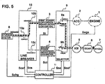
- FIG. 5 illustrates an acceleration operation when failure occurs to the second power conversion means (DC/AC converter) 4 and the amount of charge of the storage system 8 is sufficient.
- the controller 11 outputs a demand Seg to the engine 1 based on the state of charge signal Schg from the storage system 8 until the storage system 8 is at a state of charge capable of accelerating the railway car, and outputs a converter control demand Sc to the first power conversion means (AC/DC converter) 3.
- the storage unit 8 can be charged via the route illustrated by the dashed arrow line of FIG. 4 connecting the engine 1, the AC generator 2, the selector 9a, the fist power conversion means (AC/DC converter) 3, the line breaker 10b, the line breaker 10a and the storage system 8.
- the line breaker 10c is set to "disconnect", and a DC/AC converter no-control demand Soi is output to the second power conversion means (DC/AC converter) 4 so that the second power conversion means (DC/AC converter) 4 will not operate.
- the controller 11 switches the selector switch 9a to a "failed" side via a demand Sse.
- the controller 11 outputs a DC/AC converter control demand Si to the first power conversion means (AC/DC converter) 3 and drives the AC tractionmotor 5.
- the controller 11 outputs a demand Segs to the engine 1 and brings the engine to either a stop or an idling state.
- the accumulated energy in the storage system 8 is converted to tractive effort of the wheels 7 to accelerate the railway car in the route illustrated by the dashed arrow line of FIG. 5 connecting the storage system 8, the line breaker 10a, the line breaker 10b, the first power conversion means (DC/AC converting operation) 3, the selector 9a, the AC traction motor 5, the gear 6 and the wheel 7.
- the amount of charge of the storage system 8 is gradually reduced by the accelerating operation, and at some point of time the acceleration becomes impossible, but if further accelerating is necessary, charging of the storage system 8 is performed via the operation illustrated in FIG. 4 , according to which further acceleration becomes possible.
- the second power conversion means (DC/AC converter) 4 even if failure occurs to the second power conversion means (DC/AC converter) 4, standstill of the railway car can be prevented by using the first power conversion means (AC/DC converter) 3 to perform either AC/DC converting operation or DC/AC converting operation.
- FIG. 6 illustrates a charging operation of the storage system when failure occurs to the first power conversion means (AC/DC converter) 3 in FIG. 3 and the amount of charge of the storage system 8 is insufficient.
- FIG. 7 illustrates an accelerating operation when failure occurs to the first power conversion means (AC/DC converter) 3 in FIG. 3 when the state of charge of the storage system 8 is sufficient.
- the controller 11 switches the selector switch 9a to a "failed" side when the state of charge of the storage system 8 reaches a state where acceleration of the railway car is possible based on the state of charge signal Schg from the storage system 8, outputs a demand Seg to the engine 1, and outputs a converter control demand Sc to the second power conversion means (DC/AC converter) 4.
- the storage system 8 is charged via the route shown by the dashed arrow line of FIG. 6 connecting the engine 1, the AC generator 2, the selector 9a, the second power conversion means (AC/DC converting operation) 4, the line breaker 10c, the line breaker 10a and the storage system 8.
- the line breaker 10b is set to "disconnect", and an AC/DC converter no-control demand Soc is output to the first power conversion means (AC/DC converter) 3 so that the first power conversion means (AC/DC converter) 3 will not operate.
- the controller 11 switches the selector switch 9a to "normal" side based on demand Sse.
- the controller 11 outputs a DC/AC control demand Si to the second power conversion means (DC/AC converting operation) 4, and drives the AC traction motor 5.
- the controller 11 outputs a demand Segs to the engine 1, and brings the engine to a stop or an idling state.
- the accumulated energy in the storage system 8 is converted to tractive effort of the wheels 7 to accelerate the railway car in the route illustrated by the dashed arrow line of FIG. 7 connecting the storage system 8, the line breaker 10a, the line breaker 10c, the second power conversion means (DC/AC converting operation) 4, the selector 9b, the AC traction motor 5, the gear 6 and the wheel 7.
- the amount of charge of the storage system 8 is gradually reduced by the accelerating operation, and at some point of time the acceleration becomes impossible, but if further acceleration is necessary, charging of the storage system 8 is performed by the operation illustrated in FIG. 6 , according to which further acceleration becomes possible.
- the second power conversion means (DC/AC converter) 4 can be prevented by using the second power conversion means (DC/AC converter) 4 to perform either AC/DC converting operation or DC/AC converting operation.
- the healthy-operating power conversion means can be switched and used to perform both charging operation of the storage system via an AC/DC converting operation and an accelerating operation via a DC/AC converting operation, to thereby enable continuous self-running operation of the railway car.
- the healthy-operating power conversion means can be used to stop the DC/AC conversion operation and to perform AC/DC conversion operation to charge the storage system, so as to suppress the delay in train operation.
- FIG. 8 shows a second embodiment of the traction system of a railway car according to the present invention.
- the engine 1 and the AC generator 2 of the embodiment illustrated in FIG. 3 is replaced with a current collector 13 and a voltage transformer 12.
- the present invention can be applied to an electric train system obtaining power via a catenary and third rail, wherein when failure occurs to either the first power conversion means (AC/DC converter) 3 or the second power conversion means (DC/AC converter) 4, the healthy-operating power conversion means of either the first power conversion means (AC/DC converter) 3 or the second power conversion means (DC/AC converter) 4 is used to perform AC/DC converting operation or DC/AC converting operation, so as to prevent standstill of the railway car.
Landscapes
- Engineering & Computer Science (AREA)
- Transportation (AREA)
- Mechanical Engineering (AREA)
- Power Engineering (AREA)
- Life Sciences & Earth Sciences (AREA)
- Sustainable Development (AREA)
- Sustainable Energy (AREA)
- Electric Propulsion And Braking For Vehicles (AREA)
- Hybrid Electric Vehicles (AREA)
Abstract
Description
- The present invention relates to a traction system of railway cars, and specifically, relates to the art of driving electric trains by converting AC power to DC power and reconverting the DC power to AC power.
- In railway cars traveling onAC-electrified railroad tracks, it is common to adopt a system in which AC power received from a catenary or third rail is converted via an AC/DC converter to DC power, which is then converted via a DC/AC converter into AC power to drive an AC traction motor.
FIG. 9 shows a basic configuration of a traction system of an electric train adopting a common traction converter. The AC power entered via acurrent collector 13 is either reduced or boosted up to predetermined voltage via avoltage transformer 12, and converted via a first power conversion means (AC/DC converter) 3 to DC power. The DC power is then converted via a second power conversion means (DC/AC converter) 4 to AC power, which drives anAC traction motor 5 for rotatingwheels 7 via agear 6 to thereby accelerate the railway car. - Further, with respect to the system illustrated in
FIG. 9 , a traction system of a railway car capable of running on non-electrified routes is also considered, wherein the railway car is equipped with an engine and an AC generator instead of thecurrent collector 13 and thevoltage transformer 12, which is capable of obtaining AC power via the generator driven by the engine. - If the prior art traction converter system illustrated in
FIG. 9 is applied to railway cars running on local routes or the like which do not require large transporting capacities, one traction converter should be sufficient per train. However, when such system is adopted, if failure occurs to the AC/DC converter or the DC/AC converter, the train can no longer run by itself, and when such failure occurs to the train on a route in service, the diagram of train operation will be disturbed greatly when the failed car stops to operate. Further, if the car comes to a standstill in a tunnel or on a bridge, it becomes impossible to unload the passengers from the cars, and other problems will occur from the viewpoint of safety. - The above-mentioned problem can be solved by enhancing the redundancy of the system by decentralizing AC/DC converters and DC/AC converters, but such configuration causes significant increase of cost and size of the system, and in some cases, it is impossible to secure the installation space for components, so it was difficult to realize such redundant system.
- The present invention provides a traction system of a railway car having a traction converter, capable of running independently by itself without causing a standstill even when failure occurs to either the AC/DC converter or the DC/AC converter, thereby enabling to minimize the disturbance of diagram of the train operation.
- The present invention is realized by a traction system of a railway car having a traction converter, comprising a storage system connected to a DC link between an AC/DC converter and a DC/AC converter, and a selector for switching an AC-side circuit of the AC/DC converter and the DC/AC converter, wherein if either one of the AC/DC converter or the DC/AC converter fails, the healthy AC/DC converter or the DC/AC converter is operated as converter to store energy in the storage system, wherein when a demand to accelerate the railway car is provided, the healthy one of the AC/DC converter or the DC/AC converter is operated as DC/AC converter, in order to drive the AC traction motor by using the stored energy.
- As described, the present invention provides a traction converter system capable of driving a railway car via combination of a first power conversion means (AC/DC converter) and a second powerconversionmeans (DC/AC converter), wherein even if failure occurs to either one of the first power conversion means (AC/DC converter) or the second power conversion means (DC/AC converter), the healthy-operating power conversion means is used to selectively perform a charging operation of the storage system via an AC/DC converting operation and an accelerating operation via a DC/AC converting operation, to thereby continue self-running operation of the railway car. As a result, it becomes possible to minimize the disturbance of the train operation diagram when failure occurs to the system, and to prevent standstill of the train in tunnels or on bridges, thereby providing a safe traction system of railway cars.
-
-
FIG. 1 shows a basic configuration of a traction system of a railway car according to a first embodiment of the present invention; -
FIG. 2 shows a configuration of a controller according to the first embodiment of the present invention; -
FIG. 3 is an explanatory view of a normal accelerating operation according to the first embodiment of the present invention; -
FIG. 4 is an explanatory view of a charging operation for charging a storage system when failure of DC/AC converter occurs according to the first embodiment of the present invention; -
FIG. 5 is an explanatory view of an acceleration operation when failure of DC/AC converter occurs according to the first embodiment of the present invention; -
FIG. 6 is an explanatory view of a charging operation for charging a storage system when failure of AC/DC converter occurs according to the first embodiment of the present invention; -
FIG. 7 is an explanatory view of an acceleration operation when failure of AC/DC converter occurs according to the first embodiment of the present invention; -
FIG. 8 illustrates a second embodiment of the preset invention; and -
FIG. 9 is a view showing the basic configuration of an electric car according to the prior art. - Now, the preferred embodiments of a traction system of a railway car according to the present invention will be described with reference to the drawings.
-
FIG. 1 is a view showing the basic configuration of a first preferred embodiment of the present invention in a traction system of a railway car according to the present invention. The present traction system of a railway car is composed of anengine 1, anAC generator 2 driven by theengine 1, aselector 9, a first power conversion means 3 capable of mutually converting AC power and DC power and normally operating as anAC/DC converter, a second power conversion means 4 capable of mutually converting AC power and DC power and normally operating as a DC/AC converter, anAC traction motor 5, agear 6,wheels 7 and astorage system 8. - The
engine 1 outputs a torque based on a demand from a control system not shown. TheAC generator 2 receives the torque fromengine 1, converts this mechanical power into AC electric power. Theselector 9 normally connects theAC generator 2 to the input of the first power conversion means (AC/DC converter) 3. The first power conversion means (AC/DC converter) 3 receives input of the AC power output from theAC generator 2, converts the same into DC power and outputs the same. The second power conversion means (DC/AC converter) 4 receives input of the DC power output from the first power conversion means (AC/DC converter) 3, converts the same into AC power and outputs the same. Theselector 9 normally connects anAC traction motor 5 to the output of the second power conversion means (DC/AC converter) 4. TheAC traction motor 5 receives input of the AC power output from the second power conversion means (DC/AC converter) 4, converts the same into torque and outputs the same. Thegear 6 amplifies the torque output of theAC traction motor 5 by reducing the number of rotations and outputs the same to drive thewheels 7 and to accelerate or decelerate the railway car. - The
storage system 8 is connected so as to receive input of DC power from a DC link between the first power conversion means (AC/DC converter) 3 and the second power conversion means (DC/AC converter) 4, or to output DC power to the DC link between the first power conversion means (AC/DC converter) 3 and the second power conversion means (DC/AC converter) 4. The following operation is made possible by this configuration. - If an acceleration demand is provided to the railway car when the system is normal, the AC power obtained via the
engine 1 and thegenerator 2 is converted into DC power via the first power conversion means 3 operating as an AC/DC converter. The second power conversion means 4 operating as a DC/AC converter outputs AC power based on the above-mentioned DC power and the DC power stored in thestorage system 8, so as to drive theAC traction motor 5 and provide tractive effort to thewheels 7 via thegear 6. - On the other hand, when a deceleration demand is provided to the railway car, the
AC tractionmotor 5 is operated as generator, and the generated AC power is converted to DC power by operating the second power conversion means 4 as an AC/DC converter. The DC power is either recovered in thestorage system 8 or converted into AC power by operating the first power conversion means 3 as a DC/AC converter, and theAC generator 2 is operated as a motor so as to drive the engine from the generator side to activate an engine brake, by which thewheels 7 obtain braking effort and the railway car decelerates. - Next, we will describe an operation corresponding to the case where failure occurs to the first power conversion means (AC/DC converter) 3 or the second power conversion means (DC/AC converter) 4.
- In
FIG. 1 , normally, the first power conversion means 3 operating as an AC/DC converter and the second power conversion means 4 operating as a DC/AC converter are respectively connected via theselector 9 to theAC generator 2 and theAC traction motor 5. When failure occurs to either the first power conversion means (AC/DC converter) 3 or the second power conversion means (DC/AC converter) 4 (at time of failure), theselector 9 is operated, and theAC traction motor 5 is connected to the first power conversion means 3 and theAC generator 2 is connected to the second power conversion means 4. Since the first power conversion means 3 and the second power conversion means 4 can have both function as an AC/DC converter and a DC/AC converter, when failure occurs to either the first power conversion means 3 or the second power conversion means 4, the healthy-operating power conversion means is connected to theAC generator 2, which is used as an AC/DC converter to charge thestorage system 8. When an acceleration demand is provided to the railway car, the healthy-operating power conversion means is connected to theAC traction motor 5, which is operated as a DC/AC converter to drive theAC traction motor 5 via the energy stored in thestorage system 8 so as to accelerate the railway car. -
FIG. 2 is a view showing the configuration of a controller according to the first embodiment of the present invention. Theengine 1 outputs a torque based on a demand Seg from acontroller 11. TheAC generator 2 receives the torque from theengine 1, converts this mechanical power into AC electric power. - The
selector 9 is composed of two sets ofselectors controller 11. Thecontroller 11 monitors a status signal Ssef of theselector 9, and performs selection of various control operations after confirming that the switching operation has been completed. During normal operation, an AC/DC converter control demand Sc is provided to the first power conversion means (AC/DC converter) 3, wherein the first power conversion means (AC/DC converter) 3 receives the AC power output from theAC generator 2 as input, converts the same into DC power and outputs the same. - A control demand Si is provided to the second power conversion means (DC/AC converter) 4, wherein the second power conversion means (DC/AC converter) 4 receives DC power obtained from the first power conversion means (AC/DC converter) 3 and the
storage system 8 as input, converts the same into AC power and outputs the same. - The
AC traction motor 5 receives the AC power output from the second power conversion means (DC/AC converter) 4 as input, converts the same into torque and outputs the same. Thegear 6 amplifies the torque output of theAC tractionmotor 5 by reducing the number of rotations and outputs the same, so as to drive theaxles 7 and accelerate or decelerate the railway car. - The
controller 11 controls the system based on a state of charge signal Schg of thestorage system 8. It is also possible to obtain the state of storage from the input/output current of the storage system and the DC link voltage, instead of the state of charge signal Schg of the storage system. - A
line breaker 10 is provided for disconnecting the circuit between the first power conversion means (AC/DC converter) 3, the second power conversion means (DC/AC converter) 4 and thestorage system 8. When failure occurs to any one of the first power conversion means (AC/DC converter) 3, the second power conversion means (DC/AC converter) 4 or thepower storage system 8, the line breaker connected to that failed device can be disconnected based on a line breaker operation demand Scs from the controller. Thecontroller 11 monitors the status signal Scsf of the line breaker and controls the system. Further, inFIG. 2 , theselectors AC traction motor 5. Further, theselectors selector 9 can be omitted. - Now, we will describe an example of the actual operation according to the present invention.
FIG. 3 is a view showing the state according to the configuration ofFIG. 2 in which the railway car is performing a normal accelerating operation. InFIG. 3 , theselector 9a is at "normal" position, and the AC power obtained from theengine 1 and theAC generator 2 is entered to the first power conversion means (AC/DC converter) 3. All the line breakers are at "connect" state, and the DC power converted via the first power conversion means (AC/DC converter) 3 is entered to the second power conversion means (DC/AC converter) 4, where it is reconverted to AC power. - Further, if the power necessary to accelerate the railway car cannot be sufficiently obtained from the DC power output from the first power conversion means (AC/DC converter) 3, DC power is complemented from the
storage system 8. Theselector 9b is at "normal" position, and the AC power output from the second power conversion means (DC/AC converter) 4 is output to theAC traction motor 5, and theAC traction motor 5 drives thewheels 7 via thegear 6 to accelerate the railway car. - Next, we will describe the operation to be performed when failure occurs to the first power conversion means (AC/DC converter) 3 or the second power conversion means (DC/AC converter) 4.
- At first, the operation when failure occurs to the second power conversion means (DC/AC converter) 4 in
FIG. 3 will be described with reference toFIGS. 4 and5 .FIG. 4 illustrates a charging operation of the storage system when failure occurs to the second power conversion means (DC/AC converter) 4 inFIG. 3 and the amount of charge of thestorage system 8 is at an insufficient state.FIG. 5 illustrates an acceleration operation when failure occurs to the second power conversion means (DC/AC converter) 4 and the amount of charge of thestorage system 8 is sufficient. - In
FIG. 4 , thecontroller 11 outputs a demand Seg to theengine 1 based on the state of charge signal Schg from thestorage system 8 until thestorage system 8 is at a state of charge capable of accelerating the railway car, and outputs a converter control demand Sc to the first power conversion means (AC/DC converter) 3. As a result, thestorage unit 8 can be charged via the route illustrated by the dashed arrow line ofFIG. 4 connecting theengine 1, theAC generator 2, theselector 9a, the fist power conversion means (AC/DC converter) 3, theline breaker 10b, theline breaker 10a and thestorage system 8. At this time, theline breaker 10c is set to "disconnect", and a DC/AC converter no-control demand Soi is output to the second power conversion means (DC/AC converter) 4 so that the second power conversion means (DC/AC converter) 4 will not operate. - In
FIG. 5 , when an acceleration demand is provided to the railway car when thestorage system 8 is at a state of charge sufficient to accelerate the railway car, thecontroller 11 switches theselector switch 9a to a "failed" side via a demand Sse. Next, thecontroller 11 outputs a DC/AC converter control demand Si to the first power conversion means (AC/DC converter) 3 and drives theAC tractionmotor 5. At this time, thecontroller 11 outputs a demand Segs to theengine 1 and brings the engine to either a stop or an idling state. As a result, the accumulated energy in thestorage system 8 is converted to tractive effort of thewheels 7 to accelerate the railway car in the route illustrated by the dashed arrow line ofFIG. 5 connecting thestorage system 8, theline breaker 10a, theline breaker 10b, the first power conversion means (DC/AC converting operation) 3, theselector 9a, theAC traction motor 5, thegear 6 and thewheel 7. - The amount of charge of the
storage system 8 is gradually reduced by the accelerating operation, and at some point of time the acceleration becomes impossible, but if further accelerating is necessary, charging of thestorage system 8 is performed via the operation illustrated inFIG. 4 , according to which further acceleration becomes possible. As described, according toFIG. 3 , even if failure occurs to the second power conversion means (DC/AC converter) 4, standstill of the railway car can be prevented by using the first power conversion means (AC/DC converter) 3 to perform either AC/DC converting operation or DC/AC converting operation. - Next, with reference to
FIGS. 6 and7 , the operation when failure occurs to the first power conversion means (AC/DC converter) 3 inFIG. 3 will be described.FIG. 6 illustrates a charging operation of the storage system when failure occurs to the first power conversion means (AC/DC converter) 3 inFIG. 3 and the amount of charge of thestorage system 8 is insufficient.FIG. 7 illustrates an accelerating operation when failure occurs to the first power conversion means (AC/DC converter) 3 inFIG. 3 when the state of charge of thestorage system 8 is sufficient. - In
FIG. 6 , thecontroller 11 switches theselector switch 9a to a "failed" side when the state of charge of thestorage system 8 reaches a state where acceleration of the railway car is possible based on the state of charge signal Schg from thestorage system 8, outputs a demand Seg to theengine 1, and outputs a converter control demand Sc to the second power conversion means (DC/AC converter) 4. As a result, thestorage system 8 is charged via the route shown by the dashed arrow line ofFIG. 6 connecting theengine 1, theAC generator 2, theselector 9a, the second power conversion means (AC/DC converting operation) 4, theline breaker 10c, theline breaker 10a and thestorage system 8. At this time, theline breaker 10b is set to "disconnect", and an AC/DC converter no-control demand Soc is output to the first power conversion means (AC/DC converter) 3 so that the first power conversion means (AC/DC converter) 3 will not operate. - In
FIG. 7 , when a demand to accelerate the railway car is provided when thestorage system 8 is at a state of charge sufficient to accelerate the railway car, thecontroller 11 switches theselector switch 9a to "normal" side based on demand Sse. Next, thecontroller 11 outputs a DC/AC control demand Si to the second power conversion means (DC/AC converting operation) 4, and drives theAC traction motor 5. Further, thecontroller 11 outputs a demand Segs to theengine 1, and brings the engine to a stop or an idling state. As a result, the accumulated energy in thestorage system 8 is converted to tractive effort of thewheels 7 to accelerate the railway car in the route illustrated by the dashed arrow line ofFIG. 7 connecting thestorage system 8, theline breaker 10a, theline breaker 10c, the second power conversion means (DC/AC converting operation) 4, theselector 9b, theAC traction motor 5, thegear 6 and thewheel 7. - The amount of charge of the
storage system 8 is gradually reduced by the accelerating operation, and at some point of time the acceleration becomes impossible, but if further acceleration is necessary, charging of thestorage system 8 is performed by the operation illustrated inFIG. 6 , according to which further acceleration becomes possible. As described, according toFIG. 3 , even if failure occurs to the first power conversion means (AC/DC converter) 3, standstill of the railway car can be prevented by using the second power conversion means (DC/AC converter) 4 to perform either AC/DC converting operation or DC/AC converting operation. - As described, according to the present invention, even if failure occurs to either the first power conversion means (AC/DC converter) or the second power conversion means (DC/AC converter), the healthy-operating power conversion means can be switched and used to perform both charging operation of the storage system via an AC/DC converting operation and an accelerating operation via a DC/AC converting operation, to thereby enable continuous self-running operation of the railway car.
- In the actual operation of the railway car, by performing the charging operation of the storage system illustrated in
FIG. 4 orFIG. 6 while the railway car is at a stopped state or is coasting, it becomes possible to minimize the delay of the train operation from the diagram and to suppress the disruption of train operation. - Further, even if an acceleration demand is provided, if the amount of charge of the storage system is reduced to a revel where no further acceleration operation is impossible, the healthy-operating power conversion means can be used to stop the DC/AC conversion operation and to perform AC/DC conversion operation to charge the storage system, so as to suppress the delay in train operation.
-
FIG. 8 shows a second embodiment of the traction system of a railway car according to the present invention. Theengine 1 and theAC generator 2 of the embodiment illustrated inFIG. 3 is replaced with acurrent collector 13 and avoltage transformer 12. The present invention can be applied to an electric train system obtaining power via a catenary and third rail, wherein when failure occurs to either the first power conversion means (AC/DC converter) 3 or the second power conversion means (DC/AC converter) 4, the healthy-operating power conversion means of either the first power conversion means (AC/DC converter) 3 or the second power conversion means (DC/AC converter) 4 is used to perform AC/DC converting operation or DC/AC converting operation, so as to prevent standstill of the railway car.
Claims (3)
- A traction system of a railway car comprising an AC generator means driven by an engine, a first power conversion means connected to the AC generator means and capable of mutually converting power between AC power and DC power, an AC traction motor, a second power conversion means connected to the AC traction motor and capable of mutually converting power between AC power and DC power, a selector for mutually switching an AC-side device of the two power conversion means, and a storage system connected to a DC-side of the two power conversion means, wherein the system comprises a function to store energy in the storage system via a healthy-operating power conversion means when either one of the two power conversion means fails, and to drive the AC traction motor using the stored energy.
- A traction system of a railway car comprising a current collector for collecting AC power from a catenary or third rail, a first power conversion means connected to the current collector and capable of mutually converting power between AC power and DC power, an AC traction motor, a second power conversion means connected to the AC traction motor and capable of mutually converting power between AC power and DC power, a selector for mutually switching an AC-side device of the two power conversion means, and a storage system connected to a DC-side of the two power conversion means, wherein
the system comprises a function to store energy in the storage system via a healthy-operating power conversionmeans when either one of the two power conversion means fails, and to drive the AC traction motor using the stored energy. - The traction system of a railway car according to claim 1 or claim 2, wherein switching between the function to store energy in the storage system via the healthy-operating power conversion means when either one of the two power conversion means fails and the function to drive the traction motor using the stored energy is performed based on a state of charge of the storage system or an operating demand provided to the railway car.
Applications Claiming Priority (1)
| Application Number | Priority Date | Filing Date | Title |
|---|---|---|---|
| JP2008095081A JP5017163B2 (en) | 2008-04-01 | 2008-04-01 | Railway vehicle drive system |
Publications (3)
| Publication Number | Publication Date |
|---|---|
| EP2106954A2 true EP2106954A2 (en) | 2009-10-07 |
| EP2106954A3 EP2106954A3 (en) | 2014-01-08 |
| EP2106954B1 EP2106954B1 (en) | 2015-07-22 |
Family
ID=40912004
Family Applications (1)
| Application Number | Title | Priority Date | Filing Date |
|---|---|---|---|
| EP09250503.1A Not-in-force EP2106954B1 (en) | 2008-04-01 | 2009-02-25 | Traction system of railway car |
Country Status (4)
| Country | Link |
|---|---|
| EP (1) | EP2106954B1 (en) |
| JP (1) | JP5017163B2 (en) |
| KR (1) | KR101075641B1 (en) |
| CN (1) | CN101549650B (en) |
Cited By (9)
| Publication number | Priority date | Publication date | Assignee | Title |
|---|---|---|---|---|
| EP2662978A1 (en) * | 2012-05-09 | 2013-11-13 | Hamilton Sundstrand Corporation | Fault tolerant DC power systems |
| US8629644B2 (en) | 2010-11-16 | 2014-01-14 | Hamilton Sundstrand Corporation | Fault tolerant DC power systems |
| US8786116B2 (en) | 2010-08-26 | 2014-07-22 | Mitsubishi Electric Corporation | Vehicle control device and diesel hybrid vehicle system |
| EP2368744A3 (en) * | 2010-03-23 | 2015-08-05 | Hitachi, Ltd. | Traction system for trainset |
| EP2810813A4 (en) * | 2012-01-30 | 2015-12-16 | Mitsubishi Electric Corp | DEVICE FOR CONTROLLING THE PROPULSION OF AN ELECTRIC VEHICLE AND METHOD FOR CONTROLLING THE DEVICE |
| US9346363B2 (en) | 2012-08-13 | 2016-05-24 | Mitsubishi Electric Corporation | Propulsion control apparatus of engine hybrid railroad vehicle |
| EP3038854A4 (en) * | 2013-08-29 | 2017-04-19 | Kabushiki Kaisha Toshiba | Electric power conversion device, emergency traveling system and railway vehicle |
| EP3213953A1 (en) * | 2016-03-04 | 2017-09-06 | Kabushiki Kaisha Toshiba | Hybrid electric locomotive |
| EP3696005A4 (en) * | 2017-10-13 | 2021-07-14 | Hitachi, Ltd. | DRIVE CONTROL DEVICE AND DEFINED TRAIN MOUNTED WITH LEDIT DRIVE CONTROL DEVICE |
Families Citing this family (8)
| Publication number | Priority date | Publication date | Assignee | Title |
|---|---|---|---|---|
| AU2010312524A1 (en) * | 2009-10-27 | 2012-05-24 | Hitachi Construction Machinery Co., Ltd. | Electric drive vehicle |
| JP5605061B2 (en) * | 2010-08-02 | 2014-10-15 | 富士電機株式会社 | Electric vehicle drive circuit |
| JP5253591B2 (en) * | 2012-02-01 | 2013-07-31 | 三菱電機株式会社 | Vehicle control device and diesel hybrid vehicle system |
| DE102012206864A1 (en) * | 2012-04-25 | 2013-10-31 | Siemens Aktiengesellschaft | Electric rail vehicle and procedure for its operation |
| JP6106729B1 (en) * | 2015-09-29 | 2017-04-05 | 富士重工業株式会社 | Vehicle power supply device and fault diagnosis method thereof |
| EP3489068B1 (en) * | 2016-07-19 | 2025-08-13 | Hitachi, Ltd. | Vehicle power conversion device and rail vehicle |
| CN111532146B (en) * | 2020-04-24 | 2024-05-31 | 北京北交新能科技有限公司 | Non-net self-walking energy storage and unidirectional AC/DC converter system for rail transit |
| CN113911146B (en) * | 2021-09-28 | 2022-09-09 | 西安中车永电电气有限公司 | Environment-friendly diesel locomotive alternating current-direct current transmission system |
Family Cites Families (13)
| Publication number | Priority date | Publication date | Assignee | Title |
|---|---|---|---|---|
| JP3171218B2 (en) | 1993-04-30 | 2001-05-28 | 株式会社エクォス・リサーチ | Electric vehicle device |
| KR0183465B1 (en) * | 1993-07-06 | 1999-05-15 | 토니 헬샴 | A regenerating control method for an industrial motor car |
| SE502191C2 (en) * | 1993-09-30 | 1995-09-11 | Asea Brown Boveri | Method and apparatus for compensating the failure of an inverter |
| FR2713565B1 (en) * | 1993-12-13 | 1996-01-19 | Gec Alsthom Transport Sa | High availability multicurrent power system for railway locomotive. |
| DE19610800C1 (en) * | 1996-03-19 | 1997-07-24 | Siemens Ag | Fault-tolerant traction drive converter for rail vehicles |
| JPH09266605A (en) * | 1996-03-28 | 1997-10-07 | Hitachi Ltd | Drive device for hybrid electric vehicle |
| US20060005736A1 (en) * | 2001-03-27 | 2006-01-12 | General Electric Company | Hybrid energy off highway vehicle electric power management system and method |
| JP4056247B2 (en) | 2001-11-27 | 2008-03-05 | 三菱重工業株式会社 | Electric vehicle power supply system |
| JP3924725B2 (en) | 2003-03-14 | 2007-06-06 | 株式会社日立製作所 | Railway vehicle drive system |
| JP2006087299A (en) * | 2005-11-04 | 2006-03-30 | Toshiba Corp | Electric vehicle controller |
| JP2006074998A (en) | 2005-11-07 | 2006-03-16 | Hitachi Ltd | Railway vehicle |
| JP4929689B2 (en) | 2005-11-18 | 2012-05-09 | 株式会社日立製作所 | Control method of hybrid vehicle and prime mover |
| JP4907262B2 (en) * | 2006-08-23 | 2012-03-28 | 株式会社日立製作所 | Electric vehicle control device |
-
2008
- 2008-04-01 JP JP2008095081A patent/JP5017163B2/en not_active Expired - Fee Related
-
2009
- 2009-02-16 KR KR1020090012201A patent/KR101075641B1/en not_active Expired - Fee Related
- 2009-02-25 EP EP09250503.1A patent/EP2106954B1/en not_active Not-in-force
- 2009-02-26 CN CN200910008361XA patent/CN101549650B/en not_active Expired - Fee Related
Cited By (12)
| Publication number | Priority date | Publication date | Assignee | Title |
|---|---|---|---|---|
| EP2368744A3 (en) * | 2010-03-23 | 2015-08-05 | Hitachi, Ltd. | Traction system for trainset |
| US8786116B2 (en) | 2010-08-26 | 2014-07-22 | Mitsubishi Electric Corporation | Vehicle control device and diesel hybrid vehicle system |
| US8629644B2 (en) | 2010-11-16 | 2014-01-14 | Hamilton Sundstrand Corporation | Fault tolerant DC power systems |
| EP2810813A4 (en) * | 2012-01-30 | 2015-12-16 | Mitsubishi Electric Corp | DEVICE FOR CONTROLLING THE PROPULSION OF AN ELECTRIC VEHICLE AND METHOD FOR CONTROLLING THE DEVICE |
| EP2662978A1 (en) * | 2012-05-09 | 2013-11-13 | Hamilton Sundstrand Corporation | Fault tolerant DC power systems |
| US9346363B2 (en) | 2012-08-13 | 2016-05-24 | Mitsubishi Electric Corporation | Propulsion control apparatus of engine hybrid railroad vehicle |
| EP2883740A4 (en) * | 2012-08-13 | 2016-06-15 | Mitsubishi Electric Corp | HYBRID MOTOR VEHICLE VEHICLE PROPULSION CONTROL DEVICE |
| EP3038854A4 (en) * | 2013-08-29 | 2017-04-19 | Kabushiki Kaisha Toshiba | Electric power conversion device, emergency traveling system and railway vehicle |
| EP3213953A1 (en) * | 2016-03-04 | 2017-09-06 | Kabushiki Kaisha Toshiba | Hybrid electric locomotive |
| CN107150694A (en) * | 2016-03-04 | 2017-09-12 | 株式会社东芝 | Hybrid power electric locomotive |
| CN107150694B (en) * | 2016-03-04 | 2019-07-05 | 株式会社东芝 | Hybrid power electric locomotive |
| EP3696005A4 (en) * | 2017-10-13 | 2021-07-14 | Hitachi, Ltd. | DRIVE CONTROL DEVICE AND DEFINED TRAIN MOUNTED WITH LEDIT DRIVE CONTROL DEVICE |
Also Published As
| Publication number | Publication date |
|---|---|
| KR20090105803A (en) | 2009-10-07 |
| JP2009254013A (en) | 2009-10-29 |
| CN101549650A (en) | 2009-10-07 |
| EP2106954A3 (en) | 2014-01-08 |
| JP5017163B2 (en) | 2012-09-05 |
| EP2106954B1 (en) | 2015-07-22 |
| KR101075641B1 (en) | 2011-10-21 |
| CN101549650B (en) | 2012-06-06 |
Similar Documents
| Publication | Publication Date | Title |
|---|---|---|
| EP2106954B1 (en) | Traction system of railway car | |
| JP7421879B2 (en) | vehicle propulsion system | |
| AU2012212816B2 (en) | Driving system, driving system for railroad-vehicle, and railroad-vehicle and multi-car train mounted with same | |
| CN102958746B (en) | Propulsion control devices for trams, and rail vehicle systems | |
| JP5801999B2 (en) | Train trains equipped with railway on-board electrical equipment | |
| EP3038854B1 (en) | Electric power conversion device, emergency traveling system and railway vehicle | |
| CN101837740B (en) | Railway system installing power supply facility on railroads between stations | |
| US9145060B2 (en) | Propulsion control apparatus for electric motor car | |
| JP7698656B2 (en) | Vehicle with electric traction including an energy management system and method for managing energy in a vehicle with such electric traction - Patent application | |
| RU2714800C1 (en) | Electric railway vehicle drive system and vehicle drive method | |
| US20150343906A1 (en) | Propulsion control apparatus for railroad vehicle | |
| EP2689983B2 (en) | Drive system and railway vehicle provided with the drive system | |
| CN104080639A (en) | Tram propulsion control device and control method thereof | |
| CN101448670A (en) | Tram control device | |
| JP5281372B2 (en) | Electric railway vehicle drive system | |
| JP5851925B2 (en) | Electric railway vehicle drive system | |
| CN111890945A (en) | Traction control system of medium-high speed maglev train | |
| JP2012178898A (en) | Drive system for railway vehicle, railway vehicle, and train organization including the railway vehicle | |
| JP2015223053A (en) | Vehicle for maintenance | |
| US11034247B2 (en) | Vehicle propulsion system | |
| JP5394665B2 (en) | Railway vehicle drive system | |
| JP2005051891A (en) | Feeder, train organization and towed vehicle | |
| JP2012125128A (en) | Storage battery type vehicle | |
| JP2023132548A (en) | Charging device for storage battery vehicles and charging system for storage battery vehicles | |
| KR20260015069A (en) | Dual Motor Propulsion Apparatus For Railway Vehicle and Control Method Therefor |
Legal Events
| Date | Code | Title | Description |
|---|---|---|---|
| PUAI | Public reference made under article 153(3) epc to a published international application that has entered the european phase |
Free format text: ORIGINAL CODE: 0009012 |
|
| 17P | Request for examination filed |
Effective date: 20090313 |
|
| AK | Designated contracting states |
Kind code of ref document: A2 Designated state(s): AT BE BG CH CY CZ DE DK EE ES FI FR GB GR HR HU IE IS IT LI LT LU LV MC MK MT NL NO PL PT RO SE SI SK TR |
|
| AX | Request for extension of the european patent |
Extension state: AL BA RS |
|
| PUAL | Search report despatched |
Free format text: ORIGINAL CODE: 0009013 |
|
| AK | Designated contracting states |
Kind code of ref document: A3 Designated state(s): AT BE BG CH CY CZ DE DK EE ES FI FR GB GR HR HU IE IS IT LI LT LU LV MC MK MT NL NO PL PT RO SE SI SK TR |
|
| AX | Request for extension of the european patent |
Extension state: AL BA RS |
|
| RIC1 | Information provided on ipc code assigned before grant |
Ipc: B60L 11/14 20060101ALI20131202BHEP Ipc: B60L 11/08 20060101AFI20131202BHEP Ipc: B60L 11/12 20060101ALI20131202BHEP Ipc: B60L 11/18 20060101ALI20131202BHEP Ipc: B60L 9/28 20060101ALI20131202BHEP Ipc: B60L 3/04 20060101ALI20131202BHEP Ipc: B60L 3/00 20060101ALI20131202BHEP |
|
| AKX | Designation fees paid |
Designated state(s): AT BE BG CH CY CZ DE DK EE ES FI FR GB GR HR HU IE IS IT LI LT LU LV MC MK MT NL NO PL PT RO SE SI SK TR |
|
| RIC1 | Information provided on ipc code assigned before grant |
Ipc: B60L 11/12 20060101ALI20141111BHEP Ipc: B60L 3/04 20060101ALI20141111BHEP Ipc: B60L 11/14 20060101ALI20141111BHEP Ipc: B60L 9/28 20060101ALI20141111BHEP Ipc: B60L 3/00 20060101ALI20141111BHEP Ipc: B60L 11/08 20060101AFI20141111BHEP Ipc: B60L 11/18 20060101ALI20141111BHEP |
|
| GRAP | Despatch of communication of intention to grant a patent |
Free format text: ORIGINAL CODE: EPIDOSNIGR1 |
|
| INTG | Intention to grant announced |
Effective date: 20141223 |
|
| GRAS | Grant fee paid |
Free format text: ORIGINAL CODE: EPIDOSNIGR3 |
|
| RAP1 | Party data changed (applicant data changed or rights of an application transferred) |
Owner name: HITACHI, LTD. |
|
| GRAA | (expected) grant |
Free format text: ORIGINAL CODE: 0009210 |
|
| AK | Designated contracting states |
Kind code of ref document: B1 Designated state(s): AT BE BG CH CY CZ DE DK EE ES FI FR GB GR HR HU IE IS IT LI LT LU LV MC MK MT NL NO PL PT RO SE SI SK TR |
|
| REG | Reference to a national code |
Ref country code: GB Ref legal event code: FG4D |
|
| REG | Reference to a national code |
Ref country code: CH Ref legal event code: EP |
|
| REG | Reference to a national code |
Ref country code: IE Ref legal event code: FG4D |
|
| REG | Reference to a national code |
Ref country code: AT Ref legal event code: REF Ref document number: 737676 Country of ref document: AT Kind code of ref document: T Effective date: 20150815 |
|
| REG | Reference to a national code |
Ref country code: DE Ref legal event code: R096 Ref document number: 602009032319 Country of ref document: DE |
|
| REG | Reference to a national code |
Ref country code: AT Ref legal event code: MK05 Ref document number: 737676 Country of ref document: AT Kind code of ref document: T Effective date: 20150722 |
|
| REG | Reference to a national code |
Ref country code: LT Ref legal event code: MG4D |
|
| REG | Reference to a national code |
Ref country code: NL Ref legal event code: MP Effective date: 20150722 |
|
| PG25 | Lapsed in a contracting state [announced via postgrant information from national office to epo] |
Ref country code: LV Free format text: LAPSE BECAUSE OF FAILURE TO SUBMIT A TRANSLATION OF THE DESCRIPTION OR TO PAY THE FEE WITHIN THE PRESCRIBED TIME-LIMIT Effective date: 20150722 Ref country code: FI Free format text: LAPSE BECAUSE OF FAILURE TO SUBMIT A TRANSLATION OF THE DESCRIPTION OR TO PAY THE FEE WITHIN THE PRESCRIBED TIME-LIMIT Effective date: 20150722 Ref country code: NO Free format text: LAPSE BECAUSE OF FAILURE TO SUBMIT A TRANSLATION OF THE DESCRIPTION OR TO PAY THE FEE WITHIN THE PRESCRIBED TIME-LIMIT Effective date: 20151022 Ref country code: GR Free format text: LAPSE BECAUSE OF FAILURE TO SUBMIT A TRANSLATION OF THE DESCRIPTION OR TO PAY THE FEE WITHIN THE PRESCRIBED TIME-LIMIT Effective date: 20151023 Ref country code: LT Free format text: LAPSE BECAUSE OF FAILURE TO SUBMIT A TRANSLATION OF THE DESCRIPTION OR TO PAY THE FEE WITHIN THE PRESCRIBED TIME-LIMIT Effective date: 20150722 |
|
| PG25 | Lapsed in a contracting state [announced via postgrant information from national office to epo] |
Ref country code: SE Free format text: LAPSE BECAUSE OF FAILURE TO SUBMIT A TRANSLATION OF THE DESCRIPTION OR TO PAY THE FEE WITHIN THE PRESCRIBED TIME-LIMIT Effective date: 20150722 Ref country code: PT Free format text: LAPSE BECAUSE OF FAILURE TO SUBMIT A TRANSLATION OF THE DESCRIPTION OR TO PAY THE FEE WITHIN THE PRESCRIBED TIME-LIMIT Effective date: 20151123 Ref country code: PL Free format text: LAPSE BECAUSE OF FAILURE TO SUBMIT A TRANSLATION OF THE DESCRIPTION OR TO PAY THE FEE WITHIN THE PRESCRIBED TIME-LIMIT Effective date: 20150722 Ref country code: IS Free format text: LAPSE BECAUSE OF FAILURE TO SUBMIT A TRANSLATION OF THE DESCRIPTION OR TO PAY THE FEE WITHIN THE PRESCRIBED TIME-LIMIT Effective date: 20151122 Ref country code: HR Free format text: LAPSE BECAUSE OF FAILURE TO SUBMIT A TRANSLATION OF THE DESCRIPTION OR TO PAY THE FEE WITHIN THE PRESCRIBED TIME-LIMIT Effective date: 20150722 Ref country code: AT Free format text: LAPSE BECAUSE OF FAILURE TO SUBMIT A TRANSLATION OF THE DESCRIPTION OR TO PAY THE FEE WITHIN THE PRESCRIBED TIME-LIMIT Effective date: 20150722 Ref country code: ES Free format text: LAPSE BECAUSE OF FAILURE TO SUBMIT A TRANSLATION OF THE DESCRIPTION OR TO PAY THE FEE WITHIN THE PRESCRIBED TIME-LIMIT Effective date: 20150722 |
|
| REG | Reference to a national code |
Ref country code: DE Ref legal event code: R097 Ref document number: 602009032319 Country of ref document: DE |
|
| PG25 | Lapsed in a contracting state [announced via postgrant information from national office to epo] |
Ref country code: DK Free format text: LAPSE BECAUSE OF FAILURE TO SUBMIT A TRANSLATION OF THE DESCRIPTION OR TO PAY THE FEE WITHIN THE PRESCRIBED TIME-LIMIT Effective date: 20150722 Ref country code: IT Free format text: LAPSE BECAUSE OF FAILURE TO SUBMIT A TRANSLATION OF THE DESCRIPTION OR TO PAY THE FEE WITHIN THE PRESCRIBED TIME-LIMIT Effective date: 20150722 Ref country code: EE Free format text: LAPSE BECAUSE OF FAILURE TO SUBMIT A TRANSLATION OF THE DESCRIPTION OR TO PAY THE FEE WITHIN THE PRESCRIBED TIME-LIMIT Effective date: 20150722 Ref country code: SK Free format text: LAPSE BECAUSE OF FAILURE TO SUBMIT A TRANSLATION OF THE DESCRIPTION OR TO PAY THE FEE WITHIN THE PRESCRIBED TIME-LIMIT Effective date: 20150722 Ref country code: CZ Free format text: LAPSE BECAUSE OF FAILURE TO SUBMIT A TRANSLATION OF THE DESCRIPTION OR TO PAY THE FEE WITHIN THE PRESCRIBED TIME-LIMIT Effective date: 20150722 |
|
| PLBE | No opposition filed within time limit |
Free format text: ORIGINAL CODE: 0009261 |
|
| STAA | Information on the status of an ep patent application or granted ep patent |
Free format text: STATUS: NO OPPOSITION FILED WITHIN TIME LIMIT |
|
| PG25 | Lapsed in a contracting state [announced via postgrant information from national office to epo] |
Ref country code: RO Free format text: LAPSE BECAUSE OF FAILURE TO SUBMIT A TRANSLATION OF THE DESCRIPTION OR TO PAY THE FEE WITHIN THE PRESCRIBED TIME-LIMIT Effective date: 20150722 Ref country code: BE Free format text: LAPSE BECAUSE OF NON-PAYMENT OF DUE FEES Effective date: 20160229 |
|
| 26N | No opposition filed |
Effective date: 20160425 |
|
| PG25 | Lapsed in a contracting state [announced via postgrant information from national office to epo] |
Ref country code: SI Free format text: LAPSE BECAUSE OF FAILURE TO SUBMIT A TRANSLATION OF THE DESCRIPTION OR TO PAY THE FEE WITHIN THE PRESCRIBED TIME-LIMIT Effective date: 20150722 |
|
| PG25 | Lapsed in a contracting state [announced via postgrant information from national office to epo] |
Ref country code: LU Free format text: LAPSE BECAUSE OF FAILURE TO SUBMIT A TRANSLATION OF THE DESCRIPTION OR TO PAY THE FEE WITHIN THE PRESCRIBED TIME-LIMIT Effective date: 20160225 Ref country code: MC Free format text: LAPSE BECAUSE OF FAILURE TO SUBMIT A TRANSLATION OF THE DESCRIPTION OR TO PAY THE FEE WITHIN THE PRESCRIBED TIME-LIMIT Effective date: 20150722 |
|
| REG | Reference to a national code |
Ref country code: CH Ref legal event code: PL |
|
| PG25 | Lapsed in a contracting state [announced via postgrant information from national office to epo] |
Ref country code: LI Free format text: LAPSE BECAUSE OF NON-PAYMENT OF DUE FEES Effective date: 20160229 Ref country code: CH Free format text: LAPSE BECAUSE OF NON-PAYMENT OF DUE FEES Effective date: 20160229 |
|
| REG | Reference to a national code |
Ref country code: FR Ref legal event code: ST Effective date: 20161028 |
|
| REG | Reference to a national code |
Ref country code: IE Ref legal event code: MM4A |
|
| PG25 | Lapsed in a contracting state [announced via postgrant information from national office to epo] |
Ref country code: BE Free format text: LAPSE BECAUSE OF FAILURE TO SUBMIT A TRANSLATION OF THE DESCRIPTION OR TO PAY THE FEE WITHIN THE PRESCRIBED TIME-LIMIT Effective date: 20150722 |
|
| PG25 | Lapsed in a contracting state [announced via postgrant information from national office to epo] |
Ref country code: IE Free format text: LAPSE BECAUSE OF NON-PAYMENT OF DUE FEES Effective date: 20160225 Ref country code: FR Free format text: LAPSE BECAUSE OF NON-PAYMENT OF DUE FEES Effective date: 20160229 |
|
| PG25 | Lapsed in a contracting state [announced via postgrant information from national office to epo] |
Ref country code: NL Free format text: LAPSE BECAUSE OF FAILURE TO SUBMIT A TRANSLATION OF THE DESCRIPTION OR TO PAY THE FEE WITHIN THE PRESCRIBED TIME-LIMIT Effective date: 20150722 |
|
| PG25 | Lapsed in a contracting state [announced via postgrant information from national office to epo] |
Ref country code: MT Free format text: LAPSE BECAUSE OF FAILURE TO SUBMIT A TRANSLATION OF THE DESCRIPTION OR TO PAY THE FEE WITHIN THE PRESCRIBED TIME-LIMIT Effective date: 20150722 |
|
| PG25 | Lapsed in a contracting state [announced via postgrant information from national office to epo] |
Ref country code: CY Free format text: LAPSE BECAUSE OF FAILURE TO SUBMIT A TRANSLATION OF THE DESCRIPTION OR TO PAY THE FEE WITHIN THE PRESCRIBED TIME-LIMIT Effective date: 20150722 Ref country code: HU Free format text: LAPSE BECAUSE OF FAILURE TO SUBMIT A TRANSLATION OF THE DESCRIPTION OR TO PAY THE FEE WITHIN THE PRESCRIBED TIME-LIMIT; INVALID AB INITIO Effective date: 20090225 |
|
| PG25 | Lapsed in a contracting state [announced via postgrant information from national office to epo] |
Ref country code: MT Free format text: LAPSE BECAUSE OF FAILURE TO SUBMIT A TRANSLATION OF THE DESCRIPTION OR TO PAY THE FEE WITHIN THE PRESCRIBED TIME-LIMIT Effective date: 20160229 Ref country code: MK Free format text: LAPSE BECAUSE OF FAILURE TO SUBMIT A TRANSLATION OF THE DESCRIPTION OR TO PAY THE FEE WITHIN THE PRESCRIBED TIME-LIMIT Effective date: 20150722 Ref country code: TR Free format text: LAPSE BECAUSE OF FAILURE TO SUBMIT A TRANSLATION OF THE DESCRIPTION OR TO PAY THE FEE WITHIN THE PRESCRIBED TIME-LIMIT Effective date: 20150722 |
|
| PG25 | Lapsed in a contracting state [announced via postgrant information from national office to epo] |
Ref country code: BG Free format text: LAPSE BECAUSE OF FAILURE TO SUBMIT A TRANSLATION OF THE DESCRIPTION OR TO PAY THE FEE WITHIN THE PRESCRIBED TIME-LIMIT Effective date: 20150722 |
|
| REG | Reference to a national code |
Ref country code: DE Ref legal event code: R082 Ref document number: 602009032319 Country of ref document: DE Representative=s name: MEWBURN ELLIS LLP, DE |
|
| PGFP | Annual fee paid to national office [announced via postgrant information from national office to epo] |
Ref country code: GB Payment date: 20220106 Year of fee payment: 14 Ref country code: DE Payment date: 20220105 Year of fee payment: 14 |
|
| REG | Reference to a national code |
Ref country code: DE Ref legal event code: R119 Ref document number: 602009032319 Country of ref document: DE |
|
| GBPC | Gb: european patent ceased through non-payment of renewal fee |
Effective date: 20230225 |
|
| PG25 | Lapsed in a contracting state [announced via postgrant information from national office to epo] |
Ref country code: GB Free format text: LAPSE BECAUSE OF NON-PAYMENT OF DUE FEES Effective date: 20230225 |
|
| PG25 | Lapsed in a contracting state [announced via postgrant information from national office to epo] |
Ref country code: GB Free format text: LAPSE BECAUSE OF NON-PAYMENT OF DUE FEES Effective date: 20230225 Ref country code: DE Free format text: LAPSE BECAUSE OF NON-PAYMENT OF DUE FEES Effective date: 20230901 |