EP2106525B1 - Multifunctional radio frequency directed energy system - Google Patents
Multifunctional radio frequency directed energy system Download PDFInfo
- Publication number
- EP2106525B1 EP2106525B1 EP07716958A EP07716958A EP2106525B1 EP 2106525 B1 EP2106525 B1 EP 2106525B1 EP 07716958 A EP07716958 A EP 07716958A EP 07716958 A EP07716958 A EP 07716958A EP 2106525 B1 EP2106525 B1 EP 2106525B1
- Authority
- EP
- European Patent Office
- Prior art keywords
- rfde
- antenna
- target
- radar
- transmitter
- Prior art date
- Legal status (The legal status is an assumption and is not a legal conclusion. Google has not performed a legal analysis and makes no representation as to the accuracy of the status listed.)
- Not-in-force
Links
Images


Classifications
-
- F—MECHANICAL ENGINEERING; LIGHTING; HEATING; WEAPONS; BLASTING
- F41—WEAPONS
- F41H—ARMOUR; ARMOURED TURRETS; ARMOURED OR ARMED VEHICLES; MEANS OF ATTACK OR DEFENCE, e.g. CAMOUFLAGE, IN GENERAL
- F41H13/00—Means of attack or defence not otherwise provided for
- F41H13/0043—Directed energy weapons, i.e. devices that direct a beam of high energy content toward a target for incapacitating or destroying the target
Definitions
- An electronic warfare system makes use of a priori knowledge of a target it is designed to jam or disrupt.
- An electronic warfare system uses such a priori knowledge of a target's characteristics (e.g., frequency of operation, method of operation, etc.) to disrupt or confuse the target with "finesse", or a relatively low amount of power.
- the RFDE system of the present invention integrates a targeting system, such as a radar targeting system, into an otherwise conventional RFDE system.
- a targeting system such as a radar targeting system
- the targeting system can be integrated into the RFDE system as explained herein.
- the particular embodiments described below are meant to be merely exemplary.
- the present invention contemplates not only the particular embodiments described herein, but any system in which a targeting system is integrated in part or in whole within the RFDE system.
- the RFDE system 30 in Fig. 2 can operate in both an RFDE mode and a tracking mode. Both modes may be carried out simultaneously as described above, for example, where the high power electromagnetic energy output waveform of the RFDE system also serves as the radar tracking system transmit signal.
- the RFDE system 30 may switch between the RFDE mode and the tracking mode using a separate RFDE high power beam and lower power radar transmit signals, respectively. So long as the system 30 switches between the two modes rapidly enough so as not to lose track of the target, operation between RFDE mode and tracking mode may be time-division multiplexed.
- FIG. 7 illustrates an embodiment in which the system is employed on an aircraft.
- the combined RFDE/radar transmitter 12 and antenna 14 (not shown), for example, are mounted to radiate out the side of the aircraft.
- a pod is then mounted beneath the aircraft, containing the radar receiver 32 and receive antenna 34 (also not shown).
Landscapes
- Engineering & Computer Science (AREA)
- Radar, Positioning & Navigation (AREA)
- Remote Sensing (AREA)
- General Engineering & Computer Science (AREA)
- Radar Systems Or Details Thereof (AREA)
Description
- The present invention relates generally to radio frequency directed energy (RFDE) systems, and more particularly to multifunctional type RFDE systems.
- Radio frequency directed energy (RFDE) systems are known in the art for directing high power RF, microwave and/or millimeter wave electromagnetic energy to destroy or disrupt a target. Although RFDE systems typically serve as military weapons, RFDE systems need not be limited to weapon systems. For example, RFDE systems of the present invention may be used for non-military purposes such as destroying or disrupting foreign objects, contaminants, undesirable atmospheric conditions, or other types of targets.
- As for weapon systems, it is important to distinguish between an RFDE weapon system and an electronic warfare system. A primary difference between an RFDE weapon and an electronic warfare system is power and kill mode. An electronic warfare system makes use of a priori knowledge of a target it is designed to jam or disrupt. An electronic warfare system uses such a priori knowledge of a target's characteristics (e.g., frequency of operation, method of operation, etc.) to disrupt or confuse the target with "finesse", or a relatively low amount of power.
- On the other hand, an RFDE weapon system can go after a broad range of targets (electronics, biological, ordinance, structures, etc.) due to its relatively large radiated power. A priori knowledge of the intended target characteristics is typically not required because the RFDE weapon either burns-out or overwhelms its target by the shear amount of power it radiates.
- An ongoing problem with RFDE systems is targeting-accurately pointing the RF directed energy beam at the intended target and establishing an accurate range from the system to the target. To date, the RFDE system targeting problem has been addressed by using what may be referred to as auxiliary add-on systems. These add-on systems could include a stand-alone radar system, a stand-alone laser range finder, stand-alone optical or infrared imaging system, etc. However, these add-on systems add significant cost to the RFDE system. In addition, these add-on systems add significant complexity by requiring calibration of the alignment between the RFDE system and the stand-alone targeting system.
-
Fig. 1 is a block diagram of atypical RFDE system 10. In its simplest form, thesystem 10 includes ahigh power transmitter 12 transmitting thru ahigh power antenna 14. Thetransmitter 12 operates at RF, microwave or millimeter wave frequencies. Thesystem 10 operates based on aprime power source 16, such as an AC mains, generator, high capacity battery system, etc. Apower conditioning block 18 conditions power delivered from thepower source 16 so as to be suitable for powering thetransmitter 12. Acooling system 20 provides appropriate cooling to thepower conditioning block 18 and thehigh power transmitter 12 as needed. Acontrol block 22 provides appropriate control among the various sub-systems. - The RFDE
weapon system 10 further includes anantenna pointing system 24 for aiming thehigh power antenna 14, and thus the high power electromagnetic energy beam transmitted therefrom, at the target. Thepointing system 24 typically is driven by coordinate data identifying the direction and range of the intended target. Such coordinate data is provided by a stand-alone targeting system 26. As is noted above, thetargeting system 26 is an add-on often in the form of a stand-alone radar system, a stand-alone laser range finder, stand-alone optical or infrared imaging system, etc. As is also noted above, however, these add-on systems add significantly to the cost and complexity of the RFDE system.
US 2004/0075884 A1 discloses a phase conjugate relay mirror apparatus for high energy laser system and method.
US 2006/0082488 A1 discloses advanced electromagnetic location of electronic equipment. - In view of the aforementioned shortcomings associated with conventional RFDE systems, there is a strong need in the art for an RFDE system which is not subject to the cost and complexity associated with conventional targeting systems.
- The RFDE system of the present invention eliminates the need for a separate, stand-alone targeting system by integrating a targeting system within the RFDE system itself. The RFDE system is multi-functional in that all or part of the RFDE system hardware that functions to direct high power electromagnetic energy also functions to obtain and provide targeting information to aim the high power electromagnetic energy beam. For example, the RFDE transmitter is not only used as the source of the directed electromagnetic energy, but is also used as a radar transmitter for targeting an object. A relatively simple radar receiver may then be added to the RFDE system. The cost of the overall system is substantially reduced since an expensive radar transmitter is not required. Moreover, the complexity of the system is reduced as calibration of the alignment between the RFDE system and a stand-alone targeting system becomes unnecessary.
- The invention relates to a multi-functional radio frequency directed energy (RFDE) system according to claim 1 of the appended set of claims.
- The invention also relates to a method of operating a multi-functional radio frequency directed energy (RFDE) system according to claim 13 of the appended set of claims.
- To the accomplishment of the foregoing and related ends, the invention, then, comprises the features hereinafter fully described and particularly pointed out in the claims. The following description and the annexed drawings set forth in detail certain illustrative embodiments of the invention. These embodiments are indicative, however, of but a few of the various ways in which the principles of the invention may be employed. Other objects, advantages and novel features of the invention will become apparent from the following detailed description of the invention when considered in conjunction with the drawings.
-
-
Fig. 1 is a block diagram of a conventional RFDE system; -
Fig. 2 is a block diagram of a multi-functional RFDE system in accordance with a first embodiment of the present invention; -
Fig. 3 is a block diagram of a multi-functional RFDE system in accordance with a second embodiment of the present invention; -
Fig. 4 is a block diagram of a multi-functional RFDE system in accordance with a third embodiment of the present invention; -
Fig. 5 is a block diagram of a multi-functional RFDE system in accordance with a fourth embodiment of the present invention; -
Fig. 6 is a block diagram of a multi-functional RFDE system in accordance with a fifth embodiment of the present invention; -
Fig. 7 illustrates a multi-functional RFDE system mounted within an aircraft in accordance with an embodiment of the present invention; -
Fig. 8 illustrates a multi-functional RFDE system mounted within a wheeled vehicle in accordance with an embodiment of the present invention; and -
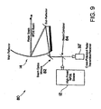
Fig. 9 is a schematic diagram of a multi-functional RFDE system incorporating a reflector-type antenna in accordance with an embodiment of the present invention. - The present invention will now be described with reference to the drawings, in which like reference numerals are provided to refer to like elements throughout.
- The RFDE system of the present invention integrates a targeting system, such as a radar targeting system, into an otherwise conventional RFDE system. There are several ways that the targeting system can be integrated into the RFDE system as explained herein. The particular embodiments described below are meant to be merely exemplary. The present invention contemplates not only the particular embodiments described herein, but any system in which a targeting system is integrated in part or in whole within the RFDE system.
- Referring to
Fig. 2 , anRFDE system 30 is shown in accordance with an embodiment of the present invention. Since many of the elements of theRFDE system 30 inFig. 2 are similar to those in theconventional system 10 discussed above with respect toFig. 1 , only the relevant differences with be discussed herein for sake of brevity. In this particular embodiment, a portion of an otherwise conventional RFDE system (notably thehigh power transmitter 12 and/or the transmit antenna 14) forms part of the targeting system. Specifically, during a targeting mode, the highpower RFDE transmitter 12 is controlled by thecontrol block 22 to transmit standard radar tracking signals thru theantenna 14. The radar tracking signals may be any type of conventional radar signal such a pulse or continuous wave radar. The power level of the tracking signals may be a high powered signal, such as the RFDE signal itself, or a relatively low powered signal as more typical in radar tracking applications. - In the embodiment of
Fig. 2 , aseparate radar receiver 32 and radar receiveantenna 34 are used in conjunction with the integrated RFDE/radar transmitter 12. In one embodiment, the RFDE high power output beam intended to destroy or disturb a target is transmitted using the RFDE/radar transmitter 12 andantenna 14. The radar receiveantenna 34 receives portions of the RFDE output beam reflected by the target back towards thesystem 30. Theradar receiver 32 processes the reflected return signals using conventional techniques in order to identify the location of the target. For example, theradar receiver 32 can be coherently linked to the transmitted RFDE output waveform (represented by line 36) so that Doppler processing can be achieved and the direction and range of the target identified. - The
radar receiver 32 provides the target location information to an integratedtargeting system block 38 which feeds the location information to theantenna pointing system 24. Such operation allows theantenna 14 to be directed in both search and track radar functions. - As will be appreciated, the
RFDE system 30 inFig. 2 , as with the various other embodiments of the invention described herein, can operate in both an RFDE mode and a tracking mode. Both modes may be carried out simultaneously as described above, for example, where the high power electromagnetic energy output waveform of the RFDE system also serves as the radar tracking system transmit signal. Alternatively, theRFDE system 30 may switch between the RFDE mode and the tracking mode using a separate RFDE high power beam and lower power radar transmit signals, respectively. So long as thesystem 30 switches between the two modes rapidly enough so as not to lose track of the target, operation between RFDE mode and tracking mode may be time-division multiplexed. - Typically the radar transmitter is one of the most expensive portions of a radar tracking system. Therefore, by using the
RFDE transmitter 12 andantenna 14 to function as the radar transmitter and antenna for targeting, the cost of the targeting system can be drastically reduced. Also, using the radar return of the RFDE high power beam itself to determine the target location can substantially improve the beam pointing accuracy of theRFDE system 30. By using the RFDE high power beam to determine the location of the target, the power density on target will be maximized when standard radar tracking techniques are employed (e.g., monopulse, continuous scan, etc.). - Those of ordinary skill will appreciate that the
RFDE transmitter 12 can be any transmitter suitable for transmitting an RFDE high power beam. For example, theRFDE transmitter 12 may be a single or multiple tube source, or solid state source. Moreover, it will be appreciated that theantenna 14 can be any type of suitable high power antenna which can be mechanically and/or electronically pointed and scanned via theantenna pointing system 24. The transmitter/antenna can also be comprised of an active electronically steered array (AESA), for example, where an array of high power amplifiers/antennas is utilized. The radar receiveantenna 34 can be any type of suitable antenna for receiving the radar return signals. As with theantenna 14, the radar receiveantenna 34 is mechanically and/or electronically pointed and scanned via theantenna pointing system 24. Theantenna pointing system 24 can be a mechanical gimbal or a beam steering computer controlling phase shifters in an electronically steerable array. -
Fig. 3 illustrates another embodiment representing how a tracking system can be integrated with an RFDE system. The embodiment ofFig. 3 , as with the other embodiments described herein, shares many of the same elements asFig. 2 , and thus again only the relevant differences between the embodiments will be discussed for sake of brevity. - Specifically,
Fig. 3 illustrates anRFDE system 40 in which the power amplifier of the tracking system is integrated within the power amplifier of the RFDE system. More particularly, theRFDE transmitter 12 includes a low powerRFDE signal source 42 operating at a first frequency and input to anadder 44. The output of theadder 44 is input to apower amplifier 46 which amplifies the output before being radiated by the transmitantenna 14. A low powerradar signal source 48 at a second frequency is also input to theadder 44. In addition, the low powerradar signal source 48 is input to theradar receiver 32 to provide for coherent processing. Theadder 44 thus outputs the combined RFDE signal source and radar signal source to thepower amplifier 46. Thepower amplifier 46 can be any suitable type of amplifier including, for example, an injection locked magnetron, a klystron, a solid-state amplifier, etc., or an array of any of these types of amplifiers in an AESA embodiment. - In the embodiment of
Fig. 3 , a separate low power radar signal from thesignal source 48 is used. This signal is combined with the RFDE signal from theRFDE signal source 42 prior to the combined signal being amplified by thepower amplifier 46. The frequencies of the RFDE signal and the radar signal do not have to be at the same frequency. In fact, they can be completely Independent of each other within the bandwidth constraints of thepower amplifier 46 and the RFDE transmitantenna 14. It will be appreciated that significant isolation can be achieved between the RFDE and radar signals by filtering out the RFDE signal at the receiveantenna 34 and/orradar receiver 32. - Again, it will be appreciated that the
RFDE system 40 ofFig. 3 may operate in an RFDE mode and a targeting mode. As in the other embodiments described herein, such modes may be carried out simultaneously or in time-multiplexed fashion. In the case where theRFDE signal source 42 andradar signal source 48 are different, one may consider such operation as frequency-multiplexed as will be appreciated. -
Fig. 4 illustrates yet another embodiment of the present invention. In this embodiment, theRFDE system 50 integrates the radar receive antenna into thesame antenna 14 serving as the RFDE and radar transmit antenna. This is accomplished by means of ahigh power circulator 52 which routes the RFDE/radar transmit signals from the sharedtransmitter 12 through to theantenna 14. Reflected signals received by the antenna are routed by thecirculator 52 to thereceiver 32 for processing. In this example, as in the others discussed herein, the RFDE transmit signal may also be the radar transmit signal. The return signal is received by thesame antenna 14 and coupled through thecirculator 52 to thereceiver 32. The radar system thus can provide target information feedback to theantenna pointing system 24. - The
high power circulator 52 can be problematic in that it can be difficult to design a circulator that can handle the typical total power radiated by an RFDE system. Nevertheless, with improvements in materials and technologies such a circulator may someday be commercially feasible. Furthermore, the embodiment ofFig. 4 certainly is very suitable for an AESA system where the output power is broken-up among an array of transmit elements as discussed in more detail below. - In some integrated RFDE/targeting applications it may be desirable only to share the antenna between the RFDE and targeting systems. The RFDE system and the targeting system otherwise operate independently. An example of such an embodiment is shown in
Fig. 5 . - Specifically, the embodiment of
Fig. 5 illustrates a radar system 32' which functions essentially independently of theRFDE system 60 with the exception of sharing a dualpolarized antenna 14. The RFDE system transmits the RFDE high power beam from thetransmitter 12 via the dualpolarized antenna 14 using one polarization (e.g., vertical, right hand circular, etc.). The radar system 32', with its own transmitter/receiver, transmits the radar transmit signal via theantenna 14 using the orthogonal polarization (e.g., horizontal, left hand circular, etc.). The reflected radar return signal received by theantenna 14 is processed by the radar system 32' to provide target location information, again using conventional techniques. As in the other embodiments, the location information is provided to the integrated targetingsystem 38 which provides the information to theantenna pointing system 24. The embodiment ofFig. 5 can be used to provide tracking information and/or is especially suitable for providing range information for the RFDE system. -
Fig. 6 illustrates an embodiment in which AESAs or phased array antennas may be incorporated within the present invention. The embodiment ofFig. 6 is fundamentally the same as the embodiment ofFig. 3 , with the exception that thepower amplifier 46 is represented by an array of power amplifiers 46' included with the RFDE/radar transmitAESA antenna 14. The radar receiveantenna 34 may similarly comprise an AESA antenna. - As is shown in
Fig. 6 , the combined signal from theadder 44 is input to apower splitter 72 within theAESA antenna 14. Thepower splitter 72 separates the signal and provides the split signal torespective phase shifters 74 and power amplifiers 46' corresponding to respective radiator elements 14' in theantenna 14. Theantenna pointing system 24 may steer theantenna 14 by adjusting the phase of thephase shifters 74, as will be appreciated. - Continuing to refer to
Fig. 6 , it will further be appreciated that theradar source 48 andRFDE source 42 can be at different frequencies and still radiate in the same direction. As long as thephase shifters 74 are selected to provide a true time delay (which is fairly common in the art), theantenna 14 may be steered concurrently for both frequencies. - A multifunctional RFDE system of the present invention can be employed on a variety of platforms. For example,
Fig. 7 illustrates an embodiment in which the system is employed on an aircraft. The combined RFDE/radar transmitter 12 and antenna 14 (not shown), for example, are mounted to radiate out the side of the aircraft. A pod is then mounted beneath the aircraft, containing theradar receiver 32 and receive antenna 34 (also not shown). -
Fig. 8 shows an embodiment in which the RFDE system of the present invention can be employed on a wheeled vehicle. For example, the RFDE and radar systems are mounted in the back of the vehicle and share a common antenna. One possiblesuch system 80 is shown inFig. 9 . A highpower RFDE source 12 radiates into a beam transport system comprised of mirrors (e.g., 82) suitable for the frequency of operation. A cross-polarized radar transmit signal from the radar system 32' is then injected into the RFDE beam path by means of a beam combiner/splitter 84. The RFDE and radar transmit signal are then simultaneously transmitted from thecommon antenna 14, in this embodiment a reflector-type antenna. The radar return signal is received by theantenna 14 and directed back to the cross-polarized radar system 32' via themirrors 82 and beam combiner/splitter 84.
Claims (15)
- A multi-functional radio frequency directed energy (RFDE) system (30, 40, 50, 80), comprising:an RFDE transmitter (12) and at least one RFDE antenna (14, 14') for directing high power electromagnetic energy towards a target sufficient to cause high energy damage or disruption of the target;a targeting system (38) for locating the target, the targeting system including a radar transmitter (48) and at least one radar antenna (14, 34) for transmitting and receiving electromagnetic energy to locate the target; andan antenna pointing system (24) for aiming the at least one RFDE antenna (14, 14') at the target based on the location of the target as ascertained by the targeting system (38),wherein at least a portion of the radar transmitter (48) or the at least one radar antenna (14, 34) is integrated within at least a portion of the RFDE transmitter (12) or the at least one RFDE antenna (14, 14'),wherein the radar transmitter (48) is embodied at least partially within the RFDE transmitter (12), and wherein the radar transmitter (48) and the RFDE transmitter comprise a common RF power amplifier (46)
- The multi-functional RFDE system of claim 1, wherein the at least one radar antenna (14, 34) is embodied at least partially within the at least one RFDE antenna (14, 14').
- The multi-functional RFDE system of claim 1, wherein the electromagnetic energy for locating the target is at a first frequency, and the high power electromagnetic energy is at a second frequency different from the first.
- The multi-functional RFDE system of claim 2, wherein the at least one radar antenna (14, 34) functions to transmit the electromagnetic energy for locating the
- The multi-functional RFDE system of claim 4 wherein the at least one radar antenna (14, 34) includes a first radar antenna (14) that functions to transmit the electromagnetic energy for locating the target and to transmit the high power electromagnetic energy, and a second radar antenna (34) that functions to receive the electromagnetic energy reflected from the target in order to locate the target.
- The multi-functional RFDE system of claim 5, wherein the first radar antenna (14) comprises a multi-element phased array.
- The multi-functional RFDE system of claim 4, wherein the at least one radar antenna (14) that functions to transmit the electromagnetic energy for locating the target also functions to receive the electromagnetic energy reflected from the target in order to locate the target.
- The multi-functional RFDE system of claim 7, wherein the at least one radar antenna (14) comprises a dual-polarized antenna.
- The multi-functional RFDE system of claim 1, wherein the system comprises a beam combiner (84) for combining the high power electromagnetic energy with the electromagnetic energy for locating the target in a path between the RFDE transmitter and the RFDE antenna.
- The multi-functional RFDE system of claim 1, wherein the system is configured for operation in a mobile vehicle.
- The multi-functional RFDE system of claim 10, wherein the mobile vehicle is a wheeled-vehicle.
- The multi-functional RFDE system of claim 10, wherein the mobile vehicle is an aircraft.
- A method of operating a multi-functional radio frequency directed energy (RFDE) system, comprising the steps of:utilizing an RFDE transmitter (12) and at least one RFDE antenna (14,14') to direct high power electromagnetic energy towards a target sufficient to cause high energy damage or disruption of the target;utilizing a targeting system (38) to locate the target, the targeting system including a radar transmitter (48) and at least one radar antenna (14,34) for transmitting and receiving electromagnetic energy to locate the target;aiming the at least one RFDE antenna (14,14') at the target based on the location of the target as ascertained by the targeting system (38); andintegrating at least a portion of the radar transmitter or the at least one radar antenna (14,34) within at least a portion of the RFDE transmitter or the at least one RFDE antenna (14,14'), wherein the radar transmitter (48) is embodied at least partially within the RFDE transmitter (12), wherein the radar transmitter (48) and the RFDE transmitter comprise a common RF power amplifier (46).
- The method of claim 13, wherein the at least one radar antenna (14,34) is embodied at least partially within the at least one RFDE antenna (14,14').
- The method of claim 13, wherein the electromagnetic energy for locating the target is at a first frequency, and the high power electromagnetic energy is at a second frequency different from the first.
Applications Claiming Priority (1)
| Application Number | Priority Date | Filing Date | Title |
|---|---|---|---|
| PCT/US2007/001831 WO2008091250A1 (en) | 2007-01-24 | 2007-01-24 | Multifunctional radio frequency directed energy system |
Publications (2)
| Publication Number | Publication Date |
|---|---|
| EP2106525A1 EP2106525A1 (en) | 2009-10-07 |
| EP2106525B1 true EP2106525B1 (en) | 2012-08-29 |
Family
ID=38462299
Family Applications (1)
| Application Number | Title | Priority Date | Filing Date |
|---|---|---|---|
| EP07716958A Not-in-force EP2106525B1 (en) | 2007-01-24 | 2007-01-24 | Multifunctional radio frequency directed energy system |
Country Status (6)
| Country | Link |
|---|---|
| EP (1) | EP2106525B1 (en) |
| JP (1) | JP2010517035A (en) |
| AU (1) | AU2007344661B2 (en) |
| CA (1) | CA2669898C (en) |
| IL (1) | IL198754A (en) |
| WO (1) | WO2008091250A1 (en) |
Cited By (1)
| Publication number | Priority date | Publication date | Assignee | Title |
|---|---|---|---|---|
| WO2020234564A1 (en) * | 2019-05-23 | 2020-11-26 | Bae Systems Plc | Airborne redirection unit for deflecting a radio frequency energy beam |
Families Citing this family (3)
| Publication number | Priority date | Publication date | Assignee | Title |
|---|---|---|---|---|
| DE102010053896A1 (en) * | 2010-12-09 | 2012-06-14 | Lfk-Lenkflugkörpersysteme Gmbh | Target engagement system |
| JP6127369B2 (en) * | 2012-03-16 | 2017-05-17 | 日本電気株式会社 | Radar apparatus and radar detection method |
| JP2015081787A (en) * | 2013-10-21 | 2015-04-27 | 三菱電機株式会社 | Rcs reducing apparatus, and attachable/detachable outfit |
Family Cites Families (8)
| Publication number | Priority date | Publication date | Assignee | Title |
|---|---|---|---|---|
| JPS58195799A (en) * | 1982-05-12 | 1983-11-15 | 株式会社日立製作所 | How to destroy fast moving objects |
| JPH01121698A (en) * | 1987-11-05 | 1989-05-15 | Mitsubishi Electric Corp | Laser irradiator |
| JPH0273182A (en) * | 1988-09-07 | 1990-03-13 | Mitsubishi Electric Corp | Transmission and reception controller |
| US5936229A (en) * | 1996-04-02 | 1999-08-10 | Trw Inc. | Tracking means for distant ballistic missile targets comprising means for tracking largest radius of curvature |
| US6347001B1 (en) * | 1998-11-03 | 2002-02-12 | Trex Communications Corporation | Free-space laser communication system having six axes of movement |
| US6961171B2 (en) * | 2002-10-17 | 2005-11-01 | Raytheon Company | Phase conjugate relay mirror apparatus for high energy laser system and method |
| US7044044B2 (en) * | 2003-10-17 | 2006-05-16 | Computer Science Corporation | Radio frequency triggered directed energy munition |
| US7515094B2 (en) * | 2004-10-18 | 2009-04-07 | Nokomis, Inc. | Advanced electromagnetic location of electronic equipment |
-
2007
- 2007-01-24 AU AU2007344661A patent/AU2007344661B2/en not_active Ceased
- 2007-01-24 EP EP07716958A patent/EP2106525B1/en not_active Not-in-force
- 2007-01-24 IL IL198754A patent/IL198754A/en not_active IP Right Cessation
- 2007-01-24 JP JP2009547207A patent/JP2010517035A/en active Pending
- 2007-01-24 WO PCT/US2007/001831 patent/WO2008091250A1/en not_active Ceased
- 2007-01-24 CA CA2669898A patent/CA2669898C/en not_active Expired - Fee Related
Cited By (2)
| Publication number | Priority date | Publication date | Assignee | Title |
|---|---|---|---|---|
| WO2020234564A1 (en) * | 2019-05-23 | 2020-11-26 | Bae Systems Plc | Airborne redirection unit for deflecting a radio frequency energy beam |
| US12113280B2 (en) | 2019-05-23 | 2024-10-08 | Bae Systems Plc | Airborne redirection unit for deflecting a radio frequency energy beam |
Also Published As
| Publication number | Publication date |
|---|---|
| EP2106525A1 (en) | 2009-10-07 |
| CA2669898C (en) | 2012-04-03 |
| WO2008091250A1 (en) | 2008-07-31 |
| AU2007344661B2 (en) | 2011-06-09 |
| CA2669898A1 (en) | 2008-07-31 |
| AU2007344661A1 (en) | 2008-07-31 |
| JP2010517035A (en) | 2010-05-20 |
| IL198754A (en) | 2014-04-30 |
| IL198754A0 (en) | 2010-02-17 |
Similar Documents
| Publication | Publication Date | Title |
|---|---|---|
| US7629918B2 (en) | Multifunctional radio frequency directed energy system | |
| US7345625B1 (en) | Radar polarization calibration and correction | |
| EP2726810B1 (en) | Active retrodirective antenna array with a virtual beacon | |
| US20100060517A1 (en) | Partitioned aperture array antenna | |
| EP1003049B1 (en) | Repeater jamming transmitter and casing for the same | |
| EP2165387B1 (en) | High power phased array antenna system | |
| US6646599B1 (en) | Open loop array antenna beam steering architecture | |
| CA2669898C (en) | Multifunctional radio frequency directed energy system | |
| US11349202B2 (en) | Antenna device and radar including the same | |
| US20220263234A1 (en) | Vehicle antenna apparatus, method of use and manufacture | |
| CA2608128A1 (en) | Phased array radar antenna having reduced search time and method for use thereof | |
| Gaitanakis et al. | On the use of AESA (active electronically scanned array) radar and IRST (infrared search&track) system to detect and track low observable threats | |
| KR20050086593A (en) | Optically and frequency scanned array | |
| US6545630B1 (en) | Efficient beam steering for closed loop polarization agile transmitter | |
| EP0390334B1 (en) | Improved data link using electronically steerable beam | |
| EP3281032B1 (en) | An improved antenna system for providing identification functionality | |
| Gaitanakis et al. | AESA radar and IRST against low observable threats | |
| EP0621654A2 (en) | An active antenna array | |
| JP3118247B2 (en) | Space-fed array antenna with dual phase shifters | |
| US6952179B1 (en) | Radar system | |
| Abrams | The microwave power module: A'supercomponent'for radar transmitters | |
| GB2409361A (en) | Radar system | |
| EP2427782B1 (en) | Radar apparatus with amplifier duplexer | |
| Herper et al. | Combined radar and illuminator for sea skimmers (CRISS) | |
| Tahim | Multi-band antenna technology |
Legal Events
| Date | Code | Title | Description |
|---|---|---|---|
| PUAI | Public reference made under article 153(3) epc to a published international application that has entered the european phase |
Free format text: ORIGINAL CODE: 0009012 |
|
| 17P | Request for examination filed |
Effective date: 20090723 |
|
| AK | Designated contracting states |
Kind code of ref document: A1 Designated state(s): AT BE BG CH CY CZ DE DK EE ES FI FR GB GR HU IE IS IT LI LT LU LV MC NL PL PT RO SE SI SK TR |
|
| DAX | Request for extension of the european patent (deleted) | ||
| GRAP | Despatch of communication of intention to grant a patent |
Free format text: ORIGINAL CODE: EPIDOSNIGR1 |
|
| GRAS | Grant fee paid |
Free format text: ORIGINAL CODE: EPIDOSNIGR3 |
|
| GRAA | (expected) grant |
Free format text: ORIGINAL CODE: 0009210 |
|
| AK | Designated contracting states |
Kind code of ref document: B1 Designated state(s): AT BE BG CH CY CZ DE DK EE ES FI FR GB GR HU IE IS IT LI LT LU LV MC NL PL PT RO SE SI SK TR |
|
| REG | Reference to a national code |
Ref country code: GB Ref legal event code: FG4D |
|
| REG | Reference to a national code |
Ref country code: CH Ref legal event code: EP |
|
| REG | Reference to a national code |
Ref country code: AT Ref legal event code: REF Ref document number: 573285 Country of ref document: AT Kind code of ref document: T Effective date: 20120915 |
|
| REG | Reference to a national code |
Ref country code: IE Ref legal event code: FG4D |
|
| REG | Reference to a national code |
Ref country code: DE Ref legal event code: R096 Ref document number: 602007025105 Country of ref document: DE Effective date: 20121025 |
|
| REG | Reference to a national code |
Ref country code: AT Ref legal event code: MK05 Ref document number: 573285 Country of ref document: AT Kind code of ref document: T Effective date: 20120829 |
|
| REG | Reference to a national code |
Ref country code: NL Ref legal event code: VDEP Effective date: 20120829 |
|
| REG | Reference to a national code |
Ref country code: LT Ref legal event code: MG4D Effective date: 20120829 |
|
| PG25 | Lapsed in a contracting state [announced via postgrant information from national office to epo] |
Ref country code: IS Free format text: LAPSE BECAUSE OF FAILURE TO SUBMIT A TRANSLATION OF THE DESCRIPTION OR TO PAY THE FEE WITHIN THE PRESCRIBED TIME-LIMIT Effective date: 20121229 Ref country code: FI Free format text: LAPSE BECAUSE OF FAILURE TO SUBMIT A TRANSLATION OF THE DESCRIPTION OR TO PAY THE FEE WITHIN THE PRESCRIBED TIME-LIMIT Effective date: 20120829 Ref country code: AT Free format text: LAPSE BECAUSE OF FAILURE TO SUBMIT A TRANSLATION OF THE DESCRIPTION OR TO PAY THE FEE WITHIN THE PRESCRIBED TIME-LIMIT Effective date: 20120829 Ref country code: LT Free format text: LAPSE BECAUSE OF FAILURE TO SUBMIT A TRANSLATION OF THE DESCRIPTION OR TO PAY THE FEE WITHIN THE PRESCRIBED TIME-LIMIT Effective date: 20120829 |
|
| PG25 | Lapsed in a contracting state [announced via postgrant information from national office to epo] |
Ref country code: SE Free format text: LAPSE BECAUSE OF FAILURE TO SUBMIT A TRANSLATION OF THE DESCRIPTION OR TO PAY THE FEE WITHIN THE PRESCRIBED TIME-LIMIT Effective date: 20120829 Ref country code: PT Free format text: LAPSE BECAUSE OF FAILURE TO SUBMIT A TRANSLATION OF THE DESCRIPTION OR TO PAY THE FEE WITHIN THE PRESCRIBED TIME-LIMIT Effective date: 20121231 Ref country code: SI Free format text: LAPSE BECAUSE OF FAILURE TO SUBMIT A TRANSLATION OF THE DESCRIPTION OR TO PAY THE FEE WITHIN THE PRESCRIBED TIME-LIMIT Effective date: 20120829 Ref country code: GR Free format text: LAPSE BECAUSE OF FAILURE TO SUBMIT A TRANSLATION OF THE DESCRIPTION OR TO PAY THE FEE WITHIN THE PRESCRIBED TIME-LIMIT Effective date: 20121130 Ref country code: LV Free format text: LAPSE BECAUSE OF FAILURE TO SUBMIT A TRANSLATION OF THE DESCRIPTION OR TO PAY THE FEE WITHIN THE PRESCRIBED TIME-LIMIT Effective date: 20120829 Ref country code: BE Free format text: LAPSE BECAUSE OF FAILURE TO SUBMIT A TRANSLATION OF THE DESCRIPTION OR TO PAY THE FEE WITHIN THE PRESCRIBED TIME-LIMIT Effective date: 20120829 |
|
| PG25 | Lapsed in a contracting state [announced via postgrant information from national office to epo] |
Ref country code: DK Free format text: LAPSE BECAUSE OF FAILURE TO SUBMIT A TRANSLATION OF THE DESCRIPTION OR TO PAY THE FEE WITHIN THE PRESCRIBED TIME-LIMIT Effective date: 20120829 Ref country code: ES Free format text: LAPSE BECAUSE OF FAILURE TO SUBMIT A TRANSLATION OF THE DESCRIPTION OR TO PAY THE FEE WITHIN THE PRESCRIBED TIME-LIMIT Effective date: 20121210 Ref country code: NL Free format text: LAPSE BECAUSE OF FAILURE TO SUBMIT A TRANSLATION OF THE DESCRIPTION OR TO PAY THE FEE WITHIN THE PRESCRIBED TIME-LIMIT Effective date: 20120829 Ref country code: EE Free format text: LAPSE BECAUSE OF FAILURE TO SUBMIT A TRANSLATION OF THE DESCRIPTION OR TO PAY THE FEE WITHIN THE PRESCRIBED TIME-LIMIT Effective date: 20120829 Ref country code: CZ Free format text: LAPSE BECAUSE OF FAILURE TO SUBMIT A TRANSLATION OF THE DESCRIPTION OR TO PAY THE FEE WITHIN THE PRESCRIBED TIME-LIMIT Effective date: 20120829 Ref country code: RO Free format text: LAPSE BECAUSE OF FAILURE TO SUBMIT A TRANSLATION OF THE DESCRIPTION OR TO PAY THE FEE WITHIN THE PRESCRIBED TIME-LIMIT Effective date: 20120829 |
|
| PG25 | Lapsed in a contracting state [announced via postgrant information from national office to epo] |
Ref country code: IT Free format text: LAPSE BECAUSE OF FAILURE TO SUBMIT A TRANSLATION OF THE DESCRIPTION OR TO PAY THE FEE WITHIN THE PRESCRIBED TIME-LIMIT Effective date: 20120829 Ref country code: SK Free format text: LAPSE BECAUSE OF FAILURE TO SUBMIT A TRANSLATION OF THE DESCRIPTION OR TO PAY THE FEE WITHIN THE PRESCRIBED TIME-LIMIT Effective date: 20120829 Ref country code: CY Free format text: LAPSE BECAUSE OF FAILURE TO SUBMIT A TRANSLATION OF THE DESCRIPTION OR TO PAY THE FEE WITHIN THE PRESCRIBED TIME-LIMIT Effective date: 20120829 Ref country code: PL Free format text: LAPSE BECAUSE OF FAILURE TO SUBMIT A TRANSLATION OF THE DESCRIPTION OR TO PAY THE FEE WITHIN THE PRESCRIBED TIME-LIMIT Effective date: 20120829 |
|
| PLBE | No opposition filed within time limit |
Free format text: ORIGINAL CODE: 0009261 |
|
| STAA | Information on the status of an ep patent application or granted ep patent |
Free format text: STATUS: NO OPPOSITION FILED WITHIN TIME LIMIT |
|
| PG25 | Lapsed in a contracting state [announced via postgrant information from national office to epo] |
Ref country code: BG Free format text: LAPSE BECAUSE OF FAILURE TO SUBMIT A TRANSLATION OF THE DESCRIPTION OR TO PAY THE FEE WITHIN THE PRESCRIBED TIME-LIMIT Effective date: 20121129 |
|
| 26N | No opposition filed |
Effective date: 20130530 |
|
| PG25 | Lapsed in a contracting state [announced via postgrant information from national office to epo] |
Ref country code: MC Free format text: LAPSE BECAUSE OF NON-PAYMENT OF DUE FEES Effective date: 20130131 |
|
| REG | Reference to a national code |
Ref country code: CH Ref legal event code: PL |
|
| REG | Reference to a national code |
Ref country code: DE Ref legal event code: R097 Ref document number: 602007025105 Country of ref document: DE Effective date: 20130530 |
|
| REG | Reference to a national code |
Ref country code: IE Ref legal event code: MM4A |
|
| PG25 | Lapsed in a contracting state [announced via postgrant information from national office to epo] |
Ref country code: CH Free format text: LAPSE BECAUSE OF NON-PAYMENT OF DUE FEES Effective date: 20130131 Ref country code: LI Free format text: LAPSE BECAUSE OF NON-PAYMENT OF DUE FEES Effective date: 20130131 |
|
| PG25 | Lapsed in a contracting state [announced via postgrant information from national office to epo] |
Ref country code: IE Free format text: LAPSE BECAUSE OF NON-PAYMENT OF DUE FEES Effective date: 20130124 |
|
| PG25 | Lapsed in a contracting state [announced via postgrant information from national office to epo] |
Ref country code: TR Free format text: LAPSE BECAUSE OF FAILURE TO SUBMIT A TRANSLATION OF THE DESCRIPTION OR TO PAY THE FEE WITHIN THE PRESCRIBED TIME-LIMIT Effective date: 20120829 |
|
| PG25 | Lapsed in a contracting state [announced via postgrant information from national office to epo] |
Ref country code: HU Free format text: LAPSE BECAUSE OF FAILURE TO SUBMIT A TRANSLATION OF THE DESCRIPTION OR TO PAY THE FEE WITHIN THE PRESCRIBED TIME-LIMIT; INVALID AB INITIO Effective date: 20070124 Ref country code: LU Free format text: LAPSE BECAUSE OF NON-PAYMENT OF DUE FEES Effective date: 20130124 |
|
| REG | Reference to a national code |
Ref country code: FR Ref legal event code: PLFP Year of fee payment: 10 |
|
| REG | Reference to a national code |
Ref country code: FR Ref legal event code: PLFP Year of fee payment: 11 |
|
| REG | Reference to a national code |
Ref country code: FR Ref legal event code: PLFP Year of fee payment: 12 |
|
| PGFP | Annual fee paid to national office [announced via postgrant information from national office to epo] |
Ref country code: GB Payment date: 20200115 Year of fee payment: 14 Ref country code: DE Payment date: 20200114 Year of fee payment: 14 |
|
| PGFP | Annual fee paid to national office [announced via postgrant information from national office to epo] |
Ref country code: FR Payment date: 20201210 Year of fee payment: 15 |
|
| REG | Reference to a national code |
Ref country code: DE Ref legal event code: R119 Ref document number: 602007025105 Country of ref document: DE |
|
| GBPC | Gb: european patent ceased through non-payment of renewal fee |
Effective date: 20210124 |
|
| PG25 | Lapsed in a contracting state [announced via postgrant information from national office to epo] |
Ref country code: GB Free format text: LAPSE BECAUSE OF NON-PAYMENT OF DUE FEES Effective date: 20210124 Ref country code: DE Free format text: LAPSE BECAUSE OF NON-PAYMENT OF DUE FEES Effective date: 20210803 |
|
| PG25 | Lapsed in a contracting state [announced via postgrant information from national office to epo] |
Ref country code: FR Free format text: LAPSE BECAUSE OF NON-PAYMENT OF DUE FEES Effective date: 20220131 |