EP2105885B1 - Method for processing mail using sender and recipient networked mail processing systems - Google Patents
Method for processing mail using sender and recipient networked mail processing systems Download PDFInfo
- Publication number
- EP2105885B1 EP2105885B1 EP09152997.4A EP09152997A EP2105885B1 EP 2105885 B1 EP2105885 B1 EP 2105885B1 EP 09152997 A EP09152997 A EP 09152997A EP 2105885 B1 EP2105885 B1 EP 2105885B1
- Authority
- EP
- European Patent Office
- Prior art keywords
- recipient
- sender
- mail piece
- delivery code
- Prior art date
- Legal status (The legal status is an assumption and is not a legal conclusion. Google has not performed a legal analysis and makes no representation as to the accuracy of the status listed.)
- Expired - Fee Related
Links
- 238000012545 processing Methods 0.000 title claims description 33
- 238000000034 method Methods 0.000 title claims description 12
- 238000004891 communication Methods 0.000 description 15
- 230000008569 process Effects 0.000 description 5
- 238000002360 preparation method Methods 0.000 description 4
- 230000008859 change Effects 0.000 description 3
- 238000012790 confirmation Methods 0.000 description 3
- 230000006870 function Effects 0.000 description 3
- 230000002452 interceptive effect Effects 0.000 description 2
- 238000011835 investigation Methods 0.000 description 2
- 230000009471 action Effects 0.000 description 1
- 238000007792 addition Methods 0.000 description 1
- 230000001174 ascending effect Effects 0.000 description 1
- 230000002354 daily effect Effects 0.000 description 1
- 238000012217 deletion Methods 0.000 description 1
- 230000037430 deletion Effects 0.000 description 1
- 238000010586 diagram Methods 0.000 description 1
- 230000003203 everyday effect Effects 0.000 description 1
- 238000012986 modification Methods 0.000 description 1
- 230000004048 modification Effects 0.000 description 1
- 238000012015 optical character recognition Methods 0.000 description 1
- 230000004044 response Effects 0.000 description 1
- 230000000717 retained effect Effects 0.000 description 1
- 238000006467 substitution reaction Methods 0.000 description 1
Images


Classifications
-
- G—PHYSICS
- G07—CHECKING-DEVICES
- G07B—TICKET-ISSUING APPARATUS; FARE-REGISTERING APPARATUS; FRANKING APPARATUS
- G07B17/00—Franking apparatus
- G07B17/00185—Details internally of apparatus in a franking system, e.g. franking machine at customer or apparatus at post office
-
- G06Q50/60—
-
- G—PHYSICS
- G07—CHECKING-DEVICES
- G07B—TICKET-ISSUING APPARATUS; FARE-REGISTERING APPARATUS; FRANKING APPARATUS
- G07B17/00—Franking apparatus
- G07B17/00185—Details internally of apparatus in a franking system, e.g. franking machine at customer or apparatus at post office
- G07B17/00435—Details specific to central, non-customer apparatus, e.g. servers at post office or vendor
- G07B2017/00451—Address hygiene, i.e. checking and correcting addresses to be printed on mail pieces using address databases
Definitions
- the present invention relates generally to mail processing systems, and more particularly to networked mail processing systems.
- WO 01/29780 A1 relates to an address matching system that maintains a central database of valid addresses. Address matching requests are received by the system from a plurality of remote users located at respective machines ("clients"). Those requests are processed at the central system, and the results are returned to the client that made the request. In addition, novel techniques are implemented for improving the likelihood of obtaining one or more matches from a request.
- mail senders often do not have accurate information when trying to determine the appropriate recipient address for a mall piece, resulting in mail pieces that either include an incorrect recipient address or a generic recipient address.
- the mail piece may be undeliverable or require significant work by the recipient's mailroom to determine the appropriate Intended recipient, resulting in increased operating costs for the recipient's mallroom, as well as a delay in the delivery of the mail piece.
- An object of the invention is to provide a system and method for allowing the sender of a mail piece to obtain an accurate recipient address for the mail piece when the mail piece is being prepared.
- the sender When the sender is preparing a mail piece for delivery to a recipient, the sender can participate in an interactive session with the recipient's mail room, utilizing the networked mail processing systems, to obtain a correct recipient address for a mail piece based on a database of recipient addresses maintained by the recipient's mail processing system.
- the recipient address is only a delivery code to maintain the privacy of the name of the actual employee that should receive the mail piece.
- the mail piece is provided with a code that identifies internally to the recipient's mail room the actual recipient address, upon receipt of the mail piece by the recipient's mail room the mail piece can be properly delivered without requiring significant work by the recipient's mailroom to determine the appropriate intended recipient.
- Fig. 1 a mailroom communication network 10 according to an embodiment of the present invention.
- Network 10 includes a plurality of mailers, e.g., mailer 12, mailer 14, mailer 16, mailer 18. While only four mailers are illustrated in Fig. 1 , it should be understood that any number of mailers may be part of the network 10.
- Each mailer 12-18 may be, for example, a business, corporation, or any other type of entity that has multiple employees with different internal addresses within the entity.
- Each mailer 12-18 operates one or more mail processing systems (MPS) 30 (described further below with respect to Fig. 2 ) to process both outgoing and incoming mail.
- MPS mail processing systems
- Each MPS 30 may be used to process both incoming and outgoing mail, or alternatively an MPS 30 may be dedicated to only processing one of outgoing mail or incoming mail.
- the mailers can optionally include one or more personal computers (PC) 21 that are coupled to the MPS 30 via an internal network, such as illustrated for mailer 12 and mailer 16 in Fig. 1 .
- PC personal computers
- Each of the mailers 12-18 is adapted to communicate with a central data center 20. Such communications can be done utilizing any type of communication network 28, such as, for example, the Internet, a telephone network, or the like. Optionally, each of the mailers 12-18 can communicate directly with one or more of the other mailers 12-18 utilizing the network 28.
- Data center 20 preferably includes a control unit 22 and can optionally include one or more databases 24, as will be described below.
- Control unit 22 can be, for example, a processing unit or the like that is adapted to control operation of the data center 20.
- Data center 20 includes a network interface 26 that provides the necessary communication hardware/software required for the data center 20 to communicate via the network 28 with the mail processing systems 30 operated by the mailers 12-18.
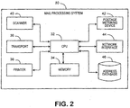
- Fig. 2 illustrates in block diagram form a mail processing system 30 that can be utilized by each of the mailers 12-18 of Fig. 1 .
- Each mail processing system 30 can be, for example, a dedicated mailing machine, a separate computer system, a combination of the two, or any other type of device that can be utilized to process outgoing and/or incoming mail pieces.
- MPS 30 includes a central processing unit 32, which can include, for example, one or more special or general purpose processing devices.
- the CPU 32 controls operation of the MPS 30 using instructions stored in one or more memory units 34.
- the MPS 30 can optionally include a transport 36, such as, for example, rollers and belts, that automate the processing of mail pieces by transporting the mail pieces through the MPS 30.
- a transport 36 such as, for example, rollers and belts, that automate the processing of mail pieces by transporting the mail pieces through the MPS 30.
- transport systems are well known in the art.
- the CPU 32 communicates with a postage metering device 42 that is utilized to generate indicia to evidence payment of postage for mail pieces.
- Postage metering device 42 is preferably a secure coprocessor that performs cryptographic operations and keeps track of funds by maintaining a descending register which stores an amount of funds available for use and an ascending register which stores a total amount of funds dispensed over the life of the metering device 42. Funds may be added to the descending register by any conventional means.
- a printer 38 is used to print information on the mail pieces, such as, for example, indicia generated by the postage metering device 42, address information (either or both of the sender and recipient), ad slogans, and the like.
- Printer 38 may be, for example, an ink jet printer or other conventional type of printing device.
- a scanning or reading device 40 is provided to scan information printed on the mail pieces.
- a network interface 44 provides the necessary communication hardware/software required for the MPS 30 to communicate via the network 28 with the data center 20 and other MPS 30 operated by mailers 12-18, and also to communicate via an internal network with devices internal to the mailer, e.g., PC 21.
- MPS 30 also preferably includes an address database 46 that is utilized to store employee names, titles, roles, code names, identification numbers, etc., along with an internal address for each employee, that enables an employee to be identified internally and located within the mailer's company.
- MPS 30 need not include its own address database 46, and instead each mailer can maintain an address database separate from the MPS 30, such as, for example, database 50 for mailer 14 as illustrated in Fig. 1 , that is accessible by the MPS 30 via an internal network.
- one or more mailers 12-18 can utilize the database 24 located at the data center 20 to store employee information as indicated above.
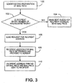
- Fig. 3 illustrates in flow chart form an example of the processing performed during preparation of a mail piece using the mailroom communication network 10 to determine an accurate recipient address for the mail piece.
- the process beings in step 100 where a sender, such as, for example, mailer 12 of Fig. 1 , begins preparation of a mail piece to be delivered to a recipient, e.g., mailer 14 of Fig. 1 .
- a sender such as, for example, mailer 12 of Fig. 1
- the sender has a purpose for the communication and as such has some information with respect to the desired recipient, such as, for example, a name, job title, role, and a delivery address.
- the sender can obtain an accurate recipient address thereby ensuring proper delivery of the mail piece.
- the sender will determine if the intended recipient (mailer 14) is a member of the mailroom network 10. This can be performed, for example, by the MPS 30 of mailer 12 communicating with data center 20 and requesting confirmation if the intended recipient has registered with the data center 20.
- the request can include, for example, the name and mailing address of mailer 14 as known by mailer 12.
- the request for confirmation generated by the MPS 30 can be cryptographically protected, such as for example by encryption or with a digital signature, thereby maintaining privacy of the request and allowing the data center 20 to verify that the request is coming from an authorized MPS 30 that is part of the network 10.
- such a request can be initiated at the PC 21, sent to the MPS 30 using an internal network, and then from the MPS 30 to the data center 20 via network 28.
- the data center 20 can determine if the mailer 14 is a member of the network 10 based on the mailing address of mailer 14. If the intended recipient is not a member of the mailroom network 10, then in step 104 the data center 20 will notify the sender of such and the sender must simply make a best guess as to the recipient address within the recipient entity, address the mail piece using the best guess, and send the mail piece, hoping that it is delivered internally within the recipient entity to the proper recipient address.
- the sender will receive confirmation from the data center 20 that mailer 14 is a member of the mailroom network 10, and the sender (mailer 12) will generate and send a request, using the MPS 30, for a correct recipient address for the mail piece.
- This request includes information associated with the desired recipient based on the purpose of the communication, such as, for example, a specific individual, a job title, a job function within the recipient entity, or any other information that will enable the recipient entity to identify a correct recipient address.
- This request can be sent to the data center 20 via the network 28.
- the data center 20 can respond to the request, using the database 24 maintained by the data center 20.
- the data center 20 can forward the request to the MPS 30 of the intended recipient (mailer 14).
- the response from the data center 20 confirming that the recipient entity is a member of the mailroom network 10 can include a network address for the recipient entity, and the request from MPS 30 of mailer 12 can be sent directly to MPS 30 of mailer 14 via the network 28.
- a correct recipient address for the mail piece is determined, based on the information included in the request, and provided to the sender (either from the data center 20 or the recipient entity). It should be noted that the determination of a correct recipient address may require more than one communication, and can include a series of communications, especially if a match based on the request cannot initially be found. If the determination of the correct recipient address is being performed by the MPS 30 of mailer 14, the determination can be performed by comparing the information in the request to the information stored in the address database 46, or alternatively in the database 50 (if provided). If the determination is being performed by the data center 20, the determination can be performed by comparing the information in the request to the information stored in the database 24.
- the sender may be required to pay a fee for obtaining recipient address information.
- the determination as to whether or not the recipient requires a fee to provide recipient address information can be based on the identity of the sending party.
- Such payment can occur directly between the MPS 30 of mailer 12 and the MPS 30 of mailer 14 (by updating the registers maintained in the postage metering devices 42), or by other conventional means, e.g., using a credit card and data center 20.
- the recipient entity may not wish to provide (or have the datacenter 20 provide) actual employee names and/or locations.
- the recipient address is simply a delivery code that is associated with an actual employee name and location internally to the recipient entity.
- the delivery code is randomly or pseudo-randomly generated such that it is unique for each mail piece.
- the decision of whether or not to provide an actual employee name and location, or simply a delivery code, could be based on the identity of the requesting party.
- a delivery code could be associated with an expiration date, after which mail having the delivery code as the recipient address would not be accepted by the recipient (mailer 14).
- a request may result in a match with more than one name, such as, for example, a request for a recipient address associated with a job function or title.
- the MPS 30 of the intended recipient can determine if more than one recipient address should be provided. This can be based on predetermined rules established by the mailer 14, and programmed into the MPS 30 of mailer 14. Such rules could include, for example, the provision of only a single recipient address for any request, the provision of some maximum number of recipient addresses for any request, etc. The rules could also be based on the identity of the requesting party. It is also possible for the MPS 30 of the recipient (mailer 14) to request additional information from the MPS 30 of the sender (mailer 12) in order to resolve ambiguity when more than one match occurs as a result of the request by mailer 12.
- the correct recipient address can also be provided with one or more conditions that limit the use of the recipient address by the sender. Such conditions could include, for example, a maximum number of uses, a time period for use, etc.
- Use of delivery codes can allow the intended recipient (mailer 14) to determine If the recipient address information is being used within any specified conditions or is being misused by the sender (mailer 12). In the event that the recipient address information is being misused by a particular sender, then the recipient can refuse any subsequent requests for recipient address information from the abusive sender.
- the sender (mailer 12), having received a correct recipient address, evidences or indicates the recipient address on the mail piece, such as, for example, by printing it on the mail piece or on a label that is applied to the mail piece, and sends the mail piece to the recipient (mailer 14).
- the sender can utilize the correct recipient address to change the location of printing and finishing of the mall piece to a location closer to the correct recipient address. This would be particularly valuable in an environment where the price for delivery of mail pieces is based on different zones, or where minimal delivery time is desired.
- the recipient address is some type of delivery code that is internally linked by the recipient to an actual employee name and location. Such a code can be printed as an alphanumeric or numeric code, and may be printed either in a text format, a machine readable format, e.g., a barcode, or a combination thereof.
- Fig. 4 illustrates in flow chart form the processing performed when a mail piece is received by the recipient entity, such as mailer 14 in the above example.
- the mail piece has been received by the mailer 14, in step 120 it is fed into the MPS 30 of mailer 14 and scanned using the scanner 40 to obtain the information on the mail piece.
- This information scanned from the mail piece can be interpreted, using, for example, optical character recognition routines executed by the CPU 32 of the MPS 30, to determine the recipient address information that is printed on the mail piece.
- the recipient address information obtained from the mail piece Is compared with information stored in the address database 46 (or database 50, if provided) by the CPU 32.
- step 124 it is determined, preferably by the CPU 32, if the recipient address from the mail piece is a delivery code. If the recipient address is not a delivery code (and therefore is an actual employee name/location) and the actual employee name/location is correct, then in step 126 the mail piece can be passed through the MPS 30 without any further processing and delivered directly to the actual employee without any further investigation as to the correct intended recipient.
- step 128 it is determined if the delivery code is still a valid delivery code, i.e., is in compliance with any restrictions imposed upon the use of the delivery code as previously described. If use of the delivery code is not in compliance with any imposed restrictions, then in step 130 the mail piece can be marked with some type of indicator, using, for example, the printer 38. The indicator will flag the mail piece for the mailroom personnel of the recipient (mailer 14) as a mail piece that should either be returned to the sender, destroyed, retained for further investigation, or any other action desired by the mailer 14. At this point, however, the mail piece will not be delivered to any recipient, and thus the purpose of the communication can not be fulfilled. It should be understood, of course, that if no conditions of use are provided for the delivery code, then the processing as described In steps 128 and 130 need not occur.
- step 132 the internal delivery instructions for the mail piece, e.g., the name and location of the actual employee to which the mail piece is to be delivered, is determined based on the information stored in the database 46 (or database 50).
- the use of a delivery code can be useful for those individuals that do not work from a fixed location every day, but instead work in different locations on a frequent basis.
- the name and current location to which the mail piece is to be delivered can still easily be determined.
- the delivery code could remain constant despite the fact that the delivery instructions associated with the code could change on a daily basis.
- the MPS 30 of mailer 14 could contact the MPS 30 of mailer 12 to try to resolve the discrepancy and determine a correct recipient address for the mail piece.
- the internal delivery instructions e.g., employee name and location
- the processing performed by the MPS 30 is completed and In step 126, the mail piece can be delivered, using the delivery instructions printed on the mall piece in step 134, by the mailroom personnel.
- the mail processing systems of the sender (mailer 12) and recipient (mailer 14) businesses are networked such that an interactive session can occur to obtain a correct recipient address for a mail piece before the mail piece is sent to the recipient. Since the mail piece is provided with a code that identifies internally to the recipient's mail room the actual recipient address, upon receipt of the mail piece by the recipient's mail room the mail piece can be properly delivered without requiring significant work by the recipient's mailroom to determine the appropriate intended recipient.
Description
- The present invention relates generally to mail processing systems, and more particularly to networked mail processing systems.
-
WO 01/29780 A1 - Numerous postal systems have been developed around the world for the delivery of mail pieces, e.g., letters, flats, packages, and the like. Every postal system operates on the basis of a mailing address, which is a unique formal description of the structure to where a mail piece is to be delivered. The primary purpose of mail pieces is to communicate information fundamentally designed for human consumption. This means that besides a mailing address, there is typically a designated recipient, i.e., the name and internal location of a person within a business where a mail piece Is to be ultimately delivered, also referred to herein as a recipient address. Unfortunately, internal addresses within a business or corporation tend to be quite dynamic, as people often move locations within a company, change job functions, leave the company, or are replaced by new employees. As such, mail senders often do not have accurate information when trying to determine the appropriate recipient address for a mall piece, resulting in mail pieces that either include an incorrect recipient address or a generic recipient address. In either situation, the mail piece may be undeliverable or require significant work by the recipient's mailroom to determine the appropriate Intended recipient, resulting in increased operating costs for the recipient's mallroom, as well as a delay in the delivery of the mail piece.
- It would be desirable, therefore, for a sender of a mall piece to be able to obtain an accurate recipient address for the mail piece when the mail piece is being prepared.
- An object of the invention is to provide a system and method for allowing the sender of a mail piece to obtain an accurate recipient address for the mail piece when the mail piece is being prepared.
- According to the present invention there is provided a method as set out in
Claim 1. - The accompanying drawings illustrate presently preferred embodiments of the invention, and together with the general description given above and the detailed description given below, serve to explain the principles of the invention. As shown throughout the drawings, like reference numerals designate like or corresponding parts. In the drawings:
-
FIG. 1 illustrates a mallroom communication network according to an embodiment of the present invention; -
FIG. 2 illustrates an example of a mail processing system utilized in the mailroom communication network according to an embodiment of the present invention; -
FIG. 3 illustrates in flow chart form an example of the processing performed during preparation of a mail piece using the mailroom communication network; and -
FIG. 4 Illustrates in flow chart form an example of the processing performed when a mail piece is received. - As described in the following mail processing systems of a sender and recipient businesses are networked such that communication can occur between them. When the sender is preparing a mail piece for delivery to a recipient, the sender can participate in an interactive session with the recipient's mail room, utilizing the networked mail processing systems, to obtain a correct recipient address for a mail piece based on a database of recipient addresses maintained by the recipient's mail processing system. The recipient address is only a delivery code to maintain the privacy of the name of the actual employee that should receive the mail piece. Since the mail piece is provided with a code that identifies internally to the recipient's mail room the actual recipient address, upon receipt of the mail piece by the recipient's mail room the mail piece can be properly delivered without requiring significant work by the recipient's mailroom to determine the appropriate intended recipient.
- In describing the present invention, reference is made to the drawings, wherein there is seen in
Fig. 1 amailroom communication network 10 according to an embodiment of the present invention.Network 10 includes a plurality of mailers, e.g.,mailer 12,mailer 14,mailer 16,mailer 18. While only four mailers are illustrated inFig. 1 , it should be understood that any number of mailers may be part of thenetwork 10. Each mailer 12-18 may be, for example, a business, corporation, or any other type of entity that has multiple employees with different internal addresses within the entity. Each mailer 12-18 operates one or more mail processing systems (MPS) 30 (described further below with respect toFig. 2 ) to process both outgoing and incoming mail. EachMPS 30 may be used to process both incoming and outgoing mail, or alternatively anMPS 30 may be dedicated to only processing one of outgoing mail or incoming mail. The mailers can optionally include one or more personal computers (PC) 21 that are coupled to theMPS 30 via an internal network, such as illustrated formailer 12 andmailer 16 inFig. 1 . - Each of the mailers 12-18 is adapted to communicate with a
central data center 20. Such communications can be done utilizing any type ofcommunication network 28, such as, for example, the Internet, a telephone network, or the like. Optionally, each of the mailers 12-18 can communicate directly with one or more of the other mailers 12-18 utilizing thenetwork 28.Data center 20 preferably includes acontrol unit 22 and can optionally include one ormore databases 24, as will be described below.Control unit 22 can be, for example, a processing unit or the like that is adapted to control operation of thedata center 20.Data center 20 includes anetwork interface 26 that provides the necessary communication hardware/software required for thedata center 20 to communicate via thenetwork 28 with themail processing systems 30 operated by the mailers 12-18. -
Fig. 2 illustrates in block diagram form amail processing system 30 that can be utilized by each of the mailers 12-18 ofFig. 1 . Eachmail processing system 30 can be, for example, a dedicated mailing machine, a separate computer system, a combination of the two, or any other type of device that can be utilized to process outgoing and/or incoming mail pieces. There are many different types of mailing machines, ranging from relatively small units that handle only one mail piece at a time, to large, multi-functional units that can process hundreds of mail pieces per hour in a continuous stream operation. MPS 30 includes acentral processing unit 32, which can include, for example, one or more special or general purpose processing devices. TheCPU 32 controls operation of theMPS 30 using instructions stored in one ormore memory units 34. If the MPS 30 is a dedicated mailing machine, it can optionally include atransport 36, such as, for example, rollers and belts, that automate the processing of mail pieces by transporting the mail pieces through the MPS 30. Such transport systems are well known in the art. - The
CPU 32 communicates with apostage metering device 42 that is utilized to generate indicia to evidence payment of postage for mail pieces.Postage metering device 42 is preferably a secure coprocessor that performs cryptographic operations and keeps track of funds by maintaining a descending register which stores an amount of funds available for use and an ascending register which stores a total amount of funds dispensed over the life of themetering device 42. Funds may be added to the descending register by any conventional means. Aprinter 38 is used to print information on the mail pieces, such as, for example, indicia generated by thepostage metering device 42, address information (either or both of the sender and recipient), ad slogans, and the like.Printer 38 may be, for example, an ink jet printer or other conventional type of printing device. A scanning orreading device 40 is provided to scan information printed on the mail pieces. Anetwork interface 44 provides the necessary communication hardware/software required for theMPS 30 to communicate via thenetwork 28 with thedata center 20 and other MPS 30 operated by mailers 12-18, and also to communicate via an internal network with devices internal to the mailer, e.g., PC 21. - MPS 30 also preferably includes an
address database 46 that is utilized to store employee names, titles, roles, code names, identification numbers, etc., along with an internal address for each employee, that enables an employee to be identified internally and located within the mailer's company. Alternatively, MPS 30 need not include itsown address database 46, and instead each mailer can maintain an address database separate from theMPS 30, such as, for example,database 50 formailer 14 as illustrated inFig. 1 , that is accessible by the MPS 30 via an internal network. As yet another alternative, one or more mailers 12-18 can utilize thedatabase 24 located at thedata center 20 to store employee information as indicated above. -
Fig. 3 illustrates in flow chart form an example of the processing performed during preparation of a mail piece using themailroom communication network 10 to determine an accurate recipient address for the mail piece. The process beings instep 100 where a sender, such as, for example,mailer 12 ofFig. 1 , begins preparation of a mail piece to be delivered to a recipient, e.g.,mailer 14 ofFig. 1 . When the sender of a mail piece begins the preparation of the mail piece, the sender has a purpose for the communication and as such has some information with respect to the desired recipient, such as, for example, a name, job title, role, and a delivery address. Using themailroom network 10, the sender can obtain an accurate recipient address thereby ensuring proper delivery of the mail piece. Instep 102, the sender (mailer 12) will determine if the intended recipient (mailer 14) is a member of themailroom network 10. This can be performed, for example, by theMPS 30 ofmailer 12 communicating withdata center 20 and requesting confirmation if the intended recipient has registered with thedata center 20. The request can include, for example, the name and mailing address ofmailer 14 as known bymailer 12. Optionally, the request for confirmation generated by theMPS 30 can be cryptographically protected, such as for example by encryption or with a digital signature, thereby maintaining privacy of the request and allowing thedata center 20 to verify that the request is coming from an authorized MPS 30 that is part of thenetwork 10. Alternatively, such a request can be initiated at the PC 21, sent to the MPS 30 using an internal network, and then from the MPS 30 to thedata center 20 vianetwork 28. Thedata center 20 can determine if themailer 14 is a member of thenetwork 10 based on the mailing address ofmailer 14. If the intended recipient is not a member of themailroom network 10, then instep 104 thedata center 20 will notify the sender of such and the sender must simply make a best guess as to the recipient address within the recipient entity, address the mail piece using the best guess, and send the mail piece, hoping that it is delivered internally within the recipient entity to the proper recipient address. - If the intended recipient is a member of the mailroom network, such as
mailer 14, then instep 106 the sender will receive confirmation from thedata center 20 thatmailer 14 is a member of themailroom network 10, and the sender (mailer 12) will generate and send a request, using theMPS 30, for a correct recipient address for the mail piece. This request includes information associated with the desired recipient based on the purpose of the communication, such as, for example, a specific individual, a job title, a job function within the recipient entity, or any other information that will enable the recipient entity to identify a correct recipient address. This request can be sent to thedata center 20 via thenetwork 28. Thedata center 20 can respond to the request, using thedatabase 24 maintained by thedata center 20. Alternatively, thedata center 20 can forward the request to theMPS 30 of the intended recipient (mailer 14). As yet another alternative, the response from thedata center 20 confirming that the recipient entity is a member of themailroom network 10 can include a network address for the recipient entity, and the request fromMPS 30 ofmailer 12 can be sent directly toMPS 30 ofmailer 14 via thenetwork 28. - In
step 108, a correct recipient address for the mail piece is determined, based on the information included in the request, and provided to the sender (either from thedata center 20 or the recipient entity). It should be noted that the determination of a correct recipient address may require more than one communication, and can include a series of communications, especially if a match based on the request cannot initially be found. If the determination of the correct recipient address is being performed by theMPS 30 ofmailer 14, the determination can be performed by comparing the information in the request to the information stored in theaddress database 46, or alternatively in the database 50 (if provided). If the determination is being performed by thedata center 20, the determination can be performed by comparing the information in the request to the information stored in thedatabase 24. Optionally, the sender may be required to pay a fee for obtaining recipient address information. The determination as to whether or not the recipient requires a fee to provide recipient address information can be based on the identity of the sending party. Such payment can occur directly between theMPS 30 ofmailer 12 and theMPS 30 of mailer 14 (by updating the registers maintained in the postage metering devices 42), or by other conventional means, e.g., using a credit card anddata center 20. - In some Instances, the recipient entity may not wish to provide (or have the
datacenter 20 provide) actual employee names and/or locations. In such a situation, instead of providing a recipient address including the actual name and location of a specific employee, the recipient address is simply a delivery code that is associated with an actual employee name and location internally to the recipient entity. The delivery code is randomly or pseudo-randomly generated such that it is unique for each mail piece. The decision of whether or not to provide an actual employee name and location, or simply a delivery code, could be based on the identity of the requesting party. A delivery code could be associated with an expiration date, after which mail having the delivery code as the recipient address would not be accepted by the recipient (mailer 14). - In some situations, a request may result in a match with more than one name, such as, for example, a request for a recipient address associated with a job function or title. In such situations, the
MPS 30 of the intended recipient can determine if more than one recipient address should be provided. This can be based on predetermined rules established by themailer 14, and programmed into theMPS 30 ofmailer 14. Such rules could include, for example, the provision of only a single recipient address for any request, the provision of some maximum number of recipient addresses for any request, etc. The rules could also be based on the identity of the requesting party. It is also possible for theMPS 30 of the recipient (mailer 14) to request additional information from theMPS 30 of the sender (mailer 12) in order to resolve ambiguity when more than one match occurs as a result of the request bymailer 12. - The correct recipient address (or addresses) can also be provided with one or more conditions that limit the use of the recipient address by the sender.
Such conditions could include, for example, a maximum number of uses, a time period for use, etc. Use of delivery codes can allow the intended recipient (mailer 14) to determine If the recipient address information is being used within any specified conditions or is being misused by the sender (mailer 12). In the event that the recipient address information is being misused by a particular sender, then the recipient can refuse any subsequent requests for recipient address information from the abusive sender. - In
step 110, the sender (mailer 12), having received a correct recipient address, evidences or indicates the recipient address on the mail piece, such as, for example, by printing it on the mail piece or on a label that is applied to the mail piece, and sends the mail piece to the recipient (mailer 14). Optionally, the sender can utilize the correct recipient address to change the location of printing and finishing of the mall piece to a location closer to the correct recipient address. This would be particularly valuable in an environment where the price for delivery of mail pieces is based on different zones, or where minimal delivery time is desired. As noted above, the recipient address is some type of delivery code that is internally linked by the recipient to an actual employee name and location. Such a code can be printed as an alphanumeric or numeric code, and may be printed either in a text format, a machine readable format, e.g., a barcode, or a combination thereof. -
Fig. 4 illustrates in flow chart form the processing performed when a mail piece is received by the recipient entity, such asmailer 14 in the above example. When the mail piece has been received by themailer 14, instep 120 it is fed into theMPS 30 ofmailer 14 and scanned using thescanner 40 to obtain the information on the mail piece. This information scanned from the mail piece can be interpreted, using, for example, optical character recognition routines executed by theCPU 32 of theMPS 30, to determine the recipient address information that is printed on the mail piece. Instep 122, the recipient address information obtained from the mail piece Is compared with information stored in the address database 46 (ordatabase 50, if provided) by theCPU 32. Instep 124, it is determined, preferably by theCPU 32, if the recipient address from the mail piece is a delivery code. If the recipient address is not a delivery code (and therefore is an actual employee name/location) and the actual employee name/location is correct, then instep 126 the mail piece can be passed through theMPS 30 without any further processing and delivered directly to the actual employee without any further investigation as to the correct intended recipient. - If in
step 124 it is determined that the recipient address is a delivery code, then instep 128 it is determined if the delivery code is still a valid delivery code, i.e., is in compliance with any restrictions imposed upon the use of the delivery code as previously described. If use of the delivery code is not in compliance with any imposed restrictions, then Instep 130 the mail piece can be marked with some type of indicator, using, for example, theprinter 38. The indicator will flag the mail piece for the mailroom personnel of the recipient (mailer 14) as a mail piece that should either be returned to the sender, destroyed, retained for further investigation, or any other action desired by themailer 14. At this point, however, the mail piece will not be delivered to any recipient, and thus the purpose of the communication can not be fulfilled. It should be understood, of course, that if no conditions of use are provided for the delivery code, then the processing as described Insteps - If In
step 128 it is determined that the delivery code is still valid, then instep 132 the internal delivery instructions for the mail piece, e.g., the name and location of the actual employee to which the mail piece is to be delivered, is determined based on the information stored in the database 46 (or database 50). The use of a delivery code can be useful for those individuals that do not work from a fixed location every day, but instead work in different locations on a frequent basis. Thus, by providing a delivery code and ensuring that the delivery instructions associated with the delivery code that are stored in thedatabase 46 are current, the name and current location to which the mail piece is to be delivered can still easily be determined. Thus, the delivery code could remain constant despite the fact that the delivery instructions associated with the code could change on a daily basis. Optionally, if there is some discrepancy or issue with determining delivery instructions, e.g., the correct recipient address, theMPS 30 ofmailer 14 could contact theMPS 30 ofmailer 12 to try to resolve the discrepancy and determine a correct recipient address for the mail piece. Once the internal delivery instructions have been determined, then instep 134 the internal delivery instructions, e.g., employee name and location, can be printed on the mail piece using theprinter 38 of theMPS 30. The processing performed by theMPS 30 is completed and Instep 126, the mail piece can be delivered, using the delivery instructions printed on the mall piece instep 134, by the mailroom personnel. - Thus, the mail processing systems of the sender (mailer 12) and recipient (mailer 14) businesses are networked such that an interactive session can occur to obtain a correct recipient address for a mail piece before the mail piece is sent to the recipient. Since the mail piece is provided with a code that identifies internally to the recipient's mail room the actual recipient address, upon receipt of the mail piece by the recipient's mail room the mail piece can be properly delivered without requiring significant work by the recipient's mailroom to determine the appropriate intended recipient.
- While preferred embodiments of the invention have been described and illustrated above, it should be understood that they are exemplary of the invention and are not to be considered as limiting. Additions, deletions, substitutions, and other modifications can be made without departing from the scope of the present invention. Accordingly, the invention is not to be considered as limited by the foregoing description but is only limited by the scope of the appended claims.
Claims (3)
- A method comprising:receiving at a recipient entity mail processing system from a sender mail processing system of a sender of a mall piece a request for an internal recipient address, wherein the internal recipient address comprises a name and internal location of an employee within the recipient entity, and wherein the recipient entity mail processing system and the sender mail processing system are coupled to a network;comparing, in the recipient entity mail processing system, information included in the request with information stored in a database to determine, based on the information included in the request, a correct internal recipient address;providing a delivery code associated with the actual employee name and location internally to the recipient entity from the recipient entity mail processing system to the sender mall processing system, wherein the delivery code is randomly or pseudo-randomly generated such that it is unique for each mail piece;receiving by the recipient entity a mail piece from the sender with the delivery code on it;determining, by the recipient entity mail processing system, based on the delivery code and information stored in the database, the name and location of the actual employee to which the mail piece is to be delivered.
- The method according to claim 1 wherein the delivery code is a barcode.
- The method according to claim 1 or claim 2, further comprising:providing conditions for use of the delivery code comprising an expiration date, maximum number of uses or a time period for use; andafter receiving the mail piece from the sender, determining if the delivery code on the mail piece is still a valid delivery code in compliance with the conditions;and wherein:the step of determining, based on the delivery code and information stored in the database, the name and location of the actual employee to which the mail piece is to be delivered, is performed when it is determined that the delivery code on the mail piece is still a valid delivery code in compliance with the conditions.
Applications Claiming Priority (1)
| Application Number | Priority Date | Filing Date | Title |
|---|---|---|---|
| US12/055,540 US20090248654A1 (en) | 2008-03-26 | 2008-03-26 | System and method for processing mail using sender and recipient networked mail processing systems |
Publications (2)
| Publication Number | Publication Date |
|---|---|
| EP2105885A1 EP2105885A1 (en) | 2009-09-30 |
| EP2105885B1 true EP2105885B1 (en) | 2016-04-13 |
Family
ID=40790575
Family Applications (1)
| Application Number | Title | Priority Date | Filing Date |
|---|---|---|---|
| EP09152997.4A Expired - Fee Related EP2105885B1 (en) | 2008-03-26 | 2009-02-17 | Method for processing mail using sender and recipient networked mail processing systems |
Country Status (2)
| Country | Link |
|---|---|
| US (1) | US20090248654A1 (en) |
| EP (1) | EP2105885B1 (en) |
Families Citing this family (2)
| Publication number | Priority date | Publication date | Assignee | Title |
|---|---|---|---|---|
| JP5216637B2 (en) * | 2009-03-10 | 2013-06-19 | 株式会社富士通ソーシアルサイエンスラボラトリ | E-mail erroneous transmission prevention device, method, and program |
| CA3012670A1 (en) * | 2016-01-29 | 2017-08-03 | Walmart Apollo, Llc | Apparatus and method for maintaining a delivered-package vault |
Citations (1)
| Publication number | Priority date | Publication date | Assignee | Title |
|---|---|---|---|---|
| US20040088252A1 (en) * | 2002-10-30 | 2004-05-06 | Jenny Urs Bernhard | Use of electronic devices for money transfer |
Family Cites Families (25)
| Publication number | Priority date | Publication date | Assignee | Title |
|---|---|---|---|---|
| US5295864A (en) * | 1993-04-06 | 1994-03-22 | The Whitaker Corporation | Sealed coaxial connector |
| US5542089A (en) * | 1994-07-26 | 1996-07-30 | International Business Machines Corporation | Method and apparatus for estimating the number of occurrences of frequent values in a data set |
| US6006211A (en) * | 1997-09-05 | 1999-12-21 | Pitney Bowes Inc. | Metering incoming deliverable mail to identify delivery delays |
| US6064995A (en) * | 1997-09-05 | 2000-05-16 | Pitney Bowes Inc. | Metering incoming mail to detect fraudulent indicia |
| US6032138A (en) * | 1997-09-05 | 2000-02-29 | Pitney Bowes Inc. | Metering incoming deliverable mail |
| DE19812903A1 (en) * | 1998-03-18 | 1999-09-23 | Francotyp Postalia Gmbh | Franking device and a method for generating valid data for franking imprints |
| US6141654A (en) * | 1998-12-30 | 2000-10-31 | Pitney Bowes Inc. | Postage printing system having subsidized printing of third party messages |
| US7505974B2 (en) * | 1999-02-12 | 2009-03-17 | Gropper Robert L | Auto update utility for digital address books |
| US20040083184A1 (en) * | 1999-04-19 | 2004-04-29 | First Data Corporation | Anonymous card transactions |
| FR2793627A1 (en) * | 1999-05-13 | 2000-11-17 | Georges Marc Cornuejols | Message transmission of personal post includes electronic transmission to convenient local printing point, for final delivery by post |
| ATE410754T1 (en) | 1999-10-19 | 2008-10-15 | Stamps Com | SYSTEM AND METHOD FOR ADDRESS COMPARISON |
| US7236970B1 (en) * | 1999-10-19 | 2007-06-26 | Stamps.Com | Address matching system and method |
| US20010027487A1 (en) * | 1999-11-30 | 2001-10-04 | Karl Ruping | Network-based content collection and distribution system |
| US6508365B1 (en) * | 1999-12-28 | 2003-01-21 | Pitney Bowes Inc. | Method of removing mail from a mailstream using an incoming mail sorting apparatus |
| US20010025274A1 (en) * | 2000-06-07 | 2001-09-27 | Wilson Zehr | Method and apparatus for supplementing mailing transaction costs |
| US20020032623A1 (en) * | 2000-03-31 | 2002-03-14 | William Wheeler | Method and apparatus for mail management |
| US6697843B1 (en) * | 2000-04-13 | 2004-02-24 | United Parcel Service Of America, Inc. | Method and system for hybrid mail with distributed processing |
| US20020156645A1 (en) * | 2001-01-31 | 2002-10-24 | Hansen Paul E. | Network-based solution for secure parcel delivery and pick-up |
| US20020138759A1 (en) * | 2001-03-26 | 2002-09-26 | International Business Machines Corporation | System and method for secure delivery of a parcel or document |
| US6740835B2 (en) * | 2001-11-28 | 2004-05-25 | Pitney Bowes Inc. | Method of outsorting return to sender mail using an incoming mail sorting apparatus |
| US6988021B2 (en) * | 2001-12-19 | 2006-01-17 | Pitney Bowes Inc. | Method of addressing and sorting an interoffice distribution using an incoming mail sorting apparatus |
| CA2492492A1 (en) * | 2002-07-18 | 2004-01-29 | Pitney Bowes Inc. | Closed loop postage metering system |
| KR20050021141A (en) * | 2003-08-26 | 2005-03-07 | 주식회사 하나콤 | Method and system for processing returned postal matter using bar-code applied technology |
| WO2005069186A1 (en) * | 2003-12-29 | 2005-07-28 | United States Postal Service | Methods and systems for providing secondary address information |
| US8103518B2 (en) * | 2007-01-12 | 2012-01-24 | United States Postal Service | Systems and methods for new address validation |
-
2008
- 2008-03-26 US US12/055,540 patent/US20090248654A1/en not_active Abandoned
-
2009
- 2009-02-17 EP EP09152997.4A patent/EP2105885B1/en not_active Expired - Fee Related
Patent Citations (1)
| Publication number | Priority date | Publication date | Assignee | Title |
|---|---|---|---|---|
| US20040088252A1 (en) * | 2002-10-30 | 2004-05-06 | Jenny Urs Bernhard | Use of electronic devices for money transfer |
Also Published As
| Publication number | Publication date |
|---|---|
| US20090248654A1 (en) | 2009-10-01 |
| EP2105885A1 (en) | 2009-09-30 |
Similar Documents
| Publication | Publication Date | Title |
|---|---|---|
| US6549892B1 (en) | System for delivering mail | |
| US6385504B1 (en) | Mail processing system with unique mailpiece authorization assigned in advance of mailpieces entering carrier service mail processing stream | |
| US5586036A (en) | Postage payment system with security for sensitive mailer data and enhanced carrier data functionality | |
| RU2309012C2 (en) | Method and device for processing mail items | |
| US8027844B2 (en) | System and method for processing mail | |
| US20040263901A1 (en) | Method and system for tracing corporate mail | |
| JP2001198528A (en) | System and method using digital postal mark as part of added value service of postal system | |
| US7778939B2 (en) | Outbound mail piece tracking | |
| US20100179685A1 (en) | Method, apparatus and logistics system for carrying a mail dispatch | |
| US7021528B2 (en) | System and method for tracking checks | |
| EP1062638A1 (en) | System and method for management of correspondence | |
| US6820065B1 (en) | System and method for management of postage meter licenses | |
| EP2105886A1 (en) | System and method for measuring performance of a mail network | |
| US8126822B1 (en) | Virtual post office box | |
| WO2004050342A2 (en) | Traceable business reply envelopes | |
| AU2003298069B2 (en) | Method and device for processing graphical information located on surfaces of postal articles | |
| EP2105885B1 (en) | Method for processing mail using sender and recipient networked mail processing systems | |
| EP1064621A1 (en) | System and method for management of postage meter licenses | |
| US11544692B1 (en) | Systems and methods using mobile communication handsets for providing postage | |
| EP1669936A2 (en) | Use of machine readable code to print the return address | |
| US7765169B2 (en) | System and method for internal processing of mail using sender and recipient networked mail processing systems | |
| EP1457929A2 (en) | Mail item handling system and method | |
| US20090192850A1 (en) | Method for selecting postal products using formal postal product definitions | |
| CN1708760A (en) | Providing a verifiable delivery payment coding | |
| EP1981001A2 (en) | Method for providing a refund for indicium-based postage |
Legal Events
| Date | Code | Title | Description |
|---|---|---|---|
| PUAI | Public reference made under article 153(3) epc to a published international application that has entered the european phase |
Free format text: ORIGINAL CODE: 0009012 |
|
| AK | Designated contracting states |
Kind code of ref document: A1 Designated state(s): AT BE BG CH CY CZ DE DK EE ES FI FR GB GR HR HU IE IS IT LI LT LU LV MC MK MT NL NO PL PT RO SE SI SK TR |
|
| AX | Request for extension of the european patent |
Extension state: AL BA RS |
|
| 17P | Request for examination filed |
Effective date: 20100219 |
|
| AKX | Designation fees paid |
Designated state(s): DE FR GB |
|
| 17Q | First examination report despatched |
Effective date: 20101115 |
|
| REG | Reference to a national code |
Ref country code: DE Ref legal event code: R079 Ref document number: 602009037662 Country of ref document: DE Free format text: PREVIOUS MAIN CLASS: G07B0017000000 Ipc: G06Q0050320000 |
|
| RIC1 | Information provided on ipc code assigned before grant |
Ipc: G06Q 50/32 20120101AFI20150604BHEP Ipc: G07B 17/00 20060101ALI20150604BHEP |
|
| GRAP | Despatch of communication of intention to grant a patent |
Free format text: ORIGINAL CODE: EPIDOSNIGR1 |
|
| INTG | Intention to grant announced |
Effective date: 20151009 |
|
| RIN1 | Information on inventor provided before grant (corrected) |
Inventor name: CRITELLI, J. MICHAEL Inventor name: CORDERY, ROBERT A. Inventor name: PINTSOV, LEON A. Inventor name: AUSLANDER, JUDITH, D. |
|
| RAP1 | Party data changed (applicant data changed or rights of an application transferred) |
Owner name: PITNEY BOWES INC. |
|
| GRAS | Grant fee paid |
Free format text: ORIGINAL CODE: EPIDOSNIGR3 |
|
| GRAA | (expected) grant |
Free format text: ORIGINAL CODE: 0009210 |
|
| AK | Designated contracting states |
Kind code of ref document: B1 Designated state(s): DE FR GB |
|
| REG | Reference to a national code |
Ref country code: GB Ref legal event code: FG4D |
|
| REG | Reference to a national code |
Ref country code: DE Ref legal event code: R096 Ref document number: 602009037662 Country of ref document: DE |
|
| REG | Reference to a national code |
Ref country code: DE Ref legal event code: R097 Ref document number: 602009037662 Country of ref document: DE |
|
| PLBE | No opposition filed within time limit |
Free format text: ORIGINAL CODE: 0009261 |
|
| STAA | Information on the status of an ep patent application or granted ep patent |
Free format text: STATUS: NO OPPOSITION FILED WITHIN TIME LIMIT |
|
| REG | Reference to a national code |
Ref country code: FR Ref legal event code: PLFP Year of fee payment: 9 |
|
| 26N | No opposition filed |
Effective date: 20170116 |
|
| PGFP | Annual fee paid to national office [announced via postgrant information from national office to epo] |
Ref country code: DE Payment date: 20170227 Year of fee payment: 9 Ref country code: FR Payment date: 20170223 Year of fee payment: 9 |
|
| PGFP | Annual fee paid to national office [announced via postgrant information from national office to epo] |
Ref country code: GB Payment date: 20170227 Year of fee payment: 9 |
|
| REG | Reference to a national code |
Ref country code: DE Ref legal event code: R119 Ref document number: 602009037662 Country of ref document: DE |
|
| GBPC | Gb: european patent ceased through non-payment of renewal fee |
Effective date: 20180217 |
|
| REG | Reference to a national code |
Ref country code: FR Ref legal event code: ST Effective date: 20181031 |
|
| PG25 | Lapsed in a contracting state [announced via postgrant information from national office to epo] |
Ref country code: DE Free format text: LAPSE BECAUSE OF NON-PAYMENT OF DUE FEES Effective date: 20180901 |
|
| PG25 | Lapsed in a contracting state [announced via postgrant information from national office to epo] |
Ref country code: GB Free format text: LAPSE BECAUSE OF NON-PAYMENT OF DUE FEES Effective date: 20180217 Ref country code: FR Free format text: LAPSE BECAUSE OF NON-PAYMENT OF DUE FEES Effective date: 20180228 |