EP2105762A1 - Detection unit for mammography and nuclear medicine diagnosis apparatus for mammography provided therewith - Google Patents
Detection unit for mammography and nuclear medicine diagnosis apparatus for mammography provided therewith Download PDFInfo
- Publication number
- EP2105762A1 EP2105762A1 EP06843513A EP06843513A EP2105762A1 EP 2105762 A1 EP2105762 A1 EP 2105762A1 EP 06843513 A EP06843513 A EP 06843513A EP 06843513 A EP06843513 A EP 06843513A EP 2105762 A1 EP2105762 A1 EP 2105762A1
- Authority
- EP
- European Patent Office
- Prior art keywords
- detector
- gamma
- breast
- mammography
- hollow portion
- Prior art date
- Legal status (The legal status is an assumption and is not a legal conclusion. Google has not performed a legal analysis and makes no representation as to the accuracy of the status listed.)
- Granted
Links
- 238000009607 mammography Methods 0.000 title claims abstract description 63
- 238000009206 nuclear medicine Methods 0.000 title claims description 16
- 238000003745 diagnosis Methods 0.000 title description 6
- 238000001514 detection method Methods 0.000 title description 5
- 210000000481 breast Anatomy 0.000 claims abstract description 159
- 230000005251 gamma ray Effects 0.000 claims abstract description 84
- 210000000323 shoulder joint Anatomy 0.000 claims description 17
- 238000000034 method Methods 0.000 description 8
- 230000000414 obstructive effect Effects 0.000 description 8
- 206010028980 Neoplasm Diseases 0.000 description 5
- 206010006187 Breast cancer Diseases 0.000 description 3
- 208000026310 Breast neoplasm Diseases 0.000 description 3
- 238000010276 construction Methods 0.000 description 3
- 230000004048 modification Effects 0.000 description 3
- 238000012986 modification Methods 0.000 description 3
- 201000011510 cancer Diseases 0.000 description 2
- 238000010586 diagram Methods 0.000 description 2
- 239000003814 drug Substances 0.000 description 2
- 229940079593 drug Drugs 0.000 description 2
- 230000036210 malignancy Effects 0.000 description 2
- 230000002285 radioactive effect Effects 0.000 description 2
- 230000000694 effects Effects 0.000 description 1
- 230000012447 hatching Effects 0.000 description 1
- 239000011159 matrix material Substances 0.000 description 1
- 238000004088 simulation Methods 0.000 description 1
Images




Classifications
-
- G—PHYSICS
- G01—MEASURING; TESTING
- G01T—MEASUREMENT OF NUCLEAR OR X-RADIATION
- G01T1/00—Measuring X-radiation, gamma radiation, corpuscular radiation, or cosmic radiation
- G01T1/29—Measurement performed on radiation beams, e.g. position or section of the beam; Measurement of spatial distribution of radiation
- G01T1/2914—Measurement of spatial distribution of radiation
- G01T1/2985—In depth localisation, e.g. using positron emitters; Tomographic imaging (longitudinal and transverse section imaging; apparatus for radiation diagnosis sequentially in different planes, steroscopic radiation diagnosis)
-
- A—HUMAN NECESSITIES
- A61—MEDICAL OR VETERINARY SCIENCE; HYGIENE
- A61B—DIAGNOSIS; SURGERY; IDENTIFICATION
- A61B6/00—Apparatus or devices for radiation diagnosis; Apparatus or devices for radiation diagnosis combined with radiation therapy equipment
- A61B6/42—Arrangements for detecting radiation specially adapted for radiation diagnosis
- A61B6/4208—Arrangements for detecting radiation specially adapted for radiation diagnosis characterised by using a particular type of detector
- A61B6/4258—Arrangements for detecting radiation specially adapted for radiation diagnosis characterised by using a particular type of detector for detecting non x-ray radiation, e.g. gamma radiation
-
- A—HUMAN NECESSITIES
- A61—MEDICAL OR VETERINARY SCIENCE; HYGIENE
- A61B—DIAGNOSIS; SURGERY; IDENTIFICATION
- A61B6/00—Apparatus or devices for radiation diagnosis; Apparatus or devices for radiation diagnosis combined with radiation therapy equipment
- A61B6/42—Arrangements for detecting radiation specially adapted for radiation diagnosis
- A61B6/4275—Arrangements for detecting radiation specially adapted for radiation diagnosis using a detector unit almost surrounding the patient, e.g. more than 180°
-
- A—HUMAN NECESSITIES
- A61—MEDICAL OR VETERINARY SCIENCE; HYGIENE
- A61B—DIAGNOSIS; SURGERY; IDENTIFICATION
- A61B6/00—Apparatus or devices for radiation diagnosis; Apparatus or devices for radiation diagnosis combined with radiation therapy equipment
- A61B6/50—Apparatus or devices for radiation diagnosis; Apparatus or devices for radiation diagnosis combined with radiation therapy equipment specially adapted for specific body parts; specially adapted for specific clinical applications
- A61B6/502—Apparatus or devices for radiation diagnosis; Apparatus or devices for radiation diagnosis combined with radiation therapy equipment specially adapted for specific body parts; specially adapted for specific clinical applications for diagnosis of breast, i.e. mammography
-
- G—PHYSICS
- G01—MEASURING; TESTING
- G01T—MEASUREMENT OF NUCLEAR OR X-RADIATION
- G01T1/00—Measuring X-radiation, gamma radiation, corpuscular radiation, or cosmic radiation
- G01T1/16—Measuring radiation intensity
- G01T1/161—Applications in the field of nuclear medicine, e.g. in vivo counting
- G01T1/164—Scintigraphy
- G01T1/1641—Static instruments for imaging the distribution of radioactivity in one or two dimensions using one or several scintillating elements; Radio-isotope cameras
- G01T1/1644—Static instruments for imaging the distribution of radioactivity in one or two dimensions using one or several scintillating elements; Radio-isotope cameras using an array of optically separate scintillation elements permitting direct location of scintillations
-
- A—HUMAN NECESSITIES
- A61—MEDICAL OR VETERINARY SCIENCE; HYGIENE
- A61B—DIAGNOSIS; SURGERY; IDENTIFICATION
- A61B6/00—Apparatus or devices for radiation diagnosis; Apparatus or devices for radiation diagnosis combined with radiation therapy equipment
- A61B6/42—Arrangements for detecting radiation specially adapted for radiation diagnosis
- A61B6/4208—Arrangements for detecting radiation specially adapted for radiation diagnosis characterised by using a particular type of detector
- A61B6/4233—Arrangements for detecting radiation specially adapted for radiation diagnosis characterised by using a particular type of detector using matrix detectors
Definitions
- This invention relates to a detector unit for mammography having a gamma-ray detector for detecting gamma rays released from a patient, and a nuclear medicine diagnostic apparatus for mammography having the same.
- an ordinary nuclear medicine diagnostic apparatus includes a gamma-ray detector in a circular or polygonal ring form for detecting gamma rays, and an image processor for producing an RI distribution image based on emission data obtained from the gamma-ray detector.
- the gamma-ray detector includes a scintillator with numerous scintillator chips for emitting light upon incidence of gamma rays, and a photomultiplier tube for converting the light emissions of the scintillator into electric signals.
- a patient is placed in the hollow portion of the gamma-ray detector, and the patient is injected with a radioactive drug labeled with a positron-emitting radioisotope.
- the positron-emitting radioisotope distributed in the body releases two gamma rays in 180-degree opposite directions.
- the gamma-ray detector detects the gamma rays released from the patient.
- the image processor collects, as emission data, events of a pair of gamma rays counted as coincidence, and produces a two-dimensional or three-dimensional RI distribution image based on this emission data.
- the RI distribution image produced is suitable mainly for diagnosing presence or absence, position, malignancy and so on of a tumor.
- the nuclear medicine diagnostic apparatus for mammography there is also a nuclear medicine diagnostic apparatus used mainly for radiographing the breasts (hereinafter called the nuclear medicine diagnostic apparatus for mammography).
- the nuclear medicine diagnostic apparatus for mammography it is effective to find a smaller tumor for the sake of early detection. Therefore, the size of the scintillator chips is reduced, and the gamma-ray detector is constructed to be set close to the patient (see Patent Document 1, for example).
- the conventional nuclear medicine diagnostic apparatus for mammography can place the gamma-ray detector around a breast, but the range of an armpit, a shoulder joint and so on (hereinafter called simply the breast peripheries) cannot be put into the field of view because of the gamma-ray detector hitting against the arm or shoulder.
- breast tissues exist in the breast peripheries as well as the breast, and a breast cancer can develop there. While the breast peripheries also are sites to be examined along with the breast, the conventional example has an inconvenience that the breast tissues of the breast peripheries cannot be diagnosed at the time of diagnosis of the breast.
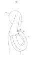
- Fig. 11 is a view showing a positional relationship between the gamma-ray detector and patient M according to the conventional example.
- the gamma-ray detector 61 in the shape of a ring can be placed to surround a breast m1, and the breast m1 comes into its field of view.
- breast peripheries m2 cannot be put into the field of view, as shown, the breast tissues of the breast peripheries cannot be diagnosed.
- This invention has been made having regard to the state of the art noted above, and its object is to provide a detector unit for mammography and a nuclear medicine diagnostic apparatus for mammography having the same, which are capable of putting a breast and peripheries of the breast (armpit, shoulder joint and so on) into a field of view.
- this invention provides the following construction.
- This invention is a detector unit for mammography comprising a gamma-ray detector having a configuration with a cutout formed in part of a closed curve or a polygon having a hollow portion, the hollow portion providing a field of view.
- the detector unit for mammography of this invention in a case that, when placing the gamma-ray detector on a breast, the gamma-ray detector cannot closely contact the breast because sites not to be examined are obstructive, the sites not to be examined may be fitted in the cutout, thereby allowing the gamma-ray detector to contact the breast closely. Since the sites not to be examined are not obstructive, the gamma-ray detector can easily be placed in a position where the breast and breast peripheries enter the field of view at the same time. As a result, breast tissues present in the breast and breast peripheries can be diagnosed efficiently.
- the invention set out in claims 2 is a detector unit for mammography comprising a gamma-ray detector having a configuration with a cutout formed in part of a ring shape having a hollow portion, the hollow portion providing a field of view.
- the detector unit for mammography of this invention in a case that, when placing the gamma-ray detector on a breast, the gamma-ray detector cannot closely contact the breast because sites not to be examined are obstructive, the sites not to be examined may be fitted in the cutout, thereby allowing the gamma-ray detector to contact the breast closely. Since the sites not to be examined are not obstructive, the gamma-ray detector can easily be placed in a position where the breast and breast peripheries enter the field of view at the same time. As a result, breast tissues present in the breast and breast peripheries can be diagnosed efficiently.
- the hollow portion is capable of receiving a breast (claim 3).
- the breast can be placed in the field of view conveniently.
- the gamma-ray detector can be positioned so that, when a top of an arm or a shoulder is inserted in the cutout, at least one of an armpit and a shoulder joint, and the breast, enter the field of view of the gamma-ray detector (claims 4).
- the breast and breast peripheries can be placed in the field of view of the gamma-ray detector at the same time.
- breast tissues present in the breast and breast peripheries can be diagnosed at the same time.
- the invention set out in claim 5 is a detector unit for mammography comprising a gamma-ray detector shaped to surround a lower part of a breast, with one end region thereof placeable up to a shoulder joint above the breast, and the other end region placeable up to an armpit present laterally of the breast, wherein the gamma-ray detector has a field of view corresponding to a hollow portion formed inwardly thereof.
- the detector unit for mammography of this invention when placing the gamma-ray detector on a breast, the gamma-ray detector can closely contact the breast in the absence of obstructions presented by an arm and a shoulder.
- the breast and an armpit or/and a shoulder joint can be placed in the field of view of the gamma-ray detector.
- breast tissues present in the breast and breast peripheries can be diagnosed efficiently.
- the invention set out in claim 6 is a detector unit for mammography comprising a gamma-ray detector shaped to extend downward from an armpit to a lower part of a breast, turn back along the lower part of the breast, and extend to a shoulder joint above the breast, wherein the gamma-ray detector has a field of view corresponding to a hollow portion formed inwardly thereof.
- the detector unit for mammography of this invention when placing the gamma-ray detector on a breast, the gamma-ray detector can closely contact the breast in the absence of obstructions presented by an arm and a shoulder.
- the breast and an armpit or/and a shoulder joint can be placed in the field of view of the gamma-ray detector.
- breast tissues present in the breast and breast peripheries can be diagnosed efficiently.
- the gamma-ray detector is placeable along a body surface of the patient (claim 7).
- the gamma-ray detector can be placed in closer contact with a breast and other sites.
- the gamma-ray detector has a horseshoe shape or a shape of letter U (claim 8).
- the hollow portion is substantially circular (claim 9).
- the substantially circular shape include a perfect circle, a circle close to a perfect circle, and a polygon approximating to a perfect circle, and also include a shape partly deformed with a cutout or the like.
- the hollow portion is 160mm to 250mm in diameter (claim 10). A breast and the like can be diagnosed conveniently.
- the cutout is 50 to 150mm in length (claim 11). A breast and the like can be diagnosed conveniently.
- the hollow portion is approximately teardrop-shaped or approximately elliptical (claim 12).
- the breast peripheries can be put into the field of view more properly.
- the approximately teardrop shape or approximately elliptical shape includes a case of a part being cut off by a cutout or the like.
- the gamma-ray detector has a larger curvature radius in end regions thereof than in regions other than the end regions of the gamma-ray detector (claim 13).
- the breast peripheries can be put into the field of view more properly.
- the hollow portion is columnar (claim 14).
- the gamma-ray detector has detecting planes vertical to a bottom plane of the hollow portion (claim 15).
- the gamma-ray detector has detecting planes inclined relative to a bottom plane of the hollow portion (claims 16).
- the gamma-ray detector is displaced axially of the hollow portion (claim 17). With the gamma-ray detector twisted axially of the hollow portion, the breast peripheries can be put into the field of view properly.
- the gamma-ray detector is divided into two split detectors; wherein the split detectors have one ends thereof separated from each other, and the other ends joined together to render detecting planes of the split detectors continuous; the unit further comprising a split pivotal holding device for pivotably holding at least one of the split detectors, whereby the hollow portion can be enlarged and reduced in size (claim 18).
- the hollow portion can be enlarged or reduced in size according to the size and shape of a breast.
- a plate-like object is provided for closing an outside of a field of view at one side of the hollow portion (claim 19). The breast will never protrude from the field of view.
- an armrest member in form of a flat plate or a curved plate is provided for closing the cutout (claim 20).
- the armrest member provided can prevent an excessive entry of sites not to be examined such an arm and a shoulder, thereby allowing breast tissues to be diagnosed conveniently.
- a restricting member is disposed in the end regions of the gamma-ray detector for contacting at least one of the top of the arm and the shoulder to restrict entry of the arm and the shoulder to the hollow portion (claim 21).
- the restricting member provided can prevent entry of an arm and a shoulder, thereby allowing breast tissues to be diagnosed conveniently.
- the invention set out in claim 22 is a detector unit for mammography comprising a gamma-ray detector having a configuration with a cutout formed in a dome shape or conical shape having a cavity, the cavity providing a field of view.
- the detector unit for mammography of this invention in a case that, when placing the gamma-ray detector on a breast, the gamma-ray detector cannot closely contact the breast because sites not to be examined are obstructive, the sites not to be examined may be fitted in the cutout, thereby allowing the gamma-ray detector to cover the entire breast. Since the sites not to be examined are not obstructive, the gamma-ray detector can easily be placed in a position where the breast and breast peripheries enter the field of view at the same time. As a results, breast tissues present in the entire breast and breast peripheries can be diagnosed efficiently.
- the cavity is capable of receiving a breast (claim 23).
- the breast can be placed in the field of view conveniently.
- At least one of an armpit and a shoulder joint, and the breast can be positioned to enter the field of view of the gamma-ray detector (claim 24).
- the breast and breast peripheries can be placed in the field of view of the gamma-ray detector at the same time.
- breast tissues present in the breast and breast peripheries can be diagnosed at the same time.
- a rotary support device is provided for rotatably supporting the gamma-ray detector (claim 25). Diagnoses of the right and left breasts can be switched easily.
- the rotary support device supports the gamma-ray detector to be rotatable about an axis of the hollow portion (claim 26).
- the invention set out in claim 27 is a nuclear medicine diagnostic apparatus for mammography comprising a detector unit for mammography according to any one of claims 1 to 26; and an image processing device for obtaining an RI distribution image based on emission data collected from the detector unit for mammography.
- an RI distribution image of breast tissues present in a breast and breast peripheries can be produced.
- the breast tissues present in the breast and breast peripheries can be diagnosed efficiently.
- the detector unit for mammography of this invention in a case that, when placing the gamma-ray detector on a breast, the gamma-ray detector cannot closely contact the breast because sites not to be examined are obstructive, the sites not to be examined may be fitted in the cutout, thereby allowing the gamma-ray detector to contact the breast closely. Since the sites not to be examined are not obstructive, the gamma-ray detector can easily be placed in a position where the breast and breast peripheries enter the field of view at the same time. As a result, breast tissues present in the breast and breast peripheries can be diagnosed efficiently.
- a detector unit for mammography comprising a gamma-ray detector having a configuration with a cutout formed in part of a closed curve or a polygon having a hollow portion, the hollow portion providing the field of view.
- FIG. 1 is a block diagram showing an outline of a nuclear medicine diagnostic apparatus for mammography according to the embodiment.
- Fig. 2 (a) is a view in horizontal section of a detector.
- Fig. 2 (b) is a view in vertical section of the detector.
- Fig. 3 is a perspective view of a detector block.
- the nuclear medicine diagnostic apparatus for mammography is an apparatus for diagnosing breast tissues of a patient (human body) M, and includes a detector unit for mammography (hereinafter called simply the detector unit) 1, an image processor 3 and a monitor 5.
- the detector unit 1 includes a detector 11 for detecting gamma rays, a rotary support 17 for rotatably supporting the detector 11, and an armrest member 18 for receiving an arm or the like of the patient M.
- the detector 11 has a configuration having a single cutout B formed in part of a closed curve having a hollow portion A in which a breast can be placed. In other words, the detector 11 is ring-shaped with a part thereof lacking. This detector 11 has detecting planes C formed inside the detector 11, with the hollow portion A providing a field of view.
- the detector 11 corresponds to the gamma-ray detector in this invention.
- the closed curve noted above is circular, and the detector 11 is formed along the curve with part of its circumference cut out.
- the hollow portion A has a diameter whose value is, for example, within a range of 160mm to 250mm.
- the cutout B has an arc length of 50mm to 150mm, for example. However, these dimensions are not limited to these ranges.
- the detector 11 includes numerous detector blocks 21 arranged along the shape of the detector 11, and a housing 23 for accommodating these detector blocks 21.
- each detector block 21 is constructed of a scintillator 31 for converting gamma rays into light, a photomultiplier 33 for converting the light into electric signals, and a light guide 35 for leading the light from the scintillator 31 to the photomultiplier 39.
- the scintillator 31 is an aggregate of scintillator chips 32 arranged in a matrix (e.g. eight rows x eight columns) which is stacked in a plurality of stages (e.g. two stages), and its upper surface acts as a detecting plane of the detector block 21.
- the detecting planes C of the detector 11 noted above are formed of the detecting planes of the detector blocks 21 arranged to face the hollow portion A. Therefore, strictly speaking, the hollow portion A has a shape of a polygon approximating a circle as shown in Fig. 2 .
- the detector blocks 21 are stacked in two stages, the detector 11 becomes a multilayer ring with the scintillator chips 32 arranged in 16 layers.
- the detecting planes C are planes vertical to the bottom of the hollow portion A. Therefore, the hollow portion A has a shape of an approximately cylindrical column (strictly, a polygon).
- the rotary support 17 is connected to the housing 23, whereby the detector 11 is rotatable about one arbitrary axis P.
- the one axis P coincides with the central axis of the approximately circular hollow portion A.
- the armrest member 18 is a plate-like object curved to protrude to the hollow portion A.
- the armrest member 18 has opposite ends thereof connected to opposite end regions of the detector 11 opposed to each other across the cutout B, thereby closing the cutout B.
- the armrest member 18 corresponds to the armrest member in this invention, and corresponds also to the restricting member in this invention.
- the detector unit 1 further includes a plate-like member 9 for closing the outside of the field of view at one side of the hollow portion A.
- the plate-like member 19 corresponds to the plate-like object in this invention.
- the image processor 3 includes a data acquisition unit 41 and an image processing unit 43.
- the data acquisition unit 41 collects emission data from results of detection by the detector unit 1.
- the image processing unit 43 carries out a reconstruction process based on the collected emission data, to produce a two-dimensional or three-dimensional RI distribution image.
- the monitor 5 displays the RI distribution image produced.
- the above image processor 3 is realized by a central processing unit (CPU) for reading and executing a predetermined program, and storage media such as a RAM (Random-Access Memory) and a fixed disk for storing a variety of information.
- CPU central processing unit
- storage media such as a RAM (Random-Access Memory) and a fixed disk for storing a variety of information.
- Fig. 4 is a view schematically showing a positional relationship between the detector 11 and patient M.
- either the right or left breast of the patient M is placed in the hollow portion A, the top of the arm or/and the shoulder on the same side as the breast of the patient M is/are inserted in the cutout B, and the arm, for example, is placed in contact with the armrest member 18.
- the detector 11 surrounds a lower part of the breast, with one end region of the detector 11 located in a range up to the shoulder joint above the breast, and the other end region of the detector 11 located in a range up to the armpit present laterally of the breast. Therefore, the breast peripheries such as the armpit and shoulder joint, and the breast, are placed between the detecting planes C of the detector 11 to enter the field of view of the detector 11. Because of the presence of the armrest member 18, the parts not to be examined such as the arm and shoulder do not enter the field of view of the detector 11 to an excessive extent.
- the patient M is injected with a radioactive drug labelled with a positron-emitting radioisotope.
- the positron-emitting radioisotope releases two gamma rays in 180-degree opposite directions within the patient M.
- the detector 11 detects gamma rays released from the breast and the peripheries of the breast and having reached the detecting planes C, and outputs electric signals.
- the data acquisition unit 41 collects emission data from results of detection by the detector 11. Specifically, each electric signal outputted from the detector 11 is once recorded in the memory successively along with its position information and time information. When the detection by the detector 11 is completed, the data is read from the memory, events of coincidence are determined, and the events are counted to obtain emission data.
- the image processing unit 43 carries out a reconstruction process based on the emission data collected, to produce a two-dimensional or three-dimensional RI distribution image.
- a reconstruction process based on the emission data collected, to produce a two-dimensional or three-dimensional RI distribution image.
- an iterative approximation image reconstruction e.g. OSEM (Ordered Subset Expectation Maximization) algorithm (see Takayuki Nakamura, Hiroyuki Ludo IEEE Nuclear Science Symposium Conference Record 2005 pp. 1950-54 ) is preferred.
- OSEM Organic Subset Expectation Maximization
- a simulation by the reconstruction technique in the OSEM algorithm has been carried out, for example, although not shown here, by uniformly arranging, as inscribed in a circle 208mm in diameter, 12 detector blocks each having scintillator chips 1.5mm square and 4.5mm long stacked longitudinally in four layers and arranged 32 by 32, with one detector block omitted as the cutout B and with none omitted. It has been found, as a result, that this reconstruction technique is almost entirely free from influences of the cutout B, with spatial resolution at 70mm from the center of the field of view being 1.3mm for the case of providing no cutout B, and 1.6mm for the case of providing the cutout B.
- an existing technique may be selected, such as 3D Fourier transform, 3D-FBP, rebinning, 3D reprojection or FORE (Fourier rebinning).
- the RI distribution image produced is outputted to the monitor 5 as appropriate.
- the operator When the diagnosis of one of the right and left breasts is completed, the operator, for example, manually operates the rotary support 17 to rotate the detector 11 about the axis P. This changes the position of the detector 11 to facilitate diagnosis of the other breast. Then, the other breast is diagnosed through the same procedure.
- the nuclear medicine diagnostic apparatus for mammography with the detector 11 which can put a breast and peripheries of the breast into the field of view at the same time, gamma rays released from the breast and breast peripheries can be detected. Therefore, presence or absence, position, malignancy and so on of a tumor can be suitably diagnosed for the breasts and also for breast tissues present around the breasts. As a result, breast cancer can be diagnosed with increased accuracy.
- a breast With the diameter of the hollow portion at 160mm to 200mm, and the arc length of the cutout B at 50mm to 100mm, a breast can be placed in the hollow portion A conveniently, and the top of the arm or the shoulder can be inserted in the cutout B.
- the position of the detector 11 can be changed easily to facilitate diagnosis of each of the right and left breasts.
- the detector unit 1 having the plate-like member 19 for closing the outside of the field of view at one side of the hollow portion, a breast is prevented from protruding from the field of view, and the entire breast can be diagnosed conveniently.
- the detector unit 1 with the armrest member 18 can prevent an excessive entry of an arm, for example. Since the patient M can take a comfortable position, the burden of the patient M can be reduced.
- RI distribution images can be produced appropriately.
Landscapes
- Health & Medical Sciences (AREA)
- Life Sciences & Earth Sciences (AREA)
- Engineering & Computer Science (AREA)
- Medical Informatics (AREA)
- Physics & Mathematics (AREA)
- Molecular Biology (AREA)
- High Energy & Nuclear Physics (AREA)
- Biomedical Technology (AREA)
- General Health & Medical Sciences (AREA)
- Nuclear Medicine, Radiotherapy & Molecular Imaging (AREA)
- Optics & Photonics (AREA)
- Biophysics (AREA)
- Pathology (AREA)
- Heart & Thoracic Surgery (AREA)
- Radiology & Medical Imaging (AREA)
- Surgery (AREA)
- Animal Behavior & Ethology (AREA)
- Public Health (AREA)
- Veterinary Medicine (AREA)
- General Physics & Mathematics (AREA)
- Spectroscopy & Molecular Physics (AREA)
- Oral & Maxillofacial Surgery (AREA)
- Dentistry (AREA)
- Apparatus For Radiation Diagnosis (AREA)
- Nuclear Medicine (AREA)
Abstract
Description
- This invention relates to a detector unit for mammography having a gamma-ray detector for detecting gamma rays released from a patient, and a nuclear medicine diagnostic apparatus for mammography having the same.
- Conventionally, an ordinary nuclear medicine diagnostic apparatus includes a gamma-ray detector in a circular or polygonal ring form for detecting gamma rays, and an image processor for producing an RI distribution image based on emission data obtained from the gamma-ray detector. The gamma-ray detector includes a scintillator with numerous scintillator chips for emitting light upon incidence of gamma rays, and a photomultiplier tube for converting the light emissions of the scintillator into electric signals.
- A patient is placed in the hollow portion of the gamma-ray detector, and the patient is injected with a radioactive drug labeled with a positron-emitting radioisotope. The positron-emitting radioisotope distributed in the body releases two gamma rays in 180-degree opposite directions. The gamma-ray detector detects the gamma rays released from the patient. Then, the image processor collects, as emission data, events of a pair of gamma rays counted as coincidence, and produces a two-dimensional or three-dimensional RI distribution image based on this emission data. The RI distribution image produced is suitable mainly for diagnosing presence or absence, position, malignancy and so on of a tumor.
- Conventionally, there is also a nuclear medicine diagnostic apparatus used mainly for radiographing the breasts (hereinafter called the nuclear medicine diagnostic apparatus for mammography). In the case of breast cancer also, it is effective to find a smaller tumor for the sake of early detection. Therefore, the size of the scintillator chips is reduced, and the gamma-ray detector is constructed to be set close to the patient (see
Patent Document 1, for example). - [Patent Document 1]
Japanese Unexamined Patent Publication No.2003-325499 - However, the conventional example with such construction has the following drawback.
- The conventional nuclear medicine diagnostic apparatus for mammography can place the gamma-ray detector around a breast, but the range of an armpit, a shoulder joint and so on (hereinafter called simply the breast peripheries) cannot be put into the field of view because of the gamma-ray detector hitting against the arm or shoulder. However, breast tissues exist in the breast peripheries as well as the breast, and a breast cancer can develop there. While the breast peripheries also are sites to be examined along with the breast, the conventional example has an inconvenience that the breast tissues of the breast peripheries cannot be diagnosed at the time of diagnosis of the breast.
- This will be described with reference to
Fig. 11. Fig. 11 is a view showing a positional relationship between the gamma-ray detector and patient M according to the conventional example. The gamma-ray detector 61 in the shape of a ring can be placed to surround a breast m1, and the breast m1 comes into its field of view. However, since breast peripheries m2 cannot be put into the field of view, as shown, the breast tissues of the breast peripheries cannot be diagnosed. - This invention has been made having regard to the state of the art noted above, and its object is to provide a detector unit for mammography and a nuclear medicine diagnostic apparatus for mammography having the same, which are capable of putting a breast and peripheries of the breast (armpit, shoulder joint and so on) into a field of view.
- To fulfill the above object, this invention provides the following construction.
- This invention is a detector unit for mammography comprising a gamma-ray detector having a configuration with a cutout formed in part of a closed curve or a polygon having a hollow portion, the hollow portion providing a field of view.
- According to the detector unit for mammography of this invention, in a case that, when placing the gamma-ray detector on a breast, the gamma-ray detector cannot closely contact the breast because sites not to be examined are obstructive, the sites not to be examined may be fitted in the cutout, thereby allowing the gamma-ray detector to contact the breast closely. Since the sites not to be examined are not obstructive, the gamma-ray detector can easily be placed in a position where the breast and breast peripheries enter the field of view at the same time. As a result, breast tissues present in the breast and breast peripheries can be diagnosed efficiently.
- The invention set out in claims 2 is a detector unit for mammography comprising a gamma-ray detector having a configuration with a cutout formed in part of a ring shape having a hollow portion, the hollow portion providing a field of view.
- According to the detector unit for mammography of this invention, in a case that, when placing the gamma-ray detector on a breast, the gamma-ray detector cannot closely contact the breast because sites not to be examined are obstructive, the sites not to be examined may be fitted in the cutout, thereby allowing the gamma-ray detector to contact the breast closely. Since the sites not to be examined are not obstructive, the gamma-ray detector can easily be placed in a position where the breast and breast peripheries enter the field of view at the same time. As a result, breast tissues present in the breast and breast peripheries can be diagnosed efficiently.
- In this invention, it is preferred that the hollow portion is capable of receiving a breast (claim 3). The breast can be placed in the field of view conveniently.
- In this invention, it is preferred that the gamma-ray detector can be positioned so that, when a top of an arm or a shoulder is inserted in the cutout, at least one of an armpit and a shoulder joint, and the breast, enter the field of view of the gamma-ray detector (claims 4). The breast and breast peripheries can be placed in the field of view of the gamma-ray detector at the same time. Thus, breast tissues present in the breast and breast peripheries can be diagnosed at the same time.
- The invention set out in
claim 5 is a detector unit for mammography comprising a gamma-ray detector shaped to surround a lower part of a breast, with one end region thereof placeable up to a shoulder joint above the breast, and the other end region placeable up to an armpit present laterally of the breast, wherein the gamma-ray detector has a field of view corresponding to a hollow portion formed inwardly thereof. - According to the detector unit for mammography of this invention, when placing the gamma-ray detector on a breast, the gamma-ray detector can closely contact the breast in the absence of obstructions presented by an arm and a shoulder. The breast and an armpit or/and a shoulder joint can be placed in the field of view of the gamma-ray detector. Thus, breast tissues present in the breast and breast peripheries can be diagnosed efficiently.
- The invention set out in claim 6 is a detector unit for mammography comprising a gamma-ray detector shaped to extend downward from an armpit to a lower part of a breast, turn back along the lower part of the breast, and extend to a shoulder joint above the breast, wherein the gamma-ray detector has a field of view corresponding to a hollow portion formed inwardly thereof.
- According to the detector unit for mammography of this invention, when placing the gamma-ray detector on a breast, the gamma-ray detector can closely contact the breast in the absence of obstructions presented by an arm and a shoulder. The breast and an armpit or/and a shoulder joint can be placed in the field of view of the gamma-ray detector. Thus, breast tissues present in the breast and breast peripheries can be diagnosed efficiently.
- In this invention, it is preferred that the gamma-ray detector is placeable along a body surface of the patient (claim 7). The gamma-ray detector can be placed in closer contact with a breast and other sites.
- In this invention, it is preferred that the gamma-ray detector has a horseshoe shape or a shape of letter U (claim 8).
- In this invention, it is preferred that the hollow portion is substantially circular (claim 9). The substantially circular shape include a perfect circle, a circle close to a perfect circle, and a polygon approximating to a perfect circle, and also include a shape partly deformed with a cutout or the like.
- In this invention, it is preferred that the hollow portion is 160mm to 250mm in diameter (claim 10). A breast and the like can be diagnosed conveniently.
- In this invention, it is preferred that the cutout is 50 to 150mm in length (claim 11). A breast and the like can be diagnosed conveniently.
- In this invention, it is preferred that the hollow portion is approximately teardrop-shaped or approximately elliptical (claim 12). The breast peripheries can be put into the field of view more properly. The approximately teardrop shape or approximately elliptical shape includes a case of a part being cut off by a cutout or the like.
- In this invention, it is preferred that the gamma-ray detector has a larger curvature radius in end regions thereof than in regions other than the end regions of the gamma-ray detector (claim 13). The breast peripheries can be put into the field of view more properly.
- In this invention, it is preferred that the hollow portion is columnar (claim 14).
- In this invention, it is preferred that the gamma-ray detector has detecting planes vertical to a bottom plane of the hollow portion (claim 15).
- In this invention, it is preferred that the gamma-ray detector has detecting planes inclined relative to a bottom plane of the hollow portion (claims 16).
- In this invention, it is preferred that the gamma-ray detector is displaced axially of the hollow portion (claim 17). With the gamma-ray detector twisted axially of the hollow portion, the breast peripheries can be put into the field of view properly.
- In this invention, it is preferred that the gamma-ray detector is divided into two split detectors; wherein the split detectors have one ends thereof separated from each other, and the other ends joined together to render detecting planes of the split detectors continuous; the unit further comprising a split pivotal holding device for pivotably holding at least one of the split detectors, whereby the hollow portion can be enlarged and reduced in size (claim 18). The hollow portion can be enlarged or reduced in size according to the size and shape of a breast.
- In this invention, it is preferred that a plate-like object is provided for closing an outside of a field of view at one side of the hollow portion (claim 19). The breast will never protrude from the field of view.
- In this invention, it is preferred that an armrest member in form of a flat plate or a curved plate is provided for closing the cutout (claim 20). The armrest member provided can prevent an excessive entry of sites not to be examined such an arm and a shoulder, thereby allowing breast tissues to be diagnosed conveniently.
- In this invention, it is preferred that a restricting member is disposed in the end regions of the gamma-ray detector for contacting at least one of the top of the arm and the shoulder to restrict entry of the arm and the shoulder to the hollow portion (claim 21). The restricting member provided can prevent entry of an arm and a shoulder, thereby allowing breast tissues to be diagnosed conveniently.
- The invention set out in
claim 22 is a detector unit for mammography comprising a gamma-ray detector having a configuration with a cutout formed in a dome shape or conical shape having a cavity, the cavity providing a field of view. - According to the detector unit for mammography of this invention, in a case that, when placing the gamma-ray detector on a breast, the gamma-ray detector cannot closely contact the breast because sites not to be examined are obstructive, the sites not to be examined may be fitted in the cutout, thereby allowing the gamma-ray detector to cover the entire breast. Since the sites not to be examined are not obstructive, the gamma-ray detector can easily be placed in a position where the breast and breast peripheries enter the field of view at the same time. As a results, breast tissues present in the entire breast and breast peripheries can be diagnosed efficiently.
- In this invention, it is preferred that the cavity is capable of receiving a breast (claim 23). The breast can be placed in the field of view conveniently.
- In this invention, it is preferred that, when a top of an arm or a shoulder is inserted in the cutout, at least one of an armpit and a shoulder joint, and the breast, can be positioned to enter the field of view of the gamma-ray detector (claim 24). The breast and breast peripheries can be placed in the field of view of the gamma-ray detector at the same time. Thus, breast tissues present in the breast and breast peripheries can be diagnosed at the same time.
- In this invention, it is preferred that a rotary support device is provided for rotatably supporting the gamma-ray detector (claim 25). Diagnoses of the right and left breasts can be switched easily.
- In this invention, it is preferred that the rotary support device supports the gamma-ray detector to be rotatable about an axis of the hollow portion (claim 26).
- The invention set out in claim 27 is a nuclear medicine diagnostic apparatus for mammography comprising a detector unit for mammography according to any one of
claims 1 to 26; and an image processing device for obtaining an RI distribution image based on emission data collected from the detector unit for mammography. - According to the nuclear medicine diagnostic apparatus for mammography of this invention, an RI distribution image of breast tissues present in a breast and breast peripheries can be produced. Thus, the breast tissues present in the breast and breast peripheries can be diagnosed efficiently.
- According to the detector unit for mammography of this invention, in a case that, when placing the gamma-ray detector on a breast, the gamma-ray detector cannot closely contact the breast because sites not to be examined are obstructive, the sites not to be examined may be fitted in the cutout, thereby allowing the gamma-ray detector to contact the breast closely. Since the sites not to be examined are not obstructive, the gamma-ray detector can easily be placed in a position where the breast and breast peripheries enter the field of view at the same time. As a result, breast tissues present in the breast and breast peripheries can be diagnosed efficiently.
-
-
Fig. 1 is a block diagram showing an outline of a nuclear medicine diagnostic apparatus for mammography according to an embodiment; -
Fig. 2 (a) is a view in horizontal section of a detector; -
Fig. 2 (b) is a view in vertical section taken on line a-a ofFig. 2 (a) ; -
Fig. 3 is a perspective view of a detector block; -
Fig. 4 is a view schematically showing a positional relationship between the detector and a patient; -
Fig. 5 (a) is a view in horizontal section of a detector according to a modified embodiment; -
Fig. 5 (b) is a view in vertical section taken on line b-b ofFig. 5 (a) ; -
Fig. 6 is a view schematically showing a positional relationship between the detector and a patient according to the modified embodiment; -
Fig. 7 is a view in horizontal section of a detector according to a modified embodiment; -
Fig. 8 (a) is a plan view of a detector according to a modified embodiment; -
Fig. 8 (b) is a view in vertical section thereof; -
Fig. 9 is a view in horizontal section of a detector according to a modified embodiment; -
Fig. 10 is a perspective view of a detector according to a modified embodiment; and -
Fig. 11 is a view schematically showing a positional relationship between a detector and a patient according to a conventional example. -
- 1 ... detector unit for mammography
- 3 ... image processor
- 11, 12, 13, 14, 15, 16 ... detectors (gamma-ray detectors)
- 17 ... rotary support
- 18 ... armrest member
- 19 ... plate-like member
- 21 ... detector blocks
- 51 ... split pivotal holder
- A ... hollow portion
- B ... cutout
- C ... detecting planes
- P, Q ... axis
- M ... patient
- The object of putting a breast and peripheries of the breast (armpit, shoulder joint and so on) into a field of view has been fulfilled by a detector unit for mammography comprising a gamma-ray detector having a configuration with a cutout formed in part of a closed curve or a polygon having a hollow portion, the hollow portion providing the field of view.
- An embodiment of this invention will be described hereinafter with reference to the drawing.
Fig. 1 is a block diagram showing an outline of a nuclear medicine diagnostic apparatus for mammography according to the embodiment.Fig. 2 (a) is a view in horizontal section of a detector.Fig. 2 (b) is a view in vertical section of the detector.Fig. 3 is a perspective view of a detector block. - The nuclear medicine diagnostic apparatus for mammography according to this embodiment is an apparatus for diagnosing breast tissues of a patient (human body) M, and includes a detector unit for mammography (hereinafter called simply the detector unit) 1, an
image processor 3 and amonitor 5. - The
detector unit 1 includes adetector 11 for detecting gamma rays, arotary support 17 for rotatably supporting thedetector 11, and anarmrest member 18 for receiving an arm or the like of the patient M. Thedetector 11 has a configuration having a single cutout B formed in part of a closed curve having a hollow portion A in which a breast can be placed. In other words, thedetector 11 is ring-shaped with a part thereof lacking. Thisdetector 11 has detecting planes C formed inside thedetector 11, with the hollow portion A providing a field of view. Thedetector 11 corresponds to the gamma-ray detector in this invention. - A specific configuration of the
detector 11 in this embodiment will be described. The closed curve noted above is circular, and thedetector 11 is formed along the curve with part of its circumference cut out. The hollow portion A has a diameter whose value is, for example, within a range of 160mm to 250mm. The cutout B has an arc length of 50mm to 150mm, for example. However, these dimensions are not limited to these ranges. - More particularly, the
detector 11 includes numerous detector blocks 21 arranged along the shape of thedetector 11, and ahousing 23 for accommodating these detector blocks 21. - As shown in
Fig. 3 , eachdetector block 21 is constructed of ascintillator 31 for converting gamma rays into light, aphotomultiplier 33 for converting the light into electric signals, and alight guide 35 for leading the light from thescintillator 31 to the photomultiplier 39. Thescintillator 31 is an aggregate ofscintillator chips 32 arranged in a matrix (e.g. eight rows x eight columns) which is stacked in a plurality of stages (e.g. two stages), and its upper surface acts as a detecting plane of thedetector block 21. - The detecting planes C of the
detector 11 noted above are formed of the detecting planes of the detector blocks 21 arranged to face the hollow portion A. Therefore, strictly speaking, the hollow portion A has a shape of a polygon approximating a circle as shown inFig. 2 . When the detector blocks 21 are stacked in two stages, thedetector 11 becomes a multilayer ring with the scintillator chips 32 arranged in 16 layers. In this embodiment, as shown inFig. 2 (b) , when seen in a sectional view, the detecting planes C are planes vertical to the bottom of the hollow portion A. Therefore, the hollow portion A has a shape of an approximately cylindrical column (strictly, a polygon). - The
rotary support 17 is connected to thehousing 23, whereby thedetector 11 is rotatable about one arbitrary axis P. In this embodiment, the one axis P coincides with the central axis of the approximately circular hollow portion A. - The
armrest member 18 is a plate-like object curved to protrude to the hollow portion A. Thearmrest member 18 has opposite ends thereof connected to opposite end regions of thedetector 11 opposed to each other across the cutout B, thereby closing the cutout B. Thearmrest member 18 corresponds to the armrest member in this invention, and corresponds also to the restricting member in this invention. - The
detector unit 1 further includes a plate-like member 9 for closing the outside of the field of view at one side of the hollow portion A. The plate-like member 19 corresponds to the plate-like object in this invention. - The
image processor 3 includes adata acquisition unit 41 and animage processing unit 43. Thedata acquisition unit 41 collects emission data from results of detection by thedetector unit 1. Theimage processing unit 43 carries out a reconstruction process based on the collected emission data, to produce a two-dimensional or three-dimensional RI distribution image. Themonitor 5 displays the RI distribution image produced. - The
above image processor 3 is realized by a central processing unit (CPU) for reading and executing a predetermined program, and storage media such as a RAM (Random-Access Memory) and a fixed disk for storing a variety of information. - Next, operation of the nuclear medicine diagnostic apparatus for mammography according to
Embodiment 1 will be described.Fig. 4 is a view schematically showing a positional relationship between thedetector 11 and patient M. - As shown in
Fig. 4 , either the right or left breast of the patient M is placed in the hollow portion A, the top of the arm or/and the shoulder on the same side as the breast of the patient M is/are inserted in the cutout B, and the arm, for example, is placed in contact with thearmrest member 18. As a result, thedetector 11 surrounds a lower part of the breast, with one end region of thedetector 11 located in a range up to the shoulder joint above the breast, and the other end region of thedetector 11 located in a range up to the armpit present laterally of the breast. Therefore, the breast peripheries such as the armpit and shoulder joint, and the breast, are placed between the detecting planes C of thedetector 11 to enter the field of view of thedetector 11. Because of the presence of thearmrest member 18, the parts not to be examined such as the arm and shoulder do not enter the field of view of thedetector 11 to an excessive extent. - Next, the patient M is injected with a radioactive drug labelled with a positron-emitting radioisotope. The positron-emitting radioisotope releases two gamma rays in 180-degree opposite directions within the patient M. The
detector 11 detects gamma rays released from the breast and the peripheries of the breast and having reached the detecting planes C, and outputs electric signals. - The
data acquisition unit 41 collects emission data from results of detection by thedetector 11. Specifically, each electric signal outputted from thedetector 11 is once recorded in the memory successively along with its position information and time information. When the detection by thedetector 11 is completed, the data is read from the memory, events of coincidence are determined, and the events are counted to obtain emission data. - The
image processing unit 43 carries out a reconstruction process based on the emission data collected, to produce a two-dimensional or three-dimensional RI distribution image. As an example of the reconstruction process, an iterative approximation image reconstruction (e.g. OSEM (Ordered Subset Expectation Maximization) algorithm (see Takayuki Nakamura, Hiroyuki Ludo IEEE Nuclear Science Symposium Conference Record 2005 pp. 1950-54) is preferred. According to this technique, an RI distribution image with influences of the cutout B sufficiently inhibited can be produced. - A simulation by the reconstruction technique in the OSEM algorithm has been carried out, for example, although not shown here, by uniformly arranging, as inscribed in a circle 208mm in diameter, 12 detector blocks each having scintillator chips 1.5mm square and 4.5mm long stacked longitudinally in four layers and arranged 32 by 32, with one detector block omitted as the cutout B and with none omitted. It has been found, as a result, that this reconstruction technique is almost entirely free from influences of the cutout B, with spatial resolution at 70mm from the center of the field of view being 1.3mm for the case of providing no cutout B, and 1.6mm for the case of providing the cutout B.
- Instead of the iterative approximation image reconstruction referred to, an existing technique may be selected, such as 3D Fourier transform, 3D-FBP, rebinning, 3D reprojection or FORE (Fourier rebinning).
- The RI distribution image produced is outputted to the
monitor 5 as appropriate. - When the diagnosis of one of the right and left breasts is completed, the operator, for example, manually operates the
rotary support 17 to rotate thedetector 11 about the axis P. This changes the position of thedetector 11 to facilitate diagnosis of the other breast. Then, the other breast is diagnosed through the same procedure. - Thus, according to the nuclear medicine diagnostic apparatus for mammography according to
Embodiment 1, with thedetector 11 which can put a breast and peripheries of the breast into the field of view at the same time, gamma rays released from the breast and breast peripheries can be detected. Therefore, presence or absence, position, malignancy and so on of a tumor can be suitably diagnosed for the breasts and also for breast tissues present around the breasts. As a result, breast cancer can be diagnosed with increased accuracy. - With the diameter of the hollow portion at 160mm to 200mm, and the arc length of the cutout B at 50mm to 100mm, a breast can be placed in the hollow portion A conveniently, and the top of the arm or the shoulder can be inserted in the cutout B.
- With the
detector unit 1 having therotary support 17, the position of thedetector 11 can be changed easily to facilitate diagnosis of each of the right and left breasts. - With the
detector unit 1 having the plate-like member 19 for closing the outside of the field of view at one side of the hollow portion, a breast is prevented from protruding from the field of view, and the entire breast can be diagnosed conveniently. - The
detector unit 1 with thearmrest member 18 can prevent an excessive entry of an arm, for example. Since the patient M can take a comfortable position, the burden of the patient M can be reduced. - With the
image processor 3, RI distribution images can be produced appropriately. - This invention is not limited to the foregoing embodiment, but may be modified as follows:
- (1) In the foregoing embodiment, the closed curve is a circle on the same plane, and the
detector 1 is formed along the curve with part of its circumference cut out. This is not limitative. As long as it is a closed curve or a polygon having a cutout in part thereof, various shapes can be selected as appropriate. Therefore, it is not limited to being on the same plane, either.
Reference is made toFigs. 5 and6 .Fig. 5 (a) is a view in horizontal section of a detector according to a modified embodiment.Fig. 5 (b) is a view in vertical section thereof.Fig. 6 is a view schematically showing a positional relationship between adetector 12 and a patient M according to this modified embodiment. As shown inFigs. 5 and6 , the closed curve is teardrop-shaped, and thedetector 12 has a shape extending along the curve with part of the teardrop-shaped outline cut out. A cutout B is formed adjacent an upper end where the teardrop-shaped outline tapers. The field of view of thedetector 12 corresponds to areas of hollow portions A1 and A2. Incidentally, where thedetector 11 described inEmbodiment 1 is comparable with the width of thedetector 12, the field of view of thedetector 11 can be only a field of view approximately corresponding to the hollow portion A1. Thus, with thedetector 12 according to the modified embodiment, the hollow portion A2 in addition to the hollow portion A1 can provide the field of view. A larger range of breast peripheries can be put into the field of view (inFig. 6 , a breast and breast peripheries included in the field of view of thedetector 12 are specified by hatching).
Besides the shape of thedetector 12 shown in the modified embodiment shown inFigs. 5 and6 , a detector may be provided to have a horseshoe shape, a shape of letter U or a shape of letter C. Instead of the teardrop shape described referring toFig. 5 , a detector may be selected to have an elliptical shape, rugby ball shape or various other outline shapes with a cutout. - (2) Although, in the foregoing embodiment, the position of the cutout B has not particularly been described, but this is a matter selectable as appropriate. For example, a position in the longer direction, shorter direction or other position of the outline of the closed curve, may be selected as appropriate.
Fig. 7 refers.Fig. 7 is a view in horizontal section of a detector according to a modified embodiment. Adetector 13 shown has a shape of an elliptical outline with part thereof cut out. Here, a cutout B is formed in a portion where the minor axis of the ellipse intersects the elliptical outline. - (3) The shape of the
detector 11 may be varied such that the curvature radius in the opposite end regions of thedetector 11 opposed to each other across the cutout B is larger than in regions other than the opposite end regions of thedetector 11. Or, where the opposite end regions of thedetector 11 are not curved, a modification may be made such that the detecting planes C in the opposite end regions opposed to each other across the cutout B are parallel to each other or in a near parallel relationship. Then, the breast peripheries can be put properly and extensively into the field of view. Specifically, the modified embodiment described inFigs. 5 and6 can be given as an example. That is, thedetector 12 shown inFig. 5 has a curvature radius in the opposite end regions of thedetector 12 opposed to each other across the cutout B which is larger than in regions other than the opposite end regions of thedetector 12. - (4) In the embodiment described hereinbefore, the hollow portion A is columnar, but this is not limitative. For example, a modification may be made to incline the detecting planes C of the
detector 11 relative to the bottom of the hollow portion A. Specifically, as in thedetector 12 shown inFig. 5 (b) , the detecting planes may be inclined relative to the bottom of the hollow portions A1 and A2. This allows the detecting planes to be placed close to the breast and breast peripheries. - (5) In the embodiment described hereinbefore, the
detector 11 has a shape of a closed curve with a part thereof cut out, but this is not limitative. For example, the detector may have a shape forming a cutout in the shape of a dome having a cavity which can receive a breast therein. The dome shape may be semispherical, for example. The dome shape may be changed to a conical shape such as of a circular cone or pyramid.
Fig. 8 (a) is a plan view of a detector according to a modified embodiment.Fig. 8 (b) is a view in vertical section thereof. In this modified embodiment, adetector 14 is constructed with a hollow portion A in a shape of a cone (approximately circular cone-shaped). Specifically, detecting planes C of thedetector 14 are inclined relative to the bottom of the hollow portion A, with an upper part of the hollow portion A closed. With thedetector 14 constructed in this way, an entire breast can be accommodated in the hollow portion A, and therefore the entire breast can easily be put into the field of view. The plate-like member 19 described inEmbodiment 1 is dispensable. - (6) In the embodiment described hereinbefore, the hollow portion A formed in the
detector 11 is fixed. A detector may be constructed to have a hollow portion A variable in size.
Fig. 9 refers.Fig. 9 is a view in horizontal section of adetector 15 according to a modified embodiment. Thedetector 15 is dividable into twosplit detectors split detectors housing
Thesplit detectors split detectors split detector 15b is pivotably supported by a splitpivotal holder 51. The splitpivotal holder 51 is disposed in a position adjacent the other ends of thesplit detectors split detector 15b to be pivotable while maintaining the continuity of the detecting planes of thesplit detectors pivotal holder 51, even if the detecting planes of thesplit detectors split detectors
And with a pivotal movement of thesplit detector 15b caused by a manual operation of the operator, the hollow portion A can be enlarged or reduced in size according to the size, shape and so on of a breast.
In the above modified embodiment, thesplit detector 15a is fixedly installed. However, thesplit detector 15a may also be pivotably held by the splitpivotal holder 51. - (7) In the embodiment described hereinbefore, the
rotary support 17 supports thedetector 11 to be rotatable about one axis P coinciding with the central axis of the hollow portion A. This is not limitative. As one axis P, an axis parallel to the central axis of the hollow portion A can be selected separately. As one axis P, even an axis not parallel to the central axis of the hollow portion A can be selected as appropriate. - (8) In the embodiment described hereinbefore, the breast peripheries to be included in the field of view of the
detector 11 are exemplified by the armpit or/and shoulder joint, but these are not limitative. That is, any sites around a breast where breast tissues are present may be selected or varied as appropriate. - (9) The
rotary support 17 and the splitpivotal holder 51 described hereinbefore are both manually operable. Instead, a drive device may be provided separately. - (10) In the embodiment described hereinbefore, the
armrest member 18 is in the form of a curved plate. Without being limited to this, a change may be made to an appropriate shape such as a shape of a flat plate. Thearmrest member 18 closes the cutout B, but instead can be modified not to close it. That is, the mounting position and shape of thearmrest member 18 can be changed as appropriate as long as it can prevent an excessive entry of an arm and a shoulder. As a result, a gap may be formed. Thearmrest member 18 is for receiving an arm and a shoulder, and is not limited to receiving of only an arm. - (11) In the embodiment described hereinbefore, the
detector 11 has the detector blocks 21 stacked in two stages, but this is not limitative. For example, the detector blocks 21 may be in one stage, or three or more stages. Thedetector 11 is a multilayer ring withscintillator chips 32 arranged in multiple layers. Without being limited to this, a change may be made to have the scintillator chips 32 arranged in one layer only. - (12) In the embodiment described hereinbefore, the
detector 11 is not twisted in the direction of the central axis P of the hollow portion A (that is, thedetector 11 from one end to the other end thereof is not displaced relative to the central axis P). This is not limitative.Fig. 10 refers.Fig. 10 is a perspective view of a detector according to a modified embodiment. As shown, adetector 16 may be displaced relative to an axis Q of the hollow portion A. In other words, a change may be made to thedetector 16 having a shape twisted in the direction of axis Q of the hollow portion A. - (13) Although the embodiment described hereinbefore provides the
detector 11 having the circular hollow portion A, this is not limitative. The shape of the detector may be designed as appropriate based on the body surface or shape of an actual or statistically given patient (human body) M. Specifically, a change may be made to a detector having a shape extending downward from an armpit to a lower part of a breast, turning back along the lower part of the breast, and extending to a shoulder joint above the breast. At this time, it is preferred that the detector is shaped to be placeable along the body surface. - (14) A detector unit for mammography or a nuclear medicine diagnostic apparatus for mammography may be constructed by combining the constructions described in the foregoing embodiment and modifications.
Claims (27)
- A detector unit for mammography comprising a gamma-ray detector having a configuration with a cutout formed in part of a closed curve or a polygon having a hollow portion, the hollow portion providing a field of view.
- A detector unit for mammography comprising a gamma-ray detector having a configuration with a cutout formed in part of a ring shape having a hollow portion, the hollow portion providing a field of view.
- The detector unit for mammography according to claims 1 or 2, wherein the hollow portion is capable of receiving a breast.
- The detector unit for mammography according to any one of claims 1 to 3, wherein the gamma-ray detector can be positioned so that, when a top of an arm or a shoulder is inserted in the cutout, at least one of an armpit and a shoulder joint, and the breast, enter the field of view of the gamma-ray detector.
- A detector unit for mammography comprising a gamma-ray detector shaped to surround a lower part of a breast, with one end region thereof placeable up to a shoulder joint above the breast, and the other end region peaceable up to an armpit present laterally of the breast,
wherein the gamma-ray detector has a field of view corresponding to a hollow portion formed inwardly thereof. - A detector unit for mammography comprising a gamma-ray detector shaped to extend downward from an armpit to a lower part of a breast, turn back along the lower part of the breast, and extend to a shoulder joint above the breast,
wherein the gamma-ray detector has a field of view corresponding to a hollow portion formed inwardly thereof. - The detector unit for mammography according to claims 5 or 6, wherein the gamma-ray detector is placeable along a body surface of the patient.
- The detector unit for mammography according to any one of claims 1 to 7, wherein the gamma-ray detector has a horseshoe shape or a shape of letter U.
- The detector unit for mammography according to any one of claims 1 to 7, wherein the hollow portion is substantially circular.
- The detector unit for mammography according to claim 9, wherein the hollow portion is 160mm to 250mm in diameter.
- The detector unit for mammography according to any one of claims 1 to 4, wherein the cutout is 50 to 150mm in length.
- The detector unit for mammography according to any one of claims 1 to 7, wherein the hollow portion is approximately teardrop-shaped or approximately elliptical.
- The detector unit for mammography according to any one of claims 1 to 12, wherein the gamma-ray detector has a larger curvature radius in end regions thereof than in regions other than the end regions of the gamma-ray detector.
- The detector unit for mammography according to any one of claims 1 to 13, wherein the hollow portion is columnar.
- The detector unit for mammography according to any one of claims 1 to 13, wherein the gamma-ray detector has detecting planes vertical to a bottom plane of the hollow portion.
- The detector unit for mammography according to any one of claims 1 to 13, wherein the gamma-ray detector has detecting planes inclined relative to a bottom plane of the hollow portion.
- The detector unit for mammography according to any one of claims 1 to 16, wherein the gamma-ray detector is displaced axially of the hollow portion.
- The detector unit for mammography according to any one of claims 1 to 17, wherein:the gamma-ray detector is divided into two split detectors;wherein the split detectors have one ends thereof separated from each other, and the other ends joined together to render detecting planes of the split detectors continuous;the unit further comprising a split pivotal holding device for pivotably holding at least one of the splint detectors, whereby the hollow portion can be enlarged and reduced in size.
- The detector unit for mammography according to any one of claims 1 to 18, comprising a plate-like object for closing an outside of a field of view at one side of the hollow portion.
- The detector unit for mammography according to any one of claims 1 to 4, comprising an armrest member in form of a flat plate or a curved plate for closing the cutout.
- The detector unit for mammography according to any one of claims 1 to 19, comprising a restricting member disposed in the end regions of the gamma-ray detector for contacting at least one of the top of the arm and the shoulder to restrict entry of the arm and the shoulder to the hollow portion.
- A detector unit for mammography comprising a gamma-ray detector having a configuration with a cutout formed in a dome shape or conical shape having a cavity, the cavity providing a field of view.
- The detector unit for mammography according to claim 22, wherein the cavity is capable of receiving a breast.
- The detector unit for mammography according to claim 22 or 23, wherein, when a top of an arm or a shoulder is inserted in the cutout, at least one of an armpit and a shoulder joint, and the breast, can be positioned to enter the field of view of the gamma-ray detector.
- The detector unit for mammography according to any one of claims 1 to 24, comprising a rotary support device for rotatably supporting the gamma-ray detector.
- The detector unit for mammography according to claim 25, wherein the rotary support device supports the gamma-ray detector to be rotatable about an axis of the hollow portion.
- A nuclear medicine diagnostic apparatus for mammography comprising:a detector unit for mammography according to any one of claims 1 to 26; andan image processing device for obtaining an RI distribution image based on emission data collected from the detector unit for mammography.
Applications Claiming Priority (1)
| Application Number | Priority Date | Filing Date | Title |
|---|---|---|---|
| PCT/JP2006/326131 WO2008081525A1 (en) | 2006-12-27 | 2006-12-27 | Detection unit for mammography and nuclear medicine diagnosis apparatus for mammography provided therewith |
Publications (3)
| Publication Number | Publication Date |
|---|---|
| EP2105762A1 true EP2105762A1 (en) | 2009-09-30 |
| EP2105762A4 EP2105762A4 (en) | 2013-08-21 |
| EP2105762B1 EP2105762B1 (en) | 2016-07-13 |
Family
ID=39588216
Family Applications (1)
| Application Number | Title | Priority Date | Filing Date |
|---|---|---|---|
| EP06843513.0A Not-in-force EP2105762B1 (en) | 2006-12-27 | 2006-12-27 | Detection unit for mammography and nuclear medicine diagnosis apparatus for mammography provided therewith |
Country Status (5)
| Country | Link |
|---|---|
| US (1) | US7961840B2 (en) |
| EP (1) | EP2105762B1 (en) |
| JP (1) | JP4905462B2 (en) |
| CN (1) | CN101568854B (en) |
| WO (1) | WO2008081525A1 (en) |
Cited By (2)
| Publication number | Priority date | Publication date | Assignee | Title |
|---|---|---|---|---|
| CN102327125A (en) * | 2010-06-04 | 2012-01-25 | 株式会社东芝 | Nuclear medical imaging apparatus, control method and computer program |
| WO2013171295A3 (en) * | 2012-05-16 | 2014-03-13 | Fraunhofer-Gesellschaft zur Förderung der angewandten Forschung e.V. | X-ray detector and x-ray system |
Families Citing this family (7)
| Publication number | Priority date | Publication date | Assignee | Title |
|---|---|---|---|---|
| US9348033B2 (en) * | 2006-12-15 | 2016-05-24 | Shimadzu Corporation | Positron CT apparatus |
| JP5622487B2 (en) | 2009-09-14 | 2014-11-12 | 株式会社東芝 | Radiation diagnostic apparatus and image reconstruction method |
| US8842806B2 (en) * | 2012-04-03 | 2014-09-23 | Carestream Health, Inc. | Apparatus and method for breast imaging |
| JP6061157B2 (en) * | 2013-01-31 | 2017-01-18 | 株式会社島津製作所 | Nuclear medicine diagnostic equipment |
| US9326739B2 (en) * | 2014-04-28 | 2016-05-03 | Cheryl A. Galambos McLaughlin | Mammogram table |
| US20200261032A1 (en) * | 2015-12-18 | 2020-08-20 | University Of Virginia Patent Foundation | Automatic identification and segmentation of target regions in pet imaging using dynamic protocol and modeling |
| JP2020085481A (en) * | 2018-11-16 | 2020-06-04 | 株式会社島津製作所 | Nuclear medicine diagnosis device |
Family Cites Families (15)
| Publication number | Priority date | Publication date | Assignee | Title |
|---|---|---|---|---|
| JP2629306B2 (en) * | 1988-09-30 | 1997-07-09 | 株式会社島津製作所 | X-ray fluoroscope |
| US5451789A (en) * | 1993-07-19 | 1995-09-19 | Board Of Regents, The University Of Texas System | High performance positron camera |
| JP2001524664A (en) * | 1997-11-26 | 2001-12-04 | イメージング・ダイアグノスティック・システムズ、インコーポレイテッド | Time-resolved chest imaging device |
| JP4230019B2 (en) * | 1998-09-02 | 2009-02-25 | 株式会社日立メディコ | Gamma camera |
| US6696686B1 (en) * | 1999-06-06 | 2004-02-24 | Elgems Ltd. | SPECT for breast cancer detection |
| US20020045831A1 (en) | 2000-04-14 | 2002-04-18 | Wake Robert H. | Scanner for a medical optical imaging device employing suppression of optical reflections |
| CN1229078C (en) * | 2000-05-09 | 2005-11-30 | 成象诊断系统公司 | Medical Optical Imaging Scanner for Breast Imaging Using Multi-Wavelength Simultaneous Data Acquisition |
| US20040021083A1 (en) * | 2000-06-07 | 2004-02-05 | Nelson Robert Sigurd | Device and system for improved Compton scatter imaging in nuclear medicine {and mammography} |
| JP2004533607A (en) * | 2001-01-16 | 2004-11-04 | ボード・オブ・リージェンツ,ザ・ユニヴァーシティ・オヴ・テキサス・システム | PET camera with individually rotatable detector module and / or individually movable shield part |
| JP3900992B2 (en) * | 2002-04-02 | 2007-04-04 | 株式会社日立製作所 | Radiation detector and radiation inspection apparatus |
| US20030194050A1 (en) * | 2002-04-15 | 2003-10-16 | General Electric Company | Multi modality X-ray and nuclear medicine mammography imaging system and method |
| WO2006085232A1 (en) * | 2005-02-10 | 2006-08-17 | Koninklijke Philips Electronics N.V. | Portable x-ray detector plate with shock absorption |
| US20100177866A1 (en) * | 2005-04-01 | 2010-07-15 | Keizi Shibuya | Mammography Equipment |
| US7492858B2 (en) * | 2005-05-20 | 2009-02-17 | Varian Medical Systems, Inc. | System and method for imaging and treatment of tumorous tissue in breasts using computed tomography and radiotherapy |
| US9072441B2 (en) * | 2006-08-08 | 2015-07-07 | Ge Medical Systems Israel, Ltd. | Method and apparatus for imaging using multiple imaging detectors |
-
2006
- 2006-12-27 WO PCT/JP2006/326131 patent/WO2008081525A1/en not_active Ceased
- 2006-12-27 JP JP2008551986A patent/JP4905462B2/en active Active
- 2006-12-27 EP EP06843513.0A patent/EP2105762B1/en not_active Not-in-force
- 2006-12-27 CN CN200680056788.1A patent/CN101568854B/en not_active Expired - Fee Related
- 2006-12-27 US US12/521,567 patent/US7961840B2/en not_active Expired - Fee Related
Cited By (5)
| Publication number | Priority date | Publication date | Assignee | Title |
|---|---|---|---|---|
| CN102327125A (en) * | 2010-06-04 | 2012-01-25 | 株式会社东芝 | Nuclear medical imaging apparatus, control method and computer program |
| CN102327125B (en) * | 2010-06-04 | 2014-04-02 | 株式会社东芝 | Nuclear medicine imaging apparatus, control method, and computer program product |
| WO2013171295A3 (en) * | 2012-05-16 | 2014-03-13 | Fraunhofer-Gesellschaft zur Förderung der angewandten Forschung e.V. | X-ray detector and x-ray system |
| US9907523B2 (en) | 2012-05-16 | 2018-03-06 | Fraunhofer-Gesellschaft Zur Foerderung Der Angewandten Forschung E.V. | X-ray detector and X-ray system |
| DE102012208305B4 (en) | 2012-05-16 | 2022-10-20 | Fraunhofer-Gesellschaft zur Förderung der angewandten Forschung e.V. | X-ray detector and X-ray system |
Also Published As
| Publication number | Publication date |
|---|---|
| WO2008081525A1 (en) | 2008-07-10 |
| US20100322379A1 (en) | 2010-12-23 |
| JPWO2008081525A1 (en) | 2010-04-30 |
| EP2105762B1 (en) | 2016-07-13 |
| EP2105762A4 (en) | 2013-08-21 |
| CN101568854A (en) | 2009-10-28 |
| CN101568854B (en) | 2012-06-13 |
| JP4905462B2 (en) | 2012-03-28 |
| US7961840B2 (en) | 2011-06-14 |
Similar Documents
| Publication | Publication Date | Title |
|---|---|---|
| US20250114057A1 (en) | Systems and methods for controlling motion of detectors having moving detector heads | |
| US6774358B2 (en) | Normalization apparatus for PET and SPECT scanners and method for using same | |
| US6242743B1 (en) | Non-orbiting tomographic imaging system | |
| US9060732B2 (en) | Multi-segment slant hole collimator system and method for tumor analysis in radiotracer-guided biopsy | |
| US11160519B2 (en) | Methods and apparatus for imaging with detectors having moving detector heads | |
| US20020143249A1 (en) | Application specific emission and transmission tomography | |
| US8467584B2 (en) | Use of multifocal collimators in both organ-specific and non-specific SPECT acquisitions | |
| Ozsahin et al. | The clinical utilities of multi-pinhole single photon emission computed tomography | |
| US7961840B2 (en) | Detector unit for mammography, and a nuclear medicine diagnostic apparatus for mammography having the same | |
| CN115299976B (en) | Multi-gamma photon coincidence imaging system and method | |
| JP4983963B2 (en) | Radiation detector unit | |
| EP3309588B1 (en) | Imaging device and tomography apparatus comprising the imaging device | |
| JP3135182U (en) | Radiation detector unit | |
| CN212879336U (en) | Axial performance testing mold body for CT spiral scanning multi-plane reconstruction image | |
| US20140046180A1 (en) | Inclined pet device and pet combined device | |
| JP3908815B2 (en) | Positron CT system | |
| CN100498380C (en) | System and method for radiographic imaging | |
| JP4424911B2 (en) | Apparatus and method for single photon emission computed tomography | |
| CN102499704A (en) | Mammography detector component and mammography nuclear-medicine diagnostic apparatus with same | |
| US12611148B2 (en) | Systems and methods for SPECT detector calibration | |
| CN114159084B (en) | Imaging system | |
| JP6425756B2 (en) | Helmet type PET device | |
| Darkhor et al. | Review on recent developments in collimators of single photon emission computed tomography imaging | |
| US20200367845A1 (en) | Prostate imaging system and method | |
| Brzymialkiewicz | Development and Characterization of Novel Olumetric Acquisition Orbits with an Application Specific Emission Tomograph for Improved Breast Cancer Detection |
Legal Events
| Date | Code | Title | Description |
|---|---|---|---|
| PUAI | Public reference made under article 153(3) epc to a published international application that has entered the european phase |
Free format text: ORIGINAL CODE: 0009012 |
|
| 17P | Request for examination filed |
Effective date: 20090727 |
|
| AK | Designated contracting states |
Kind code of ref document: A1 Designated state(s): AT BE BG CH CY CZ DE DK EE ES FI FR GB GR HU IE IS IT LI LT LU LV MC NL PL PT RO SE SI SK TR |
|
| DAX | Request for extension of the european patent (deleted) | ||
| A4 | Supplementary search report drawn up and despatched |
Effective date: 20130723 |
|
| RIC1 | Information provided on ipc code assigned before grant |
Ipc: A61B 6/00 20060101ALI20130717BHEP Ipc: G01T 1/161 20060101AFI20130717BHEP |
|
| 17Q | First examination report despatched |
Effective date: 20140526 |
|
| GRAP | Despatch of communication of intention to grant a patent |
Free format text: ORIGINAL CODE: EPIDOSNIGR1 |
|
| INTG | Intention to grant announced |
Effective date: 20160119 |
|
| GRAS | Grant fee paid |
Free format text: ORIGINAL CODE: EPIDOSNIGR3 |
|
| GRAA | (expected) grant |
Free format text: ORIGINAL CODE: 0009210 |
|
| AK | Designated contracting states |
Kind code of ref document: B1 Designated state(s): AT BE BG CH CY CZ DE DK EE ES FI FR GB GR HU IE IS IT LI LT LU LV MC NL PL PT RO SE SI SK TR |
|
| REG | Reference to a national code |
Ref country code: GB Ref legal event code: FG4D |
|
| REG | Reference to a national code |
Ref country code: AT Ref legal event code: REF Ref document number: 812762 Country of ref document: AT Kind code of ref document: T Effective date: 20160715 Ref country code: CH Ref legal event code: EP |
|
| REG | Reference to a national code |
Ref country code: IE Ref legal event code: FG4D |
|
| REG | Reference to a national code |
Ref country code: DE Ref legal event code: R096 Ref document number: 602006049618 Country of ref document: DE |
|
| REG | Reference to a national code |
Ref country code: LT Ref legal event code: MG4D |
|
| REG | Reference to a national code |
Ref country code: FR Ref legal event code: PLFP Year of fee payment: 11 |
|
| REG | Reference to a national code |
Ref country code: NL Ref legal event code: MP Effective date: 20160713 |
|
| REG | Reference to a national code |
Ref country code: AT Ref legal event code: MK05 Ref document number: 812762 Country of ref document: AT Kind code of ref document: T Effective date: 20160713 |
|
| PG25 | Lapsed in a contracting state [announced via postgrant information from national office to epo] |
Ref country code: IT Free format text: LAPSE BECAUSE OF FAILURE TO SUBMIT A TRANSLATION OF THE DESCRIPTION OR TO PAY THE FEE WITHIN THE PRESCRIBED TIME-LIMIT Effective date: 20160713 Ref country code: NL Free format text: LAPSE BECAUSE OF FAILURE TO SUBMIT A TRANSLATION OF THE DESCRIPTION OR TO PAY THE FEE WITHIN THE PRESCRIBED TIME-LIMIT Effective date: 20160713 Ref country code: LT Free format text: LAPSE BECAUSE OF FAILURE TO SUBMIT A TRANSLATION OF THE DESCRIPTION OR TO PAY THE FEE WITHIN THE PRESCRIBED TIME-LIMIT Effective date: 20160713 Ref country code: IS Free format text: LAPSE BECAUSE OF FAILURE TO SUBMIT A TRANSLATION OF THE DESCRIPTION OR TO PAY THE FEE WITHIN THE PRESCRIBED TIME-LIMIT Effective date: 20161113 Ref country code: FI Free format text: LAPSE BECAUSE OF FAILURE TO SUBMIT A TRANSLATION OF THE DESCRIPTION OR TO PAY THE FEE WITHIN THE PRESCRIBED TIME-LIMIT Effective date: 20160713 |
|
| PG25 | Lapsed in a contracting state [announced via postgrant information from national office to epo] |
Ref country code: SE Free format text: LAPSE BECAUSE OF FAILURE TO SUBMIT A TRANSLATION OF THE DESCRIPTION OR TO PAY THE FEE WITHIN THE PRESCRIBED TIME-LIMIT Effective date: 20160713 Ref country code: ES Free format text: LAPSE BECAUSE OF FAILURE TO SUBMIT A TRANSLATION OF THE DESCRIPTION OR TO PAY THE FEE WITHIN THE PRESCRIBED TIME-LIMIT Effective date: 20160713 Ref country code: BE Free format text: LAPSE BECAUSE OF FAILURE TO SUBMIT A TRANSLATION OF THE DESCRIPTION OR TO PAY THE FEE WITHIN THE PRESCRIBED TIME-LIMIT Effective date: 20160713 Ref country code: PT Free format text: LAPSE BECAUSE OF FAILURE TO SUBMIT A TRANSLATION OF THE DESCRIPTION OR TO PAY THE FEE WITHIN THE PRESCRIBED TIME-LIMIT Effective date: 20161114 Ref country code: GR Free format text: LAPSE BECAUSE OF FAILURE TO SUBMIT A TRANSLATION OF THE DESCRIPTION OR TO PAY THE FEE WITHIN THE PRESCRIBED TIME-LIMIT Effective date: 20161014 Ref country code: AT Free format text: LAPSE BECAUSE OF FAILURE TO SUBMIT A TRANSLATION OF THE DESCRIPTION OR TO PAY THE FEE WITHIN THE PRESCRIBED TIME-LIMIT Effective date: 20160713 Ref country code: PL Free format text: LAPSE BECAUSE OF FAILURE TO SUBMIT A TRANSLATION OF THE DESCRIPTION OR TO PAY THE FEE WITHIN THE PRESCRIBED TIME-LIMIT Effective date: 20160713 Ref country code: LV Free format text: LAPSE BECAUSE OF FAILURE TO SUBMIT A TRANSLATION OF THE DESCRIPTION OR TO PAY THE FEE WITHIN THE PRESCRIBED TIME-LIMIT Effective date: 20160713 |
|
| REG | Reference to a national code |
Ref country code: DE Ref legal event code: R097 Ref document number: 602006049618 Country of ref document: DE |
|
| PG25 | Lapsed in a contracting state [announced via postgrant information from national office to epo] |
Ref country code: EE Free format text: LAPSE BECAUSE OF FAILURE TO SUBMIT A TRANSLATION OF THE DESCRIPTION OR TO PAY THE FEE WITHIN THE PRESCRIBED TIME-LIMIT Effective date: 20160713 Ref country code: RO Free format text: LAPSE BECAUSE OF FAILURE TO SUBMIT A TRANSLATION OF THE DESCRIPTION OR TO PAY THE FEE WITHIN THE PRESCRIBED TIME-LIMIT Effective date: 20160713 |
|
| PLBE | No opposition filed within time limit |
Free format text: ORIGINAL CODE: 0009261 |
|
| STAA | Information on the status of an ep patent application or granted ep patent |
Free format text: STATUS: NO OPPOSITION FILED WITHIN TIME LIMIT |
|
| PG25 | Lapsed in a contracting state [announced via postgrant information from national office to epo] |
Ref country code: SK Free format text: LAPSE BECAUSE OF FAILURE TO SUBMIT A TRANSLATION OF THE DESCRIPTION OR TO PAY THE FEE WITHIN THE PRESCRIBED TIME-LIMIT Effective date: 20160713 Ref country code: DK Free format text: LAPSE BECAUSE OF FAILURE TO SUBMIT A TRANSLATION OF THE DESCRIPTION OR TO PAY THE FEE WITHIN THE PRESCRIBED TIME-LIMIT Effective date: 20160713 Ref country code: CZ Free format text: LAPSE BECAUSE OF FAILURE TO SUBMIT A TRANSLATION OF THE DESCRIPTION OR TO PAY THE FEE WITHIN THE PRESCRIBED TIME-LIMIT Effective date: 20160713 Ref country code: BG Free format text: LAPSE BECAUSE OF FAILURE TO SUBMIT A TRANSLATION OF THE DESCRIPTION OR TO PAY THE FEE WITHIN THE PRESCRIBED TIME-LIMIT Effective date: 20161013 |
|
| 26N | No opposition filed |
Effective date: 20170418 |
|
| REG | Reference to a national code |
Ref country code: CH Ref legal event code: PL |
|
| PG25 | Lapsed in a contracting state [announced via postgrant information from national office to epo] |
Ref country code: SI Free format text: LAPSE BECAUSE OF FAILURE TO SUBMIT A TRANSLATION OF THE DESCRIPTION OR TO PAY THE FEE WITHIN THE PRESCRIBED TIME-LIMIT Effective date: 20160713 |
|
| PG25 | Lapsed in a contracting state [announced via postgrant information from national office to epo] |
Ref country code: MC Free format text: LAPSE BECAUSE OF FAILURE TO SUBMIT A TRANSLATION OF THE DESCRIPTION OR TO PAY THE FEE WITHIN THE PRESCRIBED TIME-LIMIT Effective date: 20160713 |
|
| REG | Reference to a national code |
Ref country code: IE Ref legal event code: MM4A |
|
| PG25 | Lapsed in a contracting state [announced via postgrant information from national office to epo] |
Ref country code: LU Free format text: LAPSE BECAUSE OF NON-PAYMENT OF DUE FEES Effective date: 20161227 Ref country code: LI Free format text: LAPSE BECAUSE OF NON-PAYMENT OF DUE FEES Effective date: 20161231 Ref country code: CH Free format text: LAPSE BECAUSE OF NON-PAYMENT OF DUE FEES Effective date: 20161231 |
|
| REG | Reference to a national code |
Ref country code: FR Ref legal event code: PLFP Year of fee payment: 12 |
|
| PG25 | Lapsed in a contracting state [announced via postgrant information from national office to epo] |
Ref country code: IE Free format text: LAPSE BECAUSE OF NON-PAYMENT OF DUE FEES Effective date: 20161227 |
|
| PGFP | Annual fee paid to national office [announced via postgrant information from national office to epo] |
Ref country code: FR Payment date: 20171113 Year of fee payment: 12 |
|
| PGFP | Annual fee paid to national office [announced via postgrant information from national office to epo] |
Ref country code: GB Payment date: 20171227 Year of fee payment: 12 |
|
| PGFP | Annual fee paid to national office [announced via postgrant information from national office to epo] |
Ref country code: DE Payment date: 20171220 Year of fee payment: 12 |
|
| PG25 | Lapsed in a contracting state [announced via postgrant information from national office to epo] |
Ref country code: CY Free format text: LAPSE BECAUSE OF FAILURE TO SUBMIT A TRANSLATION OF THE DESCRIPTION OR TO PAY THE FEE WITHIN THE PRESCRIBED TIME-LIMIT Effective date: 20160713 Ref country code: HU Free format text: LAPSE BECAUSE OF FAILURE TO SUBMIT A TRANSLATION OF THE DESCRIPTION OR TO PAY THE FEE WITHIN THE PRESCRIBED TIME-LIMIT; INVALID AB INITIO Effective date: 20061227 |
|
| PG25 | Lapsed in a contracting state [announced via postgrant information from national office to epo] |
Ref country code: TR Free format text: LAPSE BECAUSE OF FAILURE TO SUBMIT A TRANSLATION OF THE DESCRIPTION OR TO PAY THE FEE WITHIN THE PRESCRIBED TIME-LIMIT Effective date: 20160713 |
|
| REG | Reference to a national code |
Ref country code: DE Ref legal event code: R119 Ref document number: 602006049618 Country of ref document: DE |
|
| GBPC | Gb: european patent ceased through non-payment of renewal fee |
Effective date: 20181227 |
|
| PG25 | Lapsed in a contracting state [announced via postgrant information from national office to epo] |
Ref country code: DE Free format text: LAPSE BECAUSE OF NON-PAYMENT OF DUE FEES Effective date: 20190702 Ref country code: FR Free format text: LAPSE BECAUSE OF NON-PAYMENT OF DUE FEES Effective date: 20181231 |
|
| PG25 | Lapsed in a contracting state [announced via postgrant information from national office to epo] |
Ref country code: GB Free format text: LAPSE BECAUSE OF NON-PAYMENT OF DUE FEES Effective date: 20181227 |