EP2105717A1 - Method for defining the load weighing on an axle with mechanical suspension in a vehicle provided with at least an axle with pneumatic suspension provided with load detection system - Google Patents
Method for defining the load weighing on an axle with mechanical suspension in a vehicle provided with at least an axle with pneumatic suspension provided with load detection system Download PDFInfo
- Publication number
- EP2105717A1 EP2105717A1 EP08102997A EP08102997A EP2105717A1 EP 2105717 A1 EP2105717 A1 EP 2105717A1 EP 08102997 A EP08102997 A EP 08102997A EP 08102997 A EP08102997 A EP 08102997A EP 2105717 A1 EP2105717 A1 EP 2105717A1
- Authority
- EP
- European Patent Office
- Prior art keywords
- load
- weighing
- axle
- vehicle
- control unit
- Prior art date
- Legal status (The legal status is an assumption and is not a legal conclusion. Google has not performed a legal analysis and makes no representation as to the accuracy of the status listed.)
- Granted
Links
Images
Classifications
-
- G—PHYSICS
- G01—MEASURING; TESTING
- G01G—WEIGHING
- G01G19/00—Weighing apparatus or methods adapted for special purposes not provided for in the preceding groups
- G01G19/08—Weighing apparatus or methods adapted for special purposes not provided for in the preceding groups for incorporation in vehicles
- G01G19/10—Weighing apparatus or methods adapted for special purposes not provided for in the preceding groups for incorporation in vehicles having fluid weight-sensitive devices
-
- B—PERFORMING OPERATIONS; TRANSPORTING
- B60—VEHICLES IN GENERAL
- B60G—VEHICLE SUSPENSION ARRANGEMENTS
- B60G17/00—Resilient suspensions having means for adjusting the spring or vibration-damper characteristics, for regulating the distance between a supporting surface and a sprung part of vehicle or for locking suspension during use to meet varying vehicular or surface conditions, e.g. due to speed or load
- B60G17/015—Resilient suspensions having means for adjusting the spring or vibration-damper characteristics, for regulating the distance between a supporting surface and a sprung part of vehicle or for locking suspension during use to meet varying vehicular or surface conditions, e.g. due to speed or load the regulating means comprising electric or electronic elements
- B60G17/017—Resilient suspensions having means for adjusting the spring or vibration-damper characteristics, for regulating the distance between a supporting surface and a sprung part of vehicle or for locking suspension during use to meet varying vehicular or surface conditions, e.g. due to speed or load the regulating means comprising electric or electronic elements characterised by their use when the vehicle is stationary, e.g. during loading, engine start-up or switch-off
-
- B—PERFORMING OPERATIONS; TRANSPORTING
- B60—VEHICLES IN GENERAL
- B60G—VEHICLE SUSPENSION ARRANGEMENTS
- B60G2400/00—Indexing codes relating to detected, measured or calculated conditions or factors
- B60G2400/50—Pressure
- B60G2400/51—Pressure in suspension unit
- B60G2400/512—Pressure in suspension unit in spring
- B60G2400/5122—Fluid spring
- B60G2400/51222—Pneumatic
-
- B—PERFORMING OPERATIONS; TRANSPORTING
- B60—VEHICLES IN GENERAL
- B60G—VEHICLE SUSPENSION ARRANGEMENTS
- B60G2400/00—Indexing codes relating to detected, measured or calculated conditions or factors
- B60G2400/60—Load
- B60G2400/61—Load distribution
-
- B—PERFORMING OPERATIONS; TRANSPORTING
- B60—VEHICLES IN GENERAL
- B60G—VEHICLE SUSPENSION ARRANGEMENTS
- B60G2600/00—Indexing codes relating to particular elements, systems or processes used on suspension systems or suspension control systems
- B60G2600/04—Means for informing, instructing or displaying
-
- B—PERFORMING OPERATIONS; TRANSPORTING
- B60—VEHICLES IN GENERAL
- B60G—VEHICLE SUSPENSION ARRANGEMENTS
- B60G2800/00—Indexing codes relating to the type of movement or to the condition of the vehicle and to the end result to be achieved by the control action
- B60G2800/70—Estimating or calculating vehicle parameters or state variables
-
- B—PERFORMING OPERATIONS; TRANSPORTING
- B60—VEHICLES IN GENERAL
- B60G—VEHICLE SUSPENSION ARRANGEMENTS
- B60G2800/00—Indexing codes relating to the type of movement or to the condition of the vehicle and to the end result to be achieved by the control action
- B60G2800/70—Estimating or calculating vehicle parameters or state variables
- B60G2800/702—Improving accuracy of a sensor signal
- B60G2800/7022—Calibration of a sensor, e.g. automatically
Definitions
- the present invention relates to a method for defining the load weighing on an axle with mechanical suspension of a vehicle provided with at least an axle with pneumatic suspension and load detection system, wherein the additional payload is proportionally distributed among the axles.
- the indication of the load weighing on the axles of a vehicle is useful for different purposes.
- it allows the driver to have a precise indication about the load conditions of the vehicle, about the proper distribution of the load on the vehicle and therefore about the overall load, which is useful in order to not exceed the maximum permissible load for that type of vehicle.
- each vehicle is type approved, in running order, for a determined maximum permissible load limiting both the overall load and the load on its different axles, and the law requires the driver to respect this maximum load limit.
- the indication of the overall load of the vehicle is therefore very useful for the driver, who can always know if the vehicle load is beneath the maximum permissible load limits.
- a further advantage of having the indication of the load weighing on each single axle is in the possibility for the manufacturer to verify if the vehicle has been properly used.
- one single axle the rear axle of the vehicle
- the front axle is provided with mechanical suspensions, which are not provided of any device for the measurement of the load weighing on the axle itself.
- the main task of the present invention is to provide a calculation method for defining the load weighing on an axle with mechanical suspension wherein the additional payload is proportionally distributed among the axes of a vehicle provided with at least a pneumatic suspension and a load detection system.
- the purpose of the present invention is to provide a calculation method allowing to know the load weighing on each axle, as to avoid the accidental overloading of the axle itself.
- a further purpose of the present invention is to provide a calculation method allowing to know the overall load weighing on the vehicle, without having to weigh the vehicle itself.
- the weighing machines of heavy vehicles are often hardly available, and the weighing operations, however, represent a loss of time for the carrier.
- a method for detecting the load weighing on a vehicle axle with mechanical suspension particularly for vehicles used for transportation comprising at least a second axle with pneumatic suspension provided with sensor and system for detecting the load weighing on said second axle, and wherein the additional payload on the vehicle is proportionally distributed among said axles, characterized in that it comprises at least a first and a second step for determining the additional payload and a following calculation step for determining the relation existing among the loads weighing on the axles.
- the additional payload is applied on the chassis in a symmetrical way.
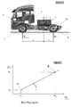
- the additional payload P L is shown as applied in correspondence of the baricenter of the additional weight applied on the chassis. With respect to the application point of the additional payload P L , the distances a and b of this indicated point from respectively the front axle 1, with mechanical suspension, and the rear axle 2, with pneumatic suspension, are known.
- the balance of the forces includes also the mass of the vehicle itself, therefore in order to obtain the actual load weighing on each axle it is necessary to consider that the additional payload is not the only load weighing on the vehicle axles, and that the empty weight of the vehicle itself, before the application of the additional payload P L , is not to be considered as applied in correspondence of the additional load.
- the weight of engine, transmission, chassis and cab is not to be considered as applied to the same point as the additional payload P L .
- a first measuring operation of the loads weighing on the axles may of course be carried out with the vehicle without any additional load, but it has not to be necessarily so and the two load conditions may be any.
- a second weighing operation in a different additional payload condition P L2 allows to read the value P HA2 from the load detection system of the rear pneumatic suspension and the value P L2 from the weighing machine, in order to identify the point B on the diagram of figure 2 .
- the determination of the points A and B for the interpolation of the characteristics of the line of figure 2 expressing the relation between P VA and P HA may be carried out only once for one single vehicle of a whole range of similar vehicles, and the relative data obtained this way may be input in the control unit 5 of the vehicle that already manages, in the systems known in the art, the reading of the load weighing on the pneumatic suspension, or it may be input in a provided control unit.
- the vehicle may be duly provided with a control unit 5 and a display system 6 of the load data processed by said control unit.
- the display system 6 may be duly provided with a display screen in order to show the value of the overall load of the vehicle.
- the control unit 5 can display the loads on each axle and can also sum them in order to give, with a simple and immediate operation, the information about the overall load of the vehicle. This information is very useful for the driver and makes unnecessary the use of a weighing machine in order to determine the load conditions, in case of a control by the police.
- the method for detecting the load according to the present invention may be easily and effectively used in all those cases wherein it is useful to count the goods, in case of a vehicle hauling goods. More in detail, it is known for example that in the field of the garbage collection, the firm which manages the collection is paid according to the quantity, expressed in weight, of garbage delivered to the garbage collection center. The evaluation of the quantity of material unloaded to the garbage collection or to the garbage incineration center are also useful to those managing the collection center or the incineration oven.
- scales or weighing machines for industrial vehicle have been used. This involves a loss of time for the weighing operations, but also the need to get such scales, which are expensive and very bulky.
- the method for detecting the load according to this invention in case it was used for detecting the load of a vehicle for garbage transport, would immediately make available the load data to the driver and to the garbage collection firm, making unnecessary the use of a scale. As a consequence, this results in a saving of time, because the weighing operation will not be carried out anymore, and in a saving of money, because it would be no longer necessary to buy and to maintain a truck weighing machine or to specially prepare some place devoted to said weighing machine and to the weighing operations of the load
- Another application field where the method for detecting the load according to the present invention would be extremely useful to quantify the goods loaded and unloaded by degrees, is the case of the distribution to different customers of a product carried in a tank.
- the calculation of the volume of the distributed product may be carried out by means of the measurement of the variation of the load weight.
- the indication of the load weighing on each axle and of the overall load may be used for the electronic control of functional parameters of the engine, of the transmission, of the electronic management of the braking system, besides the management of the tyre pressure according to the load.
- the method according to the present invention allows to calculate the load weighing on an axle with mechanical suspension by simply carrying out two weighing operation which may be carried out by the manufacturer before delivering the vehicle and only once for a whole range of similar vehicles. Once the necessary data have been obtained from the weighing operations, these may be input in a control unit of each vehicle without any need to repeat the weighing operations.
- the method according to the present invention allows to provide the driver with the indication about not only the load weighing on the axles equipped with mechanical suspensions, but also about the overall load of the vehicle by means of a rapid calculation, since it is possible to evaluate the load weighing on each axle and is therefore possible to simply sum the single loads in order to obtain the overall load of the vehicle.
- the variation may be removed by carrying out a calibration according to the procedures described above.
- a further purpose achieved by the method according to the present invention is that it allows to obtain the measure of the load weighing on the axles with mechanical suspensions without any need of measuring devices or additional control units, therefore without complicating the on-board electronic system and without adding any further component which would make the system, and therefore the vehicle, more expensive.
Landscapes
- Engineering & Computer Science (AREA)
- Mechanical Engineering (AREA)
- Physics & Mathematics (AREA)
- General Physics & Mathematics (AREA)
- Vehicle Body Suspensions (AREA)
Abstract
Description
- The present invention relates to a method for defining the load weighing on an axle with mechanical suspension of a vehicle provided with at least an axle with pneumatic suspension and load detection system, wherein the additional payload is proportionally distributed among the axles.
- As already known, the indication of the load weighing on the axles of a vehicle, in particular a heavy vehicle used for transportation, is useful for different purposes. First, it allows the driver to have a precise indication about the load conditions of the vehicle, about the proper distribution of the load on the vehicle and therefore about the overall load, which is useful in order to not exceed the maximum permissible load for that type of vehicle. As a matter of fact, each vehicle is type approved, in running order, for a determined maximum permissible load limiting both the overall load and the load on its different axles, and the law requires the driver to respect this maximum load limit. The indication of the overall load of the vehicle is therefore very useful for the driver, who can always know if the vehicle load is beneath the maximum permissible load limits.
- A further advantage of having the indication of the load weighing on each single axle is in the possibility for the manufacturer to verify if the vehicle has been properly used.
- As a matter of fact, structural failures of vehicle components occur quite frequently because of the use of the vehicle in overload conditions, and the manufacturer, who has to replace the damaged component, cannot objectively determine if the failure took place despite a use of the vehicle according to the recommendations of the manufacturer, or if the failure was caused by an improper use of the vehicle and therefore there is no reason to replace the component free of charge or to draw conclusions about the correct functionality of the component itself.
- Systems which can indicate the load weighing on an axle provided with pneumatic suspensions are known in the art. In these systems of the type known, one or more sensors, installed near the air springs of the pneumatic suspension, detect the existent pressure, which is proportional to the load, and send the data to a control unit which calculates the load from the pressure value.
- The systems known in the art, however, can indicate the load weighing only on the axles provided with pneumatic suspensions.
- In many cases, one single axle, the rear axle of the vehicle, is provided with pneumatic suspensions, while usually the front axle is provided with mechanical suspensions, which are not provided of any device for the measurement of the load weighing on the axle itself. In these situations, it is impossible to determine the load weighing on the front axle and therefore, which is not less important, it is impossible to determine the value of the overall load, without having to weigh the vehicle with the appropriate weighing machines.
- The main task of the present invention is to provide a calculation method for defining the load weighing on an axle with mechanical suspension wherein the additional payload is proportionally distributed among the axes of a vehicle provided with at least a pneumatic suspension and a load detection system.
- In the scope of this task, the purpose of the present invention is to provide a calculation method allowing to know the load weighing on each axle, as to avoid the accidental overloading of the axle itself.
- A further purpose of the present invention is to provide a calculation method allowing to know the overall load weighing on the vehicle, without having to weigh the vehicle itself. The weighing machines of heavy vehicles are often hardly available, and the weighing operations, however, represent a loss of time for the carrier.
- This task and these and other purposes that are explained below are achieved by a method for detecting the load weighing on a vehicle axle with mechanical suspension, particularly for vehicles used for transportation comprising at least a second axle with pneumatic suspension provided with sensor and system for detecting the load weighing on said second axle, and wherein the additional payload on the vehicle is proportionally distributed among said axles,
characterized in that it comprises at least a first and a second step for determining the additional payload and a following calculation step for determining the relation existing among the loads weighing on the axles. - Further characteristics and advantages of the present invention will become clear from the following detailed description, that is merely illustrative and not limitative and is shown in the figures that are attached hereto, in which:
-
figure 1 schematically shows a vehicle with the indication of the loads weighing on the chassis and on the axles; -
figure 2 shows a diagram illustrative of the mathematical relation existing among the forces acting on the axles. - On a vehicle, for example a vehicle similar to that represented in
figure 1 , the additional payload is applied on the chassis in a symmetrical way. - The additional payload PL is shown as applied in correspondence of the baricenter of the additional weight applied on the chassis. With respect to the application point of the additional payload PL, the distances a and b of this indicated point from respectively the
front axle 1, with mechanical suspension, and therear axle 2, with pneumatic suspension, are known. - The mathematical relation among the acting forces is derived by a balance of the forces themselves and brings to the following relation:

- Obviously, besides the additional payload PL, the balance of the forces includes also the mass of the vehicle itself, therefore in order to obtain the actual load weighing on each axle it is necessary to consider that the additional payload is not the only load weighing on the vehicle axles, and that the empty weight of the vehicle itself, before the application of the additional payload PL, is not to be considered as applied in correspondence of the additional load. The weight of engine, transmission, chassis and cab is not to be considered as applied to the same point as the additional payload PL.
- Therefore, after having determined, by means of the balance of the forces, that the distribution of the additional payload PL between the front and the rear axle is of the linear type, since it is connected to the arms a and b, in order to calculate the ratio between the two loads weighing on the axles it is necessary to adopt an empirical method based on the measurement of the load weighing on the axle in at least two different load conditions, that is with two different values of the additional payload PL.
- For a greater convenience, a first measuring operation of the loads weighing on the axles may of course be carried out with the vehicle without any additional load, but it has not to be necessarily so and the two load conditions may be any.
- Therefore, as said, in order to find the linear relation connecting the values of the loads weighing on the axles PVA and PHA when the additional payload PL varies, first it is necessary to weigh the vehicle with an additional payload value PL1, which may be any, including zero, by reading the values PHA1 weighing on the rear axle, obtained by means of a sensor 4 suitable for detecting the pressure and a
control unit 5 which calculates the load weighing on a pneumatic suspension, according to what is already known in the art. The value of the load PVA1 weighing on the front axle, instead, may be obtained by the weighing on an appropriate weighing machine. - Once the values PVA1 and PHA1 are known in a first loading condition, empty or with any PL1, it is possible to identify a first point A on the diagram, which connects PHA and PVA in
figure 2 . - A second weighing operation in a different additional payload condition PL2 allows to read the value PHA2 from the load detection system of the rear pneumatic suspension and the value PL2 from the weighing machine, in order to identify the point B on the diagram of
figure 2 . Once the point A and B on the diagram are known, and expecting that the load distribution on the axles is of the linear type according to what explained above about the proportional distribution of the load on the axles, it is possible to use a linear interpolation in order to draw a line connecting the two points, A and B, and to determine its slope. - Once the angle α defining the slope of this line is known, for each value detected by the sensor 4 which detects the load weighing on the pneumatic suspension of the
rear axle 2, PHA, it is possible to calculate the value of the load weighing on the axle withmechanical suspension 1 by means of the relation:
- The determination of the points A and B for the interpolation of the characteristics of the line of
figure 2 expressing the relation between PVA and PHA may be carried out only once for one single vehicle of a whole range of similar vehicles, and the relative data obtained this way may be input in thecontrol unit 5 of the vehicle that already manages, in the systems known in the art, the reading of the load weighing on the pneumatic suspension, or it may be input in a provided control unit. - According to what is shown in
figure 1 , the vehicle may be duly provided with acontrol unit 5 and adisplay system 6 of the load data processed by said control unit. - Moreover, the
display system 6 may be duly provided with a display screen in order to show the value of the overall load of the vehicle. In order to process this data, once thecontrol unit 6 has calculated the load weighing on each single axle by means of a direct detection in the case of pneumatic suspensions, or by means of the calculation described here in the case of mechanical suspension, thecontrol unit 5 can display the loads on each axle and can also sum them in order to give, with a simple and immediate operation, the information about the overall load of the vehicle. This information is very useful for the driver and makes unnecessary the use of a weighing machine in order to determine the load conditions, in case of a control by the police. - In particular, the method for detecting the load according to the present invention may be easily and effectively used in all those cases wherein it is useful to count the goods, in case of a vehicle hauling goods. More in detail, it is known for example that in the field of the garbage collection, the firm which manages the collection is paid according to the quantity, expressed in weight, of garbage delivered to the garbage collection center. The evaluation of the quantity of material unloaded to the garbage collection or to the garbage incineration center are also useful to those managing the collection center or the incineration oven. At present, in order to quantify the load of a vehicle carrying out the garbage collection, scales or weighing machines for industrial vehicle have been used. This involves a loss of time for the weighing operations, but also the need to get such scales, which are expensive and very bulky.
- The method for detecting the load according to this invention, in case it was used for detecting the load of a vehicle for garbage transport, would immediately make available the load data to the driver and to the garbage collection firm, making unnecessary the use of a scale. As a consequence, this results in a saving of time, because the weighing operation will not be carried out anymore, and in a saving of money, because it would be no longer necessary to buy and to maintain a truck weighing machine or to specially prepare some place devoted to said weighing machine and to the weighing operations of the load
- Another application field where the method for detecting the load according to the present invention would be extremely useful to quantify the goods loaded and unloaded by degrees, is the case of the distribution to different customers of a product carried in a tank. The calculation of the volume of the distributed product may be carried out by means of the measurement of the variation of the load weight.
In several other application fields it may be very useful to know the value of the carried load, and the method according to this invention fulfils the need to make the overall load value immediately available to the driver.
For example, the indication of the load weighing on each axle and of the overall load may be used for the electronic control of functional parameters of the engine, of the transmission, of the electronic management of the braking system, besides the management of the tyre pressure according to the load. - Therefore several other application fields may exist.
- Therefore it has been shown that the method for defining the load weighing on an axle with mechanical suspension according to the present invention achieves the purpose and the objects proposed.
- In particular, it has been shown that the method according to the present invention allows to calculate the load weighing on an axle with mechanical suspension by simply carrying out two weighing operation which may be carried out by the manufacturer before delivering the vehicle and only once for a whole range of similar vehicles. Once the necessary data have been obtained from the weighing operations, these may be input in a control unit of each vehicle without any need to repeat the weighing operations.
- More in detail, the method according to the present invention allows to provide the driver with the indication about not only the load weighing on the axles equipped with mechanical suspensions, but also about the overall load of the vehicle by means of a rapid calculation, since it is possible to evaluate the load weighing on each axle and is therefore possible to simply sum the single loads in order to obtain the overall load of the vehicle.
- In case a variation of the characteristics of the mechanical suspension influences the preciseness of the system, the variation may be removed by carrying out a calibration according to the procedures described above.
- A further purpose achieved by the method according to the present invention is that it allows to obtain the measure of the load weighing on the axles with mechanical suspensions without any need of measuring devices or additional control units, therefore without complicating the on-board electronic system and without adding any further component which would make the system, and therefore the vehicle, more expensive.
- It will be apparent to the person skilled in the art that various modifications can be conceived and reduced to practice without departing from the scope of the invention.
- Therefore, the scope of the claims is not limited to the illustrations or the preferred embodiments shown in the description as an example, but rather the claims include all the patentable novelties deriving from the present invention, including all the equivalent embodiments for a person skilled in the art.
Claims (11)
- Method for detecting the load (PVA) weighing on a first vehicle axle (1) with mechanical suspension, particularly for vehicles used for transportation comprising at least a second axle (2) with pneumatic suspension provided with sensor (4) for the detection of the load (PHA) weighing on said second (2) axle and a control unit (5) and wherein the additional payload (PL) on the vehicle is proportionally distributed among said axles (1, 2), characterized in that it comprises at least a first and a second step for detecting the loads (PHA1, PVA1, PHA2, PVA2) weighing on the axles (1, 2) with any two different values of the additional payload (PL) and a following calculation step for determining the relation existing among the loads (PVA, PHA) weighing on the axles (1, 2).
- Method according to the previous claim, characterized in that said steps for detecting the loads (PHA1, PVA1, PHA2, PVA2) weighing on the axles (1, 2) comprise the following stages:- detect by means of said sensor (4) of the pneumatic suspension and by means of said control unit (5) the load (PHA1) weighing on said second axle (2) provided with pneumatic suspension in a first load condition of the vehicle, with any value of additional payload (PL1);- carry out a first weighing operation of the vehicle in order to determine the value of the load (PVA1) weighing on said first axle (1) provided with mechanical suspension in said first load condition;- load the vehicle with an additional payload (PL2) different from the previous (PL1);- detect by means of said sensor (4) and said control unit (5) the load (PHA2) weighing on said second axle (2) in said second load condition;- carry out a second weighing operation of the vehicle in order to determine the value of the load (PVA2) weighing on said first axle (1) provided with mechanical suspension in said second load condition;
- Method according to any of the previous claims, characterized in that said calculation step for determining the relation among the loads weighing on the axles (1, 2) comprise a linear interpolation calculation between at least two point (A, B) each of said points being representative of one of said two load condition (PVA1, PHA1, PVA2, PHA2) in order to determine the relation PVA/PHA.
- Method according to the previous claim, characterized in that said interpolation step comprises a linear interpolation between the point A representative of the first load condition (PHA1, PVA1) and the point B representative of the second load condition (PHA2, PHA2) as to determine the ratio PVA/PHA equal to the tangent of the angle α, angular coefficient of the line passing through A and B on a diagram PHA, PVA.
- Method according to one or more previous claims, characterized in that it comprises a step for determining the value of the load (PVA) weighing on said first axle (1) with mechanical suspension by detecting the load value (PHA) by means of said sensor (4) and said control unit (5) and multiplying said value by the tangent of the angle α previously determined.
- Method according to any of the previous claims, characterized in that said calculation step is carried out by an electronic control unit (5).
- Method for the calibration of an electronic control unit (5) according to one or more previous claims.
- Electronic control unit (5) characterized in that it comprises a program for the calculation of the load (PVA) weighing on a first axle (1) with mechanical suspension in function of the load (PHA) weighing on a second axle (2) provided with a sensor (4) for the detection of the load weighing on said axle.
- Electronic control unit (5) according to the previous claim, characterized in that said calculation program carries out the calculation according to one of the claims from 3 to 5.
- Vehicle comprising an electronic control unit (5) according to any of the previous claims 8 or 9.
- Vehicle for hauling goods, in particular for hauling garbage, characterized in that it comprises an electronic control unit (5) suitable for carrying out the method for detecting the load according to one or more previous claims.
Priority Applications (2)
| Application Number | Priority Date | Filing Date | Title |
|---|---|---|---|
| EP08102997.7A EP2105717B1 (en) | 2008-03-27 | 2008-03-27 | Method for defining the load weighing on an axle with mechanical suspension in a vehicle provided with at least an axle with pneumatic suspension provided with load detection system |
| ES08102997T ES2857053T3 (en) | 2008-03-27 | 2008-03-27 | Method for defining the load on an axle with mechanical suspension in a vehicle provided with at least one axle with air suspension provided with a load sensing system |
Applications Claiming Priority (1)
| Application Number | Priority Date | Filing Date | Title |
|---|---|---|---|
| EP08102997.7A EP2105717B1 (en) | 2008-03-27 | 2008-03-27 | Method for defining the load weighing on an axle with mechanical suspension in a vehicle provided with at least an axle with pneumatic suspension provided with load detection system |
Publications (2)
| Publication Number | Publication Date |
|---|---|
| EP2105717A1 true EP2105717A1 (en) | 2009-09-30 |
| EP2105717B1 EP2105717B1 (en) | 2020-12-16 |
Family
ID=39708364
Family Applications (1)
| Application Number | Title | Priority Date | Filing Date |
|---|---|---|---|
| EP08102997.7A Not-in-force EP2105717B1 (en) | 2008-03-27 | 2008-03-27 | Method for defining the load weighing on an axle with mechanical suspension in a vehicle provided with at least an axle with pneumatic suspension provided with load detection system |
Country Status (2)
| Country | Link |
|---|---|
| EP (1) | EP2105717B1 (en) |
| ES (1) | ES2857053T3 (en) |
Cited By (3)
| Publication number | Priority date | Publication date | Assignee | Title |
|---|---|---|---|---|
| CN107330490A (en) * | 2017-06-29 | 2017-11-07 | 杭州金株环境科技有限公司 | A kind of rubbish from cooking processing Measurement and Administration System and its control method |
| US20210237574A1 (en) * | 2020-02-05 | 2021-08-05 | Paccar Inc | Dynamic chassis and tire status indications |
| US11820372B2 (en) | 2019-09-18 | 2023-11-21 | Industries N.R.C. Inc | Tow weight evaluation system for wreckers |
Citations (3)
| Publication number | Priority date | Publication date | Assignee | Title |
|---|---|---|---|---|
| DE10027300C1 (en) * | 2000-06-05 | 2001-09-06 | H Gmbh Sa | Mobile hand operated unit with process computer, operating and indicating elements, has data transmission element as functional component of load measuring unit provided at commercial vehicle loading sensors |
| WO2003044471A2 (en) | 2001-10-19 | 2003-05-30 | Scania Cv Ab (Publ) | Load calculating system for a goods vehicle |
| WO2006046903A1 (en) | 2004-10-29 | 2006-05-04 | Volvo Lastvagnar Ab | A method and a system for determining the load transferred from a semi-trailer to a first axle of a towing vehicle |
-
2008
- 2008-03-27 EP EP08102997.7A patent/EP2105717B1/en not_active Not-in-force
- 2008-03-27 ES ES08102997T patent/ES2857053T3/en active Active
Patent Citations (3)
| Publication number | Priority date | Publication date | Assignee | Title |
|---|---|---|---|---|
| DE10027300C1 (en) * | 2000-06-05 | 2001-09-06 | H Gmbh Sa | Mobile hand operated unit with process computer, operating and indicating elements, has data transmission element as functional component of load measuring unit provided at commercial vehicle loading sensors |
| WO2003044471A2 (en) | 2001-10-19 | 2003-05-30 | Scania Cv Ab (Publ) | Load calculating system for a goods vehicle |
| WO2006046903A1 (en) | 2004-10-29 | 2006-05-04 | Volvo Lastvagnar Ab | A method and a system for determining the load transferred from a semi-trailer to a first axle of a towing vehicle |
Cited By (5)
| Publication number | Priority date | Publication date | Assignee | Title |
|---|---|---|---|---|
| CN107330490A (en) * | 2017-06-29 | 2017-11-07 | 杭州金株环境科技有限公司 | A kind of rubbish from cooking processing Measurement and Administration System and its control method |
| CN107330490B (en) * | 2017-06-29 | 2019-12-27 | 杭州金株环境科技有限公司 | Kitchen waste treatment weighing management system and control method thereof |
| US11820372B2 (en) | 2019-09-18 | 2023-11-21 | Industries N.R.C. Inc | Tow weight evaluation system for wreckers |
| US20210237574A1 (en) * | 2020-02-05 | 2021-08-05 | Paccar Inc | Dynamic chassis and tire status indications |
| US11623519B2 (en) * | 2020-02-05 | 2023-04-11 | Paccar Inc. | Dynamic chassis and tire status indications |
Also Published As
| Publication number | Publication date |
|---|---|
| ES2857053T3 (en) | 2021-09-28 |
| EP2105717B1 (en) | 2020-12-16 |
Similar Documents
| Publication | Publication Date | Title |
|---|---|---|
| US5182712A (en) | Dynamic payload monitor | |
| US6449582B1 (en) | Vehicle weight and cargo load determination using tire pressure | |
| US6363331B1 (en) | Weight distribution monitor | |
| AU2015202184B2 (en) | Weighing system for a front-end-loading waste-hauling vehicle | |
| EP2537007B1 (en) | System and method for monitoring vehicle mass tamper events | |
| EP0540741A1 (en) | System for measuring carrying weight of vehicle | |
| US12275285B2 (en) | Method for determining an axle load on a mechanically suspended vehicle | |
| US6137066A (en) | Weighing device | |
| US5912439A (en) | System and method for safety control in vehicles | |
| EP2105717B1 (en) | Method for defining the load weighing on an axle with mechanical suspension in a vehicle provided with at least an axle with pneumatic suspension provided with load detection system | |
| WO2021150376A1 (en) | Method and apparatus for single draft, static and dynamic vehicle weighing using the same weight scale | |
| US6307164B1 (en) | Pneumatic load measuring device for vehicles | |
| EP2075145A1 (en) | Method and system for detecting the load of a vehicle equipped with non-pneumatic suspensions | |
| US6646210B1 (en) | Device and method for detecting the weight of the useful load of a commercial vehicle by means of a vertical sensor | |
| KR101769295B1 (en) | Monitoring system of weight in motion | |
| EP0218466A1 (en) | Vehicle load monitoring system | |
| KR20000011058A (en) | Measuring system of vehicle load figure | |
| CN106289470A (en) | A kind of truck combination vehicle-mounted weighing system and Weighing method | |
| CN106644011A (en) | On-board weighing system | |
| JPH10267739A (en) | Weight measuring method for vehicle and its device | |
| WO2006080611A1 (en) | Method and system for controlling overloaded | |
| Parigot et al. | Development of an Embedded Weighing System for Semi-Trailers Based on Hall Effect Sensor | |
| EP2629070A1 (en) | Device and method for determination of load supported by a bogie configuration of a vehicle | |
| JPH1130550A (en) | Overload detecting apparatus for vehicle | |
| FI119829B (en) | Device and method of weighing a vehicle |
Legal Events
| Date | Code | Title | Description |
|---|---|---|---|
| PUAI | Public reference made under article 153(3) epc to a published international application that has entered the european phase |
Free format text: ORIGINAL CODE: 0009012 |
|
| AK | Designated contracting states |
Kind code of ref document: A1 Designated state(s): AT BE BG CH CY CZ DE DK EE ES FI FR GB GR HR HU IE IS IT LI LT LU LV MC MT NL NO PL PT RO SE SI SK TR |
|
| AX | Request for extension of the european patent |
Extension state: AL BA MK RS |
|
| 17P | Request for examination filed |
Effective date: 20100325 |
|
| AKX | Designation fees paid |
Designated state(s): AT BE BG CH CY CZ DE DK EE ES FI FR GB GR HR HU IE IS IT LI LT LU LV MC MT NL NO PL PT RO SE SI SK TR |
|
| 17Q | First examination report despatched |
Effective date: 20110921 |
|
| STAA | Information on the status of an ep patent application or granted ep patent |
Free format text: STATUS: EXAMINATION IS IN PROGRESS |
|
| GRAJ | Information related to disapproval of communication of intention to grant by the applicant or resumption of examination proceedings by the epo deleted |
Free format text: ORIGINAL CODE: EPIDOSDIGR1 |
|
| GRAP | Despatch of communication of intention to grant a patent |
Free format text: ORIGINAL CODE: EPIDOSNIGR1 |
|
| GRAP | Despatch of communication of intention to grant a patent |
Free format text: ORIGINAL CODE: EPIDOSNIGR1 |
|
| STAA | Information on the status of an ep patent application or granted ep patent |
Free format text: STATUS: GRANT OF PATENT IS INTENDED |
|
| RIC1 | Information provided on ipc code assigned before grant |
Ipc: B60G 17/019 20060101ALI20200618BHEP Ipc: B60G 17/017 20060101ALI20200618BHEP Ipc: G01G 19/10 20060101AFI20200618BHEP |
|
| INTG | Intention to grant announced |
Effective date: 20200721 |
|
| GRAS | Grant fee paid |
Free format text: ORIGINAL CODE: EPIDOSNIGR3 |
|
| GRAA | (expected) grant |
Free format text: ORIGINAL CODE: 0009210 |
|
| STAA | Information on the status of an ep patent application or granted ep patent |
Free format text: STATUS: THE PATENT HAS BEEN GRANTED |
|
| AK | Designated contracting states |
Kind code of ref document: B1 Designated state(s): AT BE BG CH CY CZ DE DK EE ES FI FR GB GR HR HU IE IS IT LI LT LU LV MC MT NL NO PL PT RO SE SI SK TR |
|
| REG | Reference to a national code |
Ref country code: GB Ref legal event code: FG4D |
|
| REG | Reference to a national code |
Ref country code: DE Ref legal event code: R096 Ref document number: 602008063569 Country of ref document: DE |
|
| REG | Reference to a national code |
Ref country code: IE Ref legal event code: FG4D |
|
| REG | Reference to a national code |
Ref country code: AT Ref legal event code: REF Ref document number: 1346032 Country of ref document: AT Kind code of ref document: T Effective date: 20210115 |
|
| PG25 | Lapsed in a contracting state [announced via postgrant information from national office to epo] |
Ref country code: GR Free format text: LAPSE BECAUSE OF FAILURE TO SUBMIT A TRANSLATION OF THE DESCRIPTION OR TO PAY THE FEE WITHIN THE PRESCRIBED TIME-LIMIT Effective date: 20210317 Ref country code: FI Free format text: LAPSE BECAUSE OF FAILURE TO SUBMIT A TRANSLATION OF THE DESCRIPTION OR TO PAY THE FEE WITHIN THE PRESCRIBED TIME-LIMIT Effective date: 20201216 Ref country code: NO Free format text: LAPSE BECAUSE OF FAILURE TO SUBMIT A TRANSLATION OF THE DESCRIPTION OR TO PAY THE FEE WITHIN THE PRESCRIBED TIME-LIMIT Effective date: 20210316 |
|
| REG | Reference to a national code |
Ref country code: AT Ref legal event code: MK05 Ref document number: 1346032 Country of ref document: AT Kind code of ref document: T Effective date: 20201216 |
|
| REG | Reference to a national code |
Ref country code: NL Ref legal event code: MP Effective date: 20201216 |
|
| PG25 | Lapsed in a contracting state [announced via postgrant information from national office to epo] |
Ref country code: BG Free format text: LAPSE BECAUSE OF FAILURE TO SUBMIT A TRANSLATION OF THE DESCRIPTION OR TO PAY THE FEE WITHIN THE PRESCRIBED TIME-LIMIT Effective date: 20210316 Ref country code: SE Free format text: LAPSE BECAUSE OF FAILURE TO SUBMIT A TRANSLATION OF THE DESCRIPTION OR TO PAY THE FEE WITHIN THE PRESCRIBED TIME-LIMIT Effective date: 20201216 Ref country code: LV Free format text: LAPSE BECAUSE OF FAILURE TO SUBMIT A TRANSLATION OF THE DESCRIPTION OR TO PAY THE FEE WITHIN THE PRESCRIBED TIME-LIMIT Effective date: 20201216 |
|
| PG25 | Lapsed in a contracting state [announced via postgrant information from national office to epo] |
Ref country code: HR Free format text: LAPSE BECAUSE OF FAILURE TO SUBMIT A TRANSLATION OF THE DESCRIPTION OR TO PAY THE FEE WITHIN THE PRESCRIBED TIME-LIMIT Effective date: 20201216 Ref country code: NL Free format text: LAPSE BECAUSE OF FAILURE TO SUBMIT A TRANSLATION OF THE DESCRIPTION OR TO PAY THE FEE WITHIN THE PRESCRIBED TIME-LIMIT Effective date: 20201216 |
|
| REG | Reference to a national code |
Ref country code: LT Ref legal event code: MG9D |
|
| PG25 | Lapsed in a contracting state [announced via postgrant information from national office to epo] |
Ref country code: LT Free format text: LAPSE BECAUSE OF FAILURE TO SUBMIT A TRANSLATION OF THE DESCRIPTION OR TO PAY THE FEE WITHIN THE PRESCRIBED TIME-LIMIT Effective date: 20201216 Ref country code: CZ Free format text: LAPSE BECAUSE OF FAILURE TO SUBMIT A TRANSLATION OF THE DESCRIPTION OR TO PAY THE FEE WITHIN THE PRESCRIBED TIME-LIMIT Effective date: 20201216 Ref country code: EE Free format text: LAPSE BECAUSE OF FAILURE TO SUBMIT A TRANSLATION OF THE DESCRIPTION OR TO PAY THE FEE WITHIN THE PRESCRIBED TIME-LIMIT Effective date: 20201216 Ref country code: RO Free format text: LAPSE BECAUSE OF FAILURE TO SUBMIT A TRANSLATION OF THE DESCRIPTION OR TO PAY THE FEE WITHIN THE PRESCRIBED TIME-LIMIT Effective date: 20201216 Ref country code: PT Free format text: LAPSE BECAUSE OF FAILURE TO SUBMIT A TRANSLATION OF THE DESCRIPTION OR TO PAY THE FEE WITHIN THE PRESCRIBED TIME-LIMIT Effective date: 20210416 Ref country code: SK Free format text: LAPSE BECAUSE OF FAILURE TO SUBMIT A TRANSLATION OF THE DESCRIPTION OR TO PAY THE FEE WITHIN THE PRESCRIBED TIME-LIMIT Effective date: 20201216 |
|
| PG25 | Lapsed in a contracting state [announced via postgrant information from national office to epo] |
Ref country code: PL Free format text: LAPSE BECAUSE OF FAILURE TO SUBMIT A TRANSLATION OF THE DESCRIPTION OR TO PAY THE FEE WITHIN THE PRESCRIBED TIME-LIMIT Effective date: 20201216 Ref country code: AT Free format text: LAPSE BECAUSE OF FAILURE TO SUBMIT A TRANSLATION OF THE DESCRIPTION OR TO PAY THE FEE WITHIN THE PRESCRIBED TIME-LIMIT Effective date: 20201216 |
|
| REG | Reference to a national code |
Ref country code: DE Ref legal event code: R097 Ref document number: 602008063569 Country of ref document: DE |
|
| REG | Reference to a national code |
Ref country code: ES Ref legal event code: FG2A Ref document number: 2857053 Country of ref document: ES Kind code of ref document: T3 Effective date: 20210928 |
|
| PG25 | Lapsed in a contracting state [announced via postgrant information from national office to epo] |
Ref country code: IS Free format text: LAPSE BECAUSE OF FAILURE TO SUBMIT A TRANSLATION OF THE DESCRIPTION OR TO PAY THE FEE WITHIN THE PRESCRIBED TIME-LIMIT Effective date: 20210416 |
|
| PLBE | No opposition filed within time limit |
Free format text: ORIGINAL CODE: 0009261 |
|
| STAA | Information on the status of an ep patent application or granted ep patent |
Free format text: STATUS: NO OPPOSITION FILED WITHIN TIME LIMIT |
|
| PG25 | Lapsed in a contracting state [announced via postgrant information from national office to epo] |
Ref country code: MC Free format text: LAPSE BECAUSE OF FAILURE TO SUBMIT A TRANSLATION OF THE DESCRIPTION OR TO PAY THE FEE WITHIN THE PRESCRIBED TIME-LIMIT Effective date: 20201216 |
|
| REG | Reference to a national code |
Ref country code: CH Ref legal event code: PL |
|
| 26N | No opposition filed |
Effective date: 20210917 |
|
| GBPC | Gb: european patent ceased through non-payment of renewal fee |
Effective date: 20210327 |
|
| PG25 | Lapsed in a contracting state [announced via postgrant information from national office to epo] |
Ref country code: DK Free format text: LAPSE BECAUSE OF FAILURE TO SUBMIT A TRANSLATION OF THE DESCRIPTION OR TO PAY THE FEE WITHIN THE PRESCRIBED TIME-LIMIT Effective date: 20201216 |
|
| REG | Reference to a national code |
Ref country code: BE Ref legal event code: MM Effective date: 20210331 |
|
| PG25 | Lapsed in a contracting state [announced via postgrant information from national office to epo] |
Ref country code: CH Free format text: LAPSE BECAUSE OF NON-PAYMENT OF DUE FEES Effective date: 20210331 Ref country code: LU Free format text: LAPSE BECAUSE OF NON-PAYMENT OF DUE FEES Effective date: 20210327 Ref country code: LI Free format text: LAPSE BECAUSE OF NON-PAYMENT OF DUE FEES Effective date: 20210331 Ref country code: GB Free format text: LAPSE BECAUSE OF NON-PAYMENT OF DUE FEES Effective date: 20210327 Ref country code: IE Free format text: LAPSE BECAUSE OF NON-PAYMENT OF DUE FEES Effective date: 20210327 |
|
| PG25 | Lapsed in a contracting state [announced via postgrant information from national office to epo] |
Ref country code: SI Free format text: LAPSE BECAUSE OF FAILURE TO SUBMIT A TRANSLATION OF THE DESCRIPTION OR TO PAY THE FEE WITHIN THE PRESCRIBED TIME-LIMIT Effective date: 20201216 |
|
| PG25 | Lapsed in a contracting state [announced via postgrant information from national office to epo] |
Ref country code: IS Free format text: LAPSE BECAUSE OF FAILURE TO SUBMIT A TRANSLATION OF THE DESCRIPTION OR TO PAY THE FEE WITHIN THE PRESCRIBED TIME-LIMIT Effective date: 20210416 |
|
| PG25 | Lapsed in a contracting state [announced via postgrant information from national office to epo] |
Ref country code: BE Free format text: LAPSE BECAUSE OF NON-PAYMENT OF DUE FEES Effective date: 20210331 |
|
| PG25 | Lapsed in a contracting state [announced via postgrant information from national office to epo] |
Ref country code: HU Free format text: LAPSE BECAUSE OF FAILURE TO SUBMIT A TRANSLATION OF THE DESCRIPTION OR TO PAY THE FEE WITHIN THE PRESCRIBED TIME-LIMIT; INVALID AB INITIO Effective date: 20080327 Ref country code: CY Free format text: LAPSE BECAUSE OF FAILURE TO SUBMIT A TRANSLATION OF THE DESCRIPTION OR TO PAY THE FEE WITHIN THE PRESCRIBED TIME-LIMIT Effective date: 20201216 |
|
| P01 | Opt-out of the competence of the unified patent court (upc) registered |
Effective date: 20230523 |
|
| PGFP | Annual fee paid to national office [announced via postgrant information from national office to epo] |
Ref country code: DE Payment date: 20240328 Year of fee payment: 17 |
|
| PGFP | Annual fee paid to national office [announced via postgrant information from national office to epo] |
Ref country code: IT Payment date: 20240315 Year of fee payment: 17 Ref country code: FR Payment date: 20240326 Year of fee payment: 17 |
|
| PG25 | Lapsed in a contracting state [announced via postgrant information from national office to epo] |
Ref country code: TR Free format text: LAPSE BECAUSE OF FAILURE TO SUBMIT A TRANSLATION OF THE DESCRIPTION OR TO PAY THE FEE WITHIN THE PRESCRIBED TIME-LIMIT Effective date: 20201216 |
|
| PGFP | Annual fee paid to national office [announced via postgrant information from national office to epo] |
Ref country code: ES Payment date: 20240412 Year of fee payment: 17 |
|
| PG25 | Lapsed in a contracting state [announced via postgrant information from national office to epo] |
Ref country code: MT Free format text: LAPSE BECAUSE OF FAILURE TO SUBMIT A TRANSLATION OF THE DESCRIPTION OR TO PAY THE FEE WITHIN THE PRESCRIBED TIME-LIMIT Effective date: 20201216 |
|
| REG | Reference to a national code |
Ref country code: DE Ref legal event code: R119 Ref document number: 602008063569 Country of ref document: DE |
|
| PG25 | Lapsed in a contracting state [announced via postgrant information from national office to epo] |
Ref country code: DE Free format text: LAPSE BECAUSE OF NON-PAYMENT OF DUE FEES Effective date: 20251001 |
|
| PG25 | Lapsed in a contracting state [announced via postgrant information from national office to epo] |
Ref country code: IT Free format text: LAPSE BECAUSE OF NON-PAYMENT OF DUE FEES Effective date: 20250327 Ref country code: FR Free format text: LAPSE BECAUSE OF NON-PAYMENT OF DUE FEES Effective date: 20250331 |
|
| REG | Reference to a national code |
Ref country code: ES Ref legal event code: FD2A Effective date: 20260504 |