EP2105692A1 - Stopping member for heat insulating layer, firing furnace, and method for manufacturing honeycomb structured body using firing furnace. - Google Patents
Stopping member for heat insulating layer, firing furnace, and method for manufacturing honeycomb structured body using firing furnace. Download PDFInfo
- Publication number
- EP2105692A1 EP2105692A1 EP08291127A EP08291127A EP2105692A1 EP 2105692 A1 EP2105692 A1 EP 2105692A1 EP 08291127 A EP08291127 A EP 08291127A EP 08291127 A EP08291127 A EP 08291127A EP 2105692 A1 EP2105692 A1 EP 2105692A1
- Authority
- EP
- European Patent Office
- Prior art keywords
- heat insulating
- insulating layer
- stopping member
- firing furnace
- stopper
- Prior art date
- Legal status (The legal status is an assumption and is not a legal conclusion. Google has not performed a legal analysis and makes no representation as to the accuracy of the status listed.)
- Withdrawn
Links
- 238000010304 firing Methods 0.000 title claims abstract description 111
- 238000004519 manufacturing process Methods 0.000 title claims description 55
- 238000000034 method Methods 0.000 title claims description 37
- 239000000919 ceramic Substances 0.000 claims abstract description 117
- OKTJSMMVPCPJKN-UHFFFAOYSA-N Carbon Chemical compound [C] OKTJSMMVPCPJKN-UHFFFAOYSA-N 0.000 claims description 31
- 229910052799 carbon Inorganic materials 0.000 claims description 30
- 239000000463 material Substances 0.000 claims description 20
- 229920000049 Carbon (fiber) Polymers 0.000 claims description 12
- 239000004917 carbon fiber Substances 0.000 claims description 12
- HBMJWWWQQXIZIP-UHFFFAOYSA-N silicon carbide Chemical compound [Si+]#[C-] HBMJWWWQQXIZIP-UHFFFAOYSA-N 0.000 claims description 12
- 229910052751 metal Inorganic materials 0.000 claims description 11
- 239000002184 metal Substances 0.000 claims description 11
- 229910010271 silicon carbide Inorganic materials 0.000 claims description 10
- VNWKTOKETHGBQD-UHFFFAOYSA-N methane Chemical compound C VNWKTOKETHGBQD-UHFFFAOYSA-N 0.000 claims description 9
- 239000000843 powder Substances 0.000 claims description 8
- 239000010410 layer Substances 0.000 description 241
- 239000007789 gas Substances 0.000 description 19
- 230000008439 repair process Effects 0.000 description 19
- 238000010438 heat treatment Methods 0.000 description 15
- 210000004027 cell Anatomy 0.000 description 12
- 230000008569 process Effects 0.000 description 11
- 239000000203 mixture Substances 0.000 description 10
- 239000000853 adhesive Substances 0.000 description 7
- 230000001070 adhesive effect Effects 0.000 description 7
- 238000001035 drying Methods 0.000 description 7
- 239000003566 sealing material Substances 0.000 description 7
- 210000002421 cell wall Anatomy 0.000 description 6
- 229910052575 non-oxide ceramic Inorganic materials 0.000 description 6
- 239000011225 non-oxide ceramic Substances 0.000 description 6
- 239000012790 adhesive layer Substances 0.000 description 5
- 238000006243 chemical reaction Methods 0.000 description 5
- 239000012535 impurity Substances 0.000 description 5
- 230000002093 peripheral effect Effects 0.000 description 5
- XUIMIQQOPSSXEZ-UHFFFAOYSA-N Silicon Chemical compound [Si] XUIMIQQOPSSXEZ-UHFFFAOYSA-N 0.000 description 4
- 239000012298 atmosphere Substances 0.000 description 4
- 239000003575 carbonaceous material Substances 0.000 description 4
- 239000003054 catalyst Substances 0.000 description 4
- 239000011810 insulating material Substances 0.000 description 4
- 150000004767 nitrides Chemical class 0.000 description 4
- 239000002245 particle Substances 0.000 description 4
- 229910052710 silicon Inorganic materials 0.000 description 4
- 239000010703 silicon Substances 0.000 description 4
- 230000009471 action Effects 0.000 description 3
- 239000011230 binding agent Substances 0.000 description 3
- 230000008859 change Effects 0.000 description 3
- 239000000470 constituent Substances 0.000 description 3
- 238000001125 extrusion Methods 0.000 description 3
- 238000007254 oxidation reaction Methods 0.000 description 3
- 238000007789 sealing Methods 0.000 description 3
- XLYOFNOQVPJJNP-UHFFFAOYSA-N water Substances O XLYOFNOQVPJJNP-UHFFFAOYSA-N 0.000 description 3
- XKRFYHLGVUSROY-UHFFFAOYSA-N Argon Chemical compound [Ar] XKRFYHLGVUSROY-UHFFFAOYSA-N 0.000 description 2
- IJGRMHOSHXDMSA-UHFFFAOYSA-N Atomic nitrogen Chemical compound N#N IJGRMHOSHXDMSA-UHFFFAOYSA-N 0.000 description 2
- KDLHZDBZIXYQEI-UHFFFAOYSA-N Palladium Chemical compound [Pd] KDLHZDBZIXYQEI-UHFFFAOYSA-N 0.000 description 2
- VYPSYNLAJGMNEJ-UHFFFAOYSA-N Silicium dioxide Chemical compound O=[Si]=O VYPSYNLAJGMNEJ-UHFFFAOYSA-N 0.000 description 2
- RTAQQCXQSZGOHL-UHFFFAOYSA-N Titanium Chemical compound [Ti] RTAQQCXQSZGOHL-UHFFFAOYSA-N 0.000 description 2
- MCMNRKCIXSYSNV-UHFFFAOYSA-N Zirconium dioxide Chemical compound O=[Zr]=O MCMNRKCIXSYSNV-UHFFFAOYSA-N 0.000 description 2
- -1 alumina Chemical compound 0.000 description 2
- 229910052782 aluminium Inorganic materials 0.000 description 2
- XAGFODPZIPBFFR-UHFFFAOYSA-N aluminium Chemical compound [Al] XAGFODPZIPBFFR-UHFFFAOYSA-N 0.000 description 2
- 239000012300 argon atmosphere Substances 0.000 description 2
- 230000015556 catabolic process Effects 0.000 description 2
- 230000000052 comparative effect Effects 0.000 description 2
- 238000006731 degradation reaction Methods 0.000 description 2
- 238000005238 degreasing Methods 0.000 description 2
- 230000000694 effects Effects 0.000 description 2
- 239000000314 lubricant Substances 0.000 description 2
- 150000002739 metals Chemical class 0.000 description 2
- 238000012986 modification Methods 0.000 description 2
- 230000004048 modification Effects 0.000 description 2
- 238000000465 moulding Methods 0.000 description 2
- 229910000510 noble metal Inorganic materials 0.000 description 2
- 239000005416 organic matter Substances 0.000 description 2
- 230000003647 oxidation Effects 0.000 description 2
- 239000011224 oxide ceramic Substances 0.000 description 2
- 229910052574 oxide ceramic Inorganic materials 0.000 description 2
- 239000004014 plasticizer Substances 0.000 description 2
- BASFCYQUMIYNBI-UHFFFAOYSA-N platinum Chemical compound [Pt] BASFCYQUMIYNBI-UHFFFAOYSA-N 0.000 description 2
- 239000010936 titanium Substances 0.000 description 2
- 229910052719 titanium Inorganic materials 0.000 description 2
- 229910017083 AlN Inorganic materials 0.000 description 1
- PIGFYZPCRLYGLF-UHFFFAOYSA-N Aluminum nitride Chemical compound [Al]#N PIGFYZPCRLYGLF-UHFFFAOYSA-N 0.000 description 1
- 229910052582 BN Inorganic materials 0.000 description 1
- PZNSFCLAULLKQX-UHFFFAOYSA-N Boron nitride Chemical compound N#B PZNSFCLAULLKQX-UHFFFAOYSA-N 0.000 description 1
- 229910052581 Si3N4 Inorganic materials 0.000 description 1
- NRTOMJZYCJJWKI-UHFFFAOYSA-N Titanium nitride Chemical compound [Ti]#N NRTOMJZYCJJWKI-UHFFFAOYSA-N 0.000 description 1
- 229910026551 ZrC Inorganic materials 0.000 description 1
- OTCHGXYCWNXDOA-UHFFFAOYSA-N [C].[Zr] Chemical compound [C].[Zr] OTCHGXYCWNXDOA-UHFFFAOYSA-N 0.000 description 1
- 239000004411 aluminium Substances 0.000 description 1
- PNEYBMLMFCGWSK-UHFFFAOYSA-N aluminium oxide Inorganic materials [O-2].[O-2].[O-2].[Al+3].[Al+3] PNEYBMLMFCGWSK-UHFFFAOYSA-N 0.000 description 1
- 229910052786 argon Inorganic materials 0.000 description 1
- 239000000969 carrier Substances 0.000 description 1
- 238000000576 coating method Methods 0.000 description 1
- 238000002485 combustion reaction Methods 0.000 description 1
- 230000006835 compression Effects 0.000 description 1
- 238000007906 compression Methods 0.000 description 1
- 238000010276 construction Methods 0.000 description 1
- 238000007796 conventional method Methods 0.000 description 1
- 238000001816 cooling Methods 0.000 description 1
- 229910052878 cordierite Inorganic materials 0.000 description 1
- 238000005520 cutting process Methods 0.000 description 1
- 229910003460 diamond Inorganic materials 0.000 description 1
- 239000010432 diamond Substances 0.000 description 1
- 238000002276 dielectric drying Methods 0.000 description 1
- JSKIRARMQDRGJZ-UHFFFAOYSA-N dimagnesium dioxido-bis[(1-oxido-3-oxo-2,4,6,8,9-pentaoxa-1,3-disila-5,7-dialuminabicyclo[3.3.1]nonan-7-yl)oxy]silane Chemical compound [Mg++].[Mg++].[O-][Si]([O-])(O[Al]1O[Al]2O[Si](=O)O[Si]([O-])(O1)O2)O[Al]1O[Al]2O[Si](=O)O[Si]([O-])(O1)O2 JSKIRARMQDRGJZ-UHFFFAOYSA-N 0.000 description 1
- KZHJGOXRZJKJNY-UHFFFAOYSA-N dioxosilane;oxo(oxoalumanyloxy)alumane Chemical compound O=[Si]=O.O=[Si]=O.O=[Al]O[Al]=O.O=[Al]O[Al]=O.O=[Al]O[Al]=O KZHJGOXRZJKJNY-UHFFFAOYSA-N 0.000 description 1
- 239000004744 fabric Substances 0.000 description 1
- 238000011049 filling Methods 0.000 description 1
- 238000004108 freeze drying Methods 0.000 description 1
- 229910002804 graphite Inorganic materials 0.000 description 1
- 239000010439 graphite Substances 0.000 description 1
- 238000007602 hot air drying Methods 0.000 description 1
- 230000006698 induction Effects 0.000 description 1
- 239000011261 inert gas Substances 0.000 description 1
- 238000002955 isolation Methods 0.000 description 1
- 239000007788 liquid Substances 0.000 description 1
- 229920000609 methyl cellulose Polymers 0.000 description 1
- 239000001923 methylcellulose Substances 0.000 description 1
- NFFIWVVINABMKP-UHFFFAOYSA-N methylidynetantalum Chemical compound [Ta]#C NFFIWVVINABMKP-UHFFFAOYSA-N 0.000 description 1
- 238000002156 mixing Methods 0.000 description 1
- 229910052863 mullite Inorganic materials 0.000 description 1
- 229910052757 nitrogen Inorganic materials 0.000 description 1
- 230000001590 oxidative effect Effects 0.000 description 1
- 229910052763 palladium Inorganic materials 0.000 description 1
- 238000005192 partition Methods 0.000 description 1
- 238000011056 performance test Methods 0.000 description 1
- 229910052697 platinum Inorganic materials 0.000 description 1
- 238000012545 processing Methods 0.000 description 1
- 239000002994 raw material Substances 0.000 description 1
- 229910052703 rhodium Inorganic materials 0.000 description 1
- 239000010948 rhodium Substances 0.000 description 1
- MHOVAHRLVXNVSD-UHFFFAOYSA-N rhodium atom Chemical compound [Rh] MHOVAHRLVXNVSD-UHFFFAOYSA-N 0.000 description 1
- 239000000377 silicon dioxide Substances 0.000 description 1
- HQVNEWCFYHHQES-UHFFFAOYSA-N silicon nitride Chemical compound N12[Si]34N5[Si]62N3[Si]51N64 HQVNEWCFYHHQES-UHFFFAOYSA-N 0.000 description 1
- 229910003468 tantalcarbide Inorganic materials 0.000 description 1
- 231100000331 toxic Toxicity 0.000 description 1
- 230000002588 toxic effect Effects 0.000 description 1
- MTPVUVINMAGMJL-UHFFFAOYSA-N trimethyl(1,1,2,2,2-pentafluoroethyl)silane Chemical compound C[Si](C)(C)C(F)(F)C(F)(F)F MTPVUVINMAGMJL-UHFFFAOYSA-N 0.000 description 1
- UONOETXJSWQNOL-UHFFFAOYSA-N tungsten carbide Chemical compound [W+]#[C-] UONOETXJSWQNOL-UHFFFAOYSA-N 0.000 description 1
- 238000001291 vacuum drying Methods 0.000 description 1
- 238000003466 welding Methods 0.000 description 1
Images




Classifications
-
- F—MECHANICAL ENGINEERING; LIGHTING; HEATING; WEAPONS; BLASTING
- F27—FURNACES; KILNS; OVENS; RETORTS
- F27D—DETAILS OR ACCESSORIES OF FURNACES, KILNS, OVENS OR RETORTS, IN SO FAR AS THEY ARE OF KINDS OCCURRING IN MORE THAN ONE KIND OF FURNACE
- F27D1/00—Casings; Linings; Walls; Roofs
- F27D1/14—Supports for linings
- F27D1/144—Supports for ceramic fibre materials
Definitions
- the present invention relates to a stopping member for a heat insulating layer, a firing furnace, and a method for manufacturing a honeycomb structured body using the firing furnace.
- honeycomb filters for purifying and/or converting exhaust gases and various catalyst supporting carriers, which are configured to purify and/or convert exhaust gases discharged from internal combustions of vehicles such as buses and trucks, construction machines, and the like.
- a honeycomb structured body comprising a porous body made of non-oxide ceramic such as silicon carbide having excellent heat resistance, is used as such a honeycomb filter for purifying exhaust gases and the like.
- Patent Document 1 and Patent Document 2 disclose a firing furnace for manufacturing this kind of non-oxide ceramic member.
- the firing furnace for manufacturing such a non-oxide ceramic member comprises: a muffle, a heating device, and the like in the firing furnace; and a heat insulating layer provided so as to enclose the muffle and the heating device thereinside.
- the heat insulating layer is fixed by a stopping member in a firing furnace of this kind.
- a stopping member used for this stopping member are: the bolt and nut comprising carbon excellent in heat resistance, as disclosed in Patent Document 1 or Patent Document 2; or the bolt and nut disclosed in Patent Document 3.
- the stopping member may deteriorate mechanically and chemically and break and the like. Then, since these breaks and the like make it impossible to fix a heat insulating material, problematically, the heat deformation and the like of the heat insulating layer occur, significantly lower the heat insulating property, and consequently vary the quality of the fired products.
- the stopping member When a stopping member breaks as thus described, it is desirable to replace the stopping member.
- the stopping member when the stopping member is made of a bolt and a nut, it is necessary to insert the bolt in a through hole for inserting a bolt in a heat insulating material, thereafter screw the nut from the inside and outside of the heat insulating material, and tighten the heat insulating material by rotating this nut.
- the present invention aims to solve these problems, and it is an object of the present invention to provide: a stopping member for a heat insulating layer having a new structure of a stopping member for fixing a heat insulating layer which is easily replaceable in a short period of time even in the case where inconveniences, such as breaks, arise in the stopping member for fixing a heat insulating layer; a firing furnace using the stopping member for an insulating member; and a method for manufacturing a honeycomb structured body using the firing furnace.
- a stopping member for a heat insulating layer configured to fix a heat insulating layer in a firing furnace, the firing furnace comprising: a muffle formed so as to secure a space for accommodating a ceramic molded body; a heater disposed outside the muffle; and the heat insulating layer provided so as to enclose the muffle and the heater, the stopping member comprising: a shaft rod; and a stopper provided on an end of the shaft rod, wherein the stopping member is substantially linear upon passing through a through hole for a stopping member provided in the heat insulating layer, and after an end portion of the stopping member has passed through the through hole for a stopping member, the stopper extends in a direction substantially perpendicular to the shaft rod, and functions as a member for fixing the heat insulating layer.
- the stopping member for a heat insulating layer according to claim 1 is substantially linear upon passing through a through hole for a stopping member provided in a heat insulating layer. After an end portion of the stopping member has passed through the heat insulating layer, the stopper operates and extends in a direction substantially perpendicular to the shaft rod, and functions as a member for fixing the heat insulating layer. Therefore, when an inconvenience occurs in the stopping member in the heat insulating layer provided in the firing furnace under operation, it is possible to repair the stopping member by using the stopping member for a heat insulating layer of the present invention, without disassembling the equipment in the firing furnace such as in a heat insulating layer.
- a ceramic molded body can be fired efficiently without reducing the production efficiency of the firing furnace.
- the remaining part of the stopping member can be removed from the heat insulating layer by pushing an end portion of the stopping member for a heat insulating layer or a stopper, and it is consequently possible to readily replace the stopping member without disassembling the equipment in the firing furnace.
- the stopper that configures the stopping member is semi-cylindrical, and a central part of the stopper is pivotally supported on the end of the shaft rod.
- the stopper according to claim 2 that configures the stopping member is semi-cylindrical, and a central part of the stopper is pivotally supported on the end of the shaft rod, when the stopping member for a heat insulating layer passes through the through hole for a stopping member provided in the heat insulating layer, by rotating the stopper so as to be in parallel with the shaft rod, it is possible to make a configuration, as illustrated in Fig. 1(c) , in which a portion of the stopper covers the shaft rod and the shaft rod and the portion of the stopper are integrated. Thereby, the stopping member for a heat insulating layer can be substantially linear.
- the stopping member for a heat insulating layer can easily pass through the through hole for a stopping member by adopting the above-mentioned configuration.
- the stopping member for a heat insulating layer passing therethrough by utilizing the weight of the stopper and the like to make the stopper substantially perpendicular to the shaft rod (in a T shape), attaching a nut to an end portion opposite to an end portion on which the stopper is provided, and fastening the nut, it is possible to tightly fix the stopping member for a heat insulating layer to the heat insulating layer. This enables a rapid repair of the heat insulating layer (replacement of the stopping member).
- the stopping member for a heat insulating layer according to claim 3 is the stopping member for a heat insulating layer according to claim 1 or 2, wherein the shaft rod of the stopping member comprises carbon.
- the stopping member for a heat insulating layer since the shaft rod of the stopping member comprises carbon, the stopping member for a heat insulating layer has heat resistance and can maintain mechanical strength even at a high temperature, and the reaction of the stopping member for a heat insulating layer and gases in the firing furnace does not proceed, leading to excellent durability.
- the stopping member for a heat insulating layer according to claim 4 is the stopping member for a heat insulating layer according to claim 1 or 2, wherein the shaft rod of the stopping member comprises the same material as a material of ceramic powder contained in the ceramic molded body.
- the shaft rod of the stopping member comprises the same material as a material of ceramic powder contained in the ceramic molded body, there is no possibility that other impurities may mix in the ceramic molded body upon firing a ceramic molded body, and it is possible to manufacture a ceramic fired body excellent in quality. Moreover, the reaction of the stopping member for a heat insulating layer and gases in the firing furnace does not proceed, resulting in excellent durability.
- the stopping member for a heat insulating layer according to claim 5 is the stopping member for a heat insulating layer according to any of claims 1 to 4, wherein the stopper of the stopping member comprise carbon, metal, or ceramic.
- the stopping member for a heat insulating layer when a heat insulating layer is fixed using the stopping member for a heat insulating layer, since the stopper is located outside the heat insulating layer, the stopper has a low temperature, the gases generated by firing are less likely to reach the outside of the heat insulating layer. Even when the end portion of the stopper comprises carbon, metal, or ceramic, the stopper is less susceptible to gases generated by firing, and it is consequently possible to fix the heat insulating layer for a long period of time.
- a firing furnace comprises: a muffle formed so as to secure a space for accommodating a ceramic molded body; a heater disposed outside the muffle; a heat insulating layer provided so as to enclose the muffle and the heater; and a plurality of stopping members for heat insulating layers configured to fix the heat insulating layer, wherein a stopping member for a heat insulating layer according to any of claims 1 to 5 is used as at least one of the plurality of stopping members.
- the stopping member for a heat insulating layer according to any of claims 1 to 5 is used as at least one of the plurality of stopping members. Even in the firing furnace after the repair of replacing the stopping member, the heat insulating layer can be normally fixed by the stopping member, it is possible to fire a ceramic molded body without any difficulty in the same manner as before the repair, and consequently to manufacture a ceramic fired body excellent in quality.
- the heat insulating layer comprises a plurality of heat insulating layers, and an outermost layer of the plurality of heat insulating layers comprises a carbon fiber layer.
- the outermost layer of the plurality of heat insulating layers comprises a carbon fiber layer excellent in heat insulating property
- the heat insulating layer has excellent heat insulating property, and it is possible to fire a ceramic molded body efficiently.
- a method for manufacturing a honeycomb structured body according to claim 8 comprises the steps of: manufacturing a ceramic molded body; and transporting the manufactured ceramic molded body into a firing furnace according to claim 6 or 7, and firing the ceramic molded body to manufacture a ceramic fired body.
- the firing furnace of the present invention since the firing furnace of the present invention is used, it is possible to fire a ceramic molded body without any difficulty in the same manner as before the repair even after the repair of replacing the stopping member, to manufacture a ceramic fired body excellent in quality, and consequently to manufacture a honeycomb structured body having less variations in characteristics by using one or a plurality of the ceramic fired bodies.
- the method for manufacturing a honeycomb structured body according to claim 9 is the method for manufacturing a honeycomb structured body according to claim 8, wherein the ceramic fired body comprises a silicon carbide material.
- the ceramic fired body comprises a silicon carbide material, it is possible to manufacture a honeycomb structured body excellent in heat resistance and mechanical property.
- a stopping member for a heat insulating layer a firing furnace comprising the stopping member for a heat insulating layer, and a method for manufacturing a honeycomb structured body using the firing furnace, according to the present invention.
- a stopping member 10 for a heat insulating layer mainly comprises a shaft rod 11 and a stopper 12 provided on the end of the shaft rod 11. More specifically, as illustrated in Fig. 2 , the stopper supporting member 13 having a cylindrical shape with a bottom is provided and fixed at the end of the shaft rod 11, a through hole 13a for passing the supporting pin 14 therethrough in the vicinity of the bottom of the stopper supporting member 13 is formed, and the supporting pin 14 pivotally passes through the through hole 13a. Moreover, the inner part of the semi-cylindrical stopper 12 is fixed to both ends of the supporting pin 14 by a method such as welding. The position where the supporting pin 14 is fixed is the central part of the stopper 12, and therefore, the stopper 12 including the supporting pin 14 is pivotally supported in a through hole portion of the stopper supporting member 13 fixed to the shaft rod 11.
- the stopper 12 is pivotable around the pivotally supported portion.
- the stopper 12 may extend in a direction perpendicular to a longitudinal direction of the shaft rod 11, that is, in a substantially T shape; alternatively, the stopper 12 may be in parallel with the longitudinal direction of the shaft rod 11, that is, in a substantially linear shape.
- the shaft rod 11 of the stopping member 10 for a heat insulating layer comprises carbon, both ends of this shaft rod 11 are threaded, and it is possible to thread a nut 15 (see Fig. 4 ) comprising carbon, and also to thread a stopper supporting member 13 comprising metal.
- stopper 12, the stopper supporting member 13, and the supporting pin 14 are located outside the heat insulating layer 23 upon being attached to the heat insulating layer 23, do not directly contact corrosive gases generated by firing and the like and are less susceptible to degradation such as oxidation, and may comprise metals such as SUS, titanium, and aluminium.
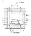
- Fig. 3 is a cross-sectional view schematically illustrating a firing furnace in which the stopping member for a heat insulating layer shown in Figs. 1(a) to 1(c) is used.
- the firing furnace 20 comprises: a muffle 21 formed so as to secure a space for accommodating a molded body to be fired; a heating device 22 disposed over and under the peripheral portion of the muffle 21; a heat insulating layer 23 disposed outside the muffle 21 and the heating device 22; a member 29 for fixing and enclosing a heat insulating layer which is disposed on the peripheral portion of the heat insulating layer 23 and configured to fix the heat insulating layer 23, and further, a furnace wall (not illustrated) comprising metal and the like is formed on the outermost part, which enables isolation from the surrounding atmosphere.
- the heat insulating layer 23 is fixed to the member 29 for fixing and enclosing a heat insulating layer by the stopping member 27 (a bolt 27a and a nut 27b) comprising carbon.
- the furnace wall may be a water-cooling jacket configured so that water may circulate inside the furnace wall.
- the heating device 22 may be provided over and under the muffle 21, or may be provided on the right and left of the muffle 21.
- the entire floor portion of the muffle 21 is supported by a supporting member (not illustrated), and the firing jig 25 inside which a molded body for firing is placed can pass through the muffle 21.
- the heating device 22 comprising graphite and the like is installed around the peripheral portion of the muffle 21, and this heating device 22 is connected to an external power supply (not illustrated) via a terminal.
- the heat insulating layer 23 is formed further outside the heating device 22.
- the stopping member 27 for fixing the heat insulating layer 23 may comprise carbon or a metal on which carbon is coated, it is possible to prevent the reaction of the heat insulating layer 23 and the stopping member 27.
- the heat insulating layer 23 may be layers having carbon as a constituent material, and its constitution is not particularly limited.
- a ceramic molded body comprising porous ceramics is accommodated in the firing jig 25, transported in the firing furnace 20 while placed on the supporting base 26, and fired while allowing the ceramic molded body to pass through the firing furnace 20 at a specific velocity.
- a heating device 22 is provided over and under the muffle 21 at a predetermined interval.
- the firing furnace 20 is configured to gradually raise its temperature, and gradually lower its temperature after reaching the maximum temperature.
- the supporting base 26 on which the firing jig 25 has been placed is continuously transported from the inlet into the firing furnace 20.
- the ceramic molded body is sintered while allowing the supporting base 26 to pass through the firing furnace 20 at a specific velocity, and thereafter the firing jig 25 having a lowered temperature is carried out from the outlet to manufacture a ceramic fired body.
- the stopping member 27 when used in the firing furnace having the above-mentioned structure for a long period of time, since the corrosive gases generated by firing promote a reaction with the stopping member 27 in the portion in the vicinity of the outside of the heat insulating layer in the heat insulating layer, the stopping member 27 may deteriorate mechanically and chemically and break and the like; thus, it is necessary to replace the stopping member 27.
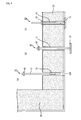
- FIGs. 4(a) to 4(c) are explanatory views each schematically illustrating a way of providing a stopping member 10 for a heat insulating layer in a heat insulating layer 23.
- a nut 15 is first screwed onto the upper end of the stopping member 10 for a heat insulating layer, and a stopper 12 is set so that the stopping member 10 for a heat insulating layer having this nut 15 is substantially linear.
- the stopper 12 is moved so that approximately half of the semi-cylindrical stopper 12 covers a round-pillar shaped shaft rod 11, and the entire stopping member 10 for a heat insulating layer is made substantially linear (see Fig. 4(a) ).
- This substantially linear stopping member 10 for a heat insulating layer is inserted in the through hole 230 for a stopping member formed in the heat insulating layer 23, as illustrated in Fig. 4(a) .
- the remaining part of the stopping member 27 is removed from the heat insulating layer 23 by pushing the end of the stopping member 10 for a heat insulating layer or the stopper 12.
- the shaft rod 11 is moved so that the entire stopper 12 passes through the heat insulating layer 23.
- the stopper 12 is brought into a substantially horizontal state so that the entire stopping member 10 for a heat insulating layer can be in a T shape; and the heat insulating layer 23 can be firmly fixed by the stopping member 10 for a heat insulating layer by screwing a nut 15, and deformation and the like can be prevented in the heat insulating layer 23 upon firing a ceramic molded body.
- a nut 15 is not necessarily screwed on a stopping member 10 for a heat insulating layer from the onset, but the nut 15 may be screwed on the stopping member 10 for a heat insulating layer afterwards (upon being fixed).
- a honeycomb structured body can be obtained by combining a plurality of these ceramic fired bodies with an adhesive and carrying out processing, and the like, thereon.
- the molding process is performed in which a ceramic molded body is manufactured by extrusion molding a wet mixture comprising ceramic powder and a binder.
- silicon carbide powders having different average particle diameters as a ceramic raw material, an organic binder, a plasticizer in liquid form, a lubricant and the like, and water are mixed to prepare a wet mixture for manufacturing a ceramic molded body.
- the wet mixture is loaded into an extrusion molding machine.
- the wet mixture is extrusion-molded into a pillar-shaped ceramic molded body in a predetermined shape having a plurality of cells.
- the ceramic molded body is cut into a predetermined length, and dried by using a drying apparatus, such as a microwave drying apparatus, a hot-air drying apparatus, a dielectric drying apparatus, a reduced-pressure drying apparatus, a vacuum drying apparatus and a freeze drying apparatus, and thereafter, a sealing process is carried out by filling predetermined cells with a plug material paste to be a plug for sealing the cells.
- a drying apparatus such as a microwave drying apparatus, a hot-air drying apparatus, a dielectric drying apparatus, a reduced-pressure drying apparatus, a vacuum drying apparatus and a freeze drying apparatus.
- the degreasing process is performed of heating an organic matter in a ceramic molded body in a degreasing furnace, and decomposing and removing the organic matter.
- the degreased body of the thus obtained ceramic molded body is transported into the above-mentioned firing furnace of the present invention and fired in a non-oxidizing atmosphere to manufacture a ceramic fired body.
- an aggregate with a plurality of ceramic fired bodies being bonded to one another by interposing adhesive layers is formed through a method in which an adhesive paste layer is formed by applying an adhesive paste on side faces of a plurality of ceramic fired bodies and the resulting honeycomb fired bodies are combined sequentially, a method in which each of the honeycomb fired bodies is temporally fixed in a molding frame having substantially the same shape as the shape of the ceramic block to be manufactured and an adhesive paste is injected into each of the gaps between the honeycomb fired bodies, or the like; and if necessary, a side face of the aggregate is processed by using a diamond cutter or the like to form a ceramic block having a round pillar shape, a rectangular pillar shape, or the like. Moreover, a coating process is carried out to form a coat layer on the periphery of the ceramic block formed by applying a sealing material paste to the periphery of the ceramic block, then drying and solidifying the sealing material paste.
- the constituent material of the adhesive paste and that of the sealing material paste it is possible to employ substantially the same material used upon manufacturing a honeycomb molded body. Moreover, the constituent material of the adhesive paste may be the same or different from that of the sealing material paste.
- a round pillar-shaped honeycomb structured body can be manufactured in which a coat layer is formed on the periphery of a ceramic block comprising a plurality of honeycomb fired bodies bonded to one another with an adhesive layer interposed therebetween.
- the coat layer does not necessarily need to be formed, and may be formed on demand.
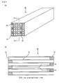
- Fig. 5 is a perspective view schematically illustrating one example of a honeycomb structured body obtained by a method for manufacturing a honeycomb structured body of the present invention.
- Fig. 6(a) is a perspective view schematically illustrating a ceramic fired body used for the honeycomb structured body shown in Fig. 5
- Fig. 6(b) is a B-B line cross-sectional view of Fig. 6(a) .
- a plurality of ceramic fired bodies 40 are combined with one another by interposing adhesive layers 33, and sealing material layers 34 are formed around the periphery of this ceramic block 35.
- a plurality of cells 41 are longitudinally disposed in parallel with one another, and the cell wall 43 that partitions the cells 41 is allowed to function as a particle capturing filter.
- each of the cells 41 formed in the ceramic fired body 40 has either one of the end portions on the inlet side or the outlet side of exhaust gases sealed with the plug 42 as illustrated in Fig. 6(b) so that exhaust gases that have flowed into one of the cells 41 are allowed to flow out of another cell 41 after surely having passed through a cell wall 43 that separates the cells 41.
- exhaust gases pass through the cell wall 43, particulates are captured by the cell wall 43 so that the exhaust gases are purified.
- the stopping member of a heat insulating layer provided in the firing furnace under operation it is possible to repair the stopping member by using the stopping member for a heat insulating layer of the present invention, without disassembling the equipment in the firing furnace such as in a heat insulating layer. That is, it is possible to replace the stopping member of a heat insulating layer and fix the heat insulating layer with another stopping member of the heat insulating layer. For this reason, according to the stopping member for a heat insulating layer of the present invention, a ceramic molded body can be fired efficiently without reducing the production efficiency of the firing furnace.
- the remaining part of the stopping member is removed from the heat insulating layer by pushing the end of the stopping member for a heat insulating layer or the stopper, and it is consequently possible to readily repair the stopping member without disassembling the equipment in the firing furnace.
- the stopping member for a heat insulating layer according to the present invention is used as at least one of the plurality of stopping members. Even in the firing furnace after the repair of replacing the stopping member, the heat insulating layer can be normally fixed by the stopping member, it is possible to fire a ceramic molded body without any difficulty in the same manner as before the repair of the stopping member, and consequently to manufacture a ceramic fired body excellent in quality.
- honeycomb structured bodies were manufactured by the method according to the above-described embodiment and a conventional method, and performance tests were conducted on the obtained honeycomb structured bodies to observe the change of performance of the honeycomb structured bodies.
- a firing furnace illustrated in Fig. 3 was manufactured, and the heat insulating layer 23 was used as a heat insulating layer comprising: an inner layer comprising a carbon member (FR200/OS manufactured by Kureha Corporation, density: 0.16 g/cm 3 , thickness: 100 mm) was used as a heat insulating layer 23; and an outer layer comprising a carbon fiber layer (density: 0.1 g/cm 3 , thickness: 25 mm). And a ceramic fired body was manufactured under the conditions of the maximum temperature of 2200°C inside the muffle in an argon atmosphere at a normal pressure.
- each member that formed a heat insulating layer had an impurity concentration of 0.1% by weight or less
- the stopping member 27 comprising carbon provided in the heat insulating layer 23 also had an impurity concentration of 0.1% by weight or less.
- the raw molded body was dried by using a microwave drying apparatus, a paste having the same composition as that of the raw molded body was filled into a predetermined through hole, and thereafter dried again by using the microwave drying apparatus, and degreased at 400°C.
- the firing furnace was used to perform firing at 2200°C under an argon atmosphere at a normal pressure for 3 hours so as to manufacture a ceramic fired body formed by a silicon carbide sintered body with a size of 34 mm ⁇ 34 mm ⁇ 300 mm, the number of cells of 31 pcs/cm 2 and a thickness of the cell wall of 0.3 mm.
- a ceramic block 35 was formed by combining a plurality of ceramic fired bodies 40 comprising silicon carbide by interposing an adhesive layer 33 as illustrated in Fig. 6 to manufacture a honeycomb structured body 30 in which a sealing material layer 34 was formed on the periphery of this ceramic block 35.
- Example 2 After conducting the processes (1) to (4) in Example 1 and finding that the stopping member was destroyed, the end of the nut 27a that forms the stopping member 27 was cut down instead of replacing the stopping member 27, and formed into a nail shape. Subsequently, the nut 27a was obliquely driven into the heat insulating layer 23 to temporally fix the heat insulating layer 23. Then, the process for manufacturing a ceramic fired body was continuously performed for 2500 hours under the same conditions as in Example 1 to manufacture a ceramic fired body 40. Thereafter, a honeycomb structured body 30 was manufactured in the same manner as in the process (7) in Example 1. After completion of manufacturing the ceramic fired body, deformation was found in the entire heat insulating layer when the heat insulating layer was observed.
- the manufactured honeycomb structured body had larger variations in properties depending on the period of time when the honeycomb structured body was manufactured; and the properties were changed. It seems that the change is attributed to a subtle change of the temperature or the like around the periphery of the molded body that is to be manufactured in a firing furnace.
- Fig. 7 (a) is a front view schematically illustrating the second embodiment of a stopping member for a heat insulating layer according to the present invention
- Fig. 7(b) is a front view schematically illustrating an embodiment in which further modifications have been made on the second embodiment of the stopping member for a heat insulating layer according to the present invention.
- a stopping member 50 for a heat insulating layer according to the present embodiment mainly comprises a shaft rod 51 and stoppers 52 (52a, 52b) provided at the end of the shaft rod 51.
- a stopper supporting member 53 having a cylindrical shape with a bottom is provided and fixed at the end of the shaft rod 51, a through hole 53a for inserting the supporting pin 54 is formed in the vicinity of the bottom of the stopper supporting member 53, and the supporting pin 54 pivotally passes through the through hole 53a.
- the end portions of the semi-cylindrical two stoppers 52a and 52b are pivotally fixed to the supporting pin 54, and the springs 55a and 55b are attached between the stopper supporting member 53 and the stoppers 52a and 52b.
- one long stopper 12 is used in the first embodiment; in contrast, in the second embodiment, a stopper is divided into two parts, and two stoppers 52a and 52b are inwardly folded along the shaft rod 51, thereby allowing the stopping member 50 to be substantially linear (indicated by solid lines). Moreover, since the springs 55a and 55b are attached between the stopper supporting member 53 and the stoppers 52a and 52b, in the case where the force for inwardly folding the stoppers 52a and 52b does not act, the stoppers 52a and 52b extend in a direction substantially perpendicular to the shaft rod 11 (indicated by dashed lines).
- the two stoppers 52a and 52b extend in a direction substantially perpendicular to the shaft rod 11 since the two stoppers 52a and 52b are overlapped with each other in the vicinity of the central part of the stoppers 52a and 52b and do not extend any more, the two stoppers 52a and 52b remain substantially in parallel with each other.
- the stopping member 50 for a heat insulating layer has such a configuration, when it is inserted in the through hole 230 for a stopping member, the force for inwardly folding the two stoppers 52a and 52b acts to make the stopping member 50 substantially linear.
- the force of the springs 55a and 55b causes the stoppers 52a and 52b to extend in a direction substantially perpendicular to the shaft rod 11, that is, in a substantially T shape.
- the shaft rod 51 of the stopping member 50 for a heat insulating layers comprises carbon, screws are threaded at both ends of this shaft rod 51, and the nut 15 (refer to Fig. 4 ) and the stopper supporting member 53 each also comprising carbon can be screwed.
- the stopper 52, the stopper supporting member 53, and the supporting pin 54 are located outside the heat insulating layer 23, and do not directly contact corrosive gases and the like emitted by firing, and can be formed by metals such as SUS, titanium, and aluminum because degradation such as oxidation is less likely to occur.
- this stopping member 50 for a heat insulating layer is the same as that of the first embodiment. As illustrated in Figs. 4 (a) to 4 (c) , after the entire stopping member 50 for a heat insulating layer is made substantially linear, it is inserted in a through hole 230 for a stopping member formed in the heat insulating layer 23. Here, in the case where a part of a damaged stopping member 27 remains inside the through hole 230 for a stopping member, the remaining part of the stopping member 27 is removed from the heat insulating layer 23 by using the stopping member 50 for a heat insulating layer.
- the shaft rod 51 is moved so that the stoppers 52a and 52b may pass through the heat insulating layer 23.
- the stoppers 52a and 52b are expanded to be brought into a substantially horizontal state so that the entire stopping member 50 for a heat insulating layer can be in a T shape as a result of the action of force of springs 55a and 55b; and the heat insulating layer 23 can be firmly fixed by the stopping member 50 for a heat insulating layers by screwing a nut 15.
- a honeycomb structured body can be obtained by combining a plurality of these ceramic fired bodies.
- FIG. 7(b) illustrates an embodiment in which further modifications have been made on the second embodiment of the stopping member for a heat insulating layer according to the present invention. That is, as illustrated in Fig. 7(b) , in the stopping member 60 for a heat insulating layer, metal wires 56a and 56b, instead of the springs 55a and 55b, are attached in the vicinity of both ends of the stoppers 52a and 52b, the wires 56a and 56b passing through the inside of the shaft rod 51 from the upper side thereof.
- the wires 56a and 56b After passing the wires 56a and 56b through a through hole 230 for a stopping member with the stoppers 52a and 52b being inwardly folded (indicated by solid lines), the wires 56a and 56b are pulled, thereby enabling the stoppers 52a and 52b to extend in a direction substantially perpendicular to the shaft rod 51 (in a state indicated by dashed lines), that is, a stopping member for a heat insulating layer in a substantially T shape.
- the two stoppers 52a and 52b extend in a direction substantially perpendicular to the shaft rod 11 since the two stoppers 52a and 52b are overlapped with each other in the vicinity of the central part of the two stoppers 52a and 52b and do not extend any more, the two stoppers 52a and 52b remain substantially in parallel with each other.
- the stopping members 50 and 60 for heat insulating layers illustrated in Figs. 7 (a) and 7 (b) are used as at least one of the plurality of stopping members, the heat insulating layer even after the repair of replacing the stopping member can be normally fixed by the stopping member, it is possible to fire a ceramic molded body without any difficulty in the same manner as before the repair of the stopping member, and consequently to manufacture a ceramic fired body excellent in quality.
- the stopper that configures the stopping member for a heat insulating layer of the present invention is not particularly limited in its shape as long as: it is substantially linear upon passing through a through hole for a stopping member provided in the heat insulating layer; and after an end portion of the stopping member has passed through the through hole for a stopping member, the stopper extends in a direction substantially perpendicular to the shaft rod and functions as a member for fixing the heat insulating layer. Therefore, the stopper may be made of one member in a semi-cylindrical shape as described in the first embodiment, may be made of two members as described in the second embodiment, or may be made of three, four, or more members.
- a stopper having the same configuration as in Figs. 7 (a) and 7 (b) is used, except that, instead of the semi-cylindrical member illustrated in Figs. 7 (a) and 7(b) , there is employed a member having the shape in which a cylinder is divided into four equal parts so as to include the axis of this cylinder.
- the stopper is configured so that: in the case where the stopping members for a heat insulating layer are made substantially linear, these stoppers are inwardly folded so as to enclose the shaft rod; and after passing through an heat insulating layer, the respective stoppers extend in a direction perpendicular to the shaft rod as if an umbrella opened.
- the shaft rod of the stopping member for a heat insulating layer comprises carbon
- the shaft rod of the stopping member for a heat insulating layer may comprise the same material as a material of the ceramic powder mainly contained in the ceramic molded body to be fired.
- the ceramic powder mainly contained in the ceramic molded body to be fired is used to obtain the ceramic fired body.
- the ceramic fired body examples include: nitride ceramics such as aluminium nitride, silicon nitride, boron nitride, and titanium nitride; carbide ceramics such as silicon carbide, zirconium carbide, titanium carbide, tantalum carbide and tungsten carbide; oxide ceramics such as alumina, zirconia, cordierite, mullite and silica; and the like.
- the shaft rod of the stopping member for a heat insulating layer may comprise the same material.
- the stopper comprises metal in the above-mentioned embodiment.
- the stopper may comprise carbon, or ceramics such as the above-mentioned nitride ceramic, carbide ceramic, and oxide ceramic.
- the stopper, the stopper supporting member, and the supporting pin are located outside a heat insulating layer upon fixing the heat insulating layer by using the stopping member for a heat insulating layer, their temperatures decrease, the gases emitted by firing do not reach the outside of the heat insulating layer, and it is possible to fix the heat insulating layer for a long period of time even by using the stopper, the stopper supporting member, and the supporting pin each comprising carbon, metal or ceramic.
- nitride ceramics, carbide ceramics, and the like each having excellent heat resistance have high strength, and can be suitably used as a stopper and the like.
- the fired body obtainable by firing in the firing furnace of the present invention is not particularly limited, and as described above, examples thereof include a nitride ceramic fired body, a carbide ceramic fired body, and the like.
- the firing furnace of the present invention is suitable for manufacturing a non-oxide ceramic member, especially for manufacturing a non-oxide ceramic fired body such as silicon carbide.
- the fired body may comprise silicon-containing ceramics obtainable by blending metallic silicon into silicon carbide, and the ceramics combined with silicon or a silicate compound. Upon adding metallic silicon, it is desirable to add 0 to 45% by weight thereof with respect to the total weight.
- the heat insulating layer used in the firing furnace of the present invention may be one layer or multilayer.
- the layer comprising a carbon fiber layer or a carbon member can be used as the heat insulating layer.
- the carbon fiber layer is sheet-formed or woven by using carbon fibers such as carbon felt and carbon cloth, and carbon fibers may be bonded to one another by an inorganic adhesive, etc.
- the carbon fiber layer preferably has a density of 0.05 to 5 g/cm 3 .
- the carbon fiber layer desirably has a thickness of 1 to 100 mm.
- the material of the layer comprising a carbon member is not particularly limited.
- One such example is a material obtained by compression forming carbon fibers and the like into a plate shape, and its density is preferably 0.1 to 5 g/cm 3 .
- the layer comprising a carbon member desirably has a thickness of 5 to 100 mm. It is desirable to provide a carbon fiber layer on the outermost layer of the heat insulating layer.
- the stopping member for a heat insulating layer of the present invention may be used in combination with the conventionally used stopping member.
- the carbon material that forms the heat insulating layer to be used in the present invention, the carbon material that forms the stopping member for a heat insulating layer used in the present invention, and the carbon material that forms the conventionally used stopping member desirably have a high purity.
- the impurity concentration in a carbon material is desirably 0.1% by weight or less, and more desirably 0.01% by weight or less.
- the firing furnace 10 desirably has an inert gas atmosphere, or an atmosphere of argon, nitrogen, etc.
- the heater used for firing is not limited to a heater that is configured to generate heat by connecting an external power to a carbon member and directly sending current and heat an object to be heated; and the heater may function as a heating device by the induction heating system. That is, the system may be such that: a carbon member serving as both a heating device and muffle is disposed in the vicinity of an object to be heated, for example, a heat insulating layer is disposed immediately outside the carbon member and a coil is provided outside the heat insulating layer; and by applying an alternative current to the coil, an eddy current is generated in the carbon member; thus, the temperature of the carbon member is raised to heat an object to be heated.
- a plurality of honeycomb molded bodies may be accommodated in the above-mentioned firing jig, and the firing jigs may be laminated in a plurality of stages of firing jigs.
- the shape of the honeycomb structured body of the present invention obtained by the above-described method is not particularly limited to a round pillar shape, and may have a pillar shape or a rectangular pillar shape having a flat shape such a cylindroid shape on its cross section.
- the honeycomb structured body of the present invention obtained by the above-described method, an end portion of each of the cells is not necessarily sealed.
- the honeycomb structured body can be used as a catalyst supporting carrier capable of supporting the catalyst for converting exhaust gases for converting the toxic components, such as HC, CO, and NOx in exhaust gases.
- the catalyst for converting exhaust gases is not particularly limited, and examples thereof include noble metals such as platinum, palladium, and rhodium. These noble metals may be used independently, or two or more of these may be used in combination.
Landscapes
- Engineering & Computer Science (AREA)
- Chemical & Material Sciences (AREA)
- Ceramic Engineering (AREA)
- Mechanical Engineering (AREA)
- General Engineering & Computer Science (AREA)
- Tunnel Furnaces (AREA)
- Furnace Housings, Linings, Walls, And Ceilings (AREA)
- Muffle Furnaces And Rotary Kilns (AREA)
Abstract
It is an object of the present invention to provide a stopping member (10) for a heat insulating layer having a new structure of a stopping member (10) for fixing a heat insulating layer which is easily replaceable in a short period of time even in the case where inconveniences, such as breaks, arise in the stopping member (10) for fixing a heat insulating layer. A stopping member (10) for a heat insulating layer according to the present invention is configured to fix a heat insulating layer in a firing furnace, the firing furnace comprising: a muffle formed so as to secure a space for accommodating a ceramic molded body; a heater disposed outside the muffle; and the heat insulating layer provided so as to enclose the muffle and the heater, the stopping member (10) comprising: a shaft rod (11); and a stopper (12) provided on an end of the shaft rod (11), wherein the stopping member (10) is substantially linear upon passing through a through hole for a stopping member (10) provided in the heat insulating layer, and after an end portion of the stopping member (10) has passed through the through hole for a stopping member (10), the stopper (12) extends in a direction substantially perpendicular to the shaft rod (11), and functions as a member for fixing the heat insulating layer.
Description
- The present invention relates to a stopping member for a heat insulating layer, a firing furnace, and a method for manufacturing a honeycomb structured body using the firing furnace.
- There have been proposed various honeycomb filters for purifying and/or converting exhaust gases and various catalyst supporting carriers, which are configured to purify and/or convert exhaust gases discharged from internal combustions of vehicles such as buses and trucks, construction machines, and the like.
- A honeycomb structured body comprising a porous body made of non-oxide ceramic such as silicon carbide having excellent heat resistance, is used as such a honeycomb filter for purifying exhaust gases and the like.
- As conventional examples,
Patent Document 1 and Patent Document 2 disclose a firing furnace for manufacturing this kind of non-oxide ceramic member.
As disclosed inPatent Document 1, the firing furnace for manufacturing such a non-oxide ceramic member comprises: a muffle, a heating device, and the like in the firing furnace; and a heat insulating layer provided so as to enclose the muffle and the heating device thereinside. - The heat insulating layer is fixed by a stopping member in a firing furnace of this kind. Used for this stopping member are: the bolt and nut comprising carbon excellent in heat resistance, as disclosed in
Patent Document 1 or Patent Document 2; or the bolt and nut disclosed in Patent Document 3. - However, when the firing furnace having the structure comprising the above-mentioned stopping member is used for a long period of time, since oxidation reaction of the stopping member proceeds because of gases and the like that have been emitted by the reaction upon firing a non-oxide ceramic member in the portion near the outside of the heat insulating layer in the heat insulating layer, the stopping member may deteriorate mechanically and chemically and break and the like. Then, since these breaks and the like make it impossible to fix a heat insulating material, problematically, the heat deformation and the like of the heat insulating layer occur, significantly lower the heat insulating property, and consequently vary the quality of the fired products.
- When a stopping member breaks as thus described, it is desirable to replace the stopping member. In contrast, when the stopping member is made of a bolt and a nut, it is necessary to insert the bolt in a through hole for inserting a bolt in a heat insulating material, thereafter screw the nut from the inside and outside of the heat insulating material, and tighten the heat insulating material by rotating this nut.
- However, regarding the firing furnace in which the heat insulating layer and the like have been installed, it is often difficult to screw a nut from the outside of a heat insulating layer unless the heat insulating layer and its peripheral equipment are removed. Since it is impossible to use a firing furnace for a long period of time when the removal task of the heat insulating layer and the like is once performed, production efficiency thereof is problematically lowered. Especially the removal of the heat insulating layer at the lower side of the firing furnace is an extremely difficult task.
-
- Patent Document 1:
WO 2006/016430 A1 - Patent Document 2:
JP-A 63-302292 - Patent Document 3:
JP-U 60-99352 JP-U 62-8409 - The present invention aims to solve these problems, and it is an object of the present invention to provide: a stopping member for a heat insulating layer having a new structure of a stopping member for fixing a heat insulating layer which is easily replaceable in a short period of time even in the case where inconveniences, such as breaks, arise in the stopping member for fixing a heat insulating layer; a firing furnace using the stopping member for an insulating member; and a method for manufacturing a honeycomb structured body using the firing furnace.
- That is, a stopping member for a heat insulating layer according to claim 1 configured to fix a heat insulating layer in a firing furnace, the firing furnace comprising: a muffle formed so as to secure a space for accommodating a ceramic molded body; a heater disposed outside the muffle; and the heat insulating layer provided so as to enclose the muffle and the heater, the stopping member comprising: a shaft rod; and a stopper provided on an end of the shaft rod, wherein the stopping member is substantially linear upon passing through a through hole for a stopping member provided in the heat insulating layer, and after an end portion of the stopping member has passed through the through hole for a stopping member, the stopper extends in a direction substantially perpendicular to the shaft rod, and functions as a member for fixing the heat insulating layer.
- The stopping member for a heat insulating layer according to
claim 1 is substantially linear upon passing through a through hole for a stopping member provided in a heat insulating layer. After an end portion of the stopping member has passed through the heat insulating layer, the stopper operates and extends in a direction substantially perpendicular to the shaft rod, and functions as a member for fixing the heat insulating layer.
Therefore, when an inconvenience occurs in the stopping member in the heat insulating layer provided in the firing furnace under operation, it is possible to repair the stopping member by using the stopping member for a heat insulating layer of the present invention, without disassembling the equipment in the firing furnace such as in a heat insulating layer. That is, it is possible to replace the stopping member in the heat insulating layer and fix the heat insulating layer with another stopping member of a heat insulating layer. For this reason, according to the stopping member for a heat insulating layer in accordance withclaim 1, a ceramic molded body can be fired efficiently without reducing the production efficiency of the firing furnace. - In addition, when a part of a damaged stopping member remains inside the through hole for a stopping member, the remaining part of the stopping member can be removed from the heat insulating layer by pushing an end portion of the stopping member for a heat insulating layer or a stopper, and it is consequently possible to readily replace the stopping member without disassembling the equipment in the firing furnace.
- In the stopping member for a heat insulating layer according to claim 2, the stopper that configures the stopping member is semi-cylindrical, and a central part of the stopper is pivotally supported on the end of the shaft rod.
- Since the stopper according to claim 2 that configures the stopping member is semi-cylindrical, and a central part of the stopper is pivotally supported on the end of the shaft rod, when the stopping member for a heat insulating layer passes through the through hole for a stopping member provided in the heat insulating layer, by rotating the stopper so as to be in parallel with the shaft rod, it is possible to make a configuration, as illustrated in
Fig. 1(c) , in which a portion of the stopper covers the shaft rod and the shaft rod and the portion of the stopper are integrated. Thereby, the stopping member for a heat insulating layer can be substantially linear. Therefore, the stopping member for a heat insulating layer can easily pass through the through hole for a stopping member by adopting the above-mentioned configuration. On the other hand, after the stopping member for a heat insulating layer passing therethrough, by utilizing the weight of the stopper and the like to make the stopper substantially perpendicular to the shaft rod (in a T shape), attaching a nut to an end portion opposite to an end portion on which the stopper is provided, and fastening the nut, it is possible to tightly fix the stopping member for a heat insulating layer to the heat insulating layer. This enables a rapid repair of the heat insulating layer (replacement of the stopping member). - The stopping member for a heat insulating layer according to claim 3 is the stopping member for a heat insulating layer according to claim 1 or 2, wherein the shaft rod of the stopping member comprises carbon.
- In the stopping member for a heat insulating layer according to claim 3, since the shaft rod of the stopping member comprises carbon, the stopping member for a heat insulating layer has heat resistance and can maintain mechanical strength even at a high temperature, and the reaction of the stopping member for a heat insulating layer and gases in the firing furnace does not proceed, leading to excellent durability.
- The stopping member for a heat insulating layer according to claim 4 is the stopping member for a heat insulating layer according to claim 1 or 2, wherein the shaft rod of the stopping member comprises the same material as a material of ceramic powder contained in the ceramic molded body.
- In the stopping member for a heat insulating layer according to claim 4, since the shaft rod of the stopping member comprises the same material as a material of ceramic powder contained in the ceramic molded body, there is no possibility that other impurities may mix in the ceramic molded body upon firing a ceramic molded body, and it is possible to manufacture a ceramic fired body excellent in quality. Moreover, the reaction of the stopping member for a heat insulating layer and gases in the firing furnace does not proceed, resulting in excellent durability.
- The stopping member for a heat insulating layer according to claim 5 is the stopping member for a heat insulating layer according to any of
claims 1 to 4, wherein the stopper of the stopping member comprise carbon, metal, or ceramic. - In the stopping member for a heat insulating layer according to claim 5, when a heat insulating layer is fixed using the stopping member for a heat insulating layer, since the stopper is located outside the heat insulating layer, the stopper has a low temperature, the gases generated by firing are less likely to reach the outside of the heat insulating layer. Even when the end portion of the stopper comprises carbon, metal, or ceramic, the stopper is less susceptible to gases generated by firing, and it is consequently possible to fix the heat insulating layer for a long period of time.
- A firing furnace according to claim 6 comprises: a muffle formed so as to secure a space for accommodating a ceramic molded body; a heater disposed outside the muffle; a heat insulating layer provided so as to enclose the muffle and the heater; and a plurality of stopping members for heat insulating layers configured to fix the heat insulating layer, wherein a stopping member for a heat insulating layer according to any of
claims 1 to 5 is used as at least one of the plurality of stopping members. - In the firing furnace according to claim 6, since the stopping member for a heat insulating layer according to any of
claims 1 to 5 is used as at least one of the plurality of stopping members. Even in the firing furnace after the repair of replacing the stopping member, the heat insulating layer can be normally fixed by the stopping member, it is possible to fire a ceramic molded body without any difficulty in the same manner as before the repair, and consequently to manufacture a ceramic fired body excellent in quality. - In the firing furnace according to
claim 7, in addition to the characteristics of claim 6, the heat insulating layer comprises a plurality of heat insulating layers, and an outermost layer of the plurality of heat insulating layers comprises a carbon fiber layer. - In the firing furnace according to
claim 7, since the outermost layer of the plurality of heat insulating layers comprises a carbon fiber layer excellent in heat insulating property, the heat insulating layer has excellent heat insulating property, and it is possible to fire a ceramic molded body efficiently. - A method for manufacturing a honeycomb structured body according to claim 8 comprises the steps of: manufacturing a ceramic molded body; and transporting the manufactured ceramic molded body into a firing furnace according to
claim 6 or 7, and firing the ceramic molded body to manufacture a ceramic fired body. - In the method for manufacturing a honeycomb structured body according to claim 8, since the firing furnace of the present invention is used, it is possible to fire a ceramic molded body without any difficulty in the same manner as before the repair even after the repair of replacing the stopping member, to manufacture a ceramic fired body excellent in quality, and consequently to manufacture a honeycomb structured body having less variations in characteristics by using one or a plurality of the ceramic fired bodies.
- The method for manufacturing a honeycomb structured body according to claim 9 is the method for manufacturing a honeycomb structured body according to claim 8, wherein the ceramic fired body comprises a silicon carbide material.
- In the method for manufacturing a honeycomb structured body according to claim 9, since the ceramic fired body comprises a silicon carbide material, it is possible to manufacture a honeycomb structured body excellent in heat resistance and mechanical property.
- The above, and the other objects, features and advantages of the present invention will be made apparent from the description of preferred embodiments, given as non-limiting examples, with reference to the accompanying drawings in which:
-
Fig. 1(a) is a top view schematically illustrating one embodiment of a stopping member for a heat insulating layer according to the present invention; -
Fig. 1(b) is a front view of the stopping member; -
Fig. 1(c) is a side view of the stopping member; -
Fig. 2 is a partially enlarged side view schematically illustrating a portion of the stopping member for a heat insulating layer shown inFig. 1(c) , on which a stopper is pivotally supported; -
Fig. 3 is a cross-sectional view schematically illustrating a firing furnace in which the stopping member for a heat insulating layer according to the present invention shown inFigs. 1(a) to 1(c) is used; -
Figs. 4(a) to 4(c) are explanatory views each schematically illustrating a way of providing a stoppingmember 10 for a heat insulating layer in aheat insulating layer 23; -
Fig. 5 is a perspective view schematically illustrating one example of a honeycomb structured body obtained by a method for manufacturing a honeycomb structured body of the present invention; -
Fig. 6(a) is a perspective view schematically illustrating a ceramic fired body used for the honeycomb structured body shown inFig. 5 ; -
Fig. 6 (b) is a B-B line cross-sectional view ofFig. 6(a) ; -
Fig. 7 (a) is a front view schematically illustrating the second embodiment of a stopping member for a heat insulating layer according to the present invention; and -
Fig. 7 (b) is a front view schematically illustrating an embodiment that further modifies the second embodiment of the stopping member for a heat insulating layer according to the present invention, wherein:- 10, 50, 60... Stopping member for heat insulating layer; 11, 51... Shaft rod; 12, 52... Stopper; 52a, 52b... Stopper; 13, 53... Stopper supporting member; 13a, 53a... Through hole; 14, 54... Supporting pin; 15... Nut; 20... Firing furnace; 21... Muffle; 22... Heating device; 23... Heat insulating layer; 25... Firing jig; 26... Supporting base; 230... Through hole for stopping member; 27... Stopping member; 27a... Bolt; 27b... Nut; 29... Member for fixing and enclosing heat insulating layer; 30... Honeycomb structured body; 33... Adhesive layer; 34... Sealing material layer; 35... Ceramic block; 40... Honeycomb fired body; 41... Cell; 42... Plug; 43... Cell wall; 55a, 55b... Spring; and 56a, 56b... Wire.
- Referring to the drawings, the following will describe a first embodiment, one embodiment of a stopping member for a heat insulating layer, a firing furnace comprising the stopping member for a heat insulating layer, and a method for manufacturing a honeycomb structured body using the firing furnace, according to the present invention.
-
-
Fig. 1(a) is a top view schematically illustrating one embodiment of a stopping member for a heat insulating layer according to the present invention,Fig. 1(b) is a front view of the stopping member, andFig. 1(c) is a side view of the stopping member. -
Fig. 2 is a partially enlarged side view schematically illustrating a portion (A) of the stopping member for a heat insulating layer shown inFig. 1(c) , on which a stopper is pivotally supported. - As illustrated in
Fig. 1 , a stoppingmember 10 for a heat insulating layer according to the present embodiment mainly comprises ashaft rod 11 and astopper 12 provided on the end of theshaft rod 11. More specifically, as illustrated inFig. 2 , thestopper supporting member 13 having a cylindrical shape with a bottom is provided and fixed at the end of theshaft rod 11, a throughhole 13a for passing the supportingpin 14 therethrough in the vicinity of the bottom of thestopper supporting member 13 is formed, and the supportingpin 14 pivotally passes through the throughhole 13a. Moreover, the inner part of thesemi-cylindrical stopper 12 is fixed to both ends of the supportingpin 14 by a method such as welding. The position where the supportingpin 14 is fixed is the central part of thestopper 12, and therefore, thestopper 12 including the supportingpin 14 is pivotally supported in a through hole portion of thestopper supporting member 13 fixed to theshaft rod 11. - Since the stopping
member 10 for a heat insulating layer has such a structure, as illustrated inFig. 1(b) , thestopper 12 is pivotable around the pivotally supported portion. Thestopper 12 may extend in a direction perpendicular to a longitudinal direction of theshaft rod 11, that is, in a substantially T shape; alternatively, thestopper 12 may be in parallel with the longitudinal direction of theshaft rod 11, that is, in a substantially linear shape. - The
shaft rod 11 of the stoppingmember 10 for a heat insulating layer comprises carbon, both ends of thisshaft rod 11 are threaded, and it is possible to thread a nut 15 (seeFig. 4 ) comprising carbon, and also to thread astopper supporting member 13 comprising metal. - Moreover, the
stopper 12, thestopper supporting member 13, and the supportingpin 14 are located outside theheat insulating layer 23 upon being attached to theheat insulating layer 23, do not directly contact corrosive gases generated by firing and the like and are less susceptible to degradation such as oxidation, and may comprise metals such as SUS, titanium, and aluminium. -
Fig. 3 is a cross-sectional view schematically illustrating a firing furnace in which the stopping member for a heat insulating layer shown inFigs. 1(a) to 1(c) is used.
The firingfurnace 20 comprises: a muffle 21 formed so as to secure a space for accommodating a molded body to be fired; aheating device 22 disposed over and under the peripheral portion of themuffle 21; aheat insulating layer 23 disposed outside themuffle 21 and theheating device 22; amember 29 for fixing and enclosing a heat insulating layer which is disposed on the peripheral portion of theheat insulating layer 23 and configured to fix theheat insulating layer 23, and further, a furnace wall (not illustrated) comprising metal and the like is formed on the outermost part, which enables isolation from the surrounding atmosphere. Here, theheat insulating layer 23 is fixed to themember 29 for fixing and enclosing a heat insulating layer by the stopping member 27 (abolt 27a and anut 27b) comprising carbon.
The furnace wall may be a water-cooling jacket configured so that water may circulate inside the furnace wall. Theheating device 22 may be provided over and under themuffle 21, or may be provided on the right and left of themuffle 21. - The entire floor portion of the
muffle 21 is supported by a supporting member (not illustrated), and the firingjig 25 inside which a molded body for firing is placed can pass through themuffle 21. Theheating device 22 comprising graphite and the like is installed around the peripheral portion of themuffle 21, and thisheating device 22 is connected to an external power supply (not illustrated) via a terminal. In addition, theheat insulating layer 23 is formed further outside theheating device 22. - In this firing
furnace 20, since the stoppingmember 27 for fixing theheat insulating layer 23 may comprise carbon or a metal on which carbon is coated, it is possible to prevent the reaction of theheat insulating layer 23 and the stoppingmember 27. Here, theheat insulating layer 23 may be layers having carbon as a constituent material, and its constitution is not particularly limited. - As illustrated in
Fig. 3 , upon firing in the firingfurnace 20 having such a constitution, a ceramic molded body comprising porous ceramics is accommodated in the firingjig 25, transported in the firingfurnace 20 while placed on the supportingbase 26, and fired while allowing the ceramic molded body to pass through the firingfurnace 20 at a specific velocity. - In the firing
furnace 20, aheating device 22 is provided over and under themuffle 21 at a predetermined interval. In the process where the firingjig 25 passes through the firingfurnace 25, with the heat of thisheating device 22, the firingfurnace 20 is configured to gradually raise its temperature, and gradually lower its temperature after reaching the maximum temperature. The supportingbase 26 on which the firingjig 25 has been placed is continuously transported from the inlet into the firingfurnace 20. The ceramic molded body is sintered while allowing the supportingbase 26 to pass through the firingfurnace 20 at a specific velocity, and thereafter the firingjig 25 having a lowered temperature is carried out from the outlet to manufacture a ceramic fired body. - However, when the stopping
member 27 is used in the firing furnace having the above-mentioned structure for a long period of time, since the corrosive gases generated by firing promote a reaction with the stoppingmember 27 in the portion in the vicinity of the outside of the heat insulating layer in the heat insulating layer, the stoppingmember 27 may deteriorate mechanically and chemically and break and the like; thus, it is necessary to replace the stoppingmember 27. - However, it is often difficult to screw a
nut 27b onto abolt 27a from the outside of aheat insulating layer 23 unless theheat insulating layer 23 and its peripheral equipment are removed in the firingfurnace 20 as illustrated inFig. 3 . Since it is impossible to use a firing furnace for a long period of time when the removal task of the heat insulating layer and the like is once performed, production efficiency thereof is problematically lowered. Especially the removal of theheat insulating layer 23 at the lower side of the firing furnace is an extremely difficult task. - In the present invention, it is possible to replace a stopping member easily and quickly by using the stopping
member 10 for a heat insulating layer according to the present invention.
Figs. 4(a) to 4(c) are explanatory views each schematically illustrating a way of providing a stoppingmember 10 for a heat insulating layer in aheat insulating layer 23.
Upon providing the stoppingmember 10 for a heat insulating layer in theheat insulating layer 23, anut 15 is first screwed onto the upper end of the stoppingmember 10 for a heat insulating layer, and astopper 12 is set so that the stoppingmember 10 for a heat insulating layer having thisnut 15 is substantially linear. That is, thestopper 12 is moved so that approximately half of thesemi-cylindrical stopper 12 covers a round-pillar shapedshaft rod 11, and the entire stoppingmember 10 for a heat insulating layer is made substantially linear (seeFig. 4(a) ). - This substantially linear stopping
member 10 for a heat insulating layer is inserted in the throughhole 230 for a stopping member formed in theheat insulating layer 23, as illustrated inFig. 4(a) . Here, in the case where a part of a damaged stoppingmember 27 remains inside the throughhole 230 for a stopping member at this time, the remaining part of the stoppingmember 27 is removed from theheat insulating layer 23 by pushing the end of the stoppingmember 10 for a heat insulating layer or thestopper 12. - Next, as illustrated in
Fig. 4(b) , theshaft rod 11 is moved so that theentire stopper 12 passes through theheat insulating layer 23. Then, as illustrated inFig. 4(c) , thestopper 12 is brought into a substantially horizontal state so that the entire stoppingmember 10 for a heat insulating layer can be in a T shape; and theheat insulating layer 23 can be firmly fixed by the stoppingmember 10 for a heat insulating layer by screwing anut 15, and deformation and the like can be prevented in theheat insulating layer 23 upon firing a ceramic molded body. In the method for disposing a stoppingmember 10 for a heat insulating layer illustrated inFigs. 4(a) to 4(c) , anut 15 is not necessarily screwed on a stoppingmember 10 for a heat insulating layer from the onset, but thenut 15 may be screwed on the stoppingmember 10 for a heat insulating layer afterwards (upon being fixed). - Thus, by using a firing furnace having the stopping
member 10 for a heat insulating layer of the present invention, it is possible to fire a ceramic molded body in the same manner as before the repair of the stopping member, thereby obtaining a ceramic fired body. A honeycomb structured body can be obtained by combining a plurality of these ceramic fired bodies with an adhesive and carrying out processing, and the like, thereon. - Next, a method for manufacturing the above-mentioned honeycomb structured body will be described.
The molding process is performed in which a ceramic molded body is manufactured by extrusion molding a wet mixture comprising ceramic powder and a binder. - First, silicon carbide powders having different average particle diameters as a ceramic raw material, an organic binder, a plasticizer in liquid form, a lubricant and the like, and water are mixed to prepare a wet mixture for manufacturing a ceramic molded body.
- Subsequently, the wet mixture is loaded into an extrusion molding machine.
When the wet mixture is loaded into the extrusion molding machine, the wet mixture is extrusion-molded into a pillar-shaped ceramic molded body in a predetermined shape having a plurality of cells. - Next, the ceramic molded body is cut into a predetermined length, and dried by using a drying apparatus, such as a microwave drying apparatus, a hot-air drying apparatus, a dielectric drying apparatus, a reduced-pressure drying apparatus, a vacuum drying apparatus and a freeze drying apparatus, and thereafter, a sealing process is carried out by filling predetermined cells with a plug material paste to be a plug for sealing the cells.
Here, conditions conventionally used upon manufacturing a ceramic fired body are applicable for carrying out the cutting process, the drying process and the sealing process. - Subsequently, the degreasing process is performed of heating an organic matter in a ceramic molded body in a degreasing furnace, and decomposing and removing the organic matter.
The degreased body of the thus obtained ceramic molded body is transported into the above-mentioned firing furnace of the present invention and fired in a non-oxidizing atmosphere to manufacture a ceramic fired body. - Thereafter, an aggregate with a plurality of ceramic fired bodies being bonded to one another by interposing adhesive layers is formed through a method in which an adhesive paste layer is formed by applying an adhesive paste on side faces of a plurality of ceramic fired bodies and the resulting honeycomb fired bodies are combined sequentially, a method in which each of the honeycomb fired bodies is temporally fixed in a molding frame having substantially the same shape as the shape of the ceramic block to be manufactured and an adhesive paste is injected into each of the gaps between the honeycomb fired bodies, or the like; and if necessary, a side face of the aggregate is processed by using a diamond cutter or the like to form a ceramic block having a round pillar shape, a rectangular pillar shape, or the like.
Moreover, a coating process is carried out to form a coat layer on the periphery of the ceramic block formed by applying a sealing material paste to the periphery of the ceramic block, then drying and solidifying the sealing material paste. - As a constituent material of the adhesive paste and that of the sealing material paste, it is possible to employ substantially the same material used upon manufacturing a honeycomb molded body. Moreover, the constituent material of the adhesive paste may be the same or different from that of the sealing material paste.
- Through the above-mentioned processes, a round pillar-shaped honeycomb structured body can be manufactured in which a coat layer is formed on the periphery of a ceramic block comprising a plurality of honeycomb fired bodies bonded to one another with an adhesive layer interposed therebetween.
Here, the coat layer does not necessarily need to be formed, and may be formed on demand. -
Fig. 5 is a perspective view schematically illustrating one example of a honeycomb structured body obtained by a method for manufacturing a honeycomb structured body of the present invention.
Fig. 6(a) is a perspective view schematically illustrating a ceramic fired body used for the honeycomb structured body shown inFig. 5 , andFig. 6(b) is a B-B line cross-sectional view ofFig. 6(a) .
In this honeycomb structuredbody 30, a plurality of ceramic firedbodies 40 are combined with one another by interposingadhesive layers 33, and sealingmaterial layers 34 are formed around the periphery of thisceramic block 35. Moreover, in this ceramic firedbody 40, a plurality ofcells 41 are longitudinally disposed in parallel with one another, and thecell wall 43 that partitions thecells 41 is allowed to function as a particle capturing filter. - In other words, each of the
cells 41 formed in the ceramic firedbody 40 has either one of the end portions on the inlet side or the outlet side of exhaust gases sealed with theplug 42 as illustrated inFig. 6(b) so that exhaust gases that have flowed into one of thecells 41 are allowed to flow out of anothercell 41 after surely having passed through acell wall 43 that separates thecells 41. When exhaust gases pass through thecell wall 43, particulates are captured by thecell wall 43 so that the exhaust gases are purified. - The actions and effects of a stopping member for a heat insulating layer, a firing furnace provided with the stopping member for a heat insulating layer, and a method for manufacturing a honeycomb structured body using the firing furnace, according to the first embodiment, will be described.
- (1) The stopping member for a heat insulating layer according to the present embodiment is substantially linear upon passing through a through hole for a stopping member provided in the heat insulating layer. After an end portion of the stopping member has passed through the heat insulating layer, the operation of the stopper forms the stopping member for a heat insulating layer into a T shape, and screwing a nut on the stopper enables the stopper to function as a member for fixing the heat insulating layer.
- Therefore, when an inconvenience occurs in the stopping member of a heat insulating layer provided in the firing furnace under operation, it is possible to repair the stopping member by using the stopping member for a heat insulating layer of the present invention, without disassembling the equipment in the firing furnace such as in a heat insulating layer. That is, it is possible to replace the stopping member of a heat insulating layer and fix the heat insulating layer with another stopping member of the heat insulating layer. For this reason, according to the stopping member for a heat insulating layer of the present invention, a ceramic molded body can be fired efficiently without reducing the production efficiency of the firing furnace.
- In addition, even if a part of a damaged stopping member remains inside the through hole for a stopping member, the remaining part of the stopping member is removed from the heat insulating layer by pushing the end of the stopping member for a heat insulating layer or the stopper, and it is consequently possible to readily repair the stopping member without disassembling the equipment in the firing furnace.
- In the firing furnace according to the present embodiment, since the stopping member for a heat insulating layer according to the present invention is used as at least one of the plurality of stopping members. Even in the firing furnace after the repair of replacing the stopping member, the heat insulating layer can be normally fixed by the stopping member, it is possible to fire a ceramic molded body without any difficulty in the same manner as before the repair of the stopping member, and consequently to manufacture a ceramic fired body excellent in quality.
- (3) In the method for manufacturing a honeycomb structured body according to the present embodiment, since the firing furnace of the present invention is used, it is possible to fire a ceramic molded body without any difficulty in the same manner as before the repair even after the repair of replacing the stopping member by the stopping member for a heat insulating layer of the present invention, to manufacture a ceramic fired body excellent in quality, and consequently to obtain a honeycomb structured body excellent in its performance by using the ceramic fired body.
- The following will describe Examples that more specifically disclose a first embodiment of the present invention, and the present invention should not be intended to be limited only to these Examples.
- In the following Examples and Comparative Examples, honeycomb structured bodies were manufactured by the method according to the above-described embodiment and a conventional method, and performance tests were conducted on the obtained honeycomb structured bodies to observe the change of performance of the honeycomb structured bodies.
- (1) A firing furnace illustrated in
Fig. 3 was manufactured, and theheat insulating layer 23 was used as a heat insulating layer comprising: an inner layer comprising a carbon member (FR200/OS manufactured by Kureha Corporation, density: 0.16 g/cm3, thickness: 100 mm) was used as aheat insulating layer 23; and an outer layer comprising a carbon fiber layer (density: 0.1 g/cm3, thickness: 25 mm). And a ceramic fired body was manufactured under the conditions of the maximum temperature of 2200°C inside the muffle in an argon atmosphere at a normal pressure.
Here, each member that formed a heat insulating layer had an impurity concentration of 0.1% by weight or less, the stoppingmember 27 comprising carbon provided in theheat insulating layer 23 also had an impurity concentration of 0.1% by weight or less. - (2) In other words, 60% by weight of α-type silicon carbide powder having an average particle diameter of 10 µm and 40% by weight of α-type silicon carbide powder having an average particle diameter of 0.5 µm were wet-mixed. To 100 parts by weight of the resulting mixture, 5 parts by weight of an organic binder (methylcellulose) and 10 parts by weight of water were added and kneaded. Thereafter, a small amount of a plasticizer and a lubricant were added and further kneaded to prepare a wet mixture, and extrusion-molded to manufacture a raw molded body.
- (3) Next, the raw molded body was dried by using a microwave drying apparatus, a paste having the same composition as that of the raw molded body was filled into a predetermined through hole, and thereafter dried again by using the microwave drying apparatus, and degreased at 400°C. The firing furnace was used to perform firing at 2200°C under an argon atmosphere at a normal pressure for 3 hours so as to manufacture a ceramic fired body formed by a silicon carbide sintered body with a size of 34 mm × 34 mm × 300 mm, the number of cells of 31 pcs/cm2 and a thickness of the cell wall of 0.3 mm.
- (4) When the process for manufacturing the ceramic fired body using this firing
furnace 20 was performed continuously for 2500 hours, the three stoppingmembers 27 comprising the stoppingmember 27 disposed at the lower side of the firing furnace was oxidized, thebolt 27a of the stoppingmember 27 at the lower side was particularly damaged and cut into two. Then, a part of thebolt 27a located inside and thenut 27b were successfully pulled out from the inside; on the other hand, a part of thebolt 27b located outside and thenut 27b were still located inside theheat insulating layer 23. - (5) By using the stopping
member 10 for a heat insulating layer illustrated inFig. 1 , the part of thebolt 27b located outside and thenut 27b were removed theheat insulating layer 23 by pushing the end portion including thestopper 12, and these were completely removed. Then, theheat insulating layer 23 was firmly fixed to amember 29 for fixing and enclosing a heat insulating layer using this stoppingmember 10 for a heat insulating layer. - (6) Thereafter, by using the firing furnace provided with three stopping
members 10 for heat insulating layers as thus provided, the process of manufacturing a ceramic fired body was performed continuously for 2000 hours to manufacture a ceramic firedbody 40. - (7) After this, by using the above-mentioned method, a
ceramic block 35 was formed by combining a plurality of ceramic firedbodies 40 comprising silicon carbide by interposing anadhesive layer 33 as illustrated inFig. 6 to manufacture a honeycomb structuredbody 30 in which a sealingmaterial layer 34 was formed on the periphery of thisceramic block 35.
The obtained honeycomb structuredbodies 30, when manufactured at any time point, had the designed properties. - After conducting the processes (1) to (4) in Example 1 and finding that the stopping member was destroyed, the end of the
nut 27a that forms the stoppingmember 27 was cut down instead of replacing the stoppingmember 27, and formed into a nail shape. Subsequently, thenut 27a was obliquely driven into theheat insulating layer 23 to temporally fix theheat insulating layer 23. Then, the process for manufacturing a ceramic fired body was continuously performed for 2500 hours under the same conditions as in Example 1 to manufacture a ceramic firedbody 40.
Thereafter, a honeycomb structuredbody 30 was manufactured in the same manner as in the process (7) in Example 1. After completion of manufacturing the ceramic fired body, deformation was found in the entire heat insulating layer when the heat insulating layer was observed.
Here, the manufactured honeycomb structured body had larger variations in properties depending on the period of time when the honeycomb structured body was manufactured; and the properties were changed. It seems that the change is attributed to a subtle change of the temperature or the like around the periphery of the molded body that is to be manufactured in a firing furnace. -
Fig. 7 (a) is a front view schematically illustrating the second embodiment of a stopping member for a heat insulating layer according to the present invention, andFig. 7(b) is a front view schematically illustrating an embodiment in which further modifications have been made on the second embodiment of the stopping member for a heat insulating layer according to the present invention.
As illustrated inFig. 7(a) , a stoppingmember 50 for a heat insulating layer according to the present embodiment mainly comprises ashaft rod 51 and stoppers 52 (52a, 52b) provided at the end of theshaft rod 51. More specifically, astopper supporting member 53 having a cylindrical shape with a bottom is provided and fixed at the end of theshaft rod 51, a throughhole 53a for inserting the supportingpin 54 is formed in the vicinity of the bottom of thestopper supporting member 53, and the supportingpin 54 pivotally passes through the throughhole 53a. Moreover, the end portions of the semi-cylindrical twostoppers pin 54, and thesprings stopper supporting member 53 and thestoppers - That is, one
long stopper 12 is used in the first embodiment; in contrast, in the second embodiment, a stopper is divided into two parts, and twostoppers shaft rod 51, thereby allowing the stoppingmember 50 to be substantially linear (indicated by solid lines). Moreover, since thesprings stopper supporting member 53 and thestoppers stoppers stoppers stoppers shaft rod 11, since the twostoppers stoppers stoppers - Since the stopping
member 50 for a heat insulating layer has such a configuration, when it is inserted in the throughhole 230 for a stopping member, the force for inwardly folding the twostoppers member 50 substantially linear. When the twostoppers hole 230 for a stopping member, the force of thesprings stoppers shaft rod 11, that is, in a substantially T shape. - The
shaft rod 51 of the stoppingmember 50 for a heat insulating layers comprises carbon, screws are threaded at both ends of thisshaft rod 51, and the nut 15 (refer toFig. 4 ) and thestopper supporting member 53 each also comprising carbon can be screwed. - When attached to the
heat insulating layer 23, thestopper 52, thestopper supporting member 53, and the supportingpin 54 are located outside theheat insulating layer 23, and do not directly contact corrosive gases and the like emitted by firing, and can be formed by metals such as SUS, titanium, and aluminum because degradation such as oxidation is less likely to occur. - The operation of this stopping
member 50 for a heat insulating layer is the same as that of the first embodiment. As illustrated inFigs. 4 (a) to 4 (c) , after the entire stoppingmember 50 for a heat insulating layer is made substantially linear, it is inserted in a throughhole 230 for a stopping member formed in theheat insulating layer 23. Here, in the case where a part of a damaged stoppingmember 27 remains inside the throughhole 230 for a stopping member, the remaining part of the stoppingmember 27 is removed from theheat insulating layer 23 by using the stoppingmember 50 for a heat insulating layer. - Next, the
shaft rod 51 is moved so that thestoppers heat insulating layer 23. Then, thestoppers member 50 for a heat insulating layer can be in a T shape as a result of the action of force ofsprings heat insulating layer 23 can be firmly fixed by the stoppingmember 50 for a heat insulating layers by screwing anut 15. - Thus, by using a firing furnace having the stopping
member 50 for a heat insulating layer, it is possible to fire a ceramic molded body in the same manner as before the repair of the stopping member, and thereby to obtain a ceramic fired body. A honeycomb structured body can be obtained by combining a plurality of these ceramic fired bodies. - As described above,
Fig. 7(b) illustrates an embodiment in which further modifications have been made on the second embodiment of the stopping member for a heat insulating layer according to the present invention. That is, as illustrated inFig. 7(b) , in the stoppingmember 60 for a heat insulating layer,metal wires springs stoppers wires shaft rod 51 from the upper side thereof. After passing thewires hole 230 for a stopping member with thestoppers wires stoppers stoppers shaft rod 11, since the twostoppers stoppers stoppers - The actions and effects of a stopping member for a heat insulating layer, a firing furnace provided with the stopping member for a heat insulating layer, and a method for manufacturing a honeycomb structured body using the firing furnace, according to the second embodiment, will be described.
- (1) The stopping member for a heat insulating layer according to the present embodiment is substantially linear upon passing through a through hole for a stopping member provided in the heat insulating layer. After an end portion of the stopping member has passed through the heat insulating layer, the operation of the stopper forms the stopping member for a heat insulating layer into a T shape, and screwing a nut on the stopper enables the stopping member for a heat insulating layer to function as a member for fixing the heat insulating layer.
- Therefore, it is possible to repair the stopping member by using the stopping member for a heat insulating layer of the present invention, without disassembling the equipment in the firing furnace such as in a heat insulating layer. Accordingly, It is possible to efficiently fire a ceramic molded body without reducing the production efficiency of the firing furnace.
- In addition, even when a part of a stopping member remains inside the through hole for a stopping member, it is possible to remove the part of the stopping member from the heat insulating layer, and consequently to readily replace the stopping member without disassembling the equipment in the firing furnace.
- (2) In the firing furnace according to the present embodiment, since the stopping
members Figs. 7 (a) and 7 (b) are used as at least one of the plurality of stopping members, the heat insulating layer even after the repair of replacing the stopping member can be normally fixed by the stopping member, it is possible to fire a ceramic molded body without any difficulty in the same manner as before the repair of the stopping member, and consequently to manufacture a ceramic fired body excellent in quality. - (3) In the method for manufacturing a honeycomb structured body according to the present embodiment, since the firing furnace having a stopping
member 50 for an insulating layer is used, it is possible to fire a ceramic molded body without any difficulty in the same manner as before the repair even after the repair of replacing the stopping member, to manufacture a ceramic fired body excellent in quality, and consequently to obtain a honeycomb structured body excellent in its performance using the ceramic fired body. - The stopper that configures the stopping member for a heat insulating layer of the present invention is not particularly limited in its shape as long as: it is substantially linear upon passing through a through hole for a stopping member provided in the heat insulating layer; and after an end portion of the stopping member has passed through the through hole for a stopping member, the stopper extends in a direction substantially perpendicular to the shaft rod and functions as a member for fixing the heat insulating layer. Therefore, the stopper may be made of one member in a semi-cylindrical shape as described in the first embodiment, may be made of two members as described in the second embodiment, or may be made of three, four, or more members.
- In the case where a stopper is made of four members, a stopper having the same configuration as in
Figs. 7 (a) and 7 (b) is used, except that, instead of the semi-cylindrical member illustrated inFigs. 7 (a) and 7(b) , there is employed a member having the shape in which a cylinder is divided into four equal parts so as to include the axis of this cylinder. The stopper is configured so that: in the case where the stopping members for a heat insulating layer are made substantially linear, these stoppers are inwardly folded so as to enclose the shaft rod; and after passing through an heat insulating layer, the respective stoppers extend in a direction perpendicular to the shaft rod as if an umbrella opened. - In the above-mentioned embodiment, although the shaft rod of the stopping member for a heat insulating layer comprises carbon, the shaft rod of the stopping member for a heat insulating layer may comprise the same material as a material of the ceramic powder mainly contained in the ceramic molded body to be fired.
In the present invention, the ceramic powder mainly contained in the ceramic molded body to be fired is used to obtain the ceramic fired body. Examples of the ceramic fired body include: nitride ceramics such as aluminium nitride, silicon nitride, boron nitride, and titanium nitride; carbide ceramics such as silicon carbide, zirconium carbide, titanium carbide, tantalum carbide and tungsten carbide; oxide ceramics such as alumina, zirconia, cordierite, mullite and silica; and the like.
When ceramic powder comprises the above-mentioned ceramics, the shaft rod of the stopping member for a heat insulating layer may comprise the same material. - In the case where the shaft rod comprising such a material is used, there is no possibility that other impurities mix in the ceramic molded body upon firing the ceramic molded body, and it is possible to manufacture a ceramic fired body having small variations and excellent quality.
- The stopper comprises metal in the above-mentioned embodiment. The stopper may comprise carbon, or ceramics such as the above-mentioned nitride ceramic, carbide ceramic, and oxide ceramic.
- This is because, since the stopper, the stopper supporting member, and the supporting pin are located outside a heat insulating layer upon fixing the heat insulating layer by using the stopping member for a heat insulating layer, their temperatures decrease, the gases emitted by firing do not reach the outside of the heat insulating layer, and it is possible to fix the heat insulating layer for a long period of time even by using the stopper, the stopper supporting member, and the supporting pin each comprising carbon, metal or ceramic. In particular, nitride ceramics, carbide ceramics, and the like each having excellent heat resistance have high strength, and can be suitably used as a stopper and the like.
- The fired body obtainable by firing in the firing furnace of the present invention is not particularly limited, and as described above, examples thereof include a nitride ceramic fired body, a carbide ceramic fired body, and the like. The firing furnace of the present invention is suitable for manufacturing a non-oxide ceramic member, especially for manufacturing a non-oxide ceramic fired body such as silicon carbide.
- The fired body may comprise silicon-containing ceramics obtainable by blending metallic silicon into silicon carbide, and the ceramics combined with silicon or a silicate compound. Upon adding metallic silicon, it is desirable to add 0 to 45% by weight thereof with respect to the total weight.
- The heat insulating layer used in the firing furnace of the present invention may be one layer or multilayer. The layer comprising a carbon fiber layer or a carbon member can be used as the heat insulating layer. The carbon fiber layer is sheet-formed or woven by using carbon fibers such as carbon felt and carbon cloth, and carbon fibers may be bonded to one another by an inorganic adhesive, etc. The carbon fiber layer preferably has a density of 0.05 to 5 g/cm3. The carbon fiber layer desirably has a thickness of 1 to 100 mm.
- The material of the layer comprising a carbon member is not particularly limited. One such example is a material obtained by compression forming carbon fibers and the like into a plate shape, and its density is preferably 0.1 to 5 g/cm3. Moreover, the layer comprising a carbon member desirably has a thickness of 5 to 100 mm. It is desirable to provide a carbon fiber layer on the outermost layer of the heat insulating layer.
The stopping member for a heat insulating layer of the present invention may be used in combination with the conventionally used stopping member. - The carbon material that forms the heat insulating layer to be used in the present invention, the carbon material that forms the stopping member for a heat insulating layer used in the present invention, and the carbon material that forms the conventionally used stopping member desirably have a high purity. For example, the impurity concentration in a carbon material is desirably 0.1% by weight or less, and more desirably 0.01% by weight or less.
- The firing
furnace 10 desirably has an inert gas atmosphere, or an atmosphere of argon, nitrogen, etc. - Here, in the firing furnace of the present invention, the heater used for firing is not limited to a heater that is configured to generate heat by connecting an external power to a carbon member and directly sending current and heat an object to be heated; and the heater may function as a heating device by the induction heating system. That is, the system may be such that: a carbon member serving as both a heating device and muffle is disposed in the vicinity of an object to be heated, for example, a heat insulating layer is disposed immediately outside the carbon member and a coil is provided outside the heat insulating layer; and by applying an alternative current to the coil, an eddy current is generated in the carbon member; thus, the temperature of the carbon member is raised to heat an object to be heated.
- In the present invention, a plurality of honeycomb molded bodies may be accommodated in the above-mentioned firing jig, and the firing jigs may be laminated in a plurality of stages of firing jigs.
- The shape of the honeycomb structured body of the present invention obtained by the above-described method is not particularly limited to a round pillar shape, and may have a pillar shape or a rectangular pillar shape having a flat shape such a cylindroid shape on its cross section.
- In the honeycomb structured body of the present invention obtained by the above-described method, an end portion of each of the cells is not necessarily sealed. When it is not sealed, the honeycomb structured body can be used as a catalyst supporting carrier capable of supporting the catalyst for converting exhaust gases for converting the toxic components, such as HC, CO, and NOx in exhaust gases.
- The catalyst for converting exhaust gases is not particularly limited, and examples thereof include noble metals such as platinum, palladium, and rhodium. These noble metals may be used independently, or two or more of these may be used in combination.
Claims (9)
- A stopping member for a heat insulating layer configured to fix a heat insulating layer in a firing furnace, said firing furnace comprising: a muffle formed so as to secure a space for accommodating a ceramic molded body; a heater disposed outside the muffle; and said heat insulating layer provided so as to enclose said muffle and said heater, said stopping member comprising:a shaft rod; anda stopper provided on an end of the shaft rod,whereinsaid stopping member is substantially linear upon passing through a through hole for a stopping member provided in said heat insulating layer, andafter an end portion of the stopping member has passed through said through hole for a stopping member, said stopper extends in a direction substantially perpendicular to said shaft rod, and functions as a member for fixing said heat insulating layer.
- The stopping member for a heat insulating layer according to claim 1,
wherein
the stopper that configures said stopping member is semi-cylindrical, and
a central part of the stopper is pivotally supported on the end of said shaft rod. - The stopping member for a heat insulating layer according to claim 1 or 2,
wherein
the shaft rod of said stopping member comprises carbon. - The stopping member for a heat insulating layer according to claim 1 or 2,
wherein
the shaft rod of said stopping member comprises the same material as a material of ceramic powder contained in said ceramic molded body. - The stopping member for a heat insulating layer according to any of claims 1 to 4,
wherein
the stopper of said stopping member comprises carbon, metal, or ceramic. - A firing furnace, comprising:a muffle formed so as to secure a space for accommodating a ceramic molded body;a heater disposed outside the muffle;a heat insulating layer provided so as to enclose said muffle and said heater; anda plurality of stopping members for a heat insulating layer configured to fix said heat insulating layer,whereinthe stopping member for a heat insulating layer according to any of claims 1 to 5 is used as at least one of said plurality of stopping members.
- The firing furnace according to claim 6,
wherein
said heat insulating layer comprises a plurality of heat insulating layers, and
an outermost layer of said plurality of heat insulating layers comprises a carbon fiber layer. - A method for manufacturing a honeycomb structured body, comprising:manufacturing a ceramic molded body; andtransporting the manufactured ceramic molded body into the firing furnace according to claim 6 or 7, and firing the ceramic molded body to manufacture a ceramic fired body.
- The method for manufacturing a honeycomb structured body according to claim 8,
wherein
said ceramic fired body comprises a silicon carbide material.
Applications Claiming Priority (1)
| Application Number | Priority Date | Filing Date | Title |
|---|---|---|---|
| PCT/JP2008/055938 WO2009118863A1 (en) | 2008-03-27 | 2008-03-27 | Fastener for thermal insulation layer, firing furnace and process for producing honeycomb structure with firing furnace |
Publications (1)
| Publication Number | Publication Date |
|---|---|
| EP2105692A1 true EP2105692A1 (en) | 2009-09-30 |
Family
ID=40765734
Family Applications (1)
| Application Number | Title | Priority Date | Filing Date |
|---|---|---|---|
| EP08291127A Withdrawn EP2105692A1 (en) | 2008-03-27 | 2008-11-28 | Stopping member for heat insulating layer, firing furnace, and method for manufacturing honeycomb structured body using firing furnace. |
Country Status (4)
| Country | Link |
|---|---|
| US (1) | US20090243165A1 (en) |
| EP (1) | EP2105692A1 (en) |
| JP (1) | JPWO2009118863A1 (en) |
| WO (1) | WO2009118863A1 (en) |
Families Citing this family (7)
| Publication number | Priority date | Publication date | Assignee | Title |
|---|---|---|---|---|
| JP4932256B2 (en) | 2003-09-12 | 2012-05-16 | イビデン株式会社 | Ceramic sintered body and ceramic filter |
| US7981475B2 (en) | 2003-11-05 | 2011-07-19 | Ibiden Co., Ltd. | Manufacturing method of honeycomb structural body, and sealing material |
| KR100804933B1 (en) | 2004-05-06 | 2008-02-20 | 이비덴 가부시키가이샤 | Honeycomb structure and method of manufacturing the same |
| WO2007097056A1 (en) * | 2006-02-23 | 2007-08-30 | Ibiden Co., Ltd. | Honeycomb structure and exhaust gas purifier |
| US9091482B2 (en) * | 2009-03-24 | 2015-07-28 | Saint-Gobain Centre De Recherches Et D'etudes Europeen | Method and substrate for curing a honeycomb structure |
| JP5889670B2 (en) * | 2012-02-23 | 2016-03-22 | 新日鉄住金エンジニアリング株式会社 | Continuous annealing furnace |
| CN111780555B (en) * | 2020-07-13 | 2021-12-24 | 西安力元炉窑自动化设备有限公司 | Furnace kiln heat-insulating wall and installation method |
Citations (6)
| Publication number | Priority date | Publication date | Assignee | Title |
|---|---|---|---|---|
| JPS54167139U (en) * | 1978-05-15 | 1979-11-24 | ||
| JPS6099352U (en) | 1984-01-30 | 1985-07-06 | 株式会社 神崎高級工機製作所 | Hydraulic clutch type transmission |
| JPS628409U (en) | 1985-06-28 | 1987-01-19 | ||
| JPS63302292A (en) | 1987-05-29 | 1988-12-09 | イビデン株式会社 | Heat-insulating material for high temperature furnace |
| US4959012A (en) * | 1989-09-14 | 1990-09-25 | Shell Oil Company | Apparatus for repairing brick/refractory in a process heater |
| WO2006016430A1 (en) | 2004-08-10 | 2006-02-16 | Ibiden Co., Ltd. | Firing kiln and process for producing ceramic member therewith |
Family Cites Families (4)
| Publication number | Priority date | Publication date | Assignee | Title |
|---|---|---|---|---|
| JPS57111840U (en) * | 1980-12-26 | 1982-07-10 | ||
| JPS5857700U (en) * | 1981-10-14 | 1983-04-19 | 新日本製鐵株式会社 | Umbrella studs for furnace wall repair |
| JPH0718654B2 (en) * | 1987-08-21 | 1995-03-06 | 九築工業株式会社 | Insulation lining method |
| JP2687458B2 (en) * | 1988-07-12 | 1997-12-08 | 三菱化学株式会社 | Insulation material for heating furnace |
-
2008
- 2008-03-27 JP JP2009515368A patent/JPWO2009118863A1/en active Pending
- 2008-03-27 WO PCT/JP2008/055938 patent/WO2009118863A1/en not_active Ceased
- 2008-11-28 EP EP08291127A patent/EP2105692A1/en not_active Withdrawn
-
2009
- 2009-03-25 US US12/411,148 patent/US20090243165A1/en not_active Abandoned
Patent Citations (7)
| Publication number | Priority date | Publication date | Assignee | Title |
|---|---|---|---|---|
| JPS54167139U (en) * | 1978-05-15 | 1979-11-24 | ||
| JPS6099352U (en) | 1984-01-30 | 1985-07-06 | 株式会社 神崎高級工機製作所 | Hydraulic clutch type transmission |
| JPS628409U (en) | 1985-06-28 | 1987-01-19 | ||
| JPS63302292A (en) | 1987-05-29 | 1988-12-09 | イビデン株式会社 | Heat-insulating material for high temperature furnace |
| US4959012A (en) * | 1989-09-14 | 1990-09-25 | Shell Oil Company | Apparatus for repairing brick/refractory in a process heater |
| WO2006016430A1 (en) | 2004-08-10 | 2006-02-16 | Ibiden Co., Ltd. | Firing kiln and process for producing ceramic member therewith |
| EP1657511A1 (en) * | 2004-08-10 | 2006-05-17 | Ibiden Co., Ltd. | Firing kiln and process for producing ceramic member therewith |
Also Published As
| Publication number | Publication date |
|---|---|
| US20090243165A1 (en) | 2009-10-01 |
| WO2009118863A1 (en) | 2009-10-01 |
| JPWO2009118863A1 (en) | 2011-07-21 |
Similar Documents
| Publication | Publication Date | Title |
|---|---|---|
| EP1662219B1 (en) | Firing kiln and process for producing porous ceramic member therewith | |
| EP1657511B1 (en) | Firing kiln and process for producing ceramic member therewith | |
| US20060029897A1 (en) | Continuous firing furnace, manufacturing method of porous ceramic member using the same, porous ceramic member, and ceramic honeycomb filter | |
| US20090243165A1 (en) | Stopping member, firing furnace, and method for manufacturing honeycomb structure | |
| EP1626037B1 (en) | Honeycomb structure and method for producing the same | |
| EP1717218B1 (en) | Honeycomb structure | |
| EP1506948B1 (en) | Honeycomb structural body | |
| EP1787969B1 (en) | Honeycomb structured body | |
| EP1707545B1 (en) | Honeycomb structure and process for producing the same | |
| KR100692942B1 (en) | Honeycomb Structure | |
| EP1974798A1 (en) | Exhaust gas purifying system | |
| EP1974795A1 (en) | Honeycomb filter | |
| EP2130600A2 (en) | Honeycomb structure | |
| WO2016153955A1 (en) | Exhaust gas treatment article and methods of manufacturing same | |
| EP2327945B1 (en) | Method for manufacturing ceramic fired body and method for manufacturing honeycomb structured body | |
| EP2105181B1 (en) | Honeycomb structured body | |
| EP2090559B1 (en) | Honeycomb structured body | |
| KR20110011641A (en) | Catalytic filter or substrate containing silicon carbide and aluminum titanate | |
| EP2329874A1 (en) | Honeycomb filter and exhaust gas purifying apparatus | |
| US20090235652A1 (en) | Exhaust gas purification apparatus | |
| EP1955751A1 (en) | Honeycomb filter | |
| JP2010169074A (en) | Exhaust emission control device | |
| KR20080060270A (en) | Honeycomb filter |
Legal Events
| Date | Code | Title | Description |
|---|---|---|---|
| PUAI | Public reference made under article 153(3) epc to a published international application that has entered the european phase |
Free format text: ORIGINAL CODE: 0009012 |
|
| AK | Designated contracting states |
Kind code of ref document: A1 Designated state(s): AT BE BG CH CY CZ DE DK EE ES FI FR GB GR HR HU IE IS IT LI LT LU LV MC MT NL NO PL PT RO SE SI SK TR |
|
| AX | Request for extension of the european patent |
Extension state: AL BA MK RS |
|
| 17P | Request for examination filed |
Effective date: 20091119 |
|
| 17Q | First examination report despatched |
Effective date: 20100303 |
|
| STAA | Information on the status of an ep patent application or granted ep patent |
Free format text: STATUS: THE APPLICATION HAS BEEN WITHDRAWN |
|
| 18W | Application withdrawn |
Effective date: 20100406 |