EP2105649B1 - Machine framework - Google Patents
Machine framework Download PDFInfo
- Publication number
- EP2105649B1 EP2105649B1 EP20080153496 EP08153496A EP2105649B1 EP 2105649 B1 EP2105649 B1 EP 2105649B1 EP 20080153496 EP20080153496 EP 20080153496 EP 08153496 A EP08153496 A EP 08153496A EP 2105649 B1 EP2105649 B1 EP 2105649B1
- Authority
- EP
- European Patent Office
- Prior art keywords
- machine frame
- load beam
- initial machine
- beam device
- frame
- Prior art date
- Legal status (The legal status is an assumption and is not a legal conclusion. Google has not performed a legal analysis and makes no representation as to the accuracy of the status listed.)
- Not-in-force
Links
Images


Classifications
-
- F—MECHANICAL ENGINEERING; LIGHTING; HEATING; WEAPONS; BLASTING
- F16—ENGINEERING ELEMENTS AND UNITS; GENERAL MEASURES FOR PRODUCING AND MAINTAINING EFFECTIVE FUNCTIONING OF MACHINES OR INSTALLATIONS; THERMAL INSULATION IN GENERAL
- F16M—FRAMES, CASINGS OR BEDS OF ENGINES, MACHINES OR APPARATUS, NOT SPECIFIC TO ENGINES, MACHINES OR APPARATUS PROVIDED FOR ELSEWHERE; STANDS; SUPPORTS
- F16M1/00—Frames or casings of engines, machines or apparatus; Frames serving as machinery beds
Definitions
- the invention relates to a machine frame for receiving machines or systems according to the preamble of claim 1.
- Air compressor systems are used to detect oil and gas deposits and for this purpose must be adapted to suitable means of transport such as e.g. Lorries or reconnaissance vessels are loaded.
- the system is for this purpose e.g. captured by container cranes on the machine frame and can be easily loaded and stowed on the transport vehicles.
- the CH 692 738 A5 describes a container with a platform and a frame structure.
- This container is designed so that it can be loaded and unloaded by a transport vehicle itself, or alternatively can be handled with a forklift.
- the container has a platform with two Longitudinal bars, which are structurally designed so that they serve as rails to raise the container via two rollers on a transport vehicle can and are additionally provided with forklift pockets to handle the container alternatively with a forklift can.
- an H-shaped elevator frame of two side rails and a cross member can be attached.
- This container has the disadvantage that the elevator frame must be stored separately when not in use and thus requires additional storage space. Since the cross member of this elevator frame is disposed between the upper cross member and the lower cross member, it is not suitable as a load beam device due to its low installation, in order to perform maintenance, repair and maintenance of the arranged within the machine frame machinery or equipment in a simple manner.
- the GB 1 247 349 describes a container device, which consists of a stable force-absorbing frame and the actual box-shaped container, which only needs to be stable so that he can carry the contents.
- the DE-OS 21 65 203 describes a box frame for device construction, especially for air conditioning or supply and exhaust devices. This depends on the design of the corner connectors, with which the profile strips of the frame can be easily and quickly assembled to form a stable frame skeleton. On the support piece of the corner connector eyebolts for hanging the box frame can be screwed via ropes.
- the DE-OS 23 00 895 describes an arrangement with a self-supporting frame construction for a mobile heat station.
- the DE 199 53 900 A1 discloses a vehicle having suction dredger assemblies mounted on a support.
- At the load bar means, e.g. a hoist with which e.g. the machine or plant component to be serviced or repaired can be lifted and moved.
- the load beam device is only attached to the upper horizontal strut when needed.
- the load beam device can be removed again, so that it does not hinder the implementation of the plant or its transport.
- the load beam device has at least one load beam component arranged on the machine frame and / or at least one element of the frame.
- To install the load beam device only components are used, which are already present on the machine frame. These are components of the frame, which are assembled in a different configuration to a load beam device, or a load beam device which is already present and only needs to be brought into a working position. It can be provided as a further alternative, a load beam component on the machine frame, which is in a rest position and, if necessary in a working position is movable and is completed there by means of a frame member to a load beam device. It is not necessary to resort to additional components which are either difficult to obtain or may have only limited suitability.
- the installation can be done either by hand or with the help of simple, usually existing tools, such as wrenches, etc.
- the load beam device can therefore locally, z. B. in structurally weak, inaccessible or inhospitable regions, as z. B. in the search for natural resources is the case, installed and used there with the usual means there.
- the load beam device preferably has two supports and a bar connecting the two supports. There are only three simple components required for this embodiment, which can be provided from located on the machine frame components.
- At least one upper horizontal strut has at least one releasably secured frame element. From one or more of the upper horizontal struts frame elements can be removed, whereby the affected strut is interrupted. Although the machine frame is weakened at the points in question, this is justifiable to the extent that it can be justified in terms of maintenance and repair Repair work the system is not in operation anyway and thus the machine frame is not charged in the usual way.
- the releasably secured frame members are preferably provided on or in the upper horizontal bar, because it is easily accessible. Moreover, it is advantageous if, at the location where the load beam device is installed, a free space is created under the load beam device in order to carry out the necessary work, in particular if lifting devices are to be mounted on the load beam device. By expanding the frame element of the necessary work space is created.
- the releasably secured frame members are provided in the areas where the machines or system components requiring repair or maintenance are arranged within the frame.
- the length of the releasably secured frame members is tuned to the desired dimensions of the load beam device. It can be provided in the frame different lengths frame members to assemble different high load beam devices can. In order to provide several frame members of different lengths, they can also be provided elsewhere than in the upper horizontal struts. Removable fastened frame members may preferably also be components of other struts, in particular of connecting struts, which may be formed as horizontal or vertical struts.
- the frame elements After carrying out the maintenance, service and repair work, the frame elements are returned to their original position original location used in the struts, so that the rigidity of the frame is restored.
- Vorrugitate the load beam device or the load beam component is arranged on a strut from a rest to a working position and vice versa foldable or pivotable.
- the load beam device or the load beam component is pivoted away when not in use in its rest position or folded away and remains on the machine frame.
- the pivoting away or folding away in the rest position takes place in a plane parallel to a wall surface of the frame.
- the load beam component preferably has at least one support.
- the load beam component may, for example, also have both supports or a support and the associated beam.
- the load beam component is preferably connectable to at least one releasably secured frame member.
- the load beam device preferably consists entirely of detachably fastened frame elements.
- the frame members are screwed together and / or pluggable with each other or with the Lastbalkenkomponente. In this way, the assembly and disassembly of the load beam device is facilitated, which is feasible without much tooling.
- the frame element and / or the load beam component preferably has a mounting plate at the end.
- Such Mounting plate is provided so that the components to be joined together, for example, can be screwed.
- the machine frame has the dimensions of a container. This makes it possible to easily transport the system with the machine frame on a truck or a train carriage. It also simplifies transport on a container ship.
- the beam may include means for attaching hoists such as e.g. a pulley, a cable, a chain hoist or the like. Such means are e.g. Holes in the beam into which the hoist in question can be hung.
- hoists such as e.g. a pulley, a cable, a chain hoist or the like.
- the machine frame is preferably designed for receiving an air compressor system which has a piston compressor.
- the load beam device is preferably attachable in the region of the piston compressor in this embodiment. This makes it possible to easily replace, for example, the piston rings of the reciprocating compressor.
- the machine frame is preferably used everywhere where large machines or facilities are provided, the machinery or equipment or its components can not be moved by hand due to their weight.
- the overall height of the machine frame is preferably> 1.50 m, in particular> 2.0 m.
- the weight of the machines, systems and their components is usually more than 100 kg, in particular more than 500 kg and can also be up to several thousand kg.
- the advantage of the machine frame according to the invention with load beam device is that it fulfills the task of picking up static and dynamic loads at times when the plant or machine is being used as intended and at the same time during maintenance, service and repair operations of the plant or machine can be used to perform just this work at any time, in any place and independently of additional scaffolding.
- FIG. 1 an air compressor system 1 is shown, which has substantially three sections, which are formed by a reciprocating compressor 2, a drive motor 3 and a screw compressor 4 including the associated additional components.
- the air compressor installation 1 is surrounded by a machine frame 10 in the form of a frame, with individual components of the air compressor installation 1 being fastened to or on the machine frame 10.
- the machine frame 10 has lower horizontal struts 14a-d, upper horizontal struts 12a-d, and vertical struts 16a-d at the four corners. Further, horizontal connecting webs 18a, b are provided between the upper horizontal struts 12a and 12c. In the area between the vertical struts 16a and 16b there are further vertical struts as connecting struts 20a, b, c, which are in turn connected to each other via horizontal connecting struts 18c and thus effect an additional stiffening of the overall frame.
- the upper horizontal struts 12a-d have releasably secured frame members 22a-d.
- FIG. 2 is the in Fig. 1 shown machine frame 10 shown simplified. It can be seen that the upper horizontal struts 12a, 12b and 12c each have releasably secured frame members 22a, b and c. These frame members 22a, b and c are suitably connected to the horizontal struts, eg plugged or screwed and are thus part of the struts.
- Fig. 3 is the in Fig. 2 shown frames, wherein from the three frame members 22a, b and c, a load beam device 30 is assembled.
- the load beam device 30 is located on the horizontal strut 12b, wherein the frame member 22b for Structure of the load beam device 30 has been used and forms the beam 32.
- the two supports 34a, b of the load beam device 30 are formed by the dismounted frame elements 22a and 22c.
- the frame members 22a, c define the height of the load beam means.
- the load beam device 30 can be dismantled again by the respective frame elements 22a, b and c are used in their original location in the horizontal struts 12a, b and c.
- FIG. 4a an exemplary embodiment of a load beam device 30 is shown. It can be seen that the three frame elements 22a, b and c forming the load beam device 30, which form the supports 34a, b and the beam 32, are screwed together. For this purpose, for example, the frame member 22b on a mounting plate 40, which allows a screw with the adjacent elements.
- the load beam device 30 is also formed by the frame members 22a, b and c, wherein, in contrast to the Fig. 4a the individual frame elements are connected to each other by plugging.
- each mandrel 43 is provided in the respective frame elements or struts 12a, b.
- the load beam device 30 is completely present and arranged on the frame.
- the load beam device consists of the struts 34 a, b and the beam 32.
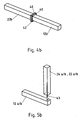
- the load beam device 30 is located in the plane of the top surface of the machine frame 10 and can as in the right part of Fig. 6a can be seen, are erected from this lying rest position in the working position. This is done by folding around the axis 39.
- the frame element 22b is removed from the strut 12b to create the free space 24b. This frame element 22b is not used in the construction of the load beam device 30.
- FIG. 6b the connecting elements or the folding mechanism are shown enlarged. It can be seen that a multi-part hinge 51 partly with the support 34a, b and partly with the Strut 12a, b is connected. The individual hinge parts are connected by a hinge pin 52.
- a load beam component 36, support 34b and beam 32 is provided in the Fig. 7a .
- the load beam component 36 is pivotally mounted and is in the left-hand illustration in the lowered rest position, in which the load beam component 36 is arranged parallel to a wall surface of the machine frame 10.
- a pivoting mechanism is shown, which allows the load beam component 36 about the axis 39 to pivot upward into the working position (see right-hand illustration of Fig. 7a ). Also in this embodiment, the frame member 22b is removed from the strut 12b to provide the necessary working space 24b. After erecting the load beam component 36, the frame member 22b is attached as a post 34a to the load beam component 36 and connected to the horizontal strut 12b and secured.
- Fig. 7b The details of the pivoting means and the connection of the strut 34a is in the Fig. 7b shown. It can be seen that the multi-part hinge 51 is connected in part to the support 34a, b and partly to the strut 12a, b. The individual hinge parts are also connected by the hinge pin 52.
Description
Die Erfindung betrifft einen Maschinenrahmen zur Aufnahme von Maschinen oder Anlagen gemäß dem Oberbegriff des Anspruchs 1.The invention relates to a machine frame for receiving machines or systems according to the preamble of claim 1.
Derartige Maschinenrahmen werden beispielsweise bei Luftverdichter-Anlagen verwendet. Luftverdichter-Anlagen werden zum Aufspüren von Erdöl- und Erdgaslagerstätten eingesetzt und müssen zu diesem Zweck auf geeignete Transportmittel, wie z.B. Lastkraftwagen oder Erkundungsschiffe verladen werden.Such machine frames are used for example in air compressor systems. Air compressor systems are used to detect oil and gas deposits and for this purpose must be adapted to suitable means of transport such as e.g. Lorries or reconnaissance vessels are loaded.
Die Anlage wird hierzu z.B. von Containerkränen am Maschinenrahmen erfasst und kann auf einfache Weise verladen und auf den Transportfahrzeugen verstaut werden.The system is for this purpose e.g. captured by container cranes on the machine frame and can be easily loaded and stowed on the transport vehicles.
Auf einem Erkundungsschiff sind solche Anlagen über längere Zeit in ständigem Einsatz und müssen daher vor Ort in Stand gehalten, gewartet und ggf. auch repariert werden. Da die Komponenten einer solchen Anlage aufgrund ihres Gewichtes nicht von Hand bewegt werden können, besteht die Notwendigkeit, Hilfsgerüste in den Bereich der schweren Bauteile zu schaffen, Mobilkräne einzusetzen oder die Bauteile in den Wirkbereich von stationären Hebezeugen zu verbringen.On a reconnaissance ship such systems are in constant use for a long time and must therefore be maintained on site, maintained and possibly also repaired. Since the components of such a plant can not be moved by hand due to their weight, there is a need to provide auxiliary scaffolding in the area of heavy components, use mobile cranes or to spend the components in the range of action of stationary hoists.
Auf Schiffen sind entweder die entsprechenden Hilfsmittel nicht vorhanden oder aus Platzgründen nicht einsetzbar, insbesondere wenn die Anlagen unter Deck angeordnet werden.On ships either the appropriate tools are not available or not usable for reasons of space, especially when the systems are located below deck.
Die
Am Rahmen kann ein H-förmiges Aufzugsgestell aus zwei Seitenträgern und einem Querträger angebracht werden.On the frame, an H-shaped elevator frame of two side rails and a cross member can be attached.
Dieser Container hat den Nachteil, dass das Aufzugsgestell bei Nichtgebrauch separat gelagert werden muss und somit zusätzlichen Stauraum benötigt. Da der Querträger dieses Aufzugsgestells zwischen der oberen Querstrebe und der unteren Querstrebe angeordnet ist, eignet er sich aufgrund seines niedrigen Einbaus nicht als Lastbalkeneinrichtung, um Instandhaltung, Wartung und Reparaturarbeiten der innerhalb des Maschinenrahmens angeordneten Maschinen oder Anlagen auf einfache Weise durchführen zu können.This container has the disadvantage that the elevator frame must be stored separately when not in use and thus requires additional storage space. Since the cross member of this elevator frame is disposed between the upper cross member and the lower cross member, it is not suitable as a load beam device due to its low installation, in order to perform maintenance, repair and maintenance of the arranged within the machine frame machinery or equipment in a simple manner.
Die
Die
Die
Die
Es ist daher Aufgabe der Erfindung, einen Maschinenrahmen bereitzustellen, mit dem Instandhaltung, Wartung und Reparaturarbeiten der innerhalb des Maschinenrahmens angeordneten Maschinen oder Anlagen auf einfache Weise durchführbar sind.It is therefore an object of the invention to provide a machine frame, with the maintenance, and maintenance Repair work within the machine frame arranged machinery or equipment can be carried out in a simple manner.
Diese Aufgabe wird mit einem Maschinenrahmen gemäß den Merkmalen des Anspruchs 1 gelöst.This object is achieved with a machine frame according to the features of claim 1.
An der Lastbalkeneinrichtung kann z.B. ein Hebezeug angebracht werden, mit dem z.B. die Maschine oder die Anlagenkomponente, die gewartet oder repariert werden soll, angehoben und bewegt werden kann. Die Lastbalkeneinrichtung wird nur dann an der oberen Horizontalstrebe angebracht, wenn sie benötigt wird.At the load bar means, e.g. a hoist with which e.g. the machine or plant component to be serviced or repaired can be lifted and moved. The load beam device is only attached to the upper horizontal strut when needed.
Nach Durchführung der erforderlichen Arbeiten kann die Lastbalkeneinrichtung wieder entfernt werden, so dass sie ein Umsetzen der Anlage oder deren Transport nicht behindert.After carrying out the necessary work, the load beam device can be removed again, so that it does not hinder the implementation of the plant or its transport.
Die Lastbalkeneinrichtung weist mindestens eine am Maschinenrahmen angeordnete Lastbalkenkomponente und/oder mindestens ein Element des Rahmens auf. Zur Installation der Lastbalkeneinrichtung werden nur Bauteile verwendet, die bereits am Maschinenrahmen vorhanden sind. Es handelt sich hierbei um Bestandteile des Rahmens, die in anderer Konfiguration zu einer Lastbalkeneinrichtung zusammengebaut werden, oder um eine Lastbalkeneinrichtung die bereits vorhanden ist und lediglich in eine Arbeitsposition gebracht werden muss. Es kann als weitere Alternative auch eine Lastbalkenkomponente am Maschinenrahmen vorgesehen sein, die sich in einer Ruheposition befindet und bei Bedarf in eine Arbeitsposition bewegbar ist und dort mittels eines Rahmenelementes zu einer Lastbalkeneinrichtung komplettiert wird. Es ist deshalb nicht notwendig, auf zusätzliche Bauteile, die entweder nur schwer verfügbar sind oder ggf. nur bedingt geeignet sind, zurückzugreifen.The load beam device has at least one load beam component arranged on the machine frame and / or at least one element of the frame. To install the load beam device only components are used, which are already present on the machine frame. These are components of the frame, which are assembled in a different configuration to a load beam device, or a load beam device which is already present and only needs to be brought into a working position. It can be provided as a further alternative, a load beam component on the machine frame, which is in a rest position and, if necessary in a working position is movable and is completed there by means of a frame member to a load beam device. It is not necessary to resort to additional components which are either difficult to obtain or may have only limited suitability.
Alle notwendigen Komponenten zur Herstellung der Lastbalkeneinrichtung sind am oder im Rahmen vorhanden und dort insbesondere unverlierbar angeordnet. Insbesondere durch die Verwendung vorhandener Rahmenelemente, aus denen die Lastbalkeneinrichtung zusammenbaubar ist, werden für das Vorhalten einer solchen Lastbalkeneinrichtung keine oder nur geringfügige Mehrkosten verursacht.All necessary components for the production of the load beam device are present on or in the frame and arranged there, in particular captive. In particular, by the use of existing frame elements from which the load beam device can be assembled, no or only minor additional costs are incurred for the provision of such load beam device.
Die Installation kann entweder von Hand oder unter Zuhilfenahme von einfachen, in der Regel vorhandener Werkzeuge, wie Schraubenschlüssel etc. vorgenommen werden.The installation can be done either by hand or with the help of simple, usually existing tools, such as wrenches, etc.
Die Lastbalkeneinrichtung kann daher vor Ort, z. B. in strukturschwachen, unzugänglichen oder unwirtlichen Regionen, wie es z. B. bei der Suche nach Bodenschätzen der Fall ist, mit den dort üblicherweise vorhandenen Mitteln installiert und verwendet werden.The load beam device can therefore locally, z. B. in structurally weak, inaccessible or inhospitable regions, as z. B. in the search for natural resources is the case, installed and used there with the usual means there.
Die Lastbalkeneinrichtung weist vorzugsweise zwei Stützen und einen die beiden Stützen verbindenden Balken auf. Es sind für diese Ausführungsform lediglich drei einfache Komponenten erforderlich, die aus am Maschinenrahmen befindlichen Bauteilen bereitgestellt werden können.The load beam device preferably has two supports and a bar connecting the two supports. There are only three simple components required for this embodiment, which can be provided from located on the machine frame components.
Mindestens eine obere Horizontalstrebe weist mindestens ein lösbar befestigtes Rahmenelement auf. Aus einem oder mehreren der oberen Horizontalstreben können Rahmenelemente herausgenommen werden, wodurch die betroffene Strebe unterbrochen wird. An den betreffenden Stellen wird der Maschinenrahmen zwar geschwächt, was jedoch insoweit vertretbar ist, als bei Wartungs- und Reparaturarbeiten die Anlage ohnehin nicht im Betrieb ist und der Maschinenrahmen somit nicht in der üblichen Weise belastet wird.At least one upper horizontal strut has at least one releasably secured frame element. From one or more of the upper horizontal struts frame elements can be removed, whereby the affected strut is interrupted. Although the machine frame is weakened at the points in question, this is justifiable to the extent that it can be justified in terms of maintenance and repair Repair work the system is not in operation anyway and thus the machine frame is not charged in the usual way.
Die lösbar befestigten Rahmenelemente sind vorzugsweise an oder in der oberen Horizontalstrebe vorgesehen, weil diese leicht zugänglich ist. Außerdem ist es vorteilhaft, wenn an der Stelle, wo die Lastbalkeneinrichtung installiert wird, unter der Lastbalkeneinrichtung ein Freiraum geschaffen wird, um die notwendigen Arbeiten durchführen zu können, insbesondere wenn an der Lastbalkeneinrichtung Hebezeuge montiert werden sollen. Durch den Ausbau des Rahmenelementes wird der nötige Arbeitsraum geschaffen.The releasably secured frame members are preferably provided on or in the upper horizontal bar, because it is easily accessible. Moreover, it is advantageous if, at the location where the load beam device is installed, a free space is created under the load beam device in order to carry out the necessary work, in particular if lifting devices are to be mounted on the load beam device. By expanding the frame element of the necessary work space is created.
Es ist deshalb von Vorteil, wenn die lösbar befestigten Rahmenelemente in den Bereichen vorgesehen sind, wo auch die reparatur- oder wartungsbedürftigen Maschinen oder Anlagenkomponenten innerhalb des Rahmengestells angeordnet sind.It is therefore advantageous if the releasably secured frame members are provided in the areas where the machines or system components requiring repair or maintenance are arranged within the frame.
Die Länge der lösbar befestigten Rahmenelemente ist auf die gewünschten Abmessungen der Lastbalkeneinrichtung abgestimmt. Es können unterschiedlich lange Rahmenelemente im Rahmen vorgesehen sein, um unterschiedlich hohe Lastbalkeneinrichtungen zusammenbauen zu können. Um mehrere unterschiedlich lange Rahmenelemente bereitstellen zu können, können diese auch an anderer Stelle als in den oberen Horizontalstreben vorgesehen sein. Lösbar befestigte Rahmenelemente können vorzugsweise auch Bestandteile von anderen Streben, insbesondere von Verbindungsstreben sein, die als Horizontal- oder Vertikalstreben ausgebildet sein können.The length of the releasably secured frame members is tuned to the desired dimensions of the load beam device. It can be provided in the frame different lengths frame members to assemble different high load beam devices can. In order to provide several frame members of different lengths, they can also be provided elsewhere than in the upper horizontal struts. Removable fastened frame members may preferably also be components of other struts, in particular of connecting struts, which may be formed as horizontal or vertical struts.
Nach Durchführung der Instandhaltungs-, Wartungs- und Reparaturarbeiten werden die Rahmenelemente wieder an ihrem ursprünglichen Ort in die Streben eingesetzt, so dass die Steifigkeit des Rahmengestells wieder hergestellt wird.After carrying out the maintenance, service and repair work, the frame elements are returned to their original position original location used in the struts, so that the rigidity of the frame is restored.
Vorrugsweise ist die Lastbalkeneinrichtung oder die Lastbalkenkomponente ist an einer Strebe von einer Ruhe- in eine Arbeitsposition und umgekehrt klappbar oder schwenkbar angeordnet. Die Lastbalkeneinrichtung oder die Lastbalkenkomponente wird bei Nichtgebrauch in ihre Ruheposition weggeschwenkt oder weggeklappt und verbleibt am Maschinenrahmen.Vorrugsweise the load beam device or the load beam component is arranged on a strut from a rest to a working position and vice versa foldable or pivotable. The load beam device or the load beam component is pivoted away when not in use in its rest position or folded away and remains on the machine frame.
Vorzugsweise erfolgt das Wegschwenken oder Wegklappen in Ruheposition in eine Ebene parallel zu einer Wandfläche des Rahmengestells.Preferably, the pivoting away or folding away in the rest position takes place in a plane parallel to a wall surface of the frame.
Die Lastbalkenkomponente weist vorzugsweise mindestens eine Stütze auf. Die Lastbalkenkomponente kann beispielsweise auch beide Stützen oder eine Stütze und den dazugehörigen Balken aufweisen. Die Lastbalkenkomponente ist vorzugsweise mit mindestens einem lösbar befestigten Rahmenelement verbindbar.The load beam component preferably has at least one support. The load beam component may, for example, also have both supports or a support and the associated beam. The load beam component is preferably connectable to at least one releasably secured frame member.
Die Lastbalkeneinrichtung besteht vorzugsweise vollständig aus lösbar befestigten Rahmenelementen.The load beam device preferably consists entirely of detachably fastened frame elements.
Die Rahmenelemente sind untereinander oder mit der Lastbalkenkomponente verschraubbar und/oder steckbar verbunden. Auf diese Weise wird der Zusammenbau und die Demontage der Lastbalkeneinrichtung erleichtert, was ohne großen Werkzeugaufwand durchführbar ist.The frame members are screwed together and / or pluggable with each other or with the Lastbalkenkomponente. In this way, the assembly and disassembly of the load beam device is facilitated, which is feasible without much tooling.
Vorzugsweise weist das Rahmenelement und/oder die Lastbalkenkomponente endseitig eine Montageplatte auf. Eine solche Montageplatte ist dazu vorgesehen, dass die zu verbindenden Bauteile miteinander beispielsweise verschraubt werden können.The frame element and / or the load beam component preferably has a mounting plate at the end. Such Mounting plate is provided so that the components to be joined together, for example, can be screwed.
Vorzugsweise weist der Maschinenrahmen die Abmessungen eines Containers auf. Dadurch wird es möglich, die Anlage mit dem Maschinenrahmen auf einem LKW oder einem Zugwagon auf einfache Weise zu transportieren. Außerdem wird dadurch der Transport auf einem Containerschiff vereinfacht.Preferably, the machine frame has the dimensions of a container. This makes it possible to easily transport the system with the machine frame on a truck or a train carriage. It also simplifies transport on a container ship.
Der Balken kann Mittel zum Befestigen von Hebezeug wie z.B. einem Flaschenzug, einem Seilzug, einem Kettenzug oder ähnlichem aufweisen. Solche Mittel sind z.B. Bohrungen im Balken, in die das betreffende Hebezeug eingehängt werden kann.The beam may include means for attaching hoists such as e.g. a pulley, a cable, a chain hoist or the like. Such means are e.g. Holes in the beam into which the hoist in question can be hung.
Der Maschinenrahmen ist vorzugsweise zur Aufnahme einer Luftverdichter-Anlage ausgebildet, die einen Kolbenkompressor aufweist.The machine frame is preferably designed for receiving an air compressor system which has a piston compressor.
Die Lastbalkeneinrichtung ist bei dieser Ausführungsform vorzugsweise im Bereich des Kolbenkompressors anbringbar. Dadurch wird es möglich, auf einfache Weise beispielsweise die Kolbenringe des Kolbenkompressors auszutauschen.The load beam device is preferably attachable in the region of the piston compressor in this embodiment. This makes it possible to easily replace, for example, the piston rings of the reciprocating compressor.
Der Maschinenrahmen ist vorzugsweise überall dort einsetzbar, wo große Maschinen oder Anlagen vorgesehen sind, wobei die Maschinen oder Anlagen oder deren Komponenten aufgrund ihres Gewichtes nicht händisch bewegt werden können. Die Bauhöhe des Maschinenrahmens beträgt vorzugsweise > 1,50 m, insbesondere > 2,0 m. Das Gewicht der Maschinen, Anlagen und deren Komponenten liegt in der Regel bei mehr als 100 kg, insbesondere bei mehr als 500 kg und kann auch bis zu mehreren tausend kg betragen.The machine frame is preferably used everywhere where large machines or facilities are provided, the machinery or equipment or its components can not be moved by hand due to their weight. The overall height of the machine frame is preferably> 1.50 m, in particular> 2.0 m. The weight of the machines, systems and their components is usually more than 100 kg, in particular more than 500 kg and can also be up to several thousand kg.
Weitere Einsatzgebiete sind beispielsweise Dampferzeugeranlagen, Kraftwerksanlagen, Rauchgasreinigungsanlagen, Gasverdichteranlagen, Papiermaschinen, Pressen, Werkzeugmaschinen, Raffinerieanlagen oder Verpackungsmaschinen.Further fields of use are, for example, steam generator plants, power plants, flue gas purification plants, gas compressor plants, paper machines, presses, machine tools, refinery plants or packaging machines.
Der Vorteil des erfindungsgemäßen Maschinenrahmens mit Lastbalkeneinrichtung besteht darin, dass er zu Zeiten des bestimmungsgemäßen Gebrauchs der Anlage bzw. der Maschine die Aufgabe erfüllt, statische und dynamische Lasten aufzunehmen und gleichzeitig zu Zeiten des Instandhaltungs-, Wartungs- und Reparaturbetriebs der Anlage bzw. Maschine dazu verwendet werden kann, eben diese Arbeiten zu jeder Zeit, an jedem Ort und unabhängig von zusätzlichen Hilfsgerüsten durchzuführen.The advantage of the machine frame according to the invention with load beam device is that it fulfills the task of picking up static and dynamic loads at times when the plant or machine is being used as intended and at the same time during maintenance, service and repair operations of the plant or machine can be used to perform just this work at any time, in any place and independently of additional scaffolding.
Beispielhafte Ausführungsformen der Erfindung werden nachfolgend anhand der Zeichnungen näher erläutert. Es zeigen:
- Fig. 1
- eine perspektivische Darstellung einer Luftverdichter-Anlage mit dem dazugehörigen Maschinenrahmen,
- Fig. 2
- einen perspektivische vereinfachte Darstellung des Maschinenrahmens ohne Lastbalkeneinrichtung,
- Fig. 3
- den in
Fig. 2 gezeigten Maschinenrahmen, an dem eine Lastbalkeneinrichtung angebracht ist, - Fig. 4a - 7a
- verschiedene Ausführungen von Lastbalkeneinrichtungen,
- Fig. 4b - 7b
- vergrößerte Darstellungen der zu den
Figuren 4a bis 7a gehörenden Verbindungen.
- Fig. 1
- a perspective view of an air compressor plant with the associated machine frame,
- Fig. 2
- a simplified perspective view of the machine frame without load beam device,
- Fig. 3
- the in
Fig. 2 shown machine frame, on which a load beam device is mounted, - Fig. 4a - 7a
- various designs of load beam devices,
- Fig. 4b - 7b
- enlarged representations of the
FIGS. 4a to 7a belonging connections.
In
Der Maschinenrahmen 10 weist untere Horizontalstreben 14a-d, obere Horizontalstreben 12a-d sowie an den vier Ecken Vertikalstreben 16a-d auf. Ferner sind horizontale Verbindungsstege 18a, b zwischen den oberen Horizontalstreben 12a und 12c vorgesehen. Im Bereich zwischen den Vertikalstreben 16a und 16b befinden sich weitere Vertikalstreben als Verbindungsstreben 20a, b, c, die wiederum über horizontale Verbindungsstreben 18c miteinander verbunden sind und auf diese Weise eine zusätzliche Versteifung des Gesamtrahmens bewirken. Die oberen Horizontalstreben 12a-d weisen lösbar befestigte Rahmenelemente 22a-d auf.The
In
In der
Die beiden Stützen 34a, b der Lastbalkeneinrichtung 30 werden durch die ausgebauten Rahmenelemente 22a und 22c gebildet. Damit definieren die Rahmenelemente 22a, c die Höhe der Lastbalkeneinrichtung.The two
Dadurch dass das Rahmenelement 22b aus der Horizontalstrebe 12b entfernt worden ist und für die Lastbalkeneinrichtung verwendet wurde, wird unterhalb der Lastbalkeneinrichtung ein Freiraum 24b und somit der entsprechende Arbeitsraum geschaffen, in dem nicht dargestellte Hebezeuge nach unten abgesenkt werden können, um entsprechende Komponenten oder Anlagenteile der betreffenden Anlage erfassen zu können. Zu diesem Zweck weist der Balken 32 Befestigungsmittel 50 in Form von Bohrungen auf, in die Hebezeuge eingehängt werden können.The fact that the
An den Stellen, wo die Horizontalstreben 12a und 12c unterbrochen sind, sind ebenfalls Freiräume 24a, 24c gebildet worden. Nach erfolgten Wartungs- und Instandhaltungsarbeiten kann die Lastbalkeneinrichtung 30 wieder rückgebaut werden, indem die betreffenden Rahmenelemente 22a, b und c an ihren ursprünglichen Ort in den Horizontalstreben 12a, b und c eingesetzt werden.At the locations where the
In der
In der
In der
In der
In der
In der
In der
Am unteren Ende der Stütze 34b ist ein Schwenkmechanismus dargestellt, der es erlaubt, die Lastbalkenkomponente 36 um die Achse 39 nach oben in die Arbeitsposition zu verschwenken (siehe rechte Darstellung der
Die Einzelheiten der Schwenkeinrichtung und der Verbindung der Strebe 34a ist in der
- 11
- Luftverdichter-AnlageAir compressor plant
- 22
- Kolbenkompressorpiston compressor
- 33
- Antriebsmotordrive motor
- 44
- Schraubenverdichterscrew compressors
- 1010
- Maschinenrahmenmachine frame
- 12a-d12a-d
- obere Horizontalstrebeupper horizontal strut
- 14a-d14a-d
- untere Horizontalstrebelower horizontal strut
- 16a-d16a-d
- Vertikalstrebevertical strut
- 18a-c18a-c
- horizontale Verbindungsstrebehorizontal connecting strut
- 20a-c20a-c
- vertikale Verbindungsstrebevertical connecting strut
- 22a-d22a-d
- Rahmenelementframe element
- 24a-c24a-c
- Freiraumfree space
- 3030
- LastbalkeneinrichtungLast beam means
- 3232
- Balkenbar
- 34a, b34a, b
- Stützesupport
- 3636
- LastbalkenkomponenteLoading beam component
- 3939
- Schwenkachseswivel axis
- 4040
- Montageplattemounting plate
- 4242
- Schraubescrew
- 4343
- Domcathedral
- 5050
- Befestigungsmittelfastener
- 5151
- Scharnierhinge
- 5252
- Scharnierbolzenhinge pin
Claims (14)
- An initial machine frame (10) for receiving machines or plants with a 3-dimensional framework having vertical struts (16a-d) and having lower and upper horizontal struts (12a-d, 14a-d), the initial machine frame being capable of conversion into a machine frame having a load beam device using only components that are already present on the initial machine frame, characterised in that the initial machine frame has at least one upper horizontal strut with at least one detachably fastened frame element that is part of the horizontal strut, so that, after removal, a horizontal strut having a free space may be formed in the machine frame.
- An initial machine frame according to claim 1, characterised in that the load beam device (30) may be mounted on an upper horizontal strut (12a-d).
- An initial machine frame according to claim 1 or 2, characterised in that the load beam device (30) has at least one load beam component (36) that is disposed on the initial machine frame (10) and/or has at least one element (22a-d) of the initial machine frame (10).
- An initial machine frame according to any one of claims 1 to 3, characterised in that the load beam device (30) has two supports (34a, b) and a beam (32) connecting the two supports (34a, b).
- An initial machine frame according to any one of claims 1 to 4, characterised in that the load beam device (30) is mounted in the region of the detachably fastened frame element (22a-d).
- An initial machine frame according to any one of claims 1 to 5, characterised in that the load beam device (30) or the load beam component (36) is arranged at a strut (12a-d, 14a-d, 16a-d) to be folded or pivoted from a resting position into a working position and vice versa.
- An initial machine frame according to any one of claims 3 to 6, characterised in that the load beam component (36) has at least one support (34a, b).
- An initial machine frame according to any one of claims 3 to 7, characterised in that the load beam component (36) is connectable to at least one detachably fastened frame element (22a-d).
- An initial machine frame according to any one of claims 1 to 8, characterised in that the load beam device (30) consists of detachably fastened frame elements (22a-d).
- An initial machine frame according to any one of claims 3 to 9, characterised in that the frame elements (22a-d) are connected to one another or to the load beam component (36) in a bolt-on and/or plug-in manner.
- An initial machine frame according to any one of claims 3 to 10, characterised in that the frame element (22a-d) and/or the load beam component (36, 38) has at the end thereof a mounting plate (40).
- An initial machine frame according to any one of claims 1 to 11, characterised in that the beam (32) has means for fastening hoisting gear.
- An initial machine frame according to any one of claims 1 to 12, characterised in that it is configured to receive an air compressor unit (1) having a piston compressor (2).
- An initial machine frame according to claim 13, characterised in that the load beam device (30) is mountable in the region of the piston compressor (2).
Priority Applications (1)
| Application Number | Priority Date | Filing Date | Title |
|---|---|---|---|
| EP20080153496 EP2105649B1 (en) | 2008-03-28 | 2008-03-28 | Machine framework |
Applications Claiming Priority (1)
| Application Number | Priority Date | Filing Date | Title |
|---|---|---|---|
| EP20080153496 EP2105649B1 (en) | 2008-03-28 | 2008-03-28 | Machine framework |
Publications (2)
| Publication Number | Publication Date |
|---|---|
| EP2105649A1 EP2105649A1 (en) | 2009-09-30 |
| EP2105649B1 true EP2105649B1 (en) | 2013-01-30 |
Family
ID=39684438
Family Applications (1)
| Application Number | Title | Priority Date | Filing Date |
|---|---|---|---|
| EP20080153496 Not-in-force EP2105649B1 (en) | 2008-03-28 | 2008-03-28 | Machine framework |
Country Status (1)
| Country | Link |
|---|---|
| EP (1) | EP2105649B1 (en) |
Families Citing this family (1)
| Publication number | Priority date | Publication date | Assignee | Title |
|---|---|---|---|---|
| DE102014106333B4 (en) * | 2014-05-07 | 2023-02-16 | Pester Pac Automation Gmbh | contraption |
Family Cites Families (8)
| Publication number | Priority date | Publication date | Assignee | Title |
|---|---|---|---|---|
| GB1247349A (en) * | 1968-06-17 | 1971-09-22 | Norman Thomas Tamplin | Bulk container unit |
| DE2165203A1 (en) * | 1971-12-29 | 1973-07-05 | Smitka Guenter | BOX FRAME FOR DEVICE CONSTRUCTION, ESPECIALLY AIR CONDITIONING OR SUPPLY AND EXHAUST UNITS |
| BE793670A (en) * | 1972-02-01 | 1973-05-02 | Magyar Hajo Es Darugyar | CONSTRUCTION OF FREESTANDING CHASSIS AND LAYOUT FOR A MOBILE THERMAL PLANT, WHICH CAN BE MOVED IN THE MOUNTED STATE |
| DE4333048C2 (en) * | 1993-09-29 | 1997-01-30 | Abb Patent Gmbh | Frame for holding machines and devices |
| CH692738A5 (en) * | 1997-10-17 | 2002-10-15 | Ruag Land Systems | Container, for the movement of goods, has two longitudinal beams at the platform to act as rails to ride on rollers at the freight vehicle for loading/unloading, and also have pockets for a forklift truck tines |
| DE19953900A1 (en) * | 1999-11-10 | 2001-05-17 | Sabatec Saugbaggertechnologie | Suction bagger especially for pick-up of soil has superstructures on separate support device that can be attached in detachable fashion on chassis of vehicle and removed therefrom |
| DE10261274B4 (en) * | 2002-12-27 | 2005-04-21 | Eisenmann Maschinenbau Gmbh & Co. Kg | Frame part for the basic frame of an industrial plant |
| AT9916U1 (en) * | 2006-08-16 | 2008-05-15 | Leobersdorfer Maschf | MULTI-STAGE COMPRESSOR |
-
2008
- 2008-03-28 EP EP20080153496 patent/EP2105649B1/en not_active Not-in-force
Also Published As
| Publication number | Publication date |
|---|---|
| EP2105649A1 (en) | 2009-09-30 |
Similar Documents
| Publication | Publication Date | Title |
|---|---|---|
| EP1935833A1 (en) | Framework unit for a large mobile crane and method for its erection | |
| EP1348667A2 (en) | Lifting device for vehicles, assembly units, machines or similar | |
| WO2011076238A1 (en) | Adjustable transport feet | |
| DE3704598A1 (en) | MOVING SCAFFOLDING | |
| DE102008032739A1 (en) | Mobile crane e.g. crawler crane, has connection elements at undercarriage in area of rotary rim and provided for detachable connection with lateral support units, where undercarriage has rim on which upper carriage is mounted at rotary axis | |
| EP2531437B1 (en) | Method for producing a track and track for a track lifting device | |
| WO2015000635A1 (en) | Overhead conveying device having support framework modules | |
| DE3420737A1 (en) | Auxiliary apparatus for vertically adjustable scaffolding | |
| DE1584525B1 (en) | Battery formwork | |
| EP2105649B1 (en) | Machine framework | |
| EP0464062B1 (en) | Device for inspecting the underside of bridges | |
| DE102012209988A1 (en) | Sub-module for a mobile drilling rig and method for assembling and dismantling such sub-modules | |
| DE4034053C2 (en) | ||
| DE3411299C2 (en) | ||
| DE4000288A1 (en) | Wall mounted crane assembly - has telescopic horizontal arm which can be swung about vertical axis | |
| DE102017200367A1 (en) | A method of assembling and / or disassembling components of a turbine housing turbine, adapter and system for use in the method and use of an adapter | |
| DE20321855U1 (en) | Steel tower for a wind turbine | |
| DE102008029872B4 (en) | Mobile building | |
| EP2472071B1 (en) | Industrial plant with noise attenuation hood | |
| DE3305323A1 (en) | SHIP WITH A PIPELINE SYSTEM LOCATED ON THE INNER FLOOR | |
| EP3947838A1 (en) | Modular frame system for stacking assemblies in industrial system construction | |
| EP3276099B1 (en) | Transport container | |
| DE3723452A1 (en) | Sliding tarpaulin frame for goods vehicles | |
| DE102019217175B4 (en) | Mobile folding frame for a transport vehicle and mobile press arrangement with such a folding frame | |
| DE102008006803B4 (en) | Method for loading a hold |
Legal Events
| Date | Code | Title | Description |
|---|---|---|---|
| PUAI | Public reference made under article 153(3) epc to a published international application that has entered the european phase |
Free format text: ORIGINAL CODE: 0009012 |
|
| 17P | Request for examination filed |
Effective date: 20090213 |
|
| AK | Designated contracting states |
Kind code of ref document: A1 Designated state(s): AT BE BG CH CY CZ DE DK EE ES FI FR GB GR HR HU IE IS IT LI LT LU LV MC MT NL NO PL PT RO SE SI SK TR |
|
| AX | Request for extension of the european patent |
Extension state: AL BA MK RS |
|
| AKX | Designation fees paid |
Designated state(s): AT BE BG CH CY CZ DE DK EE ES FI FR GB GR HR HU IE IS IT LI LT LU LV MC MT NL NO PL PT RO SE SI SK TR |
|
| 17Q | First examination report despatched |
Effective date: 20100729 |
|
| GRAP | Despatch of communication of intention to grant a patent |
Free format text: ORIGINAL CODE: EPIDOSNIGR1 |
|
| GRAS | Grant fee paid |
Free format text: ORIGINAL CODE: EPIDOSNIGR3 |
|
| GRAP | Despatch of communication of intention to grant a patent |
Free format text: ORIGINAL CODE: EPIDOSNIGR1 |
|
| GRAA | (expected) grant |
Free format text: ORIGINAL CODE: 0009210 |
|
| AK | Designated contracting states |
Kind code of ref document: B1 Designated state(s): AT BE BG CH CY CZ DE DK EE ES FI FR GB GR HR HU IE IS IT LI LT LU LV MC MT NL NO PL PT RO SE SI SK TR |
|
| REG | Reference to a national code |
Ref country code: GB Ref legal event code: FG4D Free format text: NOT ENGLISH |
|
| REG | Reference to a national code |
Ref country code: CH Ref legal event code: EP |
|
| REG | Reference to a national code |
Ref country code: AT Ref legal event code: REF Ref document number: 595776 Country of ref document: AT Kind code of ref document: T Effective date: 20130215 Ref country code: CH Ref legal event code: EP |
|
| REG | Reference to a national code |
Ref country code: IE Ref legal event code: FG4D Free format text: LANGUAGE OF EP DOCUMENT: GERMAN |
|
| REG | Reference to a national code |
Ref country code: DE Ref legal event code: R096 Ref document number: 502008009189 Country of ref document: DE Effective date: 20130328 |
|
| REG | Reference to a national code |
Ref country code: NO Ref legal event code: T2 Effective date: 20130130 |
|
| REG | Reference to a national code |
Ref country code: LT Ref legal event code: MG4D |
|
| REG | Reference to a national code |
Ref country code: NL Ref legal event code: VDEP Effective date: 20130130 |
|
| PG25 | Lapsed in a contracting state [announced via postgrant information from national office to epo] |
Ref country code: LT Free format text: LAPSE BECAUSE OF FAILURE TO SUBMIT A TRANSLATION OF THE DESCRIPTION OR TO PAY THE FEE WITHIN THE PRESCRIBED TIME-LIMIT Effective date: 20130130 Ref country code: ES Free format text: LAPSE BECAUSE OF FAILURE TO SUBMIT A TRANSLATION OF THE DESCRIPTION OR TO PAY THE FEE WITHIN THE PRESCRIBED TIME-LIMIT Effective date: 20130511 Ref country code: IS Free format text: LAPSE BECAUSE OF FAILURE TO SUBMIT A TRANSLATION OF THE DESCRIPTION OR TO PAY THE FEE WITHIN THE PRESCRIBED TIME-LIMIT Effective date: 20130530 Ref country code: SE Free format text: LAPSE BECAUSE OF FAILURE TO SUBMIT A TRANSLATION OF THE DESCRIPTION OR TO PAY THE FEE WITHIN THE PRESCRIBED TIME-LIMIT Effective date: 20130130 Ref country code: BG Free format text: LAPSE BECAUSE OF FAILURE TO SUBMIT A TRANSLATION OF THE DESCRIPTION OR TO PAY THE FEE WITHIN THE PRESCRIBED TIME-LIMIT Effective date: 20130430 |
|
| PG25 | Lapsed in a contracting state [announced via postgrant information from national office to epo] |
Ref country code: GR Free format text: LAPSE BECAUSE OF FAILURE TO SUBMIT A TRANSLATION OF THE DESCRIPTION OR TO PAY THE FEE WITHIN THE PRESCRIBED TIME-LIMIT Effective date: 20130501 Ref country code: PL Free format text: LAPSE BECAUSE OF FAILURE TO SUBMIT A TRANSLATION OF THE DESCRIPTION OR TO PAY THE FEE WITHIN THE PRESCRIBED TIME-LIMIT Effective date: 20130130 Ref country code: PT Free format text: LAPSE BECAUSE OF FAILURE TO SUBMIT A TRANSLATION OF THE DESCRIPTION OR TO PAY THE FEE WITHIN THE PRESCRIBED TIME-LIMIT Effective date: 20130530 Ref country code: LV Free format text: LAPSE BECAUSE OF FAILURE TO SUBMIT A TRANSLATION OF THE DESCRIPTION OR TO PAY THE FEE WITHIN THE PRESCRIBED TIME-LIMIT Effective date: 20130130 Ref country code: FI Free format text: LAPSE BECAUSE OF FAILURE TO SUBMIT A TRANSLATION OF THE DESCRIPTION OR TO PAY THE FEE WITHIN THE PRESCRIBED TIME-LIMIT Effective date: 20130130 Ref country code: SI Free format text: LAPSE BECAUSE OF FAILURE TO SUBMIT A TRANSLATION OF THE DESCRIPTION OR TO PAY THE FEE WITHIN THE PRESCRIBED TIME-LIMIT Effective date: 20130130 Ref country code: NL Free format text: LAPSE BECAUSE OF FAILURE TO SUBMIT A TRANSLATION OF THE DESCRIPTION OR TO PAY THE FEE WITHIN THE PRESCRIBED TIME-LIMIT Effective date: 20130130 |
|
| BERE | Be: lapsed |
Owner name: NEUMAN & ESSER DEUTSCHLAND G.M.B.H. & CO. KG Effective date: 20130331 |
|
| PG25 | Lapsed in a contracting state [announced via postgrant information from national office to epo] |
Ref country code: HR Free format text: LAPSE BECAUSE OF FAILURE TO SUBMIT A TRANSLATION OF THE DESCRIPTION OR TO PAY THE FEE WITHIN THE PRESCRIBED TIME-LIMIT Effective date: 20130130 |
|
| PG25 | Lapsed in a contracting state [announced via postgrant information from national office to epo] |
Ref country code: MC Free format text: LAPSE BECAUSE OF NON-PAYMENT OF DUE FEES Effective date: 20130331 Ref country code: SK Free format text: LAPSE BECAUSE OF FAILURE TO SUBMIT A TRANSLATION OF THE DESCRIPTION OR TO PAY THE FEE WITHIN THE PRESCRIBED TIME-LIMIT Effective date: 20130130 Ref country code: CZ Free format text: LAPSE BECAUSE OF FAILURE TO SUBMIT A TRANSLATION OF THE DESCRIPTION OR TO PAY THE FEE WITHIN THE PRESCRIBED TIME-LIMIT Effective date: 20130130 Ref country code: RO Free format text: LAPSE BECAUSE OF FAILURE TO SUBMIT A TRANSLATION OF THE DESCRIPTION OR TO PAY THE FEE WITHIN THE PRESCRIBED TIME-LIMIT Effective date: 20130130 Ref country code: EE Free format text: LAPSE BECAUSE OF FAILURE TO SUBMIT A TRANSLATION OF THE DESCRIPTION OR TO PAY THE FEE WITHIN THE PRESCRIBED TIME-LIMIT Effective date: 20130130 Ref country code: DK Free format text: LAPSE BECAUSE OF FAILURE TO SUBMIT A TRANSLATION OF THE DESCRIPTION OR TO PAY THE FEE WITHIN THE PRESCRIBED TIME-LIMIT Effective date: 20130130 |
|
| REG | Reference to a national code |
Ref country code: CH Ref legal event code: PL |
|
| PG25 | Lapsed in a contracting state [announced via postgrant information from national office to epo] |
Ref country code: CY Free format text: LAPSE BECAUSE OF FAILURE TO SUBMIT A TRANSLATION OF THE DESCRIPTION OR TO PAY THE FEE WITHIN THE PRESCRIBED TIME-LIMIT Effective date: 20130130 |
|
| PLBE | No opposition filed within time limit |
Free format text: ORIGINAL CODE: 0009261 |
|
| STAA | Information on the status of an ep patent application or granted ep patent |
Free format text: STATUS: NO OPPOSITION FILED WITHIN TIME LIMIT |
|
| REG | Reference to a national code |
Ref country code: FR Ref legal event code: ST Effective date: 20131129 |
|
| PG25 | Lapsed in a contracting state [announced via postgrant information from national office to epo] |
Ref country code: IT Free format text: LAPSE BECAUSE OF FAILURE TO SUBMIT A TRANSLATION OF THE DESCRIPTION OR TO PAY THE FEE WITHIN THE PRESCRIBED TIME-LIMIT Effective date: 20130130 |
|
| REG | Reference to a national code |
Ref country code: IE Ref legal event code: MM4A |
|
| 26N | No opposition filed |
Effective date: 20131031 |
|
| REG | Reference to a national code |
Ref country code: DE Ref legal event code: R119 Ref document number: 502008009189 Country of ref document: DE Effective date: 20131001 |
|
| PG25 | Lapsed in a contracting state [announced via postgrant information from national office to epo] |
Ref country code: LI Free format text: LAPSE BECAUSE OF NON-PAYMENT OF DUE FEES Effective date: 20130331 Ref country code: CH Free format text: LAPSE BECAUSE OF NON-PAYMENT OF DUE FEES Effective date: 20130331 Ref country code: DE Free format text: LAPSE BECAUSE OF NON-PAYMENT OF DUE FEES Effective date: 20131001 Ref country code: BE Free format text: LAPSE BECAUSE OF NON-PAYMENT OF DUE FEES Effective date: 20130331 Ref country code: FR Free format text: LAPSE BECAUSE OF NON-PAYMENT OF DUE FEES Effective date: 20130402 Ref country code: IE Free format text: LAPSE BECAUSE OF NON-PAYMENT OF DUE FEES Effective date: 20130328 |
|
| PGFP | Annual fee paid to national office [announced via postgrant information from national office to epo] |
Ref country code: NO Payment date: 20140324 Year of fee payment: 7 |
|
| REG | Reference to a national code |
Ref country code: AT Ref legal event code: MM01 Ref document number: 595776 Country of ref document: AT Kind code of ref document: T Effective date: 20130328 |
|
| PGFP | Annual fee paid to national office [announced via postgrant information from national office to epo] |
Ref country code: GB Payment date: 20140324 Year of fee payment: 7 |
|
| PG25 | Lapsed in a contracting state [announced via postgrant information from national office to epo] |
Ref country code: MT Free format text: LAPSE BECAUSE OF FAILURE TO SUBMIT A TRANSLATION OF THE DESCRIPTION OR TO PAY THE FEE WITHIN THE PRESCRIBED TIME-LIMIT Effective date: 20130130 |
|
| PG25 | Lapsed in a contracting state [announced via postgrant information from national office to epo] |
Ref country code: AT Free format text: LAPSE BECAUSE OF NON-PAYMENT OF DUE FEES Effective date: 20130328 |
|
| PG25 | Lapsed in a contracting state [announced via postgrant information from national office to epo] |
Ref country code: TR Free format text: LAPSE BECAUSE OF FAILURE TO SUBMIT A TRANSLATION OF THE DESCRIPTION OR TO PAY THE FEE WITHIN THE PRESCRIBED TIME-LIMIT Effective date: 20130130 |
|
| PG25 | Lapsed in a contracting state [announced via postgrant information from national office to epo] |
Ref country code: HU Free format text: LAPSE BECAUSE OF FAILURE TO SUBMIT A TRANSLATION OF THE DESCRIPTION OR TO PAY THE FEE WITHIN THE PRESCRIBED TIME-LIMIT; INVALID AB INITIO Effective date: 20080328 Ref country code: LU Free format text: LAPSE BECAUSE OF NON-PAYMENT OF DUE FEES Effective date: 20130328 |
|
| REG | Reference to a national code |
Ref country code: NO Ref legal event code: MMEP |
|
| GBPC | Gb: european patent ceased through non-payment of renewal fee |
Effective date: 20150328 |
|
| PG25 | Lapsed in a contracting state [announced via postgrant information from national office to epo] |
Ref country code: NO Free format text: LAPSE BECAUSE OF NON-PAYMENT OF DUE FEES Effective date: 20150331 Ref country code: GB Free format text: LAPSE BECAUSE OF NON-PAYMENT OF DUE FEES Effective date: 20150328 |