EP2105612A2 - Scroll compressor - Google Patents
Scroll compressor Download PDFInfo
- Publication number
- EP2105612A2 EP2105612A2 EP09154970A EP09154970A EP2105612A2 EP 2105612 A2 EP2105612 A2 EP 2105612A2 EP 09154970 A EP09154970 A EP 09154970A EP 09154970 A EP09154970 A EP 09154970A EP 2105612 A2 EP2105612 A2 EP 2105612A2
- Authority
- EP
- European Patent Office
- Prior art keywords
- eccentric shaft
- scroll
- spring member
- eccentric
- slide bush
- Prior art date
- Legal status (The legal status is an assumption and is not a legal conclusion. Google has not performed a legal analysis and makes no representation as to the accuracy of the status listed.)
- Withdrawn
Links
Images

Classifications
-
- F—MECHANICAL ENGINEERING; LIGHTING; HEATING; WEAPONS; BLASTING
- F04—POSITIVE - DISPLACEMENT MACHINES FOR LIQUIDS; PUMPS FOR LIQUIDS OR ELASTIC FLUIDS
- F04C—ROTARY-PISTON, OR OSCILLATING-PISTON, POSITIVE-DISPLACEMENT MACHINES FOR LIQUIDS; ROTARY-PISTON, OR OSCILLATING-PISTON, POSITIVE-DISPLACEMENT PUMPS
- F04C18/00—Rotary-piston pumps specially adapted for elastic fluids
- F04C18/02—Rotary-piston pumps specially adapted for elastic fluids of arcuate-engagement type, i.e. with circular translatory movement of co-operating members, each member having the same number of teeth or tooth-equivalents
- F04C18/0207—Rotary-piston pumps specially adapted for elastic fluids of arcuate-engagement type, i.e. with circular translatory movement of co-operating members, each member having the same number of teeth or tooth-equivalents both members having co-operating elements in spiral form
- F04C18/0215—Rotary-piston pumps specially adapted for elastic fluids of arcuate-engagement type, i.e. with circular translatory movement of co-operating members, each member having the same number of teeth or tooth-equivalents both members having co-operating elements in spiral form where only one member is moving
-
- F—MECHANICAL ENGINEERING; LIGHTING; HEATING; WEAPONS; BLASTING
- F04—POSITIVE - DISPLACEMENT MACHINES FOR LIQUIDS; PUMPS FOR LIQUIDS OR ELASTIC FLUIDS
- F04C—ROTARY-PISTON, OR OSCILLATING-PISTON, POSITIVE-DISPLACEMENT MACHINES FOR LIQUIDS; ROTARY-PISTON, OR OSCILLATING-PISTON, POSITIVE-DISPLACEMENT PUMPS
- F04C28/00—Control of, monitoring of, or safety arrangements for, pumps or pumping installations specially adapted for elastic fluids
- F04C28/18—Control of, monitoring of, or safety arrangements for, pumps or pumping installations specially adapted for elastic fluids characterised by varying the volume of the working chamber
- F04C28/22—Control of, monitoring of, or safety arrangements for, pumps or pumping installations specially adapted for elastic fluids characterised by varying the volume of the working chamber by changing the eccentricity between cooperating members
-
- F—MECHANICAL ENGINEERING; LIGHTING; HEATING; WEAPONS; BLASTING
- F04—POSITIVE - DISPLACEMENT MACHINES FOR LIQUIDS; PUMPS FOR LIQUIDS OR ELASTIC FLUIDS
- F04C—ROTARY-PISTON, OR OSCILLATING-PISTON, POSITIVE-DISPLACEMENT MACHINES FOR LIQUIDS; ROTARY-PISTON, OR OSCILLATING-PISTON, POSITIVE-DISPLACEMENT PUMPS
- F04C29/00—Component parts, details or accessories of pumps or pumping installations, not provided for in groups F04C18/00 - F04C28/00
- F04C29/0042—Driving elements, brakes, couplings, transmissions specially adapted for pumps
- F04C29/005—Means for transmitting movement from the prime mover to driven parts of the pump, e.g. clutches, couplings, transmissions
- F04C29/0071—Couplings between rotors and input or output shafts acting by interengaging or mating parts, i.e. positive coupling of rotor and shaft
Definitions
- the present invention relates to a scroll compressor in which laps are formed on the mutually facing faces of a fixed scroll and a mirror plate of an orbit scroll which revolves in the orbit with respect to the fixed scroll, and the laps are engaged with each other to form a plurality of compression chambers.
- this type of scroll compressor has a fixed scroll and an orbit scroll which revolves in the orbit with respect to this fixed scroll, spiral laps are formed on the mutually facing faces of the fixed scroll and a mirror plate of the orbit scroll, and the laps are engaged with each other to form a plurality of compression chambers.
- a slide bush is interposed on an eccentric shaft of a motor which drives the orbit scroll.
- This slide bush has a slide face forming a predetermined angle with respect to the direction of gas load of a gas in each compression chamber. When the load of the gas in the compression chamber is applied, the eccentric amount of the eccentric shaft increases.
- the slide face can exert the component force of the gas load to increase the eccentric amount, and hence seal properties between both the laps of the fixed scroll and the orbit scroll can be improved to improve the performance of the compressor (e.g., see Japanese Patent Application Laid-Open No. 7-71386 ) (Patent Document 1)).
- a compressor is developed in which a spring member is interposed between the slide bush and the eccentric shaft, and the spring member presses the eccentric shaft in an eccentric direction, to decrease the eccentric amount at a start, thereby decreasing a load at the start.
- the eccentric amount decreases at a stop, and a clearance between both the laps increases, so that the start load can be decreased.
- the present invention has been developed to solve such a conventional technical problem, and an object thereof is to stabilize the moving of the orbit scroll while suppressing the start load of the scroll compressor.
- a scroll compressor comprises: a fixed scroll; and an orbit scroll which revolves in the orbit with respect to this fixed scroll, spiral laps being formed on the mutually facing faces of the fixed scroll and a mirror plate of the orbit scroll, respectively, the laps being engaged with each other to form a plurality of compression chambers, an eccentric shaft of a motor which drives the orbit scroll being provided with a slide bush having a slide face forming a predetermined angle with respect to the direction of gas load of a gas in each compression chamber, so that when the load of the gas in the compression chamber is applied, the eccentric amount of the eccentric shaft increases, the scroll compressor further comprising: a spring member interposed between the slide bush and the eccentric shaft and configured to constantly urge the eccentric shaft to decrease the eccentric amount of the eccentric shaft, characterized in that this spring member urges the eccentric shaft to press the eccentric shaft onto the slide face of the slide bush.
- the present invention of the first aspect further comprises: a spring receiving portion formed in the inner surface of the slide bush to receive the spring member, characterized in that the spring receiving portion on the side of the orbit scroll is provided with a closing portion which regulates the movement of the spring member.
- the scroll compressor comprises the fixed scroll, and the orbit scroll which revolves in the orbit with respect to this fixed scroll.
- the spiral laps are formed on the mutually facing faces of the fixed scroll and the mirror plate of the orbit scroll, respectively, and the laps are engaged with each other to form a plurality of compression chambers.
- the eccentric shaft of the motor which drives the orbit scroll is provided with the slide bush having the slide face forming the predetermined angle with respect to the direction of gas load of the gas in each compression chamber, so that when the load of the gas in the compression chamber is applied, the eccentric amount of the eccentric shaft increases.
- the scroll compressor including such a constitution further comprises the spring member interposed between the slide bush and the eccentric shaft and configured to constantly urge the eccentric shaft to decrease the eccentric amount of the eccentric shaft. Therefore, the eccentric amount at a stop is small, a clearance between both the laps increases, and a load at a start can be decreased.
- the slide bush forms the predetermined angle with respect to the direction of gas load of the slide face, thereby generating a component force, and the slide bush moves in a direction where the eccentric amount of the eccentric shaft increases, so that an adequate eccentric amount can be obtained.
- the spring member urges the eccentric shaft to press the eccentric shaft onto the slide face of the slide bush, the eccentric shaft can constantly be pressed onto the slide face of the slide bush, to come in close contact with the slide face. In consequence, it is possible to securely eliminate a disadvantage that the slide face of the slide bush comes away from the eccentric shaft to cause backlash.
- the moving of the orbit scroll can be stabilized, and the performance and the reliability of the scroll compressor can be improved.
- the first aspect of the present invention further comprises the spring receiving portion formed in the inner surface of the slide bush to receive the spring member, and the spring receiving portion on the side of the orbit scroll is provided with a closing portion which regulates the movement of the spring member. Therefore, the closing portion can avoid in advance a disadvantage that the spring member jumps out toward the orbit scroll.
- FIG. 1 is a vertical side view of one embodiment of a scroll compressor (Embodiment 1);
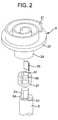
- FIG. 2 is an exploded diagram around an eccentric shaft of a motor of the scroll compressor of FIG. 1 ;
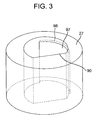
- FIG. 3 is an enlarged view of a slide bush of FIG. 2 ;
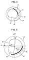
- FIG. 4 is a sectional plan view of the eccentric shaft including a spring member of the present invention (at a start);
- FIG. 5 is an enlarged view of FIG. 4 ;
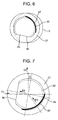
- FIG. 6 is a sectional plan view of the eccentric shaft including the spring member of the present invention (during an operation).
- FIG. 7 is an enlarged view of FIG. 6 .
- the present invention has been developed to eliminate a problem that the moving of an orbit scroll becomes unstable, for example, a problem that the slide face of a slide bush comes away from an eccentric shaft during an operation, in a scroll compressor in which a spring member is interposed between the slide bush and the eccentric shaft, and presses the eccentric shaft in an eccentric direction, to obtain the variable eccentric amount of the eccentric shaft.
- a problem to stabilize the moving of the orbit scroll while suppressing the start load of the scroll compressor is realized by interposing, between the slide bush and the eccentric shaft, the spring member which constantly urges the eccentric shaft to decrease the eccentric amount of the eccentric shaft and which urges the eccentric shaft to press the eccentric shaft onto the slide face of the slide bush.
- FIG. 1 shows a vertical side view of one embodiment of a scroll compressor to which the present invention is applied
- FIG. 2 shows an exploded diagram around an eccentric shaft 23 of a shaft 5 of the motor element 3.
- reference numeral 1 is a sealed container.
- This sealed container 1 is constituted of a container main body 1A having a vertically long cylindrical shape, and an end cap 1B and a bottom cap 1C fixedly welded to both ends (both of upper and lower ends) of this container main body 1A and each substantially having a bowl-like shape.
- a partition plate 10 which vertically partitions a space in the sealed container 1. That is, the inside of the sealed container 1 is partitioned into an upper space 11 and a lower space 12 by the partition plate 10.
- a bottom portion (i.e., the inner surface of the bottom cap 1C) 65 of the space 12 is an oil reservoir in which a lubricant for lubricating the compression element 2 and the like is received.
- a support frame 4 is received between this compression element 2 and the motor element 3 in the sealed container 1, and this support frame 4 is provided with a bearing 6 and a boss receiving portion 22 in the center of the support frame.
- This bearing 6 supports the tip (the upper end) of the shaft 5, and is formed to protrude downwards from the center of one surface (the lower surface) of the support frame 4.
- the boss receiving portion 22 receives a boss 24 of an orbit scroll 8 described later, and is formed by depressing downwards the center of the other surface (the upper surface) of the support frame 4.
- the tip (the upper end) of the shaft 5 is provided with the eccentric shaft 23.
- the center of this eccentric shaft 23 is provided to deviate from the shaft center of the shaft 5 eccentrically, and this eccentric shaft is drivably and turnably inserted into the boss 24 through a slide bush 27 and a turning shaft receiver 28.
- the compression element 2 is constituted of a fixed scroll 7 and the orbit scroll 8.
- the fixed scroll 7 is constituted of a disc-like mirror plate 14, a spiral lap 15 vertically provided on one surface (the lower surface) of this mirror plate 14 and having an involute shape or a curved shape approximated to this involute shape, a peripheral wall 16 vertically provided so as to surround the periphery of this lap 15, and a flange 17 provided around this peripheral wall 16 and having the outer peripheral edge thereof burned and fitted into the inner surface of the container main body 1A of the sealed container 1.
- the center of the mirror plate 14 of the fixed scroll 7 is provided with a discharge hole 18 which communicates with the upper space 11 of the sealed container 1 partitioned by the partition plate 10. Moreover, the lap 15 protrudes downwards in the fixed scroll 7.
- the mirror plate 14 of the fixed scroll 7 includes a cylindrical protruding portion 30 protruding from the other surface (the upper surface) of the mirror plate 14 and having the discharge hole 18. Moreover, this protruding portion 30 fits into a holding hole 10A formed in the partition plate 10, and an upper surface 30A of the protruding portion 30 is opposed to the upper space 11 of the partition plate 10.
- the upper surface 30A of the protruding portion 30 is provided with a discharge valve 32 which opens/closes the discharge hole 18, and a plurality of release valves 34 disposed adjacent to the discharge valve 32.
- the release valves 34 are provided to prevent the excessive compression of the refrigerant, and connected to a compression space (a compression chamber 25) of a compression process described later through a release port (not shown).
- the release valves 34 are opened to discharge the refrigerant from the compression space 25 (the compression chamber 25) through the release port.
- the orbit scroll 8 is a scroll which revolves in the orbit with respect to the fixed scroll 7, and is constituted of a disc-like mirror plate 20, a spiral lap 21 vertically provided on one surface (the upper surface) of this mirror plate 20 and having an involute shape or a curved shape approximated to this involute shape, and the boss 24 protruding from the center of the other surface (the lower surface) of the mirror plate 20.
- the lap 21 protrudes upwards, this lap 21 is arranged so that when the lap is turned as much as 180 degrees, the lap faces and engages with the lap 15 of the fixed scroll 7, and a plurality of compression spaces are formed between the inner laps 15 and 21.
- the lap 21 of the orbit scroll 8 faces the lap 15 of the fixed scroll 7, and the tip surfaces of both the laps 21, 15 engage with each other so that the tip surface of one of the laps comes in contact with the bottom surface of the other lap.
- the orbit scroll 8 is fitted into the eccentric shaft 23 provided to deviate from the shaft center of the shaft 5. Therefore, the two spiral laps 21, 15 are mutually eccentrically disposed, and come in contact with each other along the eccentric direction to form a plurality of sealed spaces, so that the respective spaces form the compression chambers 25.
- the flange 17 provided around the peripheral wall 16 of the fixed scroll is fixed to the support frame 4 via a plurality of bolts 37.
- the orbit scroll 8 is supported by the support frame 4 via an Oldham's ring 40.
- This Oldham's ring 40 revolves the orbit scroll 8 along a circular orbit so that the orbit scroll does not rotate itself with respect to the fixed scroll 7, and includes a pair of Oldham's keys 41, 41 formed to protrude upwards at facing positions.
- Oldham's keys 41, 41 slidably engage with a key groove 42 formed in the lower surface of the fixed scroll 7.
- the Oldham's rings 40, 40 slide along the extending direction of the Oldham's keys 41 in a sliding space 43 formed between the fixed scroll 7 and the support frame 4.
- the orbit scroll 8 revolves eccentrically with respect to the fixed scroll 7. Therefore, eccentric directions and the contact positions of the two spiral laps move while rotating, and the compression chamber is reduced while moving from the outer compression chamber to the inner compression chamber 25.
- a low-pressure refrigerant gas enters the outer compression chamber 25, is confined, and moves inwards while being insulated and compressed.
- the gas forms a high-temperature high-pressure refrigerant gas. This refrigerant gas is fed to the space 11 through the discharge hole 18 provided in the center.
- the motor element 3 is constituted of a stator 50 fixed to the sealed container 1, and a rotor 52 arranged on the inner side of the stator 50 to rotate in the stator 50.
- the shaft 5 is fitted into the center of the rotor 52.
- the terminal end (the lower end) of the shaft 5 is supported by a bearing 9 arranged in the bottom portion of the sealed container 1.
- an oil path 60 is formed along the axial direction of the shaft 5.
- This oil path 60 includes a suction port 61 positioned at the lower end of the shaft 5, and a paddle 63 formed above the suction port 61.
- the lower end of the shaft 5 is immersed into the lubricant received in the oil reservoir 65, and the suction port 61 of the oil path 60 opens in the lubricant.
- an oil supply port 64 for supplying the lubricant is formed at a position corresponding to each bearing in the oil path 60. According to such a constitution, when the shaft 5 rotates, the lubricant received in the oil reservoir 65 enters the oil path 60 from the suction port 61 of the shaft 5, and is pumped up along the paddle 63 of the oil path 60. In addition, the pumped-up lubricant is supplied to each bearing or a sliding portion of the compression element 2 through each oil supply port 64 or the like.
- the sealed container 1 is provided with a refrigerant suction tube 67 for introducing the refrigerant into the lower space 12 of the sealed container 1, and a refrigerant discharge tube 68 for discharging, to the outside, the refrigerant compressed by the compression element 2 and discharged into the upper space 11 of the sealed container 1 through the discharge hole 18.
- the refrigerant suction tube 67 is fixedly welded to the side surface of the container main body 1A of the sealed container 1
- the refrigerant discharge tube 68 is fixedly welded to the side surface of the end cap 1B.
- annular ring groove 70 is formed in the periphery of the boss receiving portion 22, and a thrust ring 72 formed of an iron-based sintered member is arranged in the ring groove 70.
- the thrust ring 72 supports the mirror plate 20 of the orbit scroll 8, and decreases a sliding resistance between the orbit scroll 8 and the support frame 4 during the moving of the orbit scroll 8.
- a positioning pin 73 is protruded from the lower surface of the thrust ring 72, and the positioning pin 73 is inserted into an engagement hole (not shown) provided in the ring groove 70. Therefore, even when the orbit scroll 8 revolves above the thrust ring 72, the thrust ring 72 is positioned by the support frame 4 while the rotation of the thrust ring 72 is stopped by the positioning pin 73.
- the orbit scroll 8 is supported movably in the axial direction toward the fixed scroll 7.
- the orbit scroll 8 can be pressed onto the fixed scroll 7 via the thrust ring 72.
- a back surface space 75 into which the refrigerant in the compression process is introduced is formed between the thrust ring 72 and the support frame 4.
- O-rings are arranged to secure the air tightness of the back surface space 75, respectively.
- the orbit scroll 8 and the thrust ring 72 are provided with a communication hole 78 which connects the compression chamber 25 to the back surface space 75.
- An opening of one end (the upper end) of the communication hole 78 is provided in the upper surface (the lap face) of the mirror plate 20 of the orbit scroll 8 at a position connected to the compression chamber 25 having an intermediate pressure.
- This intermediate pressure is set to a value closer to a suction pressure.
- an opening of the other end (the lower end) of the communication hole 78 is formed in the lower surface of the thrust ring 72 to communicate with the back surface space 75, and the opening is provided so that the intermediate pressure of the compression chamber 25 can constantly be introduced into the back surface space 75 during the driving of the compression element 2.
- the orbit scroll 8 can stably be pressed onto the fixed scroll 7 via the thrust ring 72.
- the slide bush 27 is interposed along the eccentric shaft 23 of the shaft 5. As shown in FIGS. 2 to 7 , this slide bush 27 has a slide face 90.
- the slide face 90 is formed at the slide bush 27 so as to form a predetermined angle with respect to the direction of gas load of a gas in the compression chamber 25.
- the slide face 90 is formed to tilt as much as a predetermined angle ⁇ from an eccentric direction (an arrow D2) crossing the direction of gas load (an arrow D1) at right angles.
- the slide face 90 can exert the component force of the gas load to increase an eccentric amount. In consequence, seal properties between the laps of the fixed scroll and the orbit scroll can be improved, and the performance of a scroll compressor C can be improved.
- FIG. 3 is an enlarged view of the slide bush 27
- FIG. 4 is a sectional top plan view showing a state of the shaft 5 at a start
- FIG. 5 is a sectional plan view of the eccentric shaft 23 of FIG. 4
- FIG. 6 is a sectional plan view showing the state of the shaft 5 during an operation
- FIG. 7 is a sectional plan view of the eccentric shaft 23 of FIG. 6 .
- reference numeral 91 is a clearance portion formed at the face 5A of the shaft 5 on the side of the eccentric shaft 23 to absorb processing residual in a case where the slide face 90 is formed on the eccentric shaft 23.
- a compressor is also developed in which a spring member is interposed between a slide bush and an eccentric shaft, and presses the eccentric shaft in an eccentric direction, to decrease an eccentric amount at a start, thereby decreasing a load at the start.
- the spring member presses the eccentric shaft in the eccentric direction
- the eccentric amount decreases at a stop, and a clearance between both laps increases, so that the start load can be decreased.
- the slide bush moves against the urging force of the spring member in a direction where the eccentric amount of the eccentric shaft increases, so that an adequate eccentric amount can be obtained.
- the present invention has been developed so that a spring member (a leaf spring) 95 of the present invention is disposed between the slide bush 27 and the eccentric shaft 23.
- This spring member 95 constantly urges the eccentric shaft 23 so that the eccentric amount of the eccentric shaft 23 decreases as in the above conventional spring member.
- the above conventional spring member presses the eccentric shaft in the eccentric direction, that is, a direction crossing a direction of gas load at right angles, whereas the spring member 95 of the present invention urges the eccentric shaft 23 to press the eccentric shaft onto the slide face 90 of the slide bush 27.
- reference numeral 95 is a spring member of the present embodiment to which the present invention is applied.
- This spring member 95 is constituted of a leaf spring curved into an R-shape.
- 97 is a spring receiving portion formed in the inner surface of the slide bush 27, and 98 is a closing portion for regulating the movement of the spring member 95 ( FIG. 3 ).
- the closing portion 98 is formed by depressing the inner surface of the slide bush 27, that is, a part of the face adjacent to the eccentric shaft 23 in an axial center direction (an outer peripheral direction).
- the closing portion 98 is formed at the spring receiving portion 97 on the side of the orbit scroll 8. While the spring member 95 is received in the spring receiving portion 97, the spring receiving portion on the side of the orbit scroll 8 is closed by the closing portion 98. In consequence, a disadvantage that the spring member 95 jumps out toward the orbit scroll 8 can be avoided in advance.
- the spring member 95 is received in the spring receiving portion 97 so that the spring member can constantly urge the eccentric shaft 23 to press the slide bush 27.
- the spring member 95 is provided to urge the eccentric shaft 23, thereby pressing the eccentric shaft onto the slide face 90 of the slide bush 27.
- the slide bush 27 is formed in such a positional relation that the eccentric shaft 23 can be urged and pressed onto the slide face 90 of the slide bush 27 in a case where the spring member 95 is received in the spring receiving portion 97.
- the spring member 95 when the spring member 95 is received in the spring receiving portion 97, a force to press the eccentric shaft 23 in the direction of an arrow D3 shown in FIGS. 5 and 7 is exerted.
- the direction (the arrow D3) of the force (hereinafter referred to as the urging force) of the spring member 95 for pressing the eccentric shaft 23 forms a predetermined angle with respect to the eccentric direction D2 as apparent from FIGS. 5 and 7 .
- This angle is formed in a direction in which the eccentric shaft 23 is constantly pressed onto the slide face 90 of the slide bush 27.
- the urging force in the direction of the arrow D3 is divided into a force in such a direction as to press the slide face 90 (an arrow D4 shown in FIGS.
- the eccentric shaft 23 can be urged to constantly press the slide face 90 of the slide bush 27.
- the eccentric shaft 23 can constantly be urged to decrease the eccentric amount of the eccentric shaft 23.
- the spring member 95 is configured so that a gap is formed between the outer peripheral surface of the spring member 95 and the wall face of the spring receiving portion 97 facing the outer peripheral surface while the spring member is received in the spring receiving portion 97.
- the curvature radii of the spring member 95 and the spring receiving portion 97 are set so that the gap is formed between the outer peripheral surface of the spring member 95 and the wall face of the spring receiving portion 97 facing the outer peripheral surface while the spring member 95 is received in the spring receiving portion 97.
- R3 is preset to a value smaller than R0, R1 or R2, in which R0 is the curvature radius of the spring member 95 before the spring member 95 is received in the spring receiving portion 97 (at a time when the leaf spring is opened), R1 is the curvature radius of the spring member 95 while the spring member 95 is received in the spring receiving portion 97 and any gas load in the compression chamber 25 is not applied to the spring member 95, that is, at the stop of the scroll compressor C, R2 is the curvature radius of the spring member 95 at a time when the gas load in the compression chamber 25 is applied to the spring member 95 (during an operation), and R3 is the curvature radius of the spring receiving portion 97.
- the gap is necessarily formed between the spring receiving portion 97 and the spring member 95 while the spring member is received in the spring receiving portion 97.
- the component force is generated by the predetermined angle of the slide face 90 of the slide bush 27 with respect to the direction of gas load (the component force of the gas load). That is, when the scroll compressor C starts the operation, the gas load in the compression chamber 25 is applied in a direction crossing the eccentric direction at right angles.
- the slide face 90 is formed so as to form the predetermined angle with respect to the direction of gas load, the component force is generated by the predetermined angle of the slide face 90 of the slide bush 27 with respect to the direction of gas load, and the slide bush moves against the urging force of the spring member 95 in a direction where the eccentric amount of the eccentric shaft 23 increases.
- the movig of the orbit scroll 8 can be stabilized. In consequence, the performance and the reliability of the scroll compressor C can be improved.
- the closing portion 98 formed at the spring receiving portion 97 on the side of the orbit scroll 8 closes the spring member 95 on the side of the orbit scroll 8 while the spring member 95 is received in the spring receiving portion 97, and the closing portion 98 regulates the movement of the spring member. Therefore, the disadvantage that the spring member 95 jumps out toward the orbit scroll 8 can be avoided in advance. In consequence, the reliability of the scroll compressor C can further be improved.
Landscapes
- Engineering & Computer Science (AREA)
- Mechanical Engineering (AREA)
- General Engineering & Computer Science (AREA)
- Rotary Pumps (AREA)
- Applications Or Details Of Rotary Compressors (AREA)
Abstract
Description
- The present invention relates to a scroll compressor in which laps are formed on the mutually facing faces of a fixed scroll and a mirror plate of an orbit scroll which revolves in the orbit with respect to the fixed scroll, and the laps are engaged with each other to form a plurality of compression chambers.
- Heretofore, this type of scroll compressor has a fixed scroll and an orbit scroll which revolves in the orbit with respect to this fixed scroll, spiral laps are formed on the mutually facing faces of the fixed scroll and a mirror plate of the orbit scroll, and the laps are engaged with each other to form a plurality of compression chambers.
- A slide bush is interposed on an eccentric shaft of a motor which drives the orbit scroll. This slide bush has a slide face forming a predetermined angle with respect to the direction of gas load of a gas in each compression chamber. When the load of the gas in the compression chamber is applied, the eccentric amount of the eccentric shaft increases.
- It is known that according to such a constitution, the slide face can exert the component force of the gas load to increase the eccentric amount, and hence seal properties between both the laps of the fixed scroll and the orbit scroll can be improved to improve the performance of the compressor (e.g., see Japanese Patent Application Laid-Open No.
7-71386 - As such a scroll compressor, a compressor is developed in which a spring member is interposed between the slide bush and the eccentric shaft, and the spring member presses the eccentric shaft in an eccentric direction, to decrease the eccentric amount at a start, thereby decreasing a load at the start.
- Specifically, in the above scroll compressor, when the spring member presses the eccentric shaft in the eccentric direction, the eccentric amount decreases at a stop, and a clearance between both the laps increases, so that the start load can be decreased.
- On the other hand, when the gas load starts to be applied, the slide bush moves against the urging force of the spring member in a direction where the eccentric amount of the eccentric shaft increases, so that an adequate eccentric amount can be obtained (e.g., see Japanese Patent No.
3165153 - However, in the scroll compressor in which the spring member presses the eccentric shaft in the eccentric direction as described above to obtain a variable eccentric amount of the eccentric shaft, a problem occurs that during an operation, the slide face of the slide bush comes away from the eccentric shaft to cause backlash.
- The present invention has been developed to solve such a conventional technical problem, and an object thereof is to stabilize the moving of the orbit scroll while suppressing the start load of the scroll compressor.
- A scroll compressor according to a first aspect of the present invention comprises: a fixed scroll; and an orbit scroll which revolves in the orbit with respect to this fixed scroll, spiral laps being formed on the mutually facing faces of the fixed scroll and a mirror plate of the orbit scroll, respectively, the laps being engaged with each other to form a plurality of compression chambers, an eccentric shaft of a motor which drives the orbit scroll being provided with a slide bush having a slide face forming a predetermined angle with respect to the direction of gas load of a gas in each compression chamber, so that when the load of the gas in the compression chamber is applied, the eccentric amount of the eccentric shaft increases, the scroll compressor further comprising: a spring member interposed between the slide bush and the eccentric shaft and configured to constantly urge the eccentric shaft to decrease the eccentric amount of the eccentric shaft, characterized in that this spring member urges the eccentric shaft to press the eccentric shaft onto the slide face of the slide bush.
- In the scroll compressor according to a second aspect of the present invention, the present invention of the first aspect further comprises: a spring receiving portion formed in the inner surface of the slide bush to receive the spring member, characterized in that the spring receiving portion on the side of the orbit scroll is provided with a closing portion which regulates the movement of the spring member.
- According to the first aspect of the present invention, the scroll compressor comprises the fixed scroll, and the orbit scroll which revolves in the orbit with respect to this fixed scroll. The spiral laps are formed on the mutually facing faces of the fixed scroll and the mirror plate of the orbit scroll, respectively, and the laps are engaged with each other to form a plurality of compression chambers. Moreover, the eccentric shaft of the motor which drives the orbit scroll is provided with the slide bush having the slide face forming the predetermined angle with respect to the direction of gas load of the gas in each compression chamber, so that when the load of the gas in the compression chamber is applied, the eccentric amount of the eccentric shaft increases. The scroll compressor including such a constitution further comprises the spring member interposed between the slide bush and the eccentric shaft and configured to constantly urge the eccentric shaft to decrease the eccentric amount of the eccentric shaft. Therefore, the eccentric amount at a stop is small, a clearance between both the laps increases, and a load at a start can be decreased.
- Moreover, when the scroll compressor starts an operation, the slide bush forms the predetermined angle with respect to the direction of gas load of the slide face, thereby generating a component force, and the slide bush moves in a direction where the eccentric amount of the eccentric shaft increases, so that an adequate eccentric amount can be obtained.
- Furthermore, since the spring member urges the eccentric shaft to press the eccentric shaft onto the slide face of the slide bush, the eccentric shaft can constantly be pressed onto the slide face of the slide bush, to come in close contact with the slide face. In consequence, it is possible to securely eliminate a disadvantage that the slide face of the slide bush comes away from the eccentric shaft to cause backlash.
- In general, while suppressing the start load, the moving of the orbit scroll can be stabilized, and the performance and the reliability of the scroll compressor can be improved.
- In particular, according to the second aspect of the present invention, the first aspect of the present invention further comprises the spring receiving portion formed in the inner surface of the slide bush to receive the spring member, and the spring receiving portion on the side of the orbit scroll is provided with a closing portion which regulates the movement of the spring member. Therefore, the closing portion can avoid in advance a disadvantage that the spring member jumps out toward the orbit scroll.
-
FIG. 1 is a vertical side view of one embodiment of a scroll compressor (Embodiment 1); -
FIG. 2 is an exploded diagram around an eccentric shaft of a motor of the scroll compressor ofFIG. 1 ; -
FIG. 3 is an enlarged view of a slide bush ofFIG. 2 ; -
FIG. 4 is a sectional plan view of the eccentric shaft including a spring member of the present invention (at a start); -
FIG. 5 is an enlarged view ofFIG. 4 ; -
FIG. 6 is a sectional plan view of the eccentric shaft including the spring member of the present invention (during an operation); and -
FIG. 7 is an enlarged view ofFIG. 6 . - The present invention has been developed to eliminate a problem that the moving of an orbit scroll becomes unstable, for example, a problem that the slide face of a slide bush comes away from an eccentric shaft during an operation, in a scroll compressor in which a spring member is interposed between the slide bush and the eccentric shaft, and presses the eccentric shaft in an eccentric direction, to obtain the variable eccentric amount of the eccentric shaft. Thus, an object to stabilize the moving of the orbit scroll while suppressing the start load of the scroll compressor is realized by interposing, between the slide bush and the eccentric shaft, the spring member which constantly urges the eccentric shaft to decrease the eccentric amount of the eccentric shaft and which urges the eccentric shaft to press the eccentric shaft onto the slide face of the slide bush. Hereinafter, an embodiment of the present invention will be described with reference to the drawings.
-
FIG. 1 shows a vertical side view of one embodiment of a scroll compressor to which the present invention is applied, andFIG. 2 shows an exploded diagram around aneccentric shaft 23 of ashaft 5 of themotor element 3. InFIG. 1 ,reference numeral 1 is a sealed container. This sealedcontainer 1 is constituted of a containermain body 1A having a vertically long cylindrical shape, and anend cap 1B and abottom cap 1C fixedly welded to both ends (both of upper and lower ends) of this containermain body 1A and each substantially having a bowl-like shape. - Moreover, on the upside in this sealed
container 1 is provided apartition plate 10 which vertically partitions a space in the sealedcontainer 1. That is, the inside of the sealedcontainer 1 is partitioned into anupper space 11 and alower space 12 by thepartition plate 10. - In the
lower space 12 of the sealedcontainer 1 are received acompression element 2 on the upside and amotor element 3, as driving means for driving thiscompression element 2, on the downside. Moreover, a bottom portion (i.e., the inner surface of thebottom cap 1C) 65 of thespace 12 is an oil reservoir in which a lubricant for lubricating thecompression element 2 and the like is received. Asupport frame 4 is received between thiscompression element 2 and themotor element 3 in the sealedcontainer 1, and thissupport frame 4 is provided with abearing 6 and a boss receiving portion 22 in the center of the support frame. This bearing 6 supports the tip (the upper end) of theshaft 5, and is formed to protrude downwards from the center of one surface (the lower surface) of thesupport frame 4. Moreover, the boss receiving portion 22 receives aboss 24 of anorbit scroll 8 described later, and is formed by depressing downwards the center of the other surface (the upper surface) of thesupport frame 4. - Moreover, the tip (the upper end) of the
shaft 5 is provided with theeccentric shaft 23. The center of thiseccentric shaft 23 is provided to deviate from the shaft center of theshaft 5 eccentrically, and this eccentric shaft is drivably and turnably inserted into theboss 24 through aslide bush 27 and a turningshaft receiver 28. - The
compression element 2 is constituted of afixed scroll 7 and theorbit scroll 8. Thefixed scroll 7 is constituted of a disc-like mirror plate 14, aspiral lap 15 vertically provided on one surface (the lower surface) of thismirror plate 14 and having an involute shape or a curved shape approximated to this involute shape, aperipheral wall 16 vertically provided so as to surround the periphery of thislap 15, and aflange 17 provided around thisperipheral wall 16 and having the outer peripheral edge thereof burned and fitted into the inner surface of the containermain body 1A of the sealedcontainer 1. The center of themirror plate 14 of thefixed scroll 7 is provided with adischarge hole 18 which communicates with theupper space 11 of the sealedcontainer 1 partitioned by thepartition plate 10. Moreover, thelap 15 protrudes downwards in thefixed scroll 7. - In the constitution of the present embodiment, the
mirror plate 14 of thefixed scroll 7 includes acylindrical protruding portion 30 protruding from the other surface (the upper surface) of themirror plate 14 and having thedischarge hole 18. Moreover, this protrudingportion 30 fits into aholding hole 10A formed in thepartition plate 10, and anupper surface 30A of the protrudingportion 30 is opposed to theupper space 11 of thepartition plate 10. Theupper surface 30A of the protrudingportion 30 is provided with adischarge valve 32 which opens/closes thedischarge hole 18, and a plurality ofrelease valves 34 disposed adjacent to thedischarge valve 32. Therelease valves 34 are provided to prevent the excessive compression of the refrigerant, and connected to a compression space (a compression chamber 25) of a compression process described later through a release port (not shown). - Specifically, when the refrigerant pressure of the compression process increases a discharge pressure before reaching the
discharge hole 18, therelease valves 34 are opened to discharge the refrigerant from the compression space 25 (the compression chamber 25) through the release port. - On the other hand, the
orbit scroll 8 is a scroll which revolves in the orbit with respect to thefixed scroll 7, and is constituted of a disc-like mirror plate 20, aspiral lap 21 vertically provided on one surface (the upper surface) of thismirror plate 20 and having an involute shape or a curved shape approximated to this involute shape, and theboss 24 protruding from the center of the other surface (the lower surface) of themirror plate 20. Moreover, in the orbit scroll 8, thelap 21 protrudes upwards, thislap 21 is arranged so that when the lap is turned as much as 180 degrees, the lap faces and engages with thelap 15 of thefixed scroll 7, and a plurality of compression spaces are formed between theinner laps - That is, the
lap 21 of the orbit scroll 8 faces thelap 15 of thefixed scroll 7, and the tip surfaces of both thelaps orbit scroll 8 is fitted into theeccentric shaft 23 provided to deviate from the shaft center of theshaft 5. Therefore, the twospiral laps compression chambers 25. - In the
fixed scroll 7, theflange 17 provided around theperipheral wall 16 of the fixed scroll is fixed to thesupport frame 4 via a plurality ofbolts 37. Moreover, theorbit scroll 8 is supported by thesupport frame 4 via an Oldham'sring 40. This Oldham'sring 40 revolves theorbit scroll 8 along a circular orbit so that the orbit scroll does not rotate itself with respect to the fixedscroll 7, and includes a pair of Oldham'skeys - These Oldham's
keys scroll 7. In this case, when the orbit scroll revolves, the Oldham'srings keys 41 in a slidingspace 43 formed between thefixed scroll 7 and thesupport frame 4. - Furthermore, the
orbit scroll 8 revolves eccentrically with respect to the fixedscroll 7. Therefore, eccentric directions and the contact positions of the two spiral laps move while rotating, and the compression chamber is reduced while moving from the outer compression chamber to theinner compression chamber 25. First, a low-pressure refrigerant gas enters theouter compression chamber 25, is confined, and moves inwards while being insulated and compressed. Finally, when the gas reaches the center, the gas forms a high-temperature high-pressure refrigerant gas. This refrigerant gas is fed to thespace 11 through thedischarge hole 18 provided in the center. - On the other hand, the
motor element 3 is constituted of astator 50 fixed to the sealedcontainer 1, and arotor 52 arranged on the inner side of thestator 50 to rotate in thestator 50. Theshaft 5 is fitted into the center of therotor 52. The terminal end (the lower end) of theshaft 5 is supported by abearing 9 arranged in the bottom portion of the sealedcontainer 1. - Moreover, in the
shaft 5, anoil path 60 is formed along the axial direction of theshaft 5. Thisoil path 60 includes asuction port 61 positioned at the lower end of theshaft 5, and apaddle 63 formed above thesuction port 61. The lower end of theshaft 5 is immersed into the lubricant received in theoil reservoir 65, and thesuction port 61 of theoil path 60 opens in the lubricant. Furthermore, anoil supply port 64 for supplying the lubricant is formed at a position corresponding to each bearing in theoil path 60. According to such a constitution, when theshaft 5 rotates, the lubricant received in theoil reservoir 65 enters theoil path 60 from thesuction port 61 of theshaft 5, and is pumped up along thepaddle 63 of theoil path 60. In addition, the pumped-up lubricant is supplied to each bearing or a sliding portion of thecompression element 2 through eachoil supply port 64 or the like. - On the other hand, the sealed
container 1 is provided with arefrigerant suction tube 67 for introducing the refrigerant into thelower space 12 of the sealedcontainer 1, and arefrigerant discharge tube 68 for discharging, to the outside, the refrigerant compressed by thecompression element 2 and discharged into theupper space 11 of the sealedcontainer 1 through thedischarge hole 18. In the present embodiment, therefrigerant suction tube 67 is fixedly welded to the side surface of the containermain body 1A of the sealedcontainer 1, and therefrigerant discharge tube 68 is fixedly welded to the side surface of theend cap 1B. - Moreover, in the upper surface of the
support frame 4, anannular ring groove 70 is formed in the periphery of the boss receiving portion 22, and athrust ring 72 formed of an iron-based sintered member is arranged in thering groove 70. Thethrust ring 72 supports themirror plate 20 of theorbit scroll 8, and decreases a sliding resistance between theorbit scroll 8 and thesupport frame 4 during the moving of theorbit scroll 8. Apositioning pin 73 is protruded from the lower surface of thethrust ring 72, and thepositioning pin 73 is inserted into an engagement hole (not shown) provided in thering groove 70. Therefore, even when theorbit scroll 8 revolves above thethrust ring 72, thethrust ring 72 is positioned by thesupport frame 4 while the rotation of thethrust ring 72 is stopped by thepositioning pin 73. - Moreover, according to the constitution of the present embodiment, the
orbit scroll 8 is supported movably in the axial direction toward the fixedscroll 7. When the refrigerant in the compression process by thecompression element 2 is introduced into the lower surface (the back surface) of thethrust ring 72 during the driving of thecompression element 2, theorbit scroll 8 can be pressed onto the fixedscroll 7 via thethrust ring 72. - Specifically, a
back surface space 75 into which the refrigerant in the compression process is introduced is formed between thethrust ring 72 and thesupport frame 4. Moreover, at the inner peripheral edge and the outer peripheral edge of thethrust ring 72, O-rings (not shown) are arranged to secure the air tightness of theback surface space 75, respectively. Moreover, theorbit scroll 8 and thethrust ring 72 are provided with acommunication hole 78 which connects thecompression chamber 25 to theback surface space 75. - An opening of one end (the upper end) of the
communication hole 78 is provided in the upper surface (the lap face) of themirror plate 20 of theorbit scroll 8 at a position connected to thecompression chamber 25 having an intermediate pressure. This intermediate pressure is set to a value closer to a suction pressure. - On the other hand, an opening of the other end (the lower end) of the
communication hole 78 is formed in the lower surface of thethrust ring 72 to communicate with theback surface space 75, and the opening is provided so that the intermediate pressure of thecompression chamber 25 can constantly be introduced into theback surface space 75 during the driving of thecompression element 2. In consequence, theorbit scroll 8 can stably be pressed onto the fixedscroll 7 via thethrust ring 72. - On the other hand, the
slide bush 27 is interposed along theeccentric shaft 23 of theshaft 5. As shown inFIGS. 2 to 7 , thisslide bush 27 has aslide face 90. Theslide face 90 is formed at theslide bush 27 so as to form a predetermined angle with respect to the direction of gas load of a gas in thecompression chamber 25. Specifically, in the present embodiment, as shown inFIGS. 5 to 7 , theslide face 90 is formed to tilt as much as a predetermined angle α from an eccentric direction (an arrow D2) crossing the direction of gas load (an arrow D1) at right angles. According to such a constitution, when the load of the gas in thecompression chamber 25 is applied, theslide face 90 can exert the component force of the gas load to increase an eccentric amount. In consequence, seal properties between the laps of the fixed scroll and the orbit scroll can be improved, and the performance of a scroll compressor C can be improved. - It is to be noted that
FIG. 3 is an enlarged view of theslide bush 27,FIG. 4 is a sectional top plan view showing a state of theshaft 5 at a start,FIG. 5 is a sectional plan view of theeccentric shaft 23 ofFIG. 4 ,FIG. 6 is a sectional plan view showing the state of theshaft 5 during an operation, andFIG. 7 is a sectional plan view of theeccentric shaft 23 ofFIG. 6 . InFIG. 2 ,reference numeral 91 is a clearance portion formed at theface 5A of theshaft 5 on the side of theeccentric shaft 23 to absorb processing residual in a case where theslide face 90 is formed on theeccentric shaft 23. - Meanwhile, as such a scroll compressor, a compressor is also developed in which a spring member is interposed between a slide bush and an eccentric shaft, and presses the eccentric shaft in an eccentric direction, to decrease an eccentric amount at a start, thereby decreasing a load at the start. Specifically, in the above scroll compressor, when the spring member presses the eccentric shaft in the eccentric direction, the eccentric amount decreases at a stop, and a clearance between both laps increases, so that the start load can be decreased. On the other hand, when a gas load starts to be applied, the slide bush moves against the urging force of the spring member in a direction where the eccentric amount of the eccentric shaft increases, so that an adequate eccentric amount can be obtained.
- However, in the scroll compressor in which the spring member presses the eccentric shaft in the eccentric direction as described above, to obtain a variable eccentric amount of the eccentric shaft, such a direction as to urge the eccentric shaft agrees with the eccentric direction of the eccentric shaft, and the eccentric shaft cannot be pressed onto the slide face. In consequence, a problem has occurred that the slide face of the slide bush comes away from the eccentric shaft during an operation to cause backlash.
- Therefore, in view of such a problem, the present invention has been developed so that a spring member (a leaf spring) 95 of the present invention is disposed between the
slide bush 27 and theeccentric shaft 23. Thisspring member 95 constantly urges theeccentric shaft 23 so that the eccentric amount of theeccentric shaft 23 decreases as in the above conventional spring member. However, the above conventional spring member presses the eccentric shaft in the eccentric direction, that is, a direction crossing a direction of gas load at right angles, whereas thespring member 95 of the present invention urges theeccentric shaft 23 to press the eccentric shaft onto theslide face 90 of theslide bush 27. - Here, a specific constitution will be described with reference to
FIGS. 2 to 7 . In each drawing,reference numeral 95 is a spring member of the present embodiment to which the present invention is applied. Thisspring member 95 is constituted of a leaf spring curved into an R-shape. Moreover, 97 is a spring receiving portion formed in the inner surface of theslide bush FIG. 3 ). The closingportion 98 is formed by depressing the inner surface of theslide bush 27, that is, a part of the face adjacent to theeccentric shaft 23 in an axial center direction (an outer peripheral direction). Moreover, the closingportion 98 is formed at thespring receiving portion 97 on the side of theorbit scroll 8. While thespring member 95 is received in thespring receiving portion 97, the spring receiving portion on the side of theorbit scroll 8 is closed by the closingportion 98. In consequence, a disadvantage that thespring member 95 jumps out toward theorbit scroll 8 can be avoided in advance. - In this case, the
spring member 95 is received in thespring receiving portion 97 so that the spring member can constantly urge theeccentric shaft 23 to press theslide bush 27. In particular, according to the present invention, thespring member 95 is provided to urge theeccentric shaft 23, thereby pressing the eccentric shaft onto theslide face 90 of theslide bush 27. In the present embodiment, with respect to thespring receiving portion 97, theslide bush 27 is formed in such a positional relation that theeccentric shaft 23 can be urged and pressed onto theslide face 90 of theslide bush 27 in a case where thespring member 95 is received in thespring receiving portion 97. - In the constitution of the present embodiment, when the
spring member 95 is received in thespring receiving portion 97, a force to press theeccentric shaft 23 in the direction of an arrow D3 shown inFIGS. 5 and7 is exerted. The direction (the arrow D3) of the force (hereinafter referred to as the urging force) of thespring member 95 for pressing theeccentric shaft 23 forms a predetermined angle with respect to the eccentric direction D2 as apparent fromFIGS. 5 and7 . This angle is formed in a direction in which theeccentric shaft 23 is constantly pressed onto theslide face 90 of theslide bush 27. In the present embodiment, the urging force in the direction of the arrow D3 is divided into a force in such a direction as to press the slide face 90 (an arrow D4 shown inFIGS. 5 and7 ) and a force in the eccentric direction (the arrow D2 shown inFIGS. 5 and7 ) when exerted. That is, by the component force generated in such a direction (the arrow D4) as to press theslide face 90, theeccentric shaft 23 can be urged to constantly press theslide face 90 of theslide bush 27. Moreover, by the component force generated in the eccentric direction (the arrow D2), theeccentric shaft 23 can constantly be urged to decrease the eccentric amount of theeccentric shaft 23. - On the other hand, the
spring member 95 is configured so that a gap is formed between the outer peripheral surface of thespring member 95 and the wall face of thespring receiving portion 97 facing the outer peripheral surface while the spring member is received in thespring receiving portion 97. In the present embodiment, the curvature radii of thespring member 95 and thespring receiving portion 97 are set so that the gap is formed between the outer peripheral surface of thespring member 95 and the wall face of thespring receiving portion 97 facing the outer peripheral surface while thespring member 95 is received in thespring receiving portion 97. - Specifically, R3 is preset to a value smaller than R0, R1 or R2, in which R0 is the curvature radius of the
spring member 95 before thespring member 95 is received in the spring receiving portion 97 (at a time when the leaf spring is opened), R1 is the curvature radius of thespring member 95 while thespring member 95 is received in thespring receiving portion 97 and any gas load in thecompression chamber 25 is not applied to thespring member 95, that is, at the stop of the scroll compressor C, R2 is the curvature radius of thespring member 95 at a time when the gas load in thecompression chamber 25 is applied to the spring member 95 (during an operation), and R3 is the curvature radius of thespring receiving portion 97. That is, since the curvature radius (R0, R1 or R2) of thespring member 95 is larger than the curvature radius R3 of thespring receiving portion 97, the gap is necessarily formed between thespring receiving portion 97 and thespring member 95 while the spring member is received in thespring receiving portion 97. - There will be described the operation of the
spring member 95 at the stop of the scroll compressor C and during the operation of the scroll compressor having the above constitution. First, at the stop of the scroll compressor C (similarly at the start), any gas load is not applied, and hence theeccentric shaft 23 is brought into a state shown inFIGS. 4 and 5 by the urging force of thespring member 95. Then, from this state, the scroll compressor C starts. In such an arrangement relation, the eccentric amount of theeccentric shaft 23 is small, and a large clearance is formed between both the laps, so that a compression work is hardly performed. In consequence, the load at the start can be decreased. - Subsequently, when the scroll compressor C starts the operation and the gas load in the
compression chamber 25 starts to be applied, the component force is generated by the predetermined angle of theslide face 90 of theslide bush 27 with respect to the direction of gas load (the component force of the gas load). That is, when the scroll compressor C starts the operation, the gas load in thecompression chamber 25 is applied in a direction crossing the eccentric direction at right angles. However, since theslide face 90 is formed so as to form the predetermined angle with respect to the direction of gas load, the component force is generated by the predetermined angle of theslide face 90 of theslide bush 27 with respect to the direction of gas load, and the slide bush moves against the urging force of thespring member 95 in a direction where the eccentric amount of theeccentric shaft 23 increases. - When the
slide bush 27 moves in the direction where the eccentric amount of theeccentric shaft 23 increases as described above, a state shown inFIGS. 6 and 7 is brought. In consequence, the adequate eccentric amount is obtained during the operation. In this case, thespring member 95 is pressed toward thespring receiving portion 97 by the gas load and slightly elongates, and hence the curvature radius R2 becomes smaller than the curvature radius R1 at the stop (i.e., R0 > R1 > R2). However, since the curvature radius R2 of thespring member 95 is larger than the curvature radius R3 of thespring receiving portion 97 even during the operation (i.e., a relation of R0 > R1 > R2 > R3), the gap is held between thespring member 95 and thespring receiving portion 97. - Moreover, since the
eccentric shaft 23 is pressed onto theslide face 90 by thespring member 95 even during the operation (i.e., constantly), a close contact state between theeccentric shaft 23 and theslide face 90 of theslide bush 27 is maintained. In consequence, it is possible to securely eliminate a disadvantage that theslide face 90 of theslide bush 27 comes away from theeccentric shaft 23 to cause backlash. - As described above in detail, according to the present invention, while suppressing the load at the start, the movig of the
orbit scroll 8 can be stabilized. In consequence, the performance and the reliability of the scroll compressor C can be improved. - Furthermore, as described above, the closing
portion 98 formed at thespring receiving portion 97 on the side of theorbit scroll 8 closes thespring member 95 on the side of theorbit scroll 8 while thespring member 95 is received in thespring receiving portion 97, and the closingportion 98 regulates the movement of the spring member. Therefore, the disadvantage that thespring member 95 jumps out toward theorbit scroll 8 can be avoided in advance. In consequence, the reliability of the scroll compressor C can further be improved.
Claims (8)
- A scroll compressor comprising: a fixed scroll; and an orbit scroll which revolves in the orbit with respect to the fixed scroll, spiral laps being formed on the mutually facing faces of the fixed scroll and a mirror plate of the orbit scroll, respectively, the laps being engaged with each other to form a plurality of compression chambers, an eccentric shaft of a motor which drives the orbit scroll being provided with a slide bush having a slide face forming a predetermined angle with respect to the direction of gas load of a gas in each compression chamber, so that when the load of the gas in the compression chamber is applied, the eccentric amount of the eccentric shaft increases,
the scroll compressor further comprising:a spring member interposed between the slide bush and the eccentric shaft and configured to constantly urge the eccentric shaft to decrease the eccentric amount of the eccentric shaft,wherein the spring member urges the eccentric shaft to press the eccentric shaft onto the slide face of the slide bush. - The scroll compressor according to claim 1, further comprising:a spring receiving portion formed in the inner surface of the slide bush to receive the spring member,wherein the spring receiving portion on the side of the orbit scroll is provided with a closing portion which regulates the movement of the spring member.
- A scroll compressor including an orbit scroll element and a fixed scroll element that together form a plurality of compression chambers, an eccentric shaft driven by a motor, and a slide bush connecting the scroll element and the eccentric shaft, said slide bush having a slide face that forms a predetermined angle relative to the direction in which a load generated by a gas in each compression chamber acts so that the eccentric amount of the eccentric shaft is increased by said load, characterised in that a spring member is disposed between the slide bush and the eccentric shaft that biases the eccentric shaft in a direction that reduces the eccentric amount of the eccentric shaft and urges the eccentric shaft against the slide face.
- A scroll compressor according to claim 3, comprising an arcuate recess in the wall of the slide bush to receive the spring member.
- A scroll compressor according to claim 4, wherein the arcuate recess has end walls and the spring member extends between said end walls.
- A scroll compressor according to claim 5, wherein the spring member is spaced from the slide bush apart from at each end of the spring member where it contacts said end walls.
- A scroll compressor according to claim 4 or claim 5, wherein the recess extends axially for only part of the length of the slide bush.
- A scroll compressor according to claim 7, wherein the spring member is a leaf spring.
Applications Claiming Priority (1)
| Application Number | Priority Date | Filing Date | Title |
|---|---|---|---|
| JP2008082985A JP5384017B2 (en) | 2008-03-27 | 2008-03-27 | Scroll compressor |
Publications (2)
| Publication Number | Publication Date |
|---|---|
| EP2105612A2 true EP2105612A2 (en) | 2009-09-30 |
| EP2105612A3 EP2105612A3 (en) | 2014-04-02 |
Family
ID=40869044
Family Applications (1)
| Application Number | Title | Priority Date | Filing Date |
|---|---|---|---|
| EP09154970.9A Withdrawn EP2105612A3 (en) | 2008-03-27 | 2009-03-12 | Scroll compressor |
Country Status (4)
| Country | Link |
|---|---|
| US (1) | US8186981B2 (en) |
| EP (1) | EP2105612A3 (en) |
| JP (1) | JP5384017B2 (en) |
| CN (1) | CN101545483A (en) |
Cited By (1)
| Publication number | Priority date | Publication date | Assignee | Title |
|---|---|---|---|---|
| DE112017004733B4 (en) | 2016-09-21 | 2023-06-07 | Lg Electronics Inc. | Co-rotating scroll compressor with offset bearings |
Families Citing this family (18)
| Publication number | Priority date | Publication date | Assignee | Title |
|---|---|---|---|---|
| FR2967713B1 (en) * | 2010-11-22 | 2012-12-21 | Commissariat Energie Atomique | MICROSYSTEMS FOR COMPRESSION OR TRANSFORMATION OF A DIFFERENCE OF PRESSURES IN DISPLACEMENT |
| US20120258003A1 (en) * | 2011-04-06 | 2012-10-11 | Hahn Gregory W | Scroll compressor with spring to assist in holding scroll wraps in contact |
| JP5258956B2 (en) * | 2011-12-26 | 2013-08-07 | 三洋電機株式会社 | Scroll compressor |
| US9188124B2 (en) * | 2012-04-30 | 2015-11-17 | Emerson Climate Technologies, Inc. | Scroll compressor with unloader assembly |
| CN203453056U (en) * | 2012-04-30 | 2014-02-26 | 艾默生环境优化技术有限公司 | Scroll compressor with unloader assembly |
| WO2014103136A1 (en) * | 2012-12-27 | 2014-07-03 | パナソニック株式会社 | Scroll compressor |
| US9115718B2 (en) | 2013-01-22 | 2015-08-25 | Emerson Climate Technologies, Inc. | Compressor bearing and unloader assembly |
| JP6393115B2 (en) * | 2014-08-28 | 2018-09-19 | サンデンホールディングス株式会社 | Scroll type fluid machinery |
| JP6548880B2 (en) * | 2014-09-17 | 2019-07-24 | 三菱重工サーマルシステムズ株式会社 | Scroll compressor |
| US10215175B2 (en) | 2015-08-04 | 2019-02-26 | Emerson Climate Technologies, Inc. | Compressor high-side axial seal and seal assembly retainer |
| KR102282775B1 (en) * | 2017-05-22 | 2021-07-28 | 엘지전자 주식회사 | Rotary engine |
| US11015598B2 (en) | 2018-04-11 | 2021-05-25 | Emerson Climate Technologies, Inc. | Compressor having bushing |
| US11002276B2 (en) | 2018-05-11 | 2021-05-11 | Emerson Climate Technologies, Inc. | Compressor having bushing |
| JP2020007928A (en) | 2018-07-04 | 2020-01-16 | 三星電子株式会社Samsung Electronics Co.,Ltd. | Scroll compressor |
| US11111919B2 (en) | 2018-07-04 | 2021-09-07 | Samsung Electronics Co., Ltd. | Scroll compressor |
| KR102674755B1 (en) | 2022-03-30 | 2024-06-14 | 엘지전자 주식회사 | Scroll compressor |
| KR20230163192A (en) | 2022-05-23 | 2023-11-30 | 엘지전자 주식회사 | Scroll compressor |
| KR102773678B1 (en) | 2023-01-12 | 2025-02-28 | 엘지전자 주식회사 | Scroll compressor |
Citations (2)
| Publication number | Priority date | Publication date | Assignee | Title |
|---|---|---|---|---|
| JPH0771386A (en) | 1993-08-30 | 1995-03-14 | Mitsubishi Heavy Ind Ltd | Scroll type fluid machinery |
| JP3165153B2 (en) | 1992-11-02 | 2001-05-14 | コープランド コーポレイション | Scroll compressor drive with brake |
Family Cites Families (6)
| Publication number | Priority date | Publication date | Assignee | Title |
|---|---|---|---|---|
| JPH07109983A (en) * | 1993-10-13 | 1995-04-25 | Nippondenso Co Ltd | Scroll compressor |
| JPH08121357A (en) * | 1994-09-01 | 1996-05-14 | Nippondenso Co Ltd | Scroll compressor |
| US5496157A (en) * | 1994-12-21 | 1996-03-05 | Carrier Corporation | Reverse rotation prevention for scroll compressors |
| US5772415A (en) * | 1996-11-01 | 1998-06-30 | Copeland Corporation | Scroll machine with reverse rotation sound attenuation |
| US6126423A (en) * | 1998-11-13 | 2000-10-03 | Ford Global Technologies, Inc. | Preloaded spring mount for crank pin/rotor bearing assembly |
| JP2000179474A (en) * | 1998-12-18 | 2000-06-27 | Fujitsu General Ltd | Scroll compressor |
-
2008
- 2008-03-27 JP JP2008082985A patent/JP5384017B2/en not_active Expired - Fee Related
-
2009
- 2009-03-03 CN CN200910118283A patent/CN101545483A/en active Pending
- 2009-03-12 EP EP09154970.9A patent/EP2105612A3/en not_active Withdrawn
- 2009-03-19 US US12/407,196 patent/US8186981B2/en not_active Expired - Fee Related
Patent Citations (2)
| Publication number | Priority date | Publication date | Assignee | Title |
|---|---|---|---|---|
| JP3165153B2 (en) | 1992-11-02 | 2001-05-14 | コープランド コーポレイション | Scroll compressor drive with brake |
| JPH0771386A (en) | 1993-08-30 | 1995-03-14 | Mitsubishi Heavy Ind Ltd | Scroll type fluid machinery |
Cited By (1)
| Publication number | Priority date | Publication date | Assignee | Title |
|---|---|---|---|---|
| DE112017004733B4 (en) | 2016-09-21 | 2023-06-07 | Lg Electronics Inc. | Co-rotating scroll compressor with offset bearings |
Also Published As
| Publication number | Publication date |
|---|---|
| CN101545483A (en) | 2009-09-30 |
| US20090246057A1 (en) | 2009-10-01 |
| EP2105612A3 (en) | 2014-04-02 |
| US8186981B2 (en) | 2012-05-29 |
| JP2009235991A (en) | 2009-10-15 |
| JP5384017B2 (en) | 2014-01-08 |
Similar Documents
| Publication | Publication Date | Title |
|---|---|---|
| US8186981B2 (en) | Scroll compressor having a spring member pressing an eccentric shaft onto a slide face of a slide bush | |
| CN100467870C (en) | Scroll compressor having a discharge port | |
| CN101297117B (en) | scroll compressor | |
| JP6304663B2 (en) | Scroll compressor | |
| JP4686593B2 (en) | Scroll compressor | |
| US8075291B2 (en) | Scroll compressor improved in function of oil circulation and back pressure control | |
| EP3431766B1 (en) | Scroll compressor | |
| JP2015209767A (en) | Scroll compressor | |
| WO2015194119A1 (en) | Scroll compressor | |
| WO2016056172A1 (en) | Scroll compressor | |
| EP4321756B1 (en) | Scroll compressor | |
| KR102022871B1 (en) | Scroll compressor | |
| JP2008274964A (en) | Scroll compressor | |
| US8182249B2 (en) | Sealed type scroll compressor | |
| KR20200030390A (en) | Motor operated compressor | |
| KR101012052B1 (en) | Scroll compressor | |
| JP5258956B2 (en) | Scroll compressor | |
| JP4727468B2 (en) | Scroll compressor | |
| JP2019086000A (en) | Scroll compressor | |
| KR101751345B1 (en) | Scroll compressor with split type orbitting scroll | |
| EP3726058A1 (en) | Motor operated compressor | |
| JP6821062B2 (en) | Scroll compressor | |
| JP2011032910A (en) | Scroll compressor | |
| JP6454865B2 (en) | Scroll compressor | |
| JPH04292590A (en) | Scroll compressor |
Legal Events
| Date | Code | Title | Description |
|---|---|---|---|
| PUAI | Public reference made under article 153(3) epc to a published international application that has entered the european phase |
Free format text: ORIGINAL CODE: 0009012 |
|
| AK | Designated contracting states |
Kind code of ref document: A2 Designated state(s): AT BE BG CH CY CZ DE DK EE ES FI FR GB GR HR HU IE IS IT LI LT LU LV MC MK MT NL NO PL PT RO SE SI SK TR |
|
| AX | Request for extension of the european patent |
Extension state: AL BA RS |
|
| PUAL | Search report despatched |
Free format text: ORIGINAL CODE: 0009013 |
|
| AK | Designated contracting states |
Kind code of ref document: A3 Designated state(s): AT BE BG CH CY CZ DE DK EE ES FI FR GB GR HR HU IE IS IT LI LT LU LV MC MK MT NL NO PL PT RO SE SI SK TR |
|
| AX | Request for extension of the european patent |
Extension state: AL BA RS |
|
| RIC1 | Information provided on ipc code assigned before grant |
Ipc: F04C 18/02 20060101AFI20140225BHEP Ipc: F04C 28/22 20060101ALI20140225BHEP Ipc: F04C 29/00 20060101ALI20140225BHEP |
|
| 17P | Request for examination filed |
Effective date: 20140729 |
|
| RBV | Designated contracting states (corrected) |
Designated state(s): AT BE BG CH CY CZ DE DK EE ES FI FR GB GR HR HU IE IS IT LI LT LU LV MC MK MT NL NO PL PT RO SE SI SK TR |
|
| AKX | Designation fees paid |
Designated state(s): DE GB |
|
| AXX | Extension fees paid |
Extension state: RS Extension state: AL Extension state: BA |
|
| GRAP | Despatch of communication of intention to grant a patent |
Free format text: ORIGINAL CODE: EPIDOSNIGR1 |
|
| STAA | Information on the status of an ep patent application or granted ep patent |
Free format text: STATUS: GRANT OF PATENT IS INTENDED |
|
| INTG | Intention to grant announced |
Effective date: 20170927 |
|
| RIN1 | Information on inventor provided before grant (corrected) |
Inventor name: SUGIMOTO, KAZUYOSHI Inventor name: SATO, KAZUYA |
|
| STAA | Information on the status of an ep patent application or granted ep patent |
Free format text: STATUS: THE APPLICATION IS DEEMED TO BE WITHDRAWN |
|
| 18D | Application deemed to be withdrawn |
Effective date: 20180208 |