EP2105345A2 - Feeding apparatus - Google Patents
Feeding apparatus Download PDFInfo
- Publication number
- EP2105345A2 EP2105345A2 EP20090155509 EP09155509A EP2105345A2 EP 2105345 A2 EP2105345 A2 EP 2105345A2 EP 20090155509 EP20090155509 EP 20090155509 EP 09155509 A EP09155509 A EP 09155509A EP 2105345 A2 EP2105345 A2 EP 2105345A2
- Authority
- EP
- European Patent Office
- Prior art keywords
- thrust
- screw shaft
- elastic
- sliding contact
- screw
- Prior art date
- Legal status (The legal status is an assumption and is not a legal conclusion. Google has not performed a legal analysis and makes no representation as to the accuracy of the status listed.)
- Granted
Links
- 238000005452 bending Methods 0.000 claims description 3
- 239000007769 metal material Substances 0.000 description 8
- 239000000463 material Substances 0.000 description 6
- 238000000034 method Methods 0.000 description 3
- 239000011347 resin Substances 0.000 description 3
- 229920005989 resin Polymers 0.000 description 3
- 230000000694 effects Effects 0.000 description 2
- 239000013013 elastic material Substances 0.000 description 2
- 238000012840 feeding operation Methods 0.000 description 2
- 239000006260 foam Substances 0.000 description 2
- 239000004033 plastic Substances 0.000 description 2
- 229920001296 polysiloxane Polymers 0.000 description 1
Images





Classifications
-
- B—PERFORMING OPERATIONS; TRANSPORTING
- B60—VEHICLES IN GENERAL
- B60N—SEATS SPECIALLY ADAPTED FOR VEHICLES; VEHICLE PASSENGER ACCOMMODATION NOT OTHERWISE PROVIDED FOR
- B60N2/00—Seats specially adapted for vehicles; Arrangement or mounting of seats in vehicles
- B60N2/02—Seats specially adapted for vehicles; Arrangement or mounting of seats in vehicles the seat or part thereof being movable, e.g. adjustable
- B60N2/04—Seats specially adapted for vehicles; Arrangement or mounting of seats in vehicles the seat or part thereof being movable, e.g. adjustable the whole seat being movable
- B60N2/06—Seats specially adapted for vehicles; Arrangement or mounting of seats in vehicles the seat or part thereof being movable, e.g. adjustable the whole seat being movable slidable
- B60N2/067—Seats specially adapted for vehicles; Arrangement or mounting of seats in vehicles the seat or part thereof being movable, e.g. adjustable the whole seat being movable slidable by linear actuators, e.g. linear screw mechanisms
-
- B—PERFORMING OPERATIONS; TRANSPORTING
- B60—VEHICLES IN GENERAL
- B60N—SEATS SPECIALLY ADAPTED FOR VEHICLES; VEHICLE PASSENGER ACCOMMODATION NOT OTHERWISE PROVIDED FOR
- B60N2/00—Seats specially adapted for vehicles; Arrangement or mounting of seats in vehicles
- B60N2/24—Seats specially adapted for vehicles; Arrangement or mounting of seats in vehicles for particular purposes or particular vehicles
- B60N2/32—Seats specially adapted for vehicles; Arrangement or mounting of seats in vehicles for particular purposes or particular vehicles convertible for other use
- B60N2/34—Seats specially adapted for vehicles; Arrangement or mounting of seats in vehicles for particular purposes or particular vehicles convertible for other use into a bed
-
- B—PERFORMING OPERATIONS; TRANSPORTING
- B60—VEHICLES IN GENERAL
- B60N—SEATS SPECIALLY ADAPTED FOR VEHICLES; VEHICLE PASSENGER ACCOMMODATION NOT OTHERWISE PROVIDED FOR
- B60N2205/00—General mechanical or structural details
- B60N2205/20—Measures for elimination or compensation of play or backlash
-
- Y—GENERAL TAGGING OF NEW TECHNOLOGICAL DEVELOPMENTS; GENERAL TAGGING OF CROSS-SECTIONAL TECHNOLOGIES SPANNING OVER SEVERAL SECTIONS OF THE IPC; TECHNICAL SUBJECTS COVERED BY FORMER USPC CROSS-REFERENCE ART COLLECTIONS [XRACs] AND DIGESTS
- Y10—TECHNICAL SUBJECTS COVERED BY FORMER USPC
- Y10T—TECHNICAL SUBJECTS COVERED BY FORMER US CLASSIFICATION
- Y10T74/00—Machine element or mechanism
- Y10T74/18—Mechanical movements
- Y10T74/18568—Reciprocating or oscillating to or from alternating rotary
- Y10T74/18576—Reciprocating or oscillating to or from alternating rotary including screw and nut
Definitions
- the present invention generally relates to a feeding apparatus.
- a feeding apparatus has been employed, as an example, for a power seat slide apparatus for slidably moving an upper rail supporting a vehicle seat relative to a lower rail fixedly connected to a vehicle floor in a forward and backward direction (longitudinal direction) of the vehicle by a driving torque of a motor.
- a screw shaft is provided between the lower rail and the upper rail. The motor rotatably moves the screw shaft, thereby adjusting a position of the upper rail relative to the lower rail in the forward and backward direction of the vehicle.
- the screw shaft is fitted into a hole portion of a supporting bracket provided at the upper rail and is rotatably supported thereby. Then, a first nut is screwed onto the screw shaft from a front side (a front side in an axial direction of the screw shaft) of the hole portion of the supporting bracket, while a second nut is screwed onto the screw shaft from a rear side (a rear side in the axial direction of the screw shaft) of the hole portion of the supporting bracket. Then, the first and second nuts are fixedly connected onto the screw shaft by compressing an end portion of each of the first and second nuts.
- the first and second nuts slidably move relative to an inner surface of the hole portion of the supporting bracket. Therefore, the screw shaft is supported rotatably relative to the supporting bracket. Further, a feeding nut is fixed to the lower rail and is screwed onto the screw shaft. Thus, the upper rail slidably moves relative to the lower rail by the rotational movement of the screw shaft.
- the supporting bracket loosely moves in the axial direction (frontward and backward direction) of the screw shaft. Therefore, the smooth rotation of the screw shaft may be interfered.
- a feeding apparatus includes a screw shaft, a feeding nut, a supporting member, a driving unit, an intermediate member and an elastic biasing mechanism.
- the screw shaft is provided between a fixture member and a movable member relatively movably supported by the fixture member. Further, the screw shaft is rotatably supported by one of the fixture member and the movable member. The screw shaft extends in a moving direction of the movable member.
- the feeding nut is connected to the other of the fixture member and the movable member and screwed onto a feeding screw portion of the screw shaft.
- the supporting member is provided at the one of the fixture member and the movable member.
- the driving unit is employed for transmitting a rotational driving torque to the screw shaft.
- the intermediate member is supported by the screw shaft and arranged to be rotatable relative to the supporting member.
- the intermediate member includes a radial sliding contact surface slidably contacting a radial bearing surface of the supporting member, a first thrust sliding contact surface slidably contacting a first thrust bearing surface formed at a first side portion of the supporting member, and a second thrust sliding contact surface contacting a second thrust bearing surface formed at a second side portion of the supporting member.
- the elastic biasing mechanism elastically biases the first and second thrust sliding contact surfaces of the intermediate member to contact the first and second thrust bearing surfaces in an axial direction of the screw shaft, respectively.
- the elastic biasing mechanism elastically biases the intermediate member in the axial direction of the screw shaft to a thrust receiving member provided at the screw shaft for assembling the intermediate member and the thrust receiving member onto the screw shaft without a clearance between the intermediate member and the thrust receiving member.
- the radial sliding contact surface relatively slidably contacts the radial bearing surface. Further, the first sliding contact surface relatively slidably contacts the first thrust bearing surface. Still further, the second sliding contact surface relatively slidably contacts the second thrust bearing surface. Accordingly, the intermediate member is allowed to smoothly slidably rotate relative to the supporting member.
- the elastic biasing mechanism elastically biases the first and second thrust sliding contact surfaces of the intermediate member to contact the first and second thrust bearing surfaces of the supporting member and also elastically biases the intermediate member to the thrust receiving member, the intermediate member and the thrust receiving member are provided on the screw shaft without a clearance between the intermediate member and the thrust receiving member. Accordingly, a dimensional error, an assembling error, and the like, of the screw shaft and of the thrust receiving member is tolerated by the elastic biasing mechanism. Therefore, the screw shaft is allowed to rotate smoothly relative to the supporting member, and the movable member is accordingly smoothly moved relative to the fixture member.
- the elastic biasing mechanism comprises an elastic thrust portion at which one of the first and second thrust sliding contact surfaces is formed, and a connecting nut mounted onto a connecting screw portion formed at the screw shaft at an axially opposite side of the thrust receiving member relative to the supporting member.
- the elastic thrust portion radially protrudes from a radial portion at which the radial sliding contact surface is formed, and inclines in the axial direction of the screw shaft from a radially inward portion to a radially outward portion thereof.
- the elastic thrust portion is elastically deformed by tightening the connecting nut onto the connecting screw portion. Accordingly, the first and second thrust sliding contact surfaces elastically contact the first and second thrust bearing surfaces, respectively, and the intermediate member is elastically biased in the axial direction of the screw shaft towards the trust receiving member.
- the elastic thrust portion is elastically deformed by tightening the connecting nut onto the connecting screw portion, the first and second thrust sliding contact surfaces elastically contact the first thrust bearing surfaces, respectively, and elastically biased towards the thrust receiving member. Accordingly, the dimensional error, the assembling error, and the like, between the crew shaft and the thrust receiving member are tolerated by the elastic biasing mechanism. Therefore, the intermediate member allows the screw shaft to rotate smoothly relative to the supporting member.
- the intermediate member includes a radial portion at which the radial sliding contact surface is formed, an annular elastic thrust portion at which one of the first and second thrust sliding contact surfaces is formed, and a thrust portion at which the other of the first and second sliding contact surfaces is formed.
- the radial portion fits the screw shaft.
- the annular elastic thrust portion is elastically deformable in the axial direction of the screw shaft at a radially inward portion and a radially outward portion thereof.
- the elastic biasing mechanism comprises the elastic thrust portion of the intermediate member and a connecting nut mounted onto a connecting screw portion formed at the screw shaft at an axially opposite side of the thrust receiving member relative to the supporting member.
- the elastic thrust portion is elastically deformed by tightening the connecting nut onto the connecting screw portion. Accordingly, the thrust portion is elastically biased towards the corresponding thrust bearing surface and the intermediate member is pressed In the axial direction of the screw shaft ⁇ towards the thrust receiving member.
- the elastic thrust portion is elastically deformed by tightening the connecting nut onto the connecting screw portion of the screw shaft, the thrust portion is elastically biased in the axial direction of the screw shaft to the corresponding thrust bearing surface, and the intermediate member is elastically pressed to the thrust receiving member. Therefore, the dimensional error, the assembling error, and the like, between the screw shaft and the thrust receiving member are tolerated by the elastic biasing mechanism. Accordingly, the intermediate member allows the screw shaft to smoothly rotate relative to the supporting member.
- the thrust receiving member is tightened to a partial screw portion formed at an outer circumferential surface of the screw shaft so as to be fixedly connected thereto.
- the thrust receiving member is fixedly tightened to the partial screw portion (incomplete screw portion) of the screw shaft. More specifically, the thrust receiving member is supported at a raising portion formed at the partial screw portion. Accordingly, the thrust receiving member is fixedly connected to the screw shaft without executing a compressing process, in which an end portion of the thrust receiving member is compressed to connect the thrust receiving member onto the screw shaft in a condition where the thrust receiving member is assembled onto the screw shaft as in a conventional manner. Therefore, the screw shaft is prevented from deforming and is allowed to rotate smoothly.
- the connecting nut is tightened to the screw shaft in a condition in which the elastic thrust portion is elastically deformed in the axial direction of the screw shaft with a tightening torque for preventing the connecting nut from loosening by a rotation of the screw shaft.
- the connecting nut is surely fixedly connected to the screw shaft without loosening.
- the intermediate member includes an elastic thrust portion at which one of the first and second thrust sliding contact surfaces is formed.
- the intermediate member includes an elastic thrust portion at which one of the first and second thrust sliding contact surfaces is formed.
- the thrust receiving member includes a thrust portion at which the other of the first and second thrust sliding contact surfaces is formed.
- the elastic thrust portion is provided between one of the first and second thrust bearing surfaces of the supporting member and a connecting nut mounted onto a connecting screw portion formed at the screw shaft at an axially opposite side of the thrust receiving member relative to the supporting member.
- the elastic biasing mechanism comprises the elastic thrust portion of the intermediate member and the connecting nut.
- the elastic thrust portion is elastically deformed by tightening the connecting nut onto the connecting screw portion. Accordingly, the first and second thrust siding contact surfaces elastically contact the corresponding first and second thrust bearing surfaces, and the elastic thrust portion is elastically biased towards the thrust receiving member.
- the elastic thrust portion is elastically deformed by tightening the connecting nut onto the connecting screw portion of the screw shaft, the first and second thrust sliding contact surfaces are arranged to elastically contact the first and second thrust bearing surfaces, respectively, and the elastic thrust portion is elastically biased in the axial direction of the screw shaft towards the thrust receiving member. Accordingly, the dimensional error, the assembling error, and the like, between the screw shaft and the thrust receiving member are tolerated by the elastic biasing mechanism. Accordingly, the intermediate member allows the screw shaft to rotate smoothly relative to the supporting member.
- the elastic thrust portion radially protrudes from a radial portion, at which the radial, sliding contact surface is formed, and a groove portion is formed at the elastic thrust portion.
- the elastic thrust portion is elastically deformed by the connecting nut, and the first and second sliding contact surfaces are arranged to elastically contact the first and second thrust bearing surfaces, respectively, Accordingly, the intermediate member and the connecting nut are assembled onto the screw shaft without a clearance between the intermediate member and the connecting nut. Accordingly, the dimensional error, the assembling error, and the like, between the screw shaft and the thrust receiving member are tolerated by the elastic biasing member. Accordingly, the intermediate member allows the screw shaft to rotate smoothly relative to the supporting member.
- the intermediate member includes a radial-thrust member having a radial portion and a thrust portion radially outwardly protruding from the radial portion.
- the radial sliding contact surface is formed at the radial portion of the radial-thrust member.
- One of the first and second sliding contact surfaces is formed at the thrust portion of the radial-thrust member.
- T he elastic biasing mechanism includes an annular elastic member being provided between the thrust portion and one of the thrust receiving member and a connecting nut connected onto a connecting screw portion formed at the screw shaft for elastically biasing the radial-thrust member in the axial direction of the screw shaft towards the thrust receiving member.
- the dimensional error, the assembling error, and the like, between the screw shaft and the thrust receiving member are tolerated by the annular elastic member. Accordingly, the intermediate member allows the screw shaft to smoothly rotate relative to the supporting member. Further, because the different members respectively achieve the slide-contact function and the elastic function, a maximum effect of each function is achieved.
- the annular elastic member includes a circular cross sectional shape.
- the annular elastic member circularly linearly contacts the thrust receiving member and the connecting nut and applies the elastic force thereto symmetrically relative to the axial center thereof (axial center corresponding to the axial center of the screw shaft). Further, a circularly linear contacting portion of the annular elastic member is arranged to have a large thickness. Thus, when the annular elastic member is compressed by the thrust portion and one of the connecting nut and the thrust receiving member, the annular elastic member is deformed (compressed) sufficiently in a balanced manner relative to the axial center thereof. Thus, the annular elastic member elastically biases the radial-thrust member in the axial direction of the screw shaft towards the thrust receiving member with a satisfactory balanced elastic farce.
- the screw shaft includes an unthreaded portion at a portion radially facing the supporting member.
- a load such as a seat weight is continuously applied to the unthreaded portion of the screw shaft, i.e., at a portion thereof facing the supporting member in the radial direction, from the supporting member via the intermediate member. Accordingly, in a condition where a thread portion is formed at the portion radially facing the supporting member, the thread portion may be damaged by the load applied from supporting member. However, due to the above described screw shaft, the portion radially facing the supporting member is not threaded. Accordingly, the load is prevented from being applied intensively to the portion facing the supporting member in the radial direction, thereby preventing the screw shaft from being damaged.
- the feeding nut is stably screwed onto the feeding screw portion of the screw portion, and the connecting nut is also stably tightened onto the connecting screw portion of the screw shaft.
- a feeding operation of the feeding apparatus is smoothly performed by the relative movement between the feeding screw portion of the screw shaft and the feeding nut.
- annular supporting portion is formed by bending an outer circumferential portion of the thrust portion in the axial direction of the screw shaft, Further, an outer circumferential portion of the elastic annular member is supported by the annular supporting portion.
- the annular elastic member When a large load is applied to the annular elastic member, the annular elastic member is compressed to dislocate in the radially outward direction. However, because the annular supporting portion supports the annular elastic member, the annular elastic member is prevented from dislocating in the axial direction. Thus, the annular elastic member is supported between the thrust portion and the one of the connecting nut and the thrust receiving portion, thereby greatly improving (extending) the useful life of the annular elastic member.
- the fixture member includes a lower rail adapted to be mounted on a vehicle floor.
- the movable member includes an upper rail adapted to support a vehicle seat and to be relatively movably supported by the lower rail.
- the feeding apparatus is adapted to be mounted on a power seat slide apparatus having the lower rail and the upper rail.
- the screw shaft is allowed to smoothly rotate, and the upper rail is smoothly slidably move relative to the lower rail.
- Fig. 1 is a perspective view illustrating a seat for a vehicle according to first to fifth embodiment of the present invention
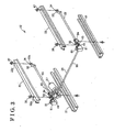
- Fig. 2 is a side view illustrating a power seat slide apparatus according to the first embodiment
- Fig. 3 is an exploded perspective view illustrating the power seat slide apparatus according to the first embodiment
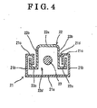
- Fig. 4 is a cross sectional view, illustrating the power seat slide apparatus according to the first embodiment, taken along line IV-IV in Fig. 2 ;
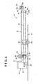
- Fig. 5 is a longitudinal cross sectional view, illustrating the power seat slide apparatus according to the first embodiment, taken along a longitudinal direction of an upper rail and a lower rail of the power seat slide apparatus;
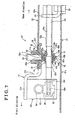
- Fig. 6 is a longitudinal cross sectional view, illustrating the power seat slide apparatus according to the first embodiment, taken along an axial direction of a screw shaft of the power seat slide apparatus;
- Fig. 7 is an enlarged cross sectional view of Fig. 6 .
- Fig. 8 is an enlarged cross sectional view partially illustrating the power seat slide apparatus according to the second embodiment
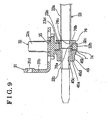
- Fig. 9 is an enlarged cross sectional view partially illustrating the power seat slide apparatus according to the third embodiment.
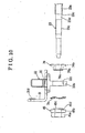
- Fig. 10 is an exploded front view partially illustrating the power seat slide apparatus according to the third embodiment
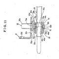
- Fig. 11 is an enlarged cross sectional view partially illustrating the power seat slide apparatus according to the fourth embodiment.
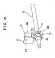
- Fig. 12 is an enlarged perspective view partially illustrating the power seat slide apparatus according to the fourth embodiment.
- Fig. 13 is an exploded cross sectional view partially illustrating the power seat slide apparatus according to the fourth embodiment
- Fig. 14 is an enlarged cross sectional view partially illustrating the power seat slide apparatus according to the fifth embodiment.
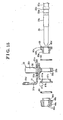
- Fig. 15 is an exploded cross sectional view partially illustrating the power seat slide apparatus according to the fifth embodiment.
- the seat 10 which is mounted to a vehicle floor 11, includes a power seat slide apparatus 12 of which structure will be described below in detail.
- the seat 10 further includes a seat cushion 13, which structures a seating surface, and a seatback 14, which structures a back-supporting surface.
- the seatback 14 is assembled onto a rear end portion of the seat cushion 13 so as to be pivotable in the forward and backward direction relative to the seat cushion 13 and to be fixedly supported at a set recline angle position via a known reclining apparatus.
- the power seat slide apparatus 12 mainly includes left and right lower rails 21, left and right upper rails 22, left and right screw shafts 23, left and right feeding nuts 24 and a driving unit 25.
- left and right lower rails 21, left and right upper rails 22, left and right screw shafts 23, left and right feeding nuts 24 and a driving unit 25 mainly includes left and right lower rails 21, left and right upper rails 22, left and right screw shafts 23, left and right feeding nuts 24 and a driving unit 25.
- left side components are described as an example of each of the left and right side components unless otherwise indicated.
- the lower rail 21 (serving as a fixture member) is an elongated member extending in the forward and backward direction of the seat 10.
- the left and right lower rails 21 are adapted to be disposed on the vehicle floor 11 so as to be parallel with each other in the width direction of the seat 10.
- the lower rail 21 includes a bottom wall 21a, a pair of side walls 21b (left and right side walls), and a pair offlange walls 21c (left and right flange walls).
- the left and right side walls 21b upwardly extend from left and right end portions of the bottom wall 21a, respectively.
- the lower rail 21 is formed to have an approximately U-shaped cross section. Front and rear end portions of the lower rail 21 are adapted to be connected to the vehicle floor 11 by means of connecting members, such as bolts, thereby fixing the lower rail 21 to the vehicle floor 11.
- the upper rail 22 (serving as a movable member) is an elongated member extending in the forward and backward direction of the seat 10.
- the left and right upper rails 22 are adapted to be assembled onto the left and right lower rails 21, respectively, so as to be parallel with each other.
- the upper rail 22 includes an upper wall 22a, a pair of side walls 22b (left and right side walls) and a pair of flange walls 22c (left and right flange walls).
- the left and right side walls 22b downwardly extend from left and right end portions of the upper wall 22a, respectively.
- the upper rail 22 is formed to have an approximately inverted U-shaped cross section.
- the left and right side walls 22b of the upper rail 22 are slidably engaged with the left and right side walls 21b of the lower rail 21, respectively.
- Front and rear end portions of the upper rail 22 are adapted to be connected to the seat cushion 13 via brackets 27 (see Fig. 2 ), respectively, thereby fixing the upper rail 22 to the seat cushion 13.
- the screw shaft 23 is provided between the lower rail 21 and the upper rail 22 so as to extend in the forward and backward direction of the seat 10.
- an axial direction of the screw shaft 23 corresponds to the forward and backward direction of the seat 10.
- the screw shaft 23 includes an external thread portion 23p at an outer circumferential surface thereof.
- the external thread portion 23p includes a rear screw portion (a lead screw) 23a, a partial screw portion 23b (incomplete screw portion) and a front screw portion 23c.
- the rear screw portion 23a is formed at a rear side portion of the external thread portion 23p and is threaded in a first rotational direction.
- the partial screw portion 23b is formed at a portion being further forward than the rear screw portion 23a.
- the front screw portion 23c is formed at a portion being further forward than the partial screw portion 23b and is threaded in a second rotational direction (in an inverse direction of the first rotational direction).
- the rear screw portion 23 a and the front screw portion 23c may be threaded in the same direction with each other.
- the rear screw portion 23a of the screw shaft 23 serves as a feeding screw portion.
- a fixing nut 43 is fixedly connected to the partial screw portion 23b of the screw shaft 23.
- the front screw portion 23c of the screw shaft 23 serves as a connecting screw portion. More specifically, a connecting nut 44 (described below) is fixedly connected to the front screw portion 23c. Further, the front screw portion 23c is supported by a bearing hole 32c of a bolt 32 via an intermediate member 7 along with the fixing nut 43.
- the front end portion and a rear end portion of the screw shaft 23 are supported by the upper rail 22 so as to be rotatable only. Accordingly, when the screw shaft 23 is operated to rotate, the upper rail 22 slides on the lower rail 21 in the forward and backward direction of the seat 10 along with the screw shaft 23.
- a structure of the driving unit 25 and a structure for supporting the screw shaft 23 to the upper rail 22 will be described in detail.
- a front supporting bracket (serving as a supporting member) 31 is connected to the front end portion of the upper rail 22 by means of the bolt 23. Further, a rear supporting bracket 33 is connected to the rear end portion of the upper rail 22 by means of a bolt 34.
- the front supporting bracket 31 is made from a plate member. As illustrated in Fig. 6 , a bolt hole 35 is defined at a central portion of the front supporting bracket 31. An extending portion 32a of the bolt 32 is inserted through the bolt hole 35. Further, a positioning protrusion 36 is formed at a rear end portion of the front supporting bracket 31. On the other hand, a bolt hole 22e and a positioning hole 22f are formed at a front end portion of the upper wall 22a of the upper rail 22, onto which the front supporting bracket 31 is assembled. The extending portion 32a of the bolt 32 is inserted through the bolt hole 22e of the upper rail 22. Further, the positioning protrusion 36 of the front supporting bracket 31 fits into the positioning hole 22f of the upper rail 22.
- the extending portion 32a of the bolt 32 is inserted through the bolt hole 35 of the front supporting bracket 31 and the bolt hole 22e of the upper rail 22 in a condition where the positioning protrusion 36 of the front supporting bracket 31 fits into the positioning hole 22f of the upper rail 22. Then, a nut 39 is screwed onto the extending portion 32a of the bolt 32. Thus, the front supporting bracket 31 is fixed to the upper rail 22.
- a supporting portion 32b is formed at a lower portion of the bolt 32 so as to protrude therefrom.
- the supporting portion 32b is fixedly connected to the front supporting bracket 31 so as to be integral therewith.
- the supporting portion 32b (the bolt 32) structures a part of the front supporting bracket 31.
- the supporting portion 32b may be integrally formed at the front supporting bracket 31.
- the supporting portion 32b is disposed between the front supporting bracket 31 and the lower rail 21.
- the bearing hole 32c is formed at the supporting portion 32b of the bolt 32.
- a diameter of the bearing hole 32c is arranged to be slightly larger than a diameter of the screw shaft 23.
- the screw shaft 23 is inserted through the bearing hole 32c formed at the bolt 32 via the intermediate member 7. More specifically, the intermediate member 7 is provided at a clearance defined between the screw shaft 23 and an inner circumferential wall of the bearing hole 32c formed at the supporting portion 32b of the bolt 32.
- the fixing nut (serving as a thrust receiving member) 43 is provided at a rear side of the supporting portion 32b of the bolt 32 in the axial direction (serving as a thrust direction), while the connecting nut 44 is provided at a front side of the supporting portion 32b. More specifically, the fixing nut 43 and the connecting nut 44 are disposed in the axial direction of the screw shaft 23 so as to face each other, while the bolt 32 fixedly connected to the supporting bracket 31 is disposed between the fixing nut 43 and the connecting nut 44.
- a flange nut is employed as the fixing nut 43, for example.
- the fixing nut 43 includes an extending portion 43a, a flange portion 43b and an internal thread portion 43c.
- the extending portion 43a of the fixing nut 43 extends in the axial direction of the screw shaft 23.
- the flange portion 43b is formed at a front side of the extending portion 43a and is disposed at a rear side of the supporting portion 32b of the bolt 32.
- a diameter of the flange portion 43b is formed to be larger than a diameter of the extending portion 43a.
- the inner thread portion 43c is sequentially formed through the extending portion 43a and the flange portion 43b in the axial direction of the screw shaft 23.
- the fixing nut 43 is fixedly tightened to a raising portion 23n formed at the partial screw portion 23b of the screw shaft 23 through the internal thread portion 43c.
- the flange portion 43b of the fixing nut 43 elastically presses an elastic protruding collar portion 71b of the intermediate member 7 towards a rear end surface of the supporting portion 32b.
- a flange nut is employed as the connecting nut 44, for example.
- the connecting nut 44 includes an extending portion 44a, a flange portion 44b and an internal thread portion 44c.
- the extending portion 44a extends in the axial direction of the screw shaft 23.
- the flange portion 44b is formed at a rear side of the extending portion 44a and is disposed at a front side of the supporting portion 32b of the bolt 32.
- a diameter of the flange portion 44b is formed to be larger than a diameter of the extending portion 44a.
- the internal thread portion 44c is sequentially formed through the extending portion 44a and the flange portion 44b in the axial direction of the screw shaft 23.
- the connecting nut 44 is screwed onto the front screw portion 23c of the screw shaft 23 through the internal thread portion 44c.
- the intermediate member 7 is provided between the supporting portion 32b of the bolt 32 and the screw shaft 23 and between the fixing nut 43 and the connecting nut 44. More specifically, the intermediate member 7 is structured with a bush 71 and a plane washer 72, which have a high sliding ability.
- the bush 71 is made from a resin material or a metallic material, for example.
- the bush 71 includes a cylindrical portion 71a, which has a shaft bore, and the elastic protruding collar portion (serving as an elastic thrust portion) 71b, which is formed at a rear end of the cylindrical portion 71a.
- the cylindrical portion 71a is formed in a cylindrical shape extending in the axial direction of the screw shaft 23. Further, the cylindrical portion 71a is disposed inside the bearing hole 32c formed at the bolt 32.
- the screw shaft 23 is inserted through the shaft bore of the cylindrical portion 71a of the intermediate member 7.
- An inner circumferential surface of the cylindrical portion 71a is compressed to contact the external thread portion 23p formed at the outer circumferential surface of the screw shaft 23.
- An external circumferential surface of the cylindrical portion 71a (serving as a radial sliding contact surface) slidably and rotatably fits the inner circumferential surface of the bearing hole 32c (serving as a radial bearing surface).
- the elastic protruding collar portion 71b structures the elastic thrust portion of the intermediate member 7.
- the elastic protruding collar portion 71b extends radially outwardly and slightly inclines, from a radially inward portion to a radially outward portion thereof, in the axially backward direction of the screw shaft 23.
- the elastic protruding collar portion 71b of the sliding contact portion 71 includes a form of a disc spring which is elastically deformable in the axial direction of the screw shaft 23.
- the elastic protruding collar portion 71b is disposed between the supporting portion 32b of the bolt 32 and the flange portion 43b of the fixing nut 43.
- a front end surface of the elastic protruding collar portion 71b (serving as a first thrust sliding contact surface) elastically contacts a rear end surface of the supporting portion 32b (serving as a first/second thrust bearing surface) of the bolt 32.
- a rear end surface of the elastic protruding collar portion 71b elastically contacts a front end surface of the flange portion 43b.
- the elastic protruding collar portion 71b is an elastic member, which is elastically deformed in the axial direction of the screw shaft 23 when the elastic protruding collar portion 71b is pressed in the axially forward direction of the screw shaft 23 by the flange portion 43b of the fixing nut 43.
- the plane washer (serving as a thrust portion) 72 of the intermediate member 7 is made from a metallic material, for example.
- the plane washer 72 includes a shaft hole at a central portion thereof. Further, an outer diameter, of the plane washer 72 is formed to be equal to or slightly smaller than a diameter of the elastic protruding collar portion 71b of the bush 71. Further, the plane washer 72 is formed sequentially in a circumferential direction thereof, i.e., formed in a disc-shape. According to the first embodiment, the plane washer 72 is hardly elastically deformed in the axial direction of the screw shaft 23. An inner circumferential surface forming the shaft hole of the plane washer 72 contacts an outer circumferential surface of a front end portion of the cylindrical portion 71a of the bush 71.
- the plane washer 72 is disposed between the supporting portion 32b of the bolt 32 and the flange portion 44b of the connecting nut 44. Further, the plane washer 72 is supported by a rear end surface of the flange portion 44b by being in contact therewith, so that the flange portion 44b slidably contacts the front end surface of the supporting portion 32b of the bolt 32. In other words, a rear end surface of the plane washer 72 (serving as a second thrust sliding contact surface) slidably contacts the front end surface of the supporting portion 32b (serving as a second thrust bearing portion) of the bolt 32.
- the elastic protruding collar portion 71b of the bush 71 and the connecting nut 44 structure an elastic biasing mechanism.
- the connecting nut 44 is connected to the front screw portion 23c of the screw shaft 23. Accordingly, the elastic protruding collar portion 71b of the bush 71 is elastically deformed so that the front end surface of the elastic protruding collar portion 71b elastically contacts the rear end surface of the supporting portion 32b of the bolt 32, and the rear end surface of the elastic protruding collar portion 71b elastically contacts the front end surface of the flange portion 43b of the fixing nut 43.
- the intermediate member 7 is axially elastically biased towards the fixing nut 43. Accordingly, the intermediate member 7 and the fixing nut 43 are assembled onto the screw shaft 23 without a clearance between the intermediate member 7 and the fixing nut 43.
- a front end of the front supporting bracket 31 is bent upwardly at the front portion of the upper rail 22, thereby forming a vertical bent portion 31b. Further, an end portion (an upper end) of the vertical bent portion 31b is bent approximately vertically in the front direction, thereby forming a horizontal supporting portion 31c extending horizontally in the front direction.
- a gear box 51 is fixedly connected to a lower surface of the horizontal supporting portion 31 by means of an appropriate connecting member, such as a bolt, for example.
- the rear supporting bracket 33 is formed in an L-shape so as to have a horizontal portion 33a and a vertical portion 33b. Further, a bolt hole 33c is formed at the horizontal portion 33a, so that a bolt 34 is inserted through the bolt hole 33c. On the other hand, a bolt hole 22g is formed at a rear end portion of the upper rail 22, at which the rear supporting bracket 33 is assembled, so that the bolt 34 is also inserted through the bolt hole 22g formed at the upper rail 22.
- the bolt 34 is inserted through the bolt hole 33c of the rear supporting bracket 33 and the bolt hole 22g of the upper rail 22, and a nut 47 is screwed onto the bolt 34, thereby integrally assembling the rear supporting bracket 33 onto the upper rail 22.
- a through hole 48 is formed at the vertical portion 33b of the rear supporting bracket 33, so that the screw shaft 23 is inserted through the through hole 48.
- a bush 79 is assembled onto the through hole 48.
- a cross sectional shape of the bush 79 includes a substantially U-shape.
- a rear shaft end portion of the screw shaft 23 is rotatably supported by the bush 79. Accordingly, the screw shaft 23, to which the feeding nut 24 is screwed, is rotatably supported by the bush 71 provided at the front end portion of the screw shaft 23 and by the bush 79 provided at the rear end portion of the screw shaft 23.
- the gear box 51 which is fixedly connected to the lower surface of the front end portion (the horizontal portion 31a) of the front supporting bracket 31, includes a housing 52. As illustrated in Fig. 7 , a worm wheel 53 (an output rotational portion) is rotatably supported by the housing 52 so as to be coaxial with the screw shaft 23.
- a spline hole 53a is formed at a rotational center of the worm wheel 53, while a spline engagement portion 23r is formed at the front end portion of the screw shaft 23.
- the spline engagement portion 23r of the screw shaft 23 and the spline hole 53a of the worm wheel 53 are engaged with each other. Further, a worm formed at a worm shaft 54 is engaged with the worm wheel 53.
- the worm shaft 54 is supported by the housing 52 so as to be rotatable about a rotational axis which is orthogonal to a rotational axis of the worm wheel 53, i.e., so as to be rotatable about a horizontal axis which is orthogonal to the forward and backward direction of the vehicle.
- the worm wheel 53 and the worm shaft 54 structure a reduction gear mechanism.
- a rotation transmitting shaft 55 extending in the lateral direction of the seat 10 is disposed between the left and right gear boxes 51.
- One end of the rotation transmitting shaft 55 is connected to the left worm shaft 54 supported by the left gear box 51, while another end of the rotation transmitting shaft 55 is connected to the right worm shaft 54 supported by the right gear box 51.
- An output shaft of a motor 57 is rotatably connected to the rotation transmitting shaft 55 via a gear mechanism. A rotation of the motor 57 is transmitted to the left and right worm shafts 54 via the rotation transmitting shaft 55.
- the worm wheel 53 rotates by a rotation of the worm shaft 54, so that the rotation of the motor 57 is reduced by the worm formed at the worm shaft 54 and the worm wheel 53. Further, the rotation of the worm wheel 53 is transmitted to the screw shaft 23 which is spline-engaged with the worm wheel 53. Accordingly, the left and right screw shafts 23 are operated to synchronously rotate, thereby slidably moving the left and right upper rails 22, in which the left and right screw shafts 23 are supported respectively, relative to the corresponding left and right lower rails 22.
- the motor 57, the rotation transmitting shaft 55 and the reduction gear mechanism (the worm shaft 54 and the worm wheel 53) structure the driving unit 25.
- the fixing nut 43 When relatively rotatably assembling the screw shaft 23 onto the bolt 32, first, the fixing nut 43 is screwed onto the screw shaft 23 from the rear side of the screw shaft 23 to the partial screw portion 23b.
- the internal thread portion 43c of the fixing nut 43 is plastically deformed at the raising portion 23n formed at a rear side of the front screw portion 23c of the partial thread portion 23b. Accordingly, the fixing nut 43 is firmly fixed to the screw shaft 23.
- the screw shaft 23 is inserted through the shaft bore formed at the bush 71 from a front portion of the screw shaft 23, and the elastic protruding collar portion 71b of the bush 71 is arranged to elastically contact the front end surface of the flange portion 43b of the fixing nut 43.
- the bush 71 and the screw shaft 23 are inserted through the bearing hole 32c of the bolt 32 from the front portion of the screw shaft 23, and the outer circumferential surface of the cylindrical portion 71a of the bush 71 is arranged to contact the supporting portion 32b of the bolt 32.
- the rear end surface of the supporting portion 32b is arranged to slidably contact the elastic protruding collar portion 71b of the bush 71.
- the plane washer 72 is assembled onto the screw shaft 23 from the front side of the screw shaft 23 and the bush 71 so that the screw shaft 23 is inserted through the shaft bore of the plane washer 72.
- the rear end surface of the plane washer 72 is arranged to slidably contact the front end surface of the supporting portion 32b of the bolt 32.
- the connecting nut 44 is screwed onto the front screw portion 23c of the screw shaft 23 from the front side of the screw shaft 23 and is tightened thereat.
- the connecting nut 44 is tightened in a condition where the elastic protruding collar portion 71b of the bush 71 is axially elastically deformed with a tightening torque with which the connecting nut 44 is prevented from loosening even when the screw shaft 23 is driven to rotate, i.e., with a tightening torque being larger than a rotational torque of the screw shaft 23.
- the flange portion 44b of the connecting nut 44 presses the front end surface of the cylindrical portion 71a of the bush 71, and the elastic protruding collar portion 71b is accordingly elastically deformed in the axial direction of the screw shaft 23 so as to elastically contact the flange portion 43b of the fixing nut 43.
- the screw shaft 23 and the bolt 32 are assembled so that the screw shaft 23 is rotatable relative to the bolt 32.
- the left and right worm wheels 53 (each serving as an output rotational member) are operated to rotate by the rotation of the corresponding left and right worm shafts 54.
- the rotation of each worm wheel 53 is transmitted to the corresponding screw shaft 23 via the spline engagement portion 23r formed at the screw shaft 23.
- the screw shaft 23 is operated to rotate by the rotation transmitting shaft 55 driven by the motor 57 via the reduction gear mechanism structured with the worm shaft 54 and the worm wheel 53.
- the screw shaft 23 rotates to move in the axial direction relative to the feeding nut 24. Accordingly, the upper rail 22 is operated to move in the forward direction or in the backward direction via the front supporting bracket 31 and the rear supporting bracket 33, which rotatably supports the screw shaft 23, thereby adjusting a longitudinal position of the vehicle seat 10.
- the intermediate member 7 structured with the bush 71 and the plane washer 72 is disposed between the screw shaft 23 and the supporting portion 32b of the bolt 32 which is provided integrally with the front supporting bracket 31.
- the bush 71 and the plane washer 72 are supported by the screw shaft 23 so as to be slidably rotatable relative to the supporting portion 32b of the bolt 32.
- the outer circumferential surface of the cylindrical portion 71a of the bush 71 slidably contacts the inner circumferential surface of the bearing hole 32c formed at the supporting portion 32b, and the rear end surface of the elastic protruding collar portion 71b of the bush 71 slidably contacts the front end surface of the fixing nut 43.
- the front end surface of the plane washer 72 slidably contacts the rear end surface of the connecting nut 44. Accordingly, the intermediate member 7 structured with the bush 71 and the plane washer 72 smoothly slidably rotates relative to the supporting portion 32b of the bolt 32.
- the front end surface of the elastic protruding collar portion 71b of the bush 71 elastically contacts the rear end surface of the supporting portion 32b of the bolt 32 by the elastic force of the elastic protruding collar portion 71b.
- the rear end surface of the elastic protruding collar portion 71b elastically contacts the fixing nut 43 provided at the screw shaft 23
- the front end surface of the elastic protruding collar portion 71b is elastically pressed in the axial direction to the rear end surface of the supporting portion 32b of the bolt 32.
- the bush 71 and the fixing nut 43 are provided on the screw shaft 23 without a clearance between the elastic protruding collar portion 71b of the bush 71 and the fixing nut 43, thereby tolerating a dimensional error, an assembling error, and the like, between the screw shaft 23 and the fixing nut 43.
- the bush 71 smoothly slidably rotates relative to the supporting portion 32b of the bolt 32, and errors such as the dimensional error and the assembling error between the fixing nut 43 and the connecting nut 44, which are fixedly connected to the screw shaft 23, are tolerated by an elastic force acting in the axial direction of the screw shaft 23. Accordingly, the screw shaft 23 smoothly rotates relative to the supporting portion 32b of the bolt 32.
- the outer circumferential surface of the cylindrical portion 71a of the bush 71 is slidably supported relative to the bolt 32.
- the screw shaft 23 is stably supported by the outer circumferential surface of the cylindrical portion 71a of the bush 71.
- the intermediate member 7 is provided between the supporting portion 32b of the bolt 32 and the screw shaft 23 and between the fixing nut 43 and the connecting nut 44. Accordingly, the intermediate member 7 is stably supported by the bolt 32, the fixing nut 34 and the connecting nut 44 so as to allow the screw shaft 23 to smoothly rotate.
- the connecting nut 44 is tightened to the screw shaft 23 in the condition where the elastic protruding collar portion 71b of the bush 71 is axially elastically deformed with the tightening torque with which the connecting nut 44 is prevented from loosening even when the screw shaft 23 is driven to rotate, i.e., with the tightening torque being larger than the rotational torque of the screw shaft 23. Accordingly, the connecting nut 44 is surely fixed to the screw shaft 23 so as not to loosen.
- the fixing nut 43 and the connecting nut 44 are connected to the partial screw portion 23b and the front screw portion 23c of the screw shaft 23, respectively. Accordingly, the fixing nut 43 and the connecting nut 44 are fixedly connected to the screw shaft 23 without executing a compressing process, in which end portions of nuts are compressed to connect the nuts onto the screw shaft 23 in a condition where the nuts are screwed onto the screw shaft 23 as in the conventional manner. Therefore, the screw shaft 23 does not receive a large load to be generated due to such compressing process. Thus, the screw shaft 23 is prevented from deforming and is allowed to rotate smoothly.
- the elastic protruding collar portion 71b of the bush 71 which is an elastic deformable member, is provided at the axially rear side of the supporting portion 32b of the bolt 32.
- such elastic deformable member such as an elastic washer may be also provided at the axially front side of the bolt 32, i.e., the elastic deformable members may be provided at both front and rear sides of the bolt 32, respectively.
- any washer such as a wave washer, a cone disc washer, a plastic washer, a rubber washer, an elastic foam washer, a spring washer, or the like, may be employed as such elastic washer as long as it is elastically deformable in the axial direction of the screw shaft 23.
- the dimensional error between the supporting portion 32b and the connecting nut 44 may be effectively tolerated by the elasticity of the elastic washer in the axial direction, and the screw shaft 23 may be operated to smoothly rotate relative to the supporting portion 32b.
- the intermediate member 7 includes a cylindrical collar portion (serving as a radial portion) 73 and an elastic washer (serving as the elastic thrust portion) 74 in place of the bush 71.
- the cylindrical collar portion 73 does not include a radial protruding portion such as the protruding collar portion of the elastic protruding collar portion 71b according to the first embodiment.
- the cylindrical collar portion 73 and the elastic washer 74 have high sliding ability.
- the cylindrical collar portion 73 may be made from a metallic material or a resin material, for example.
- any washer such as a wave washer, a cone-disc washer, a spring washer, a rubber washer, a plastic washer, a foam washer, or the like, may be employed as the elastic washer 74 as long as it is elastically deformable in the axial direction of the screw shaft 23.
- the cylindrical collar portion 73 fits the front screw portion 23c of the screw shaft 23.
- An outer circumferential surface of the cylindrical collar portion 73 (serving as the radial sliding contact surface) slidably contacts the inner circumferential surface of the bearing shalt 32c formed at the supporting portion 32b of the bolt 32.
- the elastic washer 74 is formed in an annular shape so that a radially outer portion and a radially inner portion thereof are elastically deformable in the axial direction of the screw shaft 23.
- a front end surface of the elastic washer 74 (serving as the first/second thrust sliding contact surface) slidably contacts the rear end surface of the supporting portion 32b of the bolt 32.
- the plane washer (serving as the thrust portion) 72 is provided between the front end surface of the supporting portion 32b of the bolt 32 and the rear end surface of the connecting nut 44.
- the rear end surface of the plane washer 72 (serving as the first/second thrust sliding contact surface) slidably contacts the front end surface of the supporting portion 32b of the bolt 32.
- the elastic washer 74 and the connecting nut 44 structure the elastic biasing mechanism. More specifically, because the connecting nut 44 is connected to the front screw portion 23c of the screw shaft 23 by being tightened thereto so as to elastically deform the elastic washer 74, the elastic washer 74 is elastically biased towards the rear end surface of the supporting portion 32b of the bolt 32, and the elastic washer 74 and the cylindrical collar portion 73 are elastically pressed to the fixing nut 43. Accordingly, errors such as the dimensional error and the assembling error between the screw shaft 23 and the fixing nut 43 are tolerated.
- the intermediate member 7 elastically deforms in the axial direction, the dimensional error between the fixing nut 43 and the connecting nut 44 is tolerated. Accordingly, the screw shaft 23 is allowed to smoothly rotate relative to the front supporting bracket 31.
- the intermediate member 7 is structured with a sliding contact bush (serving as the thrust receiving member) 76 and the elastic washer (serving as the elastic thrust member) 74 which functions as the elastic member.
- a fixing nut such as the fixing nut 43 employed in the first embodiment, is not provided.
- the sliding contact bush 76 is pressed to a step portion 23e, which protrudes from the screw shaft 23, so as to be fixed thereto by a connecting nut 46.
- the front screw portion 23c, a fitting portion (serving as an unthreaded portion) 23d, the step portion 23e and the rear screw portion 23a are formed at the outer circumferential surface of the screw shaft 23 in the mentioned order from the front end portion of the screw shaft 23.
- the front screw portion 23c functions as a connecting screw portion for fixedly connecting the connecting nut 46 thereon.
- the fitting portion 23d fits the sliding contact bush 76.
- the step portion (collar portion) 23e contacts a rear end surface of the sliding contact bush 76.
- the feeding nut 24 is screwed onto the rear screw portion 23a. An outer circumferential surface of the fitting portion 23d of the screw shaft 23 is not threaded.
- the sliding contact bush 76 which is made from a metallic material, structures the intermediate member 7. More specifically, the sliding contact bush 76 includes an extending portion 76a, a flange portion 76b and a shaft bore 76c.
- the extending portion 76a extends in the axial direction of the screw shaft 23.
- the flange portion 76b is formed at a rear side of the extending portion 76a and is disposed at the rear side of the supporting portion 32b of the bolt 32.
- a diameter of the flange portion 76b is larger than a diameter of the extending portion 76a.
- the shaft bore 76c is sequentially formed through the extending portion 76a and the flange portion 76b in the axial direction of the screw shaft 23.
- the fitting portion 23d of the screw shaft 23 is inserted through the shaft bore 76c of the sliding contact bush 76.
- An inner circumferential surface of the shaft bore 76c is not threaded.
- the extending portion 76a of the sliding contact bush 76 serves as the radial portion.
- An outer circumferential surface of the extending portion 76a (serving as the radial sliding contact surface) slidably contacts the inner circumferential surface of the bearing hole 32c (serving as the radial bearing surface) formed at the supporting portion 32b_of the bolt 32.
- the extending portion 76a of the sliding contact bush 76 is rotatably supported by the supporting portion 32b.
- a rear opening rim portion of the shaft bore 76c of the sliding contact bush 76 is engaged with the step portion 23e of the screw shaft 23.
- the rear opening rim portion of the shaft bore 76c structures a contact portion (collar contact portion), which contacts the step portion 23e of the screw shaft 23.
- the flange portion 76b of the sliding contact bush 76 serves as the thrust portion.
- a front end surface of the flange portion 76b (serving as the first/second thrust sliding contact surface) slidably contacts the rear end surface of the supporting portion 32b (serving as the frst/second thrust bearing surface) of the bolt 32.
- the connecting nut 46 is provided at the front side of the bolt 32 so as to be opposite from the sliding contact bush 76 relative to the bolt 32.
- the connecting nut 46 includes an extending portion 46a, a flange portion 46b, a protruding end portion 46d and an internal thread portion 46c.
- the extending portion 46a extends in the axial direction of the screw shaft 23.
- the flange portion 46b is formed at a rear side of the extending portion 46a and is disposed at the front side of the supporting portion 32b of the bolt 32.
- a diameter of the flange portion 46b is arranged to be larger than a diameter of the extending portion 46a.
- the protruding end portion 46d extends from a rear end portion of the flange portion 46b.
- a diameter of the protruding end portion 46d is formed to be smaller than the diameter of the flange portion 46b.
- the internal thread portion 46c is formed sequentially through the extending portion 46a, the flange portion 46b and the protruding end portion 46d. in the axial direction of the screw shaft 23.
- the front screw portion 23c of the screw shaft 23 is inserted through the thread portion 46c, so that the thread potion 46c is screwed onto the front screw portion 23c.
- An outer circumferential surface of the protruding end portion 46d slidably contacts a part of the inner circumferential portion of the shaft bore 32c of the bolt 32.
- the connecting nut 46 and the step portion 23e formed at the screw shaft 23 structure first and second collar portions provided at the screw shaft 23.
- the elastic washer (serving as the elastic thrust portion) 74 structuring the intermediate member 7 is provided between the flange portion 46b of the connecting nut 46 and the supporting portion 32b of the bolt 32 at an outer circumferential surface of the protruding end portion 46d of the connecting nut 46.
- the same elastic washer according to the second embodiment may be employed as the elastic washer 74 as an example.
- a rear end surface of the elastic washer 74 (serving as the first/second thrust sliding contact surface) elastically contacts the front end surface of the supporting portion 32b (serving as the first/second thrust bearing surface) of the bolt 32 by the elastic force of the elastic washer 74. Further, because the front end surface of the elastic washer 74 contacts the connecting nut 46 tightened to the screw shaft 23, the rear end surface of the elastic washer 74 is elastically pressed to the front end surface of the supporting portion 32b in the axial direction of the screw shaft 23.
- the elastic washer 74 and the connecting nut 46 structure the elastic biasing mechanism.
- the connecting nut 46 is tightened to the front screw portion (serving as the connecting screw portion) 23c of the screw shaft 23 and the elastic washer 74 is accordingly elastically deformed.
- the front end surface of the flange portion 76b formed at the sliding contact bush 76 and the rear end surface of the elastic washer 74 are arranged to elastically contact the rear and front end surfaces of the supporting portion 32b of the bolt 32, respectively, and the elastic washer 74 is elastically biased to the sliding contact bush 76.
- errors such as the dimensional error and the assembling error between the screw shaft 23 and the sliding contact bush 76 are tolerated.
- the bolt 32 is fixed to the front supporting bracket 31 of which a cross sectional shape is formed in an L-shape.
- a front end portion of the front supporting bracket 31 is bent vertically upwardly, thereby forming the vertical bent portion 31b.
- a fixing hole 31d is formed at the vertical bent portion 31b.
- a connecting member for fixing the gear box 51 is inserted into the fixing bore 31d of the front supporting bracket 31.
- the upper rail 22 is fixed to an upper rim surface portion of the bolt hole 35 formed at the front supporting bracket 31 by being interposed between the front supporting bracket 31 and a connecting member such as a nut.
- the sliding contact bush 76 when assembling the sliding contact bush 76, the connecting nut 46 and the bolt 32 onto the screw shaft 23, first, the sliding contact bush 76 is assembled onto the screw shaft 23 from the front side of the screw shaft 23 so that the screw shaft 23 penetrates through the sliding contact bush 76, and the rear opening rim portion of the shaft bore 76c formed at the sliding contact bush 76 is arranged to contact the step portion 23e formed at the screw shaft 23.
- the sliding contact bush 76 is supported by an engagement between the shaft bore 76c and the fitting portion 23d of the screw shaft 23.
- the extending portion 76a of the contact bush 76 supported by the screw shaft 23 is inserted into the bearing hole 32c formed at the bolt 32.
- the elastic washer 74 is assembled onto the screw shaft 23 from the front side thereof so that the screw shaft 23 penetrates through the elastic washer 74. Furthermore, the connecting nut 46 is screwed onto the screw shaft 23 from the front side thereof and is tightened to the front screw portion 23c of the screw shaft 23, so that the rear end surface of the protruding end portion 46d of the connecting nut 46 is arranged to adjoin the front end surface of the extending portion 76a of the sliding contact bush 76.
- the connecting nut 46 is tightened in a condition where the elastic washer 74 is axially elastically deformed with the tightening torque with which the connecting nut 46 is prevented from loosening even when the screw shaft 23 is driven to rotate, i.e., with the tightening torque being larger than the rotational torque of the screw shaft 23. Accordingly, the elastic washer 74 is axially compressed and is accordingly elastically deformed in the axial direction of the screw shaft 23, and the rear end surface of the flange portion 46b of the connecting nut 46 is arranged to slidably and elastically contact the front end surface of the supporting portion 32b of the bolt 32.
- the rear opening rim portion of the extending portion 76a of the sliding contact bush 76 is pressed in the axial direction towards the step portion 23e formed at the screw shaft 23 by the tightening force of the connecting nut 46 applied in the axial direction of the screw shaft 23. Accordingly, the sliding contact bush 76 is arranged to surely fit the fitting portion 23d of the screw shaft 23 without dislocating in the axial direction of the screw shaft 23.
- the elastic washer 74 is provided between the front end surface of the supporting portion 32b of the bolt 32 and the flange portion 46b of the connecting nut 46. Still further, the rear end surface of the elastic washer 74 elastically contacts the front end surface of the supporting portion 32b of the bolt 32 by the elastic force of the elastic washer 74. Accordingly, the elastic washer 74 tolerates a dimensional error of the connecting nut 46, so that the screw shaft 23 is allowed to smoothly rotate relative to the supporting portion 32b of the bolt 32.
- an elastic bush 75 is provided between the supporting portion 32b of the bolt 32 and the connecting nut 46 as the elastic member in place of the elastic washer 74 according to the third embodiment, as illustrated in Figs. 11 to 13 .
- the elastic bush 75 is made from an elastic material, such as a soft resin material, a rubber material, or the like, for example.
- the elastic bush 75 includes a cylindrical portion (serving as the radial portion) 75a, a flange portion (serving as the elastic thrust portion) 75b and a hole portion 75c.
- the cylindrical portion 75a is provided between the inner circumferential surface of the bearing hole 32c of the bolt 32 and the outer circumferential surface of the protruding end portion 46d of the connecting nut 46.
- the flange portion 75b includes an elastic deformable portion formed at a front side of the cylindrical portion 75a so as to protrude therefrom in a radially outward direction thereof.
- a diameter of the flange portion 75b is arranged to be larger than a diameter of the cylindrical portion 75a.
- the hole portion 75c is formed sequentially through the cylindrical portion 75a and the flange portion 75b.
- the protruding end portion 46c of the connecting nut 46 is inserted into the hole portion 75c.
- a groove portion 75d is formed at a rear end surface of the flange portion 75b so as to sequentially extend in a circumferential direction thereof.
- the groove portion 75d may be formed partially in the circumferential direction of the flange portion 75b. Alternatively, plural recesses aligned in the circumferential direction of the flange portion 75b may be employed as the groove portion 75d.
- the flange portion 75b is easily elastically deformed in the axial direction of the screw shaft 23. Further, because the rear end surface of the flange portion 75b (serving as the first/second thrust sliding contact surface) elastically contacts the front end surface of the supporting portion 32b of the bolt 32, the rear end surface of the supporting portion 32b elastically contacts the front end surface of the flange portion 76b (serving as the first/second thrust sliding contact surface) of the sliding contact bush (serving as the thrust receiving member) 76.
- An outer circumferential surface of the cylindrical portion 75a (serving as the radial sliding contact surface) is relatively slidably and rotatably supported by the inner circumferential surface of the bearing hole 32c (serving as the radial bearing surface) formed at the supporting portion 32b of the bolt 32.
- the rear end surface of the connecting nut 46 is disposed in the vicinity of the front end surface of the sliding contact bush 76.
- the rear end surface of the cylindrical portion 75a of the elastic bush 75 elastically contacts the front end surface of the sliding contact bush 76 by the elastic force of the elastic bush 75 and elastically presses the contact portion (serving as a collar contact portion) of the sliding contact bush 76 to the step portion (collar portion) 23e formed at the screw shaft 23.
- the outer circumferential surface of the cylindrical portion 75a of the elastic bush 75 and the outer circumferential surface of the extending portion 76a of the sliding contact bush 76 are arranged to be coplanar so as to slidably contact the inner circumferential surface of the bearing hole 32c formed at the supporting portion 32b of the bolt 32.
- the sliding contact bush 76 is made from the metallic material, for example, and includes the extending portion 76a and the flange portion 76b in the same manner as the third embodiment.
- the outer circumferential surface of the extending portion 76a structures a radial sliding contact surface which is rotatably supported by the supporting portion 32b of the bolt 32.
- the flange portion 76b structures the thrust portion which is also rotatably supported by the supporting portion 32b of the bolt 32.
- the flange portion 75b of the elastic bush 75 and the connecting nut 44 structure the elastic biasing mechanism.
- the connecting nut 46 is screwed onto the front screw portion 23c of the screw shaft 23 and is tightened thereto, the flange portion 75b of the elastic bush 75 accordingly elastically deforms. Therefore, the front end surface of the flange portion 76b of the sliding contact bush 76 and the rear end surface of the flange portion 75b of the elastic bush 75 elastically contact the rear and front end surfaces of the supporting portion 32b, respectively, and the elastic bush 75 is elastically biased towards the sliding contact bush 76. Accordingly, the dimensional error, the assembling error, and the like, generated between the screw shaft 23 and the sliding contact bush 76 are tolerated.
- the rear end surface of the cylindrical portion 75a of the elastic bush 75 elastically contacts the front end surface of the sliding contact bush 76, and the contact portion of the sliding contact bush 76 is accordingly elastically pressed in the axial direction of the screw shaft 23 to the step portion 23e of the screw shaft 23. Therefore, the sliding contact bush 76 surely fits the fitting portion 23d of the screw shaft 23 without dislocating in the axial direction. Further, the sliding contact bush 76 and the elastic bush 75 allow the screw shaft 23 to smoothly rotate relative to the bolt 23.
- the flange portion 75b of the elastic bush 75 is provided between the font end surface of the supporting portion 32b of the bolt 32 and the flange portion 46b of the connecting nut 46, and the rear end surface of the flange portion 75b of the elastic bush 75 elastically contacts the front end surface of the supporting portion 32b of the bolt 32 by the elastic force of the elastic bush 75. Accordingly, the flange portion 75b tolerates the dimensional error of the connecting nut 46 more effectively than the elastic washer 74 according to the third embodiment. Thus, the screw shaft 23 is allowed to rotate further smoothly relative to the bolt 32.
- the connecting nut 46 is screwed onto the screw shaft 23 in a condition where the elastic bush 75 is elastically deformed in the axial direction with the tightening torque with which the connecting nut 46 is prevented from loosening even when the screw shaft 23 is driven to rotate, i.e., with the tightening torque being larger than the rotational torque of the screw shaft 23. Accordingly, the connecting nut 46 is surely fixed to the screw shaft 23 without loosening.
- Each of the elastic washer 74 according to the third embodiment and the elastic bush 75 according to the fourth embodiment is disposed at the front side of the supporting portion 32b of the bolt 32.
- the elastic washer 74 and the elastic bush 75 may be provided at the rear side of the supporting portion 32b of the bolt 32 in the corresponding embodiment.
- the front end surface of the elastic washer 74 elastically contacts the rear end surface of the supporting portion 32b of the bolt 32 by the elastic force of the elastic washer 74.
- the rear end surface of the elastic washer 74 contacts the front end surface of the flange portion 76b of the sliding contact bush 76.
- the front end surface of the elastic washer 74 is elastically pressed to the rear end surface of the supporting portion 32b of the bolt 32.
- the front end surface of the elastic bush 75 elastically contacts the rear end surface of the supporting portion 32b of the bolt 32 by the elastic force of the elastic bush 75.
- the rear end surface of the elastic bush 75 contacts the front end surface of the flange portion 76b of the sliding contact bush 76. Accordingly, the front end surfaces of the elastic bush 75 is elastically pressed to the rear end surface of the supporting portion 32b of the bolt 32.
- the power seat slide apparatus 12 includes an intermediate member 8 which is structured with a sliding contact member 80 and an annular elastic member 84.
- the sliding contact member 80 is arranged to slidably contact the supporting portion 32b of the bolt 32.
- the annular elastic member 84 having the elasticity serves as the elastic biasing mechanism.
- the sliding contact member 80 and the annular elastic member 84 are separately provided.
- the intermediate member 8 includes the sliding contact member 80, which is arranged to slidably contact the supporting portion 32b of the bolt 32, and the annular elastic member 84, which has the elasticity.
- the sliding contact member 80 is structured with a front sliding contact member 81, a rear sliding contact member 82 and the fitting member 83.
- the fitting member 83 which is made from a metallic material, includes an extending portion 83a, an intermediate portion 83b, a flange portion 83c and a shaft bore 83d.
- the extending portion 83a extends in the axial direction (the thrust direction) of the screw shaft 23.
- the intermediate portion 83b is formed at a rear side of the extending portion 83a.
- a diameter of the intermediate portion 83b is formed to be slightly larger than a diameter of the extending portion 83a.
- the flange portion 83c is formed at a rear side of the intermediate portion 83b and is disposed at the rear side of the supporting portion 32b of the bolt 32.
- a diameter of the flange portion 83c is formed to be larger than that of the intermediate portion 83b.
- the shaft bore 83d is sequentially formed through the extending portion 83a, the intermediate portion 83b and the flange portion 83c.
- the fitting portion 23d of the screw shaft 23 is inserted through the shaft bore 83d.
- the front sliding contact member 81 is provided between the outer circumferential surface of the extending portion 83a and the bearing hole 32c formed at the supporting portion 32b of the bolt 32.
- An outer circumferential surface of the intermediate portion 83b slidably contacts a rear portion of the inner circumferential surface of the bearing hole 32c of the bolt 32.
- the rear sliding contact member 82 is provided between a front end surface of the flange portion 83c and the rear end surface of the supporting portion 32b.
- a rear opening rim portion of the shaft bore 83d is engaged with the step portion 23e formed at the screw shaft 23.
- the rear sliding contact member 82 is a plane washer made from a metallic material, for example.
- the rear sliding contact member 82 is supported at the front end surface of the fitting member 83, so that a front end surface of the sliding contact member 82 (serving as the first/second thrust sliding contact surface) slidably contacts the rear end surface of the supporting portion 32b of the hole 32.
- the connecting nut 46 is provided at the front side of the bolt 32 so as to be opposite from the rear sliding contact member 82 relative to the bolt 32.
- the connecting nut 46 includes the extending portion 46a, the flange portion 46b, the internal thread portion 46c and the protruding end portion 46d.
- the connecting nut 46 structures a first collar portion provided at the screw shaft 23, while the step portion 23e formed at the screw shaft 23 structures a second collar portion provided at the screw shaft 23.
- the outer circumferential surface of the protruding end portion 46d of the connecting nut 46 and an outer circumferential surface of the intermediate portion 83b of the fitting member 83 of the sliding contact member 80 are arranged to be coplanar.
- the front sliding contact member (serving as a radial thrust member) 81 is made from a metallic material, for example.
- the front sliding contact portion 81 includes a cylindrical portion (serving as the radial portion) 81a, a flange portion (serving as the thrust portion) 81b and a hole portion 81d.
- the radial sliding contact surface is formed at a circumferential surface of the cylindrical portion 81a.
- the flange portion 81b radially outwardly protrudes from the cylindrical portion 81a so that a diameter of the flange portion 81b is formed to be larger than that of the cylindrical portion 81a.
- a thrust sliding contact surface (first/second thrust sliding contact surface) is formed at a rear end surface of the flange portion 81b.
- the hole potion 81d is sequentially formed through the cylindrical portion 81a and the flange portion 81b.
- the cylindrical portion 81a is provided along the outer circumferential surface of the protruding end portion 46b of the connecting nut 46 and an outer circumferential surface of the intermediate portion 83b of the fitting member 83.
- An outer circumferential surface of the cylindrical portion 81a (a surface being opposite from another surface facing the outer circumferential surfaces of the protruding end portion 46d of the connecting nut 46 and of the intermediate portion 83b of the fitting member 83) faces the inner circumferential surface of the bearing hole 32c formed at the supporting portion 32b of the bolt 32.
- the annular elastic member 84 is provided between a front end surface of the flange portion 81b and a rear end surface of the flange portion 46b of the connecting nut 46.
- the annular elastic member 84 which has the elasticity in the axial direction of the screw shaft 23 (the thrust direction), is formed in a ring shape while having a circular cross sectional shape and is made from an elastic material, such as a rubber material, silicone material, or the like.
- An annular supporting portion 81c is formed at an outer circumferential portion of the flange portion 81b.
- the annular supporting portion 81c is formed by bending an outer circumferential end portion of the flange portion 81b in the front direction for supporting an outer circumferential portion of the annular elastic member 84.
- the annular elastic member 84 is prevented from dislocating towards the outer circumferential side thereof i.e., in the radially outer direction.
- the annular elastic member 84 is supported between the flange portion 81b of the front sliding contact member 81 and the one of the connecting nut 46 and the fitting member 83, thereby greatly improving (extending) the useful life of the annular elastic member 84.
- the rear end surface of the flange portion 81b (serving as the first/second thrust sliding contact surface) of the front sliding contact member 81 is pressed to the front end surface of the supporting portion 32b of the bolt 32 by the elastic force of the annular elastic member 84. Accordingly, the supporting portion 32b presses the rear sliding contact member 82 to the flange portion 83b of the fitting member 83 by the rear end surface of the supporting portion 32b.
- the rear end surface of the connecting nut 46 is provided in the vicinity of the front end surface of the fitting member 83 while having a slight clearance therebetween:
- the connecting nut 46 elastically presses the fitting member 83 in the thrust direction to the step portion 23e of the screw shaft 23 by the connecting force (tightening force) applied to the front screw portion 23c of the screw shaft 23 and the elastic force of the annular elastic member 84.
- the annular elastic member 84 structures the elastic biasing mechanism. More specifically, the annular elastic member 84 is provided between the connecting nut 46 and the flange portion 81b of the front sliding contact member 81 for biasing the front sliding contact member 81 in the axial direction of the screw shaft 23 to the fitting member 83.
- the dimensional error, the assembling error, or the like, generated between the screw shaft 23 and the front sliding contact member 81 is tolerated by the annular elastic member 84. Accordingly, the intermediate member 8 allows the screw shaft 23 to smoothly rotate relative to the bolt 32.
- the fitting portion 23d of the screw shaft 23 faces the inner circumferential surface of the bearing hole 32c of the bolt 32 via the fitting member 83 of the sliding contact member 80. Further, a load such as a seat weight is continuously applied to the fitting portion 23d of the screw shaft 23 from the bolt 32 via the fitting member 83. Accordingly, in a condition where a thread portion is formed at the fitting portion 23d of the screw shaft 23, the thread portion may be damaged by the load applied from the bolt 32. Therefore, the fitting portion 23d of the screw shaft 23 and an inner circumferential surface of the shaft bore 83d of the fitting member 83, which face the fitting portion 23d of the screw shaft 23, are not threaded.
- the load is prevented from being applied intensively to the fitting portion 23d facing the bolt 32 in the radial direction, thereby preventing the screw shaft 23 from being damaged. Therefore, the feeding nut 24 is stably screwed onto the rear screw portion 23a (the feeding screw portion) of the screw portion 23, and the connecting nut 46 is also stably tightened onto the front screw portion 23c of the screw shaft 23. As a consequence, a feeding operation of the above described feeding apparatus is smoothly performed by the relative movement between the feeding screw portion 23c of the screw shaft 23 and the feeding nut 24.
- the intermediate member 8 is structured with the sliding contact member 80, which slidably contacts the supporting portion 32b of the bolt 32 in the radial direction and in the thrust direction, and the annular elastic member 84, which presses the sliding contact member 80 in the thrust direction to the supporting portion 32b of the bolt 32 by the elastic force acting in the thrust direction.
- the sliding contact member 80 performs a slide-contact function
- the annular elastic member 84 performs the elastic function.
- a rear opening rim portion of the shaft bore 83d of the fitting member 83 is elastically pressed to the step portion 23e formed at the screw shaft 23 by the tightening force of the connecting nut 46 acting in the thrust direction and the elastic force of the annular elastic member 84. Accordingly, the fitting member 83 surely fits the fitting portion 23d of the screw shaft 23 without dislocating in the thrust direction.
- the annular elastic member 84 elastically contacts the flange portion 81b of the front sliding contact member 81 and accordingly elastically presses the flange portion 81b to the front end surface of the supporting portion 32b of the bolt 32. Accordingly, the supporting portion 32b of the bolt 32 elastically presses, by the rear end surface thereof the rear siding contact member 82 to the fitting member 83, Accordingly, the fitting member 83 and the screw shaft 23 are assembled without a clearance therebetween, thereby allowing the front and rear sliding contact members 81, 82 to smoothly slidably contact the supporting member 32b of the bolt 32.
- the annular elastic member 84 is formed in the ring shape while the cross section thereof is formed in a circular shape. Accordingly, the annular elastic member 84 circularly linearly contacts the front sliding contact member 81 and the connecting nut 46 fixed to the screw shaft 23 and applies the elastic force thereto symmetrically relative to the axial center thereof (axial center corresponding to the axial center of the screw shaft 23). Further, a circularly linear contacting portion of the annular elastic member 84, i.e., a range between a portion where the annular elastic member 84 circularly linearly contacts the front sliding contact member 81 and a portion where the annular elastic member 84 circularly linearly contacts the connecting nut 46, is arranged to have a large thickness.
- the annular elastic member 84 when the annular elastic member 84 is compressed by the front sliding contact portion 81 and the connecting nut 46, the annular elastic member 84 is deformed (compressed) sufficiently in a balanced manner relative to the axial center thereof. Thus, the annular elastic member 84 achieves a satisfactory balanced elasticity in the thrust direction.
- the annular elastic member 84 and the front sliding contact member 81 formed by a bush member for supporting the annular elastic member 84 are disposed at the front side of the supporting portion 32b of the bolt 32, while the rear sliding contact member 82 formed by a plane washer is disposed at the rear side of the supporting portion 32b of the bolt 32.
- those components may be disposed at the front and rear sides of the supporting portion 32b of the bolt 32 in an inverted manner.
- the annular elastic member 84 and the front sliding contact member 81 for supporting the annular elastic member 84 may be disposed not only at the front side of the supporting portion 32b of the bolt 32 but also at the rear side thereof.
- the rear sliding contact member 82 may not necessarily be provided. In such a condition, the front end surface of the flange portion 83c of the fitting member 83 serves as the thrust sliding contact surface (first/second thrust sliding contact surface) which slidably contacts the rear end surface of the supporting portion 32b of the bolt 32.
- a feeding apparatus includes a screw shaft (23), a feeding nut (24), a supporting member (31, 32), a driving unit (25), an intermediate member (7, 8) supported by the screw shaft (23) and arranged to be rotatable relative to the supporting member (31, 32), and an elastic biasing mechanism (71b, 44, 74, 75, 46, 84).
- the intermediate member (7, 8) includes a radial sliding contact surface (71a, 73, 76a, 75a, 81a) slidably contacting a radial bearing surface (32c) of the supporting member (31, 32), first and second thrust sliding contact surfaces (71b, 74, 76b, 82 / 72, 74, 75b, 81) contacting first and second thrust bearing surfaces 32b) formed at the supporting member (31, 32), respectively.
- the elastic biasing mechanism (71b, 44, 74, 75, 46, 84) elastically biases the first and second thrust sliding contact surfaces (71b, 74, 76b, 82 / 72, 74, 75b, 81) of the intermediate member (7, 8) to contact the first and second thrust bearing surfaces (32b), respectively, and further elastically biases the intermediate member (7, 8) to a thrust receiving member (43, 76, 83) provided at the screw shaft (23) for assembling the Intermediate member (7, 8) and the thrust receiving member (43, 76, 83) onto the screw shaft (23) without a clearance between the intermediate member (7, 8) and the thrust receiving member (43, 76, 83).
Landscapes
- Engineering & Computer Science (AREA)
- Aviation & Aerospace Engineering (AREA)
- Transportation (AREA)
- Mechanical Engineering (AREA)
- Transmission Devices (AREA)
- Seats For Vehicles (AREA)
Abstract
Description
- The present invention generally relates to a feeding apparatus.
- A feeding apparatus has been employed, as an example, for a power seat slide apparatus for slidably moving an upper rail supporting a vehicle seat relative to a lower rail fixedly connected to a vehicle floor in a forward and backward direction (longitudinal direction) of the vehicle by a driving torque of a motor. In such power seat slide apparatus, a screw shaft is provided between the lower rail and the upper rail. The motor rotatably moves the screw shaft, thereby adjusting a position of the upper rail relative to the lower rail in the forward and backward direction of the vehicle.
- As an example for disposing the screw shaft between the lower rail and the upper rail, a structure described below has been proposed. The screw shaft is fitted into a hole portion of a supporting bracket provided at the upper rail and is rotatably supported thereby. Then, a first nut is screwed onto the screw shaft from a front side (a front side in an axial direction of the screw shaft) of the hole portion of the supporting bracket, while a second nut is screwed onto the screw shaft from a rear side (a rear side in the axial direction of the screw shaft) of the hole portion of the supporting bracket. Then, the first and second nuts are fixedly connected onto the screw shaft by compressing an end portion of each of the first and second nuts. The first and second nuts slidably move relative to an inner surface of the hole portion of the supporting bracket. Therefore, the screw shaft is supported rotatably relative to the supporting bracket. Further, a feeding nut is fixed to the lower rail and is screwed onto the screw shaft. Thus, the upper rail slidably moves relative to the lower rail by the rotational movement of the screw shaft.
- However, when a load is applied for compressing the end portions of the first and second nuts, the screw shaft receiving the load may be slightly deformed. In such a condition, a torsion is generated at the rotation of the screw shaft, and a smooth rotation of the screw shaft may accordingly be interfered.
- Further, even with a slight dimensional error of the first and second nuts, the supporting bracket loosely moves in the axial direction (frontward and backward direction) of the screw shaft. Therefore, the smooth rotation of the screw shaft may be interfered.
- A need thus exists for a feeding apparatus, which allows a screw shaft thereof to rotate smoothly.
- According to an aspect of the present invention, a feeding apparatus includes a screw shaft, a feeding nut, a supporting member, a driving unit, an intermediate member and an elastic biasing mechanism. The screw shaft is provided between a fixture member and a movable member relatively movably supported by the fixture member. Further, the screw shaft is rotatably supported by one of the fixture member and the movable member. The screw shaft extends in a moving direction of the movable member. The feeding nut is connected to the other of the fixture member and the movable member and screwed onto a feeding screw portion of the screw shaft. The supporting member is provided at the one of the fixture member and the movable member. The driving unit is employed for transmitting a rotational driving torque to the screw shaft. The intermediate member is supported by the screw shaft and arranged to be rotatable relative to the supporting member. The intermediate member includes a radial sliding contact surface slidably contacting a radial bearing surface of the supporting member, a first thrust sliding contact surface slidably contacting a first thrust bearing surface formed at a first side portion of the supporting member, and a second thrust sliding contact surface contacting a second thrust bearing surface formed at a second side portion of the supporting member. The elastic biasing mechanism elastically biases the first and second thrust sliding contact surfaces of the intermediate member to contact the first and second thrust bearing surfaces in an axial direction of the screw shaft, respectively. Further, the elastic biasing mechanism elastically biases the intermediate member in the axial direction of the screw shaft to a thrust receiving member provided at the screw shaft for assembling the intermediate member and the thrust receiving member onto the screw shaft without a clearance between the intermediate member and the thrust receiving member.
- Thus, according to the first and fifth embodiments, the radial sliding contact surface relatively slidably contacts the radial bearing surface. Further, the first sliding contact surface relatively slidably contacts the first thrust bearing surface. Still further, the second sliding contact surface relatively slidably contacts the second thrust bearing surface. Accordingly, the intermediate member is allowed to smoothly slidably rotate relative to the supporting member.
- Further, because the elastic biasing mechanism elastically biases the first and second thrust sliding contact surfaces of the intermediate member to contact the first and second thrust bearing surfaces of the supporting member and also elastically biases the intermediate member to the thrust receiving member, the intermediate member and the thrust receiving member are provided on the screw shaft without a clearance between the intermediate member and the thrust receiving member. Accordingly, a dimensional error, an assembling error, and the like, of the screw shaft and of the thrust receiving member is tolerated by the elastic biasing mechanism. Therefore, the screw shaft is allowed to rotate smoothly relative to the supporting member, and the movable member is accordingly smoothly moved relative to the fixture member.
- Further according to another aspect of the present invention, the elastic biasing mechanism comprises an elastic thrust portion at which one of the first and second thrust sliding contact surfaces is formed, and a connecting nut mounted onto a connecting screw portion formed at the screw shaft at an axially opposite side of the thrust receiving member relative to the supporting member. The elastic thrust portion radially protrudes from a radial portion at which the radial sliding contact surface is formed, and inclines in the axial direction of the screw shaft from a radially inward portion to a radially outward portion thereof. The elastic thrust portion is elastically deformed by tightening the connecting nut onto the connecting screw portion. Accordingly, the first and second thrust sliding contact surfaces elastically contact the first and second thrust bearing surfaces, respectively, and the intermediate member is elastically biased in the axial direction of the screw shaft towards the trust receiving member.
- Due to the above described structure, because the elastic thrust portion is elastically deformed by tightening the connecting nut onto the connecting screw portion, the first and second thrust sliding contact surfaces elastically contact the first thrust bearing surfaces, respectively, and elastically biased towards the thrust receiving member. Accordingly, the dimensional error, the assembling error, and the like, between the crew shaft and the thrust receiving member are tolerated by the elastic biasing mechanism. Therefore, the intermediate member allows the screw shaft to rotate smoothly relative to the supporting member.
- Still further according to another aspect of the present invention, the intermediate member includes a radial portion at which the radial sliding contact surface is formed, an annular elastic thrust portion at which one of the first and second thrust sliding contact surfaces is formed, and a thrust portion at which the other of the first and second sliding contact surfaces is formed. The radial portion fits the screw shaft. The annular elastic thrust portion is elastically deformable in the axial direction of the screw shaft at a radially inward portion and a radially outward portion thereof. The elastic biasing mechanism comprises the elastic thrust portion of the intermediate member and a connecting nut mounted onto a connecting screw portion formed at the screw shaft at an axially opposite side of the thrust receiving member relative to the supporting member. The elastic thrust portion is elastically deformed by tightening the connecting nut onto the connecting screw portion. Accordingly, the thrust portion is elastically biased towards the corresponding thrust bearing surface and the intermediate member is pressed In the axial direction of the screw shaft \towards the thrust receiving member.
- Due to the above described structure, because the elastic thrust portion is elastically deformed by tightening the connecting nut onto the connecting screw portion of the screw shaft, the thrust portion is elastically biased in the axial direction of the screw shaft to the corresponding thrust bearing surface, and the intermediate member is elastically pressed to the thrust receiving member. Therefore, the dimensional error, the assembling error, and the like, between the screw shaft and the thrust receiving member are tolerated by the elastic biasing mechanism. Accordingly, the intermediate member allows the screw shaft to smoothly rotate relative to the supporting member.
- Still further according to another aspect of the present invention, the thrust receiving member is tightened to a partial screw portion formed at an outer circumferential surface of the screw shaft so as to be fixedly connected thereto.
- Due to the above described structure, the thrust receiving member is fixedly tightened to the partial screw portion (incomplete screw portion) of the screw shaft. More specifically, the thrust receiving member is supported at a raising portion formed at the partial screw portion. Accordingly, the thrust receiving member is fixedly connected to the screw shaft without executing a compressing process, in which an end portion of the thrust receiving member is compressed to connect the thrust receiving member onto the screw shaft in a condition where the thrust receiving member is assembled onto the screw shaft as in a conventional manner. Therefore, the screw shaft is prevented from deforming and is allowed to rotate smoothly.
- Still further according to another aspect of the present invention, the connecting nut is tightened to the screw shaft in a condition in which the elastic thrust portion is elastically deformed in the axial direction of the screw shaft with a tightening torque for preventing the connecting nut from loosening by a rotation of the screw shaft.
- Due to the above described structure, the connecting nut is surely fixedly connected to the screw shaft without loosening.
- Still further according to another aspect of the present invention, the intermediate member includes an elastic thrust portion at which one of the first and second thrust sliding contact surfaces is formed. The intermediate member includes an elastic thrust portion at which one of the first and second thrust sliding contact surfaces is formed. The thrust receiving member includes a thrust portion at which the other of the first and second thrust sliding contact surfaces is formed. The elastic thrust portion is provided between one of the first and second thrust bearing surfaces of the supporting member and a connecting nut mounted onto a connecting screw portion formed at the screw shaft at an axially opposite side of the thrust receiving member relative to the supporting member. The elastic biasing mechanism comprises the elastic thrust portion of the intermediate member and the connecting nut. The elastic thrust portion is elastically deformed by tightening the connecting nut onto the connecting screw portion. Accordingly, the first and second thrust siding contact surfaces elastically contact the corresponding first and second thrust bearing surfaces, and the elastic thrust portion is elastically biased towards the thrust receiving member.
- Due to the above described structure, because the elastic thrust portion is elastically deformed by tightening the connecting nut onto the connecting screw portion of the screw shaft, the first and second thrust sliding contact surfaces are arranged to elastically contact the first and second thrust bearing surfaces, respectively, and the elastic thrust portion is elastically biased in the axial direction of the screw shaft towards the thrust receiving member. Accordingly, the dimensional error, the assembling error, and the like, between the screw shaft and the thrust receiving member are tolerated by the elastic biasing mechanism. Accordingly, the intermediate member allows the screw shaft to rotate smoothly relative to the supporting member.
- Still further according to another aspect of the present invention, the elastic thrust portion radially protrudes from a radial portion, at which the radial, sliding contact surface is formed, and a groove portion is formed at the elastic thrust portion.
- Due to the above described structure, the elastic thrust portion is elastically deformed by the connecting nut, and the first and second sliding contact surfaces are arranged to elastically contact the first and second thrust bearing surfaces, respectively, Accordingly, the intermediate member and the connecting nut are assembled onto the screw shaft without a clearance between the intermediate member and the connecting nut. Accordingly, the dimensional error, the assembling error, and the like, between the screw shaft and the thrust receiving member are tolerated by the elastic biasing member. Accordingly, the intermediate member allows the screw shaft to rotate smoothly relative to the supporting member.
- Still further according to another aspect of the present invention, the intermediate member includes a radial-thrust member having a radial portion and a thrust portion radially outwardly protruding from the radial portion. The radial sliding contact surface is formed at the radial portion of the radial-thrust member. One of the first and second sliding contact surfaces is formed at the thrust portion of the radial-thrust member. T he elastic biasing mechanism includes an annular elastic member being provided between the thrust portion and one of the thrust receiving member and a connecting nut connected onto a connecting screw portion formed at the screw shaft for elastically biasing the radial-thrust member in the axial direction of the screw shaft towards the thrust receiving member.
- Due to the above described structure, the dimensional error, the assembling error, and the like, between the screw shaft and the thrust receiving member are tolerated by the annular elastic member. Accordingly, the intermediate member allows the screw shaft to smoothly rotate relative to the supporting member. Further, because the different members respectively achieve the slide-contact function and the elastic function, a maximum effect of each function is achieved.
- Still further according to another aspect of the present invention, the annular elastic member includes a circular cross sectional shape.
- Due to the above described structure, the annular elastic member circularly linearly contacts the thrust receiving member and the connecting nut and applies the elastic force thereto symmetrically relative to the axial center thereof (axial center corresponding to the axial center of the screw shaft). Further, a circularly linear contacting portion of the annular elastic member is arranged to have a large thickness. Thus, when the annular elastic member is compressed by the thrust portion and one of the connecting nut and the thrust receiving member, the annular elastic member is deformed (compressed) sufficiently in a balanced manner relative to the axial center thereof. Thus, the annular elastic member elastically biases the radial-thrust member in the axial direction of the screw shaft towards the thrust receiving member with a satisfactory balanced elastic farce.
- Still further according to another aspect of the present invention, the screw shaft includes an unthreaded portion at a portion radially facing the supporting member.
- A load such as a seat weight is continuously applied to the unthreaded portion of the screw shaft, i.e., at a portion thereof facing the supporting member in the radial direction, from the supporting member via the intermediate member. Accordingly, in a condition where a thread portion is formed at the portion radially facing the supporting member, the thread portion may be damaged by the load applied from supporting member. However, due to the above described screw shaft, the portion radially facing the supporting member is not threaded. Accordingly, the load is prevented from being applied intensively to the portion facing the supporting member in the radial direction, thereby preventing the screw shaft from being damaged. Therefore, the feeding nut is stably screwed onto the feeding screw portion of the screw portion, and the connecting nut is also stably tightened onto the connecting screw portion of the screw shaft. As a consequence, a feeding operation of the feeding apparatus is smoothly performed by the relative movement between the feeding screw portion of the screw shaft and the feeding nut.
- Still further according to another aspect of the present invention, an annular supporting portion is formed by bending an outer circumferential portion of the thrust portion in the axial direction of the screw shaft, Further, an outer circumferential portion of the elastic annular member is supported by the annular supporting portion.
- When a large load is applied to the annular elastic member, the annular elastic member is compressed to dislocate in the radially outward direction. However, because the annular supporting portion supports the annular elastic member, the annular elastic member is prevented from dislocating in the axial direction. Thus, the annular elastic member is supported between the thrust portion and the one of the connecting nut and the thrust receiving portion, thereby greatly improving (extending) the useful life of the annular elastic member.
- Still further according to another aspect of the present invention, the fixture member includes a lower rail adapted to be mounted on a vehicle floor. The movable member includes an upper rail adapted to support a vehicle seat and to be relatively movably supported by the lower rail. Further, the feeding apparatus is adapted to be mounted on a power seat slide apparatus having the lower rail and the upper rail.
- Due to the above described structure, because the feeding apparatus is applied to the power seat slide apparatus, the screw shaft is allowed to smoothly rotate, and the upper rail is smoothly slidably move relative to the lower rail.
- The foregoing and additional features and characteristics of the present invention will become more apparent from the following detailed description considered with reference to the accompanying drawings, wherein:
-
Fig. 1 is a perspective view illustrating a seat for a vehicle according to first to fifth embodiment of the present invention; -
Fig. 2 is a side view illustrating a power seat slide apparatus according to the first embodiment; -
Fig. 3 is an exploded perspective view illustrating the power seat slide apparatus according to the first embodiment; -
Fig. 4 is a cross sectional view, illustrating the power seat slide apparatus according to the first embodiment, taken along line IV-IV inFig. 2 ; -
Fig. 5 is a longitudinal cross sectional view, illustrating the power seat slide apparatus according to the first embodiment, taken along a longitudinal direction of an upper rail and a lower rail of the power seat slide apparatus; -
Fig. 6 is a longitudinal cross sectional view, illustrating the power seat slide apparatus according to the first embodiment, taken along an axial direction of a screw shaft of the power seat slide apparatus; -
Fig. 7 is an enlarged cross sectional view ofFig. 6 , -
Fig. 8 is an enlarged cross sectional view partially illustrating the power seat slide apparatus according to the second embodiment; -
Fig. 9 is an enlarged cross sectional view partially illustrating the power seat slide apparatus according to the third embodiment; -
Fig. 10 is an exploded front view partially illustrating the power seat slide apparatus according to the third embodiment; -
Fig. 11 is an enlarged cross sectional view partially illustrating the power seat slide apparatus according to the fourth embodiment; -
Fig. 12 is an enlarged perspective view partially illustrating the power seat slide apparatus according to the fourth embodiment; -
Fig. 13 is an exploded cross sectional view partially illustrating the power seat slide apparatus according to the fourth embodiment; -
Fig. 14 is an enlarged cross sectional view partially illustrating the power seat slide apparatus according to the fifth embodiment; and -
Fig. 15 is an exploded cross sectional view partially illustrating the power seat slide apparatus according to the fifth embodiment. - A first embodiment of the present invention will be described hereinbelow with reference to the attached drawings. Hereinafter, directions such as "front and rear (longitudinal direction)", "right and left (lateral direction)", "upper and lower (vertical diection)", and the like, correspond to an orientation of a
seat 10 for a vehicle, i.e., an orientation seen from an occupant seated thereon. As illustrated inFig. 1 , theseat 10, which is mounted to avehicle floor 11, includes a powerseat slide apparatus 12 of which structure will be described below in detail. Theseat 10 further includes aseat cushion 13, which structures a seating surface, and aseatback 14, which structures a back-supporting surface. Theseatback 14 is assembled onto a rear end portion of theseat cushion 13 so as to be pivotable in the forward and backward direction relative to theseat cushion 13 and to be fixedly supported at a set recline angle position via a known reclining apparatus. - As illustrated in
Figs. 2 and3 , the powerseat slide apparatus 12 mainly includes left and rightlower rails 21, left and rightupper rails 22, left andright screw shafts 23, left and right feedingnuts 24 and a drivingunit 25. Hereinafter, only the left side components are described as an example of each of the left and right side components unless otherwise indicated. - The lower rail 21 (serving as a fixture member) is an elongated member extending in the forward and backward direction of the
seat 10. The left and rightlower rails 21 are adapted to be disposed on thevehicle floor 11 so as to be parallel with each other in the width direction of theseat 10. As illustrated inFig. 4 , thelower rail 21 includes abottom wall 21a, a pair ofside walls 21b (left and right side walls), and apair offlange walls 21c (left and right flange walls). The left andright side walls 21b upwardly extend from left and right end portions of thebottom wall 21a, respectively. Upper end portions of the left andright side walls 21b are bent towards an inner side of thelower rail 21 and then in a lower direction thereof so as to extend towards thebottom wall 21a, respectively, thus forming the left andright flange walls 21c. Anopening portion 21d is formed between the left andright flange walls 21c. Thus, thelower rail 21 is formed to have an approximately U-shaped cross section. Front and rear end portions of thelower rail 21 are adapted to be connected to thevehicle floor 11 by means of connecting members, such as bolts, thereby fixing thelower rail 21 to thevehicle floor 11. - Further, as illustrated in
Fig. 3 , the upper rail 22 (serving as a movable member) is an elongated member extending in the forward and backward direction of theseat 10. The left and rightupper rails 22 are adapted to be assembled onto the left and rightlower rails 21, respectively, so as to be parallel with each other. As illustrated inFig. 4 , theupper rail 22 includes anupper wall 22a, a pair ofside walls 22b (left and right side walls) and a pair offlange walls 22c (left and right flange walls). The left andright side walls 22b downwardly extend from left and right end portions of theupper wall 22a, respectively. Lower end portions of the left andright side walls 22b are bent towards an outer side of theupper rail 22 and then in an upper direction, respectively, thus forming the left andright flange walls 22c. Anopening portion 22d is formed between the left andright side walls 22b. Thus, theupper rail 22 is formed to have an approximately inverted U-shaped cross section. The left andright side walls 22b of theupper rail 22 are slidably engaged with the left andright side walls 21b of thelower rail 21, respectively. Front and rear end portions of theupper rail 22 are adapted to be connected to theseat cushion 13 via brackets 27 (seeFig. 2 ), respectively, thereby fixing theupper rail 22 to theseat cushion 13. - As illustrated in
Figs. 5 to 7 , thescrew shaft 23 is provided between thelower rail 21 and theupper rail 22 so as to extend in the forward and backward direction of theseat 10. In other words, an axial direction of the screw shaft 23 (a moving direction of the screw shaft) corresponds to the forward and backward direction of theseat 10. As illustrated inFig. 7 , thescrew shaft 23 includes anexternal thread portion 23p at an outer circumferential surface thereof. Theexternal thread portion 23p includes a rear screw portion (a lead screw) 23a, apartial screw portion 23b (incomplete screw portion) and afront screw portion 23c. Therear screw portion 23a is formed at a rear side portion of theexternal thread portion 23p and is threaded in a first rotational direction. Thepartial screw portion 23b is formed at a portion being further forward than therear screw portion 23a. Thefront screw portion 23c is formed at a portion being further forward than thepartial screw portion 23b and is threaded in a second rotational direction (in an inverse direction of the first rotational direction). Therear screw portion 23 a and thefront screw portion 23c may be threaded in the same direction with each other. - The
rear screw portion 23a of thescrew shaft 23 serves as a feeding screw portion. The feedingnut 24, which is fixedly connected to thebottom wall 21a of thelower rail 21 by means of abolt 28, is screwed onto therear screw portion 23a of thescrew shaft 23. A fixingnut 43 is fixedly connected to thepartial screw portion 23b of thescrew shaft 23. Thefront screw portion 23c of thescrew shaft 23 serves as a connecting screw portion. More specifically, a connecting nut 44 (described below) is fixedly connected to thefront screw portion 23c. Further, thefront screw portion 23c is supported by abearing hole 32c of abolt 32 via anintermediate member 7 along with the fixingnut 43. The front end portion and a rear end portion of thescrew shaft 23 are supported by theupper rail 22 so as to be rotatable only. Accordingly, when thescrew shaft 23 is operated to rotate, theupper rail 22 slides on thelower rail 21 in the forward and backward direction of theseat 10 along with thescrew shaft 23. Hereinafter, a structure of the drivingunit 25 and a structure for supporting thescrew shaft 23 to theupper rail 22 will be described in detail. - As illustrated in
Figs. 5 to 7 , a front supporting bracket (serving as a supporting member) 31 is connected to the front end portion of theupper rail 22 by means of thebolt 23. Further, a rear supportingbracket 33 is connected to the rear end portion of theupper rail 22 by means of abolt 34. - The front supporting
bracket 31 is made from a plate member. As illustrated inFig. 6 , abolt hole 35 is defined at a central portion of the front supportingbracket 31. An extendingportion 32a of thebolt 32 is inserted through thebolt hole 35. Further, apositioning protrusion 36 is formed at a rear end portion of the front supportingbracket 31. On the other hand, abolt hole 22e and apositioning hole 22f are formed at a front end portion of theupper wall 22a of theupper rail 22, onto which the front supportingbracket 31 is assembled. The extendingportion 32a of thebolt 32 is inserted through thebolt hole 22e of theupper rail 22. Further, thepositioning protrusion 36 of the front supportingbracket 31 fits into thepositioning hole 22f of theupper rail 22. The extendingportion 32a of thebolt 32 is inserted through thebolt hole 35 of the front supportingbracket 31 and thebolt hole 22e of theupper rail 22 in a condition where thepositioning protrusion 36 of the front supportingbracket 31 fits into thepositioning hole 22f of theupper rail 22. Then, anut 39 is screwed onto the extendingportion 32a of thebolt 32. Thus, the front supportingbracket 31 is fixed to theupper rail 22. - As illustrated in
Fig. 7 , a supportingportion 32b is formed at a lower portion of thebolt 32 so as to protrude therefrom. The supportingportion 32b is fixedly connected to the front supportingbracket 31 so as to be integral therewith. Thus, the supportingportion 32b (the bolt 32) structures a part of the front supportingbracket 31. The supportingportion 32b may be integrally formed at the front supportingbracket 31. The supportingportion 32b is disposed between the front supportingbracket 31 and thelower rail 21. Thebearing hole 32c is formed at the supportingportion 32b of thebolt 32. A diameter of thebearing hole 32c is arranged to be slightly larger than a diameter of thescrew shaft 23. Thescrew shaft 23 is inserted through thebearing hole 32c formed at thebolt 32 via theintermediate member 7. More specifically, theintermediate member 7 is provided at a clearance defined between thescrew shaft 23 and an inner circumferential wall of thebearing hole 32c formed at the supportingportion 32b of thebolt 32. - The fixing nut (serving as a thrust receiving member) 43 is provided at a rear side of the supporting
portion 32b of thebolt 32 in the axial direction (serving as a thrust direction), while the connectingnut 44 is provided at a front side of the supportingportion 32b. More specifically, the fixingnut 43 and the connectingnut 44 are disposed in the axial direction of thescrew shaft 23 so as to face each other, while thebolt 32 fixedly connected to the supportingbracket 31 is disposed between the fixingnut 43 and the connectingnut 44. - A flange nut is employed as the fixing
nut 43, for example. The fixingnut 43 includes an extendingportion 43a, aflange portion 43b and aninternal thread portion 43c. The extendingportion 43a of the fixingnut 43 extends in the axial direction of thescrew shaft 23. Theflange portion 43b is formed at a front side of the extendingportion 43a and is disposed at a rear side of the supportingportion 32b of thebolt 32. A diameter of theflange portion 43b is formed to be larger than a diameter of the extendingportion 43a. Theinner thread portion 43c is sequentially formed through the extendingportion 43a and theflange portion 43b in the axial direction of thescrew shaft 23. The fixingnut 43 is fixedly tightened to a raisingportion 23n formed at thepartial screw portion 23b of thescrew shaft 23 through theinternal thread portion 43c. Theflange portion 43b of the fixingnut 43 elastically presses an elastic protrudingcollar portion 71b of theintermediate member 7 towards a rear end surface of the supportingportion 32b. - A flange nut is employed as the connecting
nut 44, for example. The connectingnut 44 includes an extendingportion 44a, aflange portion 44b and an internal thread portion 44c. The extendingportion 44a extends in the axial direction of thescrew shaft 23. Theflange portion 44b is formed at a rear side of the extendingportion 44a and is disposed at a front side of the supportingportion 32b of thebolt 32. A diameter of theflange portion 44b is formed to be larger than a diameter of the extendingportion 44a. The internal thread portion 44c is sequentially formed through the extendingportion 44a and theflange portion 44b in the axial direction of thescrew shaft 23. The connectingnut 44 is screwed onto thefront screw portion 23c of thescrew shaft 23 through the internal thread portion 44c. - The
intermediate member 7 is provided between the supportingportion 32b of thebolt 32 and thescrew shaft 23 and between the fixingnut 43 and the connectingnut 44. More specifically, theintermediate member 7 is structured with abush 71 and aplane washer 72, which have a high sliding ability. Thebush 71 is made from a resin material or a metallic material, for example. Thebush 71 includes acylindrical portion 71a, which has a shaft bore, and the elastic protruding collar portion (serving as an elastic thrust portion) 71b, which is formed at a rear end of thecylindrical portion 71a. Thecylindrical portion 71a is formed in a cylindrical shape extending in the axial direction of thescrew shaft 23. Further, thecylindrical portion 71a is disposed inside thebearing hole 32c formed at thebolt 32. Thescrew shaft 23 is inserted through the shaft bore of thecylindrical portion 71a of theintermediate member 7. An inner circumferential surface of thecylindrical portion 71a is compressed to contact theexternal thread portion 23p formed at the outer circumferential surface of thescrew shaft 23. An external circumferential surface of thecylindrical portion 71a (serving as a radial sliding contact surface) slidably and rotatably fits the inner circumferential surface of thebearing hole 32c (serving as a radial bearing surface). The elastic protrudingcollar portion 71b structures the elastic thrust portion of theintermediate member 7. More specifically, the elastic protrudingcollar portion 71b extends radially outwardly and slightly inclines, from a radially inward portion to a radially outward portion thereof, in the axially backward direction of thescrew shaft 23. Thus, the elastic protrudingcollar portion 71b of the slidingcontact portion 71 includes a form of a disc spring which is elastically deformable in the axial direction of thescrew shaft 23. The elastic protrudingcollar portion 71b is disposed between the supportingportion 32b of thebolt 32 and theflange portion 43b of the fixingnut 43. A front end surface of the elastic protrudingcollar portion 71b (serving as a first thrust sliding contact surface) elastically contacts a rear end surface of the supportingportion 32b (serving as a first/second thrust bearing surface) of thebolt 32. A rear end surface of the elastic protrudingcollar portion 71b elastically contacts a front end surface of theflange portion 43b. Accordingly, the elastic protrudingcollar portion 71b is an elastic member, which is elastically deformed in the axial direction of thescrew shaft 23 when the elastic protrudingcollar portion 71b is pressed in the axially forward direction of thescrew shaft 23 by theflange portion 43b of the fixingnut 43. - The plane washer (serving as a thrust portion) 72 of the
intermediate member 7 is made from a metallic material, for example. Theplane washer 72 includes a shaft hole at a central portion thereof. Further, an outer diameter, of theplane washer 72 is formed to be equal to or slightly smaller than a diameter of the elastic protrudingcollar portion 71b of thebush 71. Further, theplane washer 72 is formed sequentially in a circumferential direction thereof, i.e., formed in a disc-shape. According to the first embodiment, theplane washer 72 is hardly elastically deformed in the axial direction of thescrew shaft 23. An inner circumferential surface forming the shaft hole of theplane washer 72 contacts an outer circumferential surface of a front end portion of thecylindrical portion 71a of thebush 71. Theplane washer 72 is disposed between the supportingportion 32b of thebolt 32 and theflange portion 44b of the connectingnut 44. Further, theplane washer 72 is supported by a rear end surface of theflange portion 44b by being in contact therewith, so that theflange portion 44b slidably contacts the front end surface of the supportingportion 32b of thebolt 32. In other words, a rear end surface of the plane washer 72 (serving as a second thrust sliding contact surface) slidably contacts the front end surface of the supportingportion 32b (serving as a second thrust bearing portion) of thebolt 32. - The elastic protruding
collar portion 71b of thebush 71 and the connectingnut 44 structure an elastic biasing mechanism. The connectingnut 44 is connected to thefront screw portion 23c of thescrew shaft 23. Accordingly, the elastic protrudingcollar portion 71b of thebush 71 is elastically deformed so that the front end surface of the elastic protrudingcollar portion 71b elastically contacts the rear end surface of the supportingportion 32b of thebolt 32, and the rear end surface of the elastic protrudingcollar portion 71b elastically contacts the front end surface of theflange portion 43b of the fixingnut 43. Thus, theintermediate member 7 is axially elastically biased towards the fixingnut 43. Accordingly, theintermediate member 7 and the fixingnut 43 are assembled onto thescrew shaft 23 without a clearance between theintermediate member 7 and the fixingnut 43. - The
screw shaft 23, which is structured integrally with the fixingnut 43 and the connectingnut 44, is supported by the front supportingbracket 31 in a radial direction and in the thrust direction so as to be slidable via theintermediate member 7. - A front end of the front supporting
bracket 31 is bent upwardly at the front portion of theupper rail 22, thereby forming a verticalbent portion 31b. Further, an end portion (an upper end) of the verticalbent portion 31b is bent approximately vertically in the front direction, thereby forming a horizontal supportingportion 31c extending horizontally in the front direction. Agear box 51 is fixedly connected to a lower surface of the horizontal supportingportion 31 by means of an appropriate connecting member, such as a bolt, for example. - As illustrated in
Fig. 5 , the rear supportingbracket 33 is formed in an L-shape so as to have ahorizontal portion 33a and avertical portion 33b. Further, abolt hole 33c is formed at thehorizontal portion 33a, so that abolt 34 is inserted through thebolt hole 33c. On the other hand, abolt hole 22g is formed at a rear end portion of theupper rail 22, at which therear supporting bracket 33 is assembled, so that thebolt 34 is also inserted through thebolt hole 22g formed at theupper rail 22. More specifically, thebolt 34 is inserted through thebolt hole 33c of the rear supportingbracket 33 and thebolt hole 22g of theupper rail 22, and anut 47 is screwed onto thebolt 34, thereby integrally assembling the rear supportingbracket 33 onto theupper rail 22. - A through
hole 48 is formed at thevertical portion 33b of the rear supportingbracket 33, so that thescrew shaft 23 is inserted through the throughhole 48. Abush 79 is assembled onto the throughhole 48. A cross sectional shape of thebush 79 includes a substantially U-shape. A rear shaft end portion of thescrew shaft 23 is rotatably supported by thebush 79. Accordingly, thescrew shaft 23, to which the feedingnut 24 is screwed, is rotatably supported by thebush 71 provided at the front end portion of thescrew shaft 23 and by thebush 79 provided at the rear end portion of thescrew shaft 23. - The
gear box 51, which is fixedly connected to the lower surface of the front end portion (the horizontal portion 31a) of the front supportingbracket 31, includes ahousing 52. As illustrated inFig. 7 , a worm wheel 53 (an output rotational portion) is rotatably supported by thehousing 52 so as to be coaxial with thescrew shaft 23. Aspline hole 53a is formed at a rotational center of theworm wheel 53, while aspline engagement portion 23r is formed at the front end portion of thescrew shaft 23. Thespline engagement portion 23r of thescrew shaft 23 and thespline hole 53a of theworm wheel 53 are engaged with each other. Further, a worm formed at aworm shaft 54 is engaged with theworm wheel 53. Theworm shaft 54 is supported by thehousing 52 so as to be rotatable about a rotational axis which is orthogonal to a rotational axis of theworm wheel 53, i.e., so as to be rotatable about a horizontal axis which is orthogonal to the forward and backward direction of the vehicle. Theworm wheel 53 and theworm shaft 54 structure a reduction gear mechanism. - As illustrated in
Figs. 3 and7 , arotation transmitting shaft 55 extending in the lateral direction of theseat 10 is disposed between the left andright gear boxes 51. One end of therotation transmitting shaft 55 is connected to theleft worm shaft 54 supported by theleft gear box 51, while another end of therotation transmitting shaft 55 is connected to theright worm shaft 54 supported by theright gear box 51. An output shaft of amotor 57 is rotatably connected to therotation transmitting shaft 55 via a gear mechanism. A rotation of themotor 57 is transmitted to the left andright worm shafts 54 via therotation transmitting shaft 55. - The
worm wheel 53 rotates by a rotation of theworm shaft 54, so that the rotation of themotor 57 is reduced by the worm formed at theworm shaft 54 and theworm wheel 53. Further, the rotation of theworm wheel 53 is transmitted to thescrew shaft 23 which is spline-engaged with theworm wheel 53. Accordingly, the left andright screw shafts 23 are operated to synchronously rotate, thereby slidably moving the left and rightupper rails 22, in which the left andright screw shafts 23 are supported respectively, relative to the corresponding left and right lower rails 22. Themotor 57, therotation transmitting shaft 55 and the reduction gear mechanism (theworm shaft 54 and the worm wheel 53) structure the drivingunit 25. - When relatively rotatably assembling the
screw shaft 23 onto thebolt 32, first, the fixingnut 43 is screwed onto thescrew shaft 23 from the rear side of thescrew shaft 23 to thepartial screw portion 23b. Theinternal thread portion 43c of the fixingnut 43 is plastically deformed at the raisingportion 23n formed at a rear side of thefront screw portion 23c of thepartial thread portion 23b. Accordingly, the fixingnut 43 is firmly fixed to thescrew shaft 23. - Next, the
screw shaft 23 is inserted through the shaft bore formed at thebush 71 from a front portion of thescrew shaft 23, and the elastic protrudingcollar portion 71b of thebush 71 is arranged to elastically contact the front end surface of theflange portion 43b of the fixingnut 43. Then, thebush 71 and thescrew shaft 23 are inserted through thebearing hole 32c of thebolt 32 from the front portion of thescrew shaft 23, and the outer circumferential surface of thecylindrical portion 71a of thebush 71 is arranged to contact the supportingportion 32b of thebolt 32. Further, the rear end surface of the supportingportion 32b is arranged to slidably contact the elastic protrudingcollar portion 71b of thebush 71. Next, theplane washer 72 is assembled onto thescrew shaft 23 from the front side of thescrew shaft 23 and thebush 71 so that thescrew shaft 23 is inserted through the shaft bore of theplane washer 72. The rear end surface of theplane washer 72 is arranged to slidably contact the front end surface of the supportingportion 32b of thebolt 32. Then, the connectingnut 44 is screwed onto thefront screw portion 23c of thescrew shaft 23 from the front side of thescrew shaft 23 and is tightened thereat. At this time, the connectingnut 44 is tightened in a condition where the elastic protrudingcollar portion 71b of thebush 71 is axially elastically deformed with a tightening torque with which the connectingnut 44 is prevented from loosening even when thescrew shaft 23 is driven to rotate, i.e., with a tightening torque being larger than a rotational torque of thescrew shaft 23. Accordingly, theflange portion 44b of the connectingnut 44 presses the front end surface of thecylindrical portion 71a of thebush 71, and the elastic protrudingcollar portion 71b is accordingly elastically deformed in the axial direction of thescrew shaft 23 so as to elastically contact theflange portion 43b of the fixingnut 43. Thus, thescrew shaft 23 and thebolt 32 are assembled so that thescrew shaft 23 is rotatable relative to thebolt 32. - Next, an operation of the power
seat slide apparatus 12 according to the first embodiment will be described hereinbelow. When moving theseat 10 in the forward and backward direction, a switch, which is provided in the vicinity of thevehicle seat 10 for forwardly or backwardly moving thevehicle seat 10, is operated, so that themotor 57 is actuated to rotate in a first rotational direction or in a second rotational direction thereof. Accordingly, therotation transmitting shaft 55 is driven to rotate in a first rotational direction or in a second rotational direction thereof (an inserted rotational direction of the first rotational direction), and the rotation of therotation transmitting shaft 55 is transmitted to each of the left andright worm shafts 54 housed in the corresponding left andright gear boxes 51. Thus, the left and right worm wheels 53 (each serving as an output rotational member) are operated to rotate by the rotation of the corresponding left andright worm shafts 54. The rotation of eachworm wheel 53 is transmitted to thecorresponding screw shaft 23 via thespline engagement portion 23r formed at thescrew shaft 23. As a consequence, thescrew shaft 23 is operated to rotate by therotation transmitting shaft 55 driven by themotor 57 via the reduction gear mechanism structured with theworm shaft 54 and theworm wheel 53. - Because the feeding
nut 24 fixedly connected to thelower rail 21 is screwed onto thescrew shaft 23, thescrew shaft 23 rotates to move in the axial direction relative to the feedingnut 24. Accordingly, theupper rail 22 is operated to move in the forward direction or in the backward direction via the front supportingbracket 31 and the rear supportingbracket 33, which rotatably supports thescrew shaft 23, thereby adjusting a longitudinal position of thevehicle seat 10. - When the
screw shaft 23 rotates, the fixingnut 43 and the connectingnut 44 which are fixedly connected to thescrew shaft 23, and theintermediate member 7 are operated to rotate along with thescrew shaft 23. Accordingly, theintermediate member 7 slidably rotates in accordance with the rotation of thescrew shaft 23 relative to the supportingportion 32b of thebolt 32. - According to the first embodiment, the
intermediate member 7 structured with thebush 71 and theplane washer 72 is disposed between thescrew shaft 23 and the supportingportion 32b of thebolt 32 which is provided integrally with the front supportingbracket 31. Thebush 71 and theplane washer 72 are supported by thescrew shaft 23 so as to be slidably rotatable relative to the supportingportion 32b of thebolt 32. The outer circumferential surface of thecylindrical portion 71a of thebush 71 slidably contacts the inner circumferential surface of thebearing hole 32c formed at the supportingportion 32b, and the rear end surface of the elastic protrudingcollar portion 71b of thebush 71 slidably contacts the front end surface of the fixingnut 43. Further, the front end surface of theplane washer 72 slidably contacts the rear end surface of the connectingnut 44. Accordingly, theintermediate member 7 structured with thebush 71 and theplane washer 72 smoothly slidably rotates relative to the supportingportion 32b of thebolt 32. - The front end surface of the elastic protruding
collar portion 71b of thebush 71 elastically contacts the rear end surface of the supportingportion 32b of thebolt 32 by the elastic force of the elastic protrudingcollar portion 71b. In addition, because the rear end surface of the elastic protrudingcollar portion 71b elastically contacts the fixingnut 43 provided at thescrew shaft 23, the front end surface of the elastic protrudingcollar portion 71b is elastically pressed in the axial direction to the rear end surface of the supportingportion 32b of thebolt 32. Accordingly, thebush 71 and the fixingnut 43 are provided on thescrew shaft 23 without a clearance between the elastic protrudingcollar portion 71b of thebush 71 and the fixingnut 43, thereby tolerating a dimensional error, an assembling error, and the like, between thescrew shaft 23 and the fixingnut 43. Thus, thebush 71 smoothly slidably rotates relative to the supportingportion 32b of thebolt 32, and errors such as the dimensional error and the assembling error between the fixingnut 43 and the connectingnut 44, which are fixedly connected to thescrew shaft 23, are tolerated by an elastic force acting in the axial direction of thescrew shaft 23. Accordingly, thescrew shaft 23 smoothly rotates relative to the supportingportion 32b of thebolt 32. - The outer circumferential surface of the
cylindrical portion 71a of thebush 71 is slidably supported relative to thebolt 32. Thus, thescrew shaft 23 is stably supported by the outer circumferential surface of thecylindrical portion 71a of thebush 71. - Further, the
intermediate member 7 is provided between the supportingportion 32b of thebolt 32 and thescrew shaft 23 and between the fixingnut 43 and the connectingnut 44. Accordingly, theintermediate member 7 is stably supported by thebolt 32, the fixingnut 34 and the connectingnut 44 so as to allow thescrew shaft 23 to smoothly rotate. - Further, the connecting
nut 44 is tightened to thescrew shaft 23 in the condition where the elastic protrudingcollar portion 71b of thebush 71 is axially elastically deformed with the tightening torque with which the connectingnut 44 is prevented from loosening even when thescrew shaft 23 is driven to rotate, i.e., with the tightening torque being larger than the rotational torque of thescrew shaft 23. Accordingly, the connectingnut 44 is surely fixed to thescrew shaft 23 so as not to loosen. - Further, the fixing
nut 43 and the connectingnut 44 are connected to thepartial screw portion 23b and thefront screw portion 23c of thescrew shaft 23, respectively. Accordingly, the fixingnut 43 and the connectingnut 44 are fixedly connected to thescrew shaft 23 without executing a compressing process, in which end portions of nuts are compressed to connect the nuts onto thescrew shaft 23 in a condition where the nuts are screwed onto thescrew shaft 23 as in the conventional manner. Therefore, thescrew shaft 23 does not receive a large load to be generated due to such compressing process. Thus, thescrew shaft 23 is prevented from deforming and is allowed to rotate smoothly. - According to the first embodiment, the elastic protruding
collar portion 71b of thebush 71, which is an elastic deformable member, is provided at the axially rear side of the supportingportion 32b of thebolt 32. However, such elastic deformable member such as an elastic washer may be also provided at the axially front side of thebolt 32, i.e., the elastic deformable members may be provided at both front and rear sides of thebolt 32, respectively. Herein, any washer, such as a wave washer, a cone disc washer, a plastic washer, a rubber washer, an elastic foam washer, a spring washer, or the like, may be employed as such elastic washer as long as it is elastically deformable in the axial direction of thescrew shaft 23. By providing such elastic washer between the supportingportion 32b of thebolt 32 and the connectingnut 44, the dimensional error between the supportingportion 32b and the connectingnut 44 may be effectively tolerated by the elasticity of the elastic washer in the axial direction, and thescrew shaft 23 may be operated to smoothly rotate relative to the supportingportion 32b. - According to a second embodiment, as illustrated in
Fig. 8 , theintermediate member 7 includes a cylindrical collar portion (serving as a radial portion) 73 and an elastic washer (serving as the elastic thrust portion) 74 in place of thebush 71. Thecylindrical collar portion 73 does not include a radial protruding portion such as the protruding collar portion of the elastic protrudingcollar portion 71b according to the first embodiment. Thecylindrical collar portion 73 and theelastic washer 74 have high sliding ability. Thecylindrical collar portion 73 may be made from a metallic material or a resin material, for example. Any washer, such as a wave washer, a cone-disc washer, a spring washer, a rubber washer, a plastic washer, a foam washer, or the like, may be employed as theelastic washer 74 as long as it is elastically deformable in the axial direction of thescrew shaft 23. - The
cylindrical collar portion 73 fits thefront screw portion 23c of thescrew shaft 23. An outer circumferential surface of the cylindrical collar portion 73 (serving as the radial sliding contact surface) slidably contacts the inner circumferential surface of thebearing shalt 32c formed at the supportingportion 32b of thebolt 32. Theelastic washer 74 is formed in an annular shape so that a radially outer portion and a radially inner portion thereof are elastically deformable in the axial direction of thescrew shaft 23. A front end surface of the elastic washer 74 (serving as the first/second thrust sliding contact surface) slidably contacts the rear end surface of the supportingportion 32b of thebolt 32. The plane washer (serving as the thrust portion) 72 is provided between the front end surface of the supportingportion 32b of thebolt 32 and the rear end surface of the connectingnut 44. The rear end surface of the plane washer 72 (serving as the first/second thrust sliding contact surface) slidably contacts the front end surface of the supportingportion 32b of thebolt 32. - The
elastic washer 74 and the connectingnut 44 structure the elastic biasing mechanism. More specifically, because the connectingnut 44 is connected to thefront screw portion 23c of thescrew shaft 23 by being tightened thereto so as to elastically deform theelastic washer 74, theelastic washer 74 is elastically biased towards the rear end surface of the supportingportion 32b of thebolt 32, and theelastic washer 74 and thecylindrical collar portion 73 are elastically pressed to the fixingnut 43. Accordingly, errors such as the dimensional error and the assembling error between thescrew shaft 23 and the fixingnut 43 are tolerated. - According to the second embodiment, because the
intermediate member 7 elastically deforms in the axial direction, the dimensional error between the fixingnut 43 and the connectingnut 44 is tolerated. Accordingly, thescrew shaft 23 is allowed to smoothly rotate relative to the front supportingbracket 31. - According to a third embodiment, as illustrated in
Figs. 9 and10 , theintermediate member 7 is structured with a sliding contact bush (serving as the thrust receiving member) 76 and the elastic washer (serving as the elastic thrust member) 74 which functions as the elastic member. Further, a fixing nut, such as the fixingnut 43 employed in the first embodiment, is not provided. Alternatively, being different from the first embodiment, the slidingcontact bush 76 is pressed to astep portion 23e, which protrudes from thescrew shaft 23, so as to be fixed thereto by a connectingnut 46. Hereinafter, differences between the first and third embodiments will be mainly described. - According to the third embodiment, the
front screw portion 23c, a fitting portion (serving as an unthreaded portion) 23d, thestep portion 23e and therear screw portion 23a are formed at the outer circumferential surface of thescrew shaft 23 in the mentioned order from the front end portion of thescrew shaft 23. Thefront screw portion 23c functions as a connecting screw portion for fixedly connecting the connectingnut 46 thereon. Thefitting portion 23d fits the slidingcontact bush 76. The step portion (collar portion) 23e contacts a rear end surface of the slidingcontact bush 76. The feedingnut 24 is screwed onto therear screw portion 23a. An outer circumferential surface of thefitting portion 23d of thescrew shaft 23 is not threaded. - The sliding
contact bush 76, which is made from a metallic material, structures theintermediate member 7. More specifically, the slidingcontact bush 76 includes an extendingportion 76a, aflange portion 76b and ashaft bore 76c. The extendingportion 76a extends in the axial direction of thescrew shaft 23. Theflange portion 76b is formed at a rear side of the extendingportion 76a and is disposed at the rear side of the supportingportion 32b of thebolt 32. A diameter of theflange portion 76b is larger than a diameter of the extendingportion 76a. Theshaft bore 76c is sequentially formed through the extendingportion 76a and theflange portion 76b in the axial direction of thescrew shaft 23. Thefitting portion 23d of thescrew shaft 23 is inserted through the shaft bore 76c of the slidingcontact bush 76. An inner circumferential surface of theshaft bore 76c is not threaded. The extendingportion 76a of the slidingcontact bush 76 serves as the radial portion. An outer circumferential surface of the extendingportion 76a (serving as the radial sliding contact surface) slidably contacts the inner circumferential surface of thebearing hole 32c (serving as the radial bearing surface) formed at the supporting portion 32b_of thebolt 32. Thus, the extendingportion 76a of the slidingcontact bush 76 is rotatably supported by the supportingportion 32b. Further, a rear opening rim portion of the shaft bore 76c of the slidingcontact bush 76 is engaged with thestep portion 23e of thescrew shaft 23. Thus, the rear opening rim portion of the shaft bore 76c structures a contact portion (collar contact portion), which contacts thestep portion 23e of thescrew shaft 23. Theflange portion 76b of the slidingcontact bush 76 serves as the thrust portion. A front end surface of theflange portion 76b (serving as the first/second thrust sliding contact surface) slidably contacts the rear end surface of the supportingportion 32b (serving as the frst/second thrust bearing surface) of thebolt 32. - Further, the connecting
nut 46 is provided at the front side of thebolt 32 so as to be opposite from the slidingcontact bush 76 relative to thebolt 32. The connectingnut 46 includes an extendingportion 46a, aflange portion 46b, aprotruding end portion 46d and aninternal thread portion 46c. The extendingportion 46a extends in the axial direction of thescrew shaft 23. Theflange portion 46b is formed at a rear side of the extendingportion 46a and is disposed at the front side of the supportingportion 32b of thebolt 32. A diameter of theflange portion 46b is arranged to be larger than a diameter of the extendingportion 46a. Theprotruding end portion 46d extends from a rear end portion of theflange portion 46b. A diameter of theprotruding end portion 46d is formed to be smaller than the diameter of theflange portion 46b. Theinternal thread portion 46c is formed sequentially through the extendingportion 46a, theflange portion 46b and the protruding end portion 46d. in the axial direction of thescrew shaft 23. Thefront screw portion 23c of thescrew shaft 23 is inserted through thethread portion 46c, so that thethread potion 46c is screwed onto thefront screw portion 23c. An outer circumferential surface of theprotruding end portion 46d slidably contacts a part of the inner circumferential portion of the shaft bore 32c of thebolt 32. An axially rear end surface of theprotruding end portion 46d of the connectingnut 46 is provided adjoining a front end surface of the slidingcontact bush 76 with a slight clearance therebetween. The connectingnut 46 and thestep portion 23e formed at thescrew shaft 23 structure first and second collar portions provided at thescrew shaft 23. - The elastic washer (serving as the elastic thrust portion) 74 structuring the
intermediate member 7 is provided between theflange portion 46b of the connectingnut 46 and the supportingportion 32b of thebolt 32 at an outer circumferential surface of theprotruding end portion 46d of the connectingnut 46. The same elastic washer according to the second embodiment may be employed as theelastic washer 74 as an example. A rear end surface of the elastic washer 74 (serving as the first/second thrust sliding contact surface) elastically contacts the front end surface of the supportingportion 32b (serving as the first/second thrust bearing surface) of thebolt 32 by the elastic force of theelastic washer 74. Further, because the front end surface of theelastic washer 74 contacts the connectingnut 46 tightened to thescrew shaft 23, the rear end surface of theelastic washer 74 is elastically pressed to the front end surface of the supportingportion 32b in the axial direction of thescrew shaft 23. - The
elastic washer 74 and the connectingnut 46 structure the elastic biasing mechanism. The connectingnut 46 is tightened to the front screw portion (serving as the connecting screw portion) 23c of thescrew shaft 23 and theelastic washer 74 is accordingly elastically deformed. Accordingly, the front end surface of theflange portion 76b formed at the slidingcontact bush 76 and the rear end surface of theelastic washer 74 are arranged to elastically contact the rear and front end surfaces of the supportingportion 32b of thebolt 32, respectively, and theelastic washer 74 is elastically biased to the slidingcontact bush 76. Thus, errors such as the dimensional error and the assembling error between thescrew shaft 23 and the slidingcontact bush 76 are tolerated. - The
bolt 32 is fixed to the front supportingbracket 31 of which a cross sectional shape is formed in an L-shape. A front end portion of the front supportingbracket 31 is bent vertically upwardly, thereby forming the verticalbent portion 31b. A fixinghole 31d is formed at the verticalbent portion 31b. A connecting member for fixing thegear box 51 is inserted into the fixingbore 31d of the front supportingbracket 31. Further, theupper rail 22 is fixed to an upper rim surface portion of thebolt hole 35 formed at the front supportingbracket 31 by being interposed between the front supportingbracket 31 and a connecting member such as a nut. - According to the third embodiment, when assembling the sliding
contact bush 76, the connectingnut 46 and thebolt 32 onto thescrew shaft 23, first, the slidingcontact bush 76 is assembled onto thescrew shaft 23 from the front side of thescrew shaft 23 so that thescrew shaft 23 penetrates through the slidingcontact bush 76, and the rear opening rim portion of theshaft bore 76c formed at the slidingcontact bush 76 is arranged to contact thestep portion 23e formed at thescrew shaft 23. Thus, the slidingcontact bush 76 is supported by an engagement between the shaft bore 76c and thefitting portion 23d of thescrew shaft 23. Next, the extendingportion 76a of thecontact bush 76 supported by thescrew shaft 23 is inserted into thebearing hole 32c formed at thebolt 32. Then, theelastic washer 74 is assembled onto thescrew shaft 23 from the front side thereof so that thescrew shaft 23 penetrates through theelastic washer 74. Furthermore, the connectingnut 46 is screwed onto thescrew shaft 23 from the front side thereof and is tightened to thefront screw portion 23c of thescrew shaft 23, so that the rear end surface of theprotruding end portion 46d of the connectingnut 46 is arranged to adjoin the front end surface of the extendingportion 76a of the slidingcontact bush 76. In such configuration, the connectingnut 46 is tightened in a condition where theelastic washer 74 is axially elastically deformed with the tightening torque with which the connectingnut 46 is prevented from loosening even when thescrew shaft 23 is driven to rotate, i.e., with the tightening torque being larger than the rotational torque of thescrew shaft 23. Accordingly, theelastic washer 74 is axially compressed and is accordingly elastically deformed in the axial direction of thescrew shaft 23, and the rear end surface of theflange portion 46b of the connectingnut 46 is arranged to slidably and elastically contact the front end surface of the supportingportion 32b of thebolt 32. - According to the third embodiment, the rear opening rim portion of the extending
portion 76a of the slidingcontact bush 76 is pressed in the axial direction towards thestep portion 23e formed at thescrew shaft 23 by the tightening force of the connectingnut 46 applied in the axial direction of thescrew shaft 23. Accordingly, the slidingcontact bush 76 is arranged to surely fit thefitting portion 23d of thescrew shaft 23 without dislocating in the axial direction of thescrew shaft 23. - Further, the
elastic washer 74 is provided between the front end surface of the supportingportion 32b of thebolt 32 and theflange portion 46b of the connectingnut 46. Still further, the rear end surface of theelastic washer 74 elastically contacts the front end surface of the supportingportion 32b of thebolt 32 by the elastic force of theelastic washer 74. Accordingly, theelastic washer 74 tolerates a dimensional error of the connectingnut 46, so that thescrew shaft 23 is allowed to smoothly rotate relative to the supportingportion 32b of thebolt 32. - According to a fourth embodiment, being different from the third embodiment, an
elastic bush 75 is provided between the supportingportion 32b of thebolt 32 and the connectingnut 46 as the elastic member in place of theelastic washer 74 according to the third embodiment, as illustrated inFigs. 11 to 13 . - The
elastic bush 75 is made from an elastic material, such as a soft resin material, a rubber material, or the like, for example. Theelastic bush 75 includes a cylindrical portion (serving as the radial portion) 75a, a flange portion (serving as the elastic thrust portion) 75b and ahole portion 75c. Thecylindrical portion 75a is provided between the inner circumferential surface of thebearing hole 32c of thebolt 32 and the outer circumferential surface of theprotruding end portion 46d of the connectingnut 46. Theflange portion 75b includes an elastic deformable portion formed at a front side of thecylindrical portion 75a so as to protrude therefrom in a radially outward direction thereof. A diameter of theflange portion 75b is arranged to be larger than a diameter of thecylindrical portion 75a. Thehole portion 75c is formed sequentially through thecylindrical portion 75a and theflange portion 75b. Theprotruding end portion 46c of the connectingnut 46 is inserted into thehole portion 75c. Agroove portion 75d is formed at a rear end surface of theflange portion 75b so as to sequentially extend in a circumferential direction thereof. Thegroove portion 75d may be formed partially in the circumferential direction of theflange portion 75b. Alternatively, plural recesses aligned in the circumferential direction of theflange portion 75b may be employed as thegroove portion 75d. Because of thegroove portion 75d, theflange portion 75b is easily elastically deformed in the axial direction of thescrew shaft 23. Further, because the rear end surface of theflange portion 75b (serving as the first/second thrust sliding contact surface) elastically contacts the front end surface of the supportingportion 32b of thebolt 32, the rear end surface of the supportingportion 32b elastically contacts the front end surface of theflange portion 76b (serving as the first/second thrust sliding contact surface) of the sliding contact bush (serving as the thrust receiving member) 76. An outer circumferential surface of thecylindrical portion 75a (serving as the radial sliding contact surface) is relatively slidably and rotatably supported by the inner circumferential surface of thebearing hole 32c (serving as the radial bearing surface) formed at the supportingportion 32b of thebolt 32. - The rear end surface of the connecting
nut 46 is disposed in the vicinity of the front end surface of the slidingcontact bush 76. The rear end surface of thecylindrical portion 75a of theelastic bush 75 elastically contacts the front end surface of the slidingcontact bush 76 by the elastic force of theelastic bush 75 and elastically presses the contact portion (serving as a collar contact portion) of the slidingcontact bush 76 to the step portion (collar portion) 23e formed at thescrew shaft 23. The outer circumferential surface of thecylindrical portion 75a of theelastic bush 75 and the outer circumferential surface of the extendingportion 76a of the slidingcontact bush 76 are arranged to be coplanar so as to slidably contact the inner circumferential surface of thebearing hole 32c formed at the supportingportion 32b of thebolt 32. According to the fourth embodiment, the slidingcontact bush 76 is made from the metallic material, for example, and includes the extendingportion 76a and theflange portion 76b in the same manner as the third embodiment. The outer circumferential surface of the extendingportion 76a structures a radial sliding contact surface which is rotatably supported by the supportingportion 32b of thebolt 32. Theflange portion 76b structures the thrust portion which is also rotatably supported by the supportingportion 32b of thebolt 32. - The
flange portion 75b of theelastic bush 75 and the connectingnut 44 structure the elastic biasing mechanism. When the connectingnut 46 is screwed onto thefront screw portion 23c of thescrew shaft 23 and is tightened thereto, theflange portion 75b of theelastic bush 75 accordingly elastically deforms. Therefore, the front end surface of theflange portion 76b of the slidingcontact bush 76 and the rear end surface of theflange portion 75b of theelastic bush 75 elastically contact the rear and front end surfaces of the supportingportion 32b, respectively, and theelastic bush 75 is elastically biased towards the slidingcontact bush 76. Accordingly, the dimensional error, the assembling error, and the like, generated between thescrew shaft 23 and the slidingcontact bush 76 are tolerated. - According to the fourth embodiment, the rear end surface of the
cylindrical portion 75a of theelastic bush 75 elastically contacts the front end surface of the slidingcontact bush 76, and the contact portion of the slidingcontact bush 76 is accordingly elastically pressed in the axial direction of thescrew shaft 23 to thestep portion 23e of thescrew shaft 23. Therefore, the slidingcontact bush 76 surely fits thefitting portion 23d of thescrew shaft 23 without dislocating in the axial direction. Further, the slidingcontact bush 76 and theelastic bush 75 allow thescrew shaft 23 to smoothly rotate relative to thebolt 23. - Further, the
flange portion 75b of theelastic bush 75 is provided between the font end surface of the supportingportion 32b of thebolt 32 and theflange portion 46b of the connectingnut 46, and the rear end surface of theflange portion 75b of theelastic bush 75 elastically contacts the front end surface of the supportingportion 32b of thebolt 32 by the elastic force of theelastic bush 75. Accordingly, theflange portion 75b tolerates the dimensional error of the connectingnut 46 more effectively than theelastic washer 74 according to the third embodiment. Thus, thescrew shaft 23 is allowed to rotate further smoothly relative to thebolt 32. - The connecting
nut 46 is screwed onto thescrew shaft 23 in a condition where theelastic bush 75 is elastically deformed in the axial direction with the tightening torque with which the connectingnut 46 is prevented from loosening even when thescrew shaft 23 is driven to rotate, i.e., with the tightening torque being larger than the rotational torque of thescrew shaft 23. Accordingly, the connectingnut 46 is surely fixed to thescrew shaft 23 without loosening. - Each of the
elastic washer 74 according to the third embodiment and theelastic bush 75 according to the fourth embodiment is disposed at the front side of the supportingportion 32b of thebolt 32. However, theelastic washer 74 and theelastic bush 75 may be provided at the rear side of the supportingportion 32b of thebolt 32 in the corresponding embodiment. In such a configuration, according to the third embodiment, the front end surface of theelastic washer 74 elastically contacts the rear end surface of the supportingportion 32b of thebolt 32 by the elastic force of theelastic washer 74. Further, the rear end surface of theelastic washer 74 contacts the front end surface of theflange portion 76b of the slidingcontact bush 76. Accordingly, the front end surface of theelastic washer 74 is elastically pressed to the rear end surface of the supportingportion 32b of thebolt 32. In the same manner, in such a configuration according to the fourth embodiment, the front end surface of theelastic bush 75 elastically contacts the rear end surface of the supportingportion 32b of thebolt 32 by the elastic force of theelastic bush 75. Further, the rear end surface of theelastic bush 75 contacts the front end surface of theflange portion 76b of the slidingcontact bush 76. Accordingly, the front end surfaces of theelastic bush 75 is elastically pressed to the rear end surface of the supportingportion 32b of thebolt 32. - According to a fifth embodiment, as illustrated in
Figs. 14 and15 , the powerseat slide apparatus 12 includes an intermediate member 8 which is structured with a slidingcontact member 80 and an annularelastic member 84. The slidingcontact member 80 is arranged to slidably contact the supportingportion 32b of thebolt 32. The annularelastic member 84 having the elasticity serves as the elastic biasing mechanism. According to the fifth embodiment, being different from the first embodiment, the slidingcontact member 80 and the annularelastic member 84 are separately provided. - The
front screw portion 23c serving as the connecting screw portion onto which the connectingnut 46 is tightened, thefitting portion 23d configured to fit a fitting member (serving as the thrust receiving member) 83, the step portion (serving as the collar portion) 23e configured to contact a rear end surface of thefitting member 83, and therear screw portion 23a onto which the feedingnut 24 is screwed, are formed at the outer circumferential surface of thescrew shaft 23 in the mentioned order from the front end portion of thescrew shaft 23. - According to the fifth embodiment, the intermediate member 8 includes the sliding
contact member 80, which is arranged to slidably contact the supportingportion 32b of thebolt 32, and the annularelastic member 84, which has the elasticity. The slidingcontact member 80 is structured with a front slidingcontact member 81, a rear slidingcontact member 82 and thefitting member 83. Thefitting member 83, which is made from a metallic material, includes an extendingportion 83a, anintermediate portion 83b, aflange portion 83c and ashaft bore 83d. The extendingportion 83a extends in the axial direction (the thrust direction) of thescrew shaft 23. Theintermediate portion 83b is formed at a rear side of the extendingportion 83a. A diameter of theintermediate portion 83b is formed to be slightly larger than a diameter of the extendingportion 83a. Theflange portion 83c is formed at a rear side of theintermediate portion 83b and is disposed at the rear side of the supportingportion 32b of thebolt 32. A diameter of theflange portion 83c is formed to be larger than that of theintermediate portion 83b. Theshaft bore 83d is sequentially formed through the extendingportion 83a, theintermediate portion 83b and theflange portion 83c. Thefitting portion 23d of thescrew shaft 23 is inserted through theshaft bore 83d. The front slidingcontact member 81 is provided between the outer circumferential surface of the extendingportion 83a and thebearing hole 32c formed at the supportingportion 32b of thebolt 32. An outer circumferential surface of theintermediate portion 83b slidably contacts a rear portion of the inner circumferential surface of thebearing hole 32c of thebolt 32. The rear slidingcontact member 82 is provided between a front end surface of theflange portion 83c and the rear end surface of the supportingportion 32b. A rear opening rim portion of theshaft bore 83d is engaged with thestep portion 23e formed at thescrew shaft 23. - The rear sliding
contact member 82 is a plane washer made from a metallic material, for example. The rear slidingcontact member 82 is supported at the front end surface of thefitting member 83, so that a front end surface of the sliding contact member 82 (serving as the first/second thrust sliding contact surface) slidably contacts the rear end surface of the supportingportion 32b of thehole 32. - The connecting
nut 46 is provided at the front side of thebolt 32 so as to be opposite from the rear slidingcontact member 82 relative to thebolt 32. In the same manner as the third and fourth embodiments, the connectingnut 46 includes the extendingportion 46a, theflange portion 46b, theinternal thread portion 46c and theprotruding end portion 46d. The connectingnut 46 structures a first collar portion provided at thescrew shaft 23, while thestep portion 23e formed at thescrew shaft 23 structures a second collar portion provided at thescrew shaft 23. The outer circumferential surface of theprotruding end portion 46d of the connectingnut 46 and an outer circumferential surface of theintermediate portion 83b of thefitting member 83 of the slidingcontact member 80 are arranged to be coplanar. - The front sliding contact member (serving as a radial thrust member) 81 is made from a metallic material, for example. The front sliding
contact portion 81 includes a cylindrical portion (serving as the radial portion) 81a, a flange portion (serving as the thrust portion) 81b and ahole portion 81d. The radial sliding contact surface is formed at a circumferential surface of thecylindrical portion 81a. Theflange portion 81b radially outwardly protrudes from thecylindrical portion 81a so that a diameter of theflange portion 81b is formed to be larger than that of thecylindrical portion 81a. A thrust sliding contact surface (first/second thrust sliding contact surface) is formed at a rear end surface of theflange portion 81b. Thehole potion 81d is sequentially formed through thecylindrical portion 81a and theflange portion 81b. Thecylindrical portion 81a is provided along the outer circumferential surface of theprotruding end portion 46b of the connectingnut 46 and an outer circumferential surface of theintermediate portion 83b of thefitting member 83. An outer circumferential surface of thecylindrical portion 81a (a surface being opposite from another surface facing the outer circumferential surfaces of theprotruding end portion 46d of the connectingnut 46 and of theintermediate portion 83b of the fitting member 83) faces the inner circumferential surface of thebearing hole 32c formed at the supportingportion 32b of thebolt 32. The annularelastic member 84 is provided between a front end surface of theflange portion 81b and a rear end surface of theflange portion 46b of the connectingnut 46. The annularelastic member 84, which has the elasticity in the axial direction of the screw shaft 23 (the thrust direction), is formed in a ring shape while having a circular cross sectional shape and is made from an elastic material, such as a rubber material, silicone material, or the like. An annular supportingportion 81c is formed at an outer circumferential portion of theflange portion 81b. The annular supportingportion 81c is formed by bending an outer circumferential end portion of theflange portion 81b in the front direction for supporting an outer circumferential portion of the annularelastic member 84. Thus, the annularelastic member 84 is prevented from dislocating towards the outer circumferential side thereof i.e., in the radially outer direction. Thus, the annularelastic member 84 is supported between theflange portion 81b of the front slidingcontact member 81 and the one of the connectingnut 46 and thefitting member 83, thereby greatly improving (extending) the useful life of the annularelastic member 84. The rear end surface of theflange portion 81b (serving as the first/second thrust sliding contact surface) of the front slidingcontact member 81 is pressed to the front end surface of the supportingportion 32b of thebolt 32 by the elastic force of the annularelastic member 84. Accordingly, the supportingportion 32b presses the rear slidingcontact member 82 to theflange portion 83b of thefitting member 83 by the rear end surface of the supportingportion 32b. - The rear end surface of the connecting
nut 46 is provided in the vicinity of the front end surface of thefitting member 83 while having a slight clearance therebetween: The connectingnut 46 elastically presses thefitting member 83 in the thrust direction to thestep portion 23e of thescrew shaft 23 by the connecting force (tightening force) applied to thefront screw portion 23c of thescrew shaft 23 and the elastic force of the annularelastic member 84. - The annular
elastic member 84 structures the elastic biasing mechanism. More specifically, the annularelastic member 84 is provided between the connectingnut 46 and theflange portion 81b of the front slidingcontact member 81 for biasing the front slidingcontact member 81 in the axial direction of thescrew shaft 23 to thefitting member 83. The dimensional error, the assembling error, or the like, generated between thescrew shaft 23 and the front slidingcontact member 81 is tolerated by the annularelastic member 84. Accordingly, the intermediate member 8 allows thescrew shaft 23 to smoothly rotate relative to thebolt 32. - The
fitting portion 23d of thescrew shaft 23 faces the inner circumferential surface of thebearing hole 32c of thebolt 32 via thefitting member 83 of the slidingcontact member 80. Further, a load such as a seat weight is continuously applied to thefitting portion 23d of thescrew shaft 23 from thebolt 32 via thefitting member 83. Accordingly, in a condition where a thread portion is formed at thefitting portion 23d of thescrew shaft 23, the thread portion may be damaged by the load applied from thebolt 32. Therefore, thefitting portion 23d of thescrew shaft 23 and an inner circumferential surface of theshaft bore 83d of thefitting member 83, which face thefitting portion 23d of thescrew shaft 23, are not threaded. Accordingly, the load is prevented from being applied intensively to thefitting portion 23d facing thebolt 32 in the radial direction, thereby preventing thescrew shaft 23 from being damaged. Therefore, the feedingnut 24 is stably screwed onto therear screw portion 23a (the feeding screw portion) of thescrew portion 23, and the connectingnut 46 is also stably tightened onto thefront screw portion 23c of thescrew shaft 23. As a consequence, a feeding operation of the above described feeding apparatus is smoothly performed by the relative movement between the feedingscrew portion 23c of thescrew shaft 23 and the feedingnut 24. - According to the fifth embodiment, the intermediate member 8 is structured with the sliding
contact member 80, which slidably contacts the supportingportion 32b of thebolt 32 in the radial direction and in the thrust direction, and the annularelastic member 84, which presses the slidingcontact member 80 in the thrust direction to the supportingportion 32b of thebolt 32 by the elastic force acting in the thrust direction. In other words, the slidingcontact member 80 performs a slide-contact function, while the annularelastic member 84 performs the elastic function. Thus, because the different members respectively achieve the slide-contact function and the elastic function, a maximum effect of each function is achieved. - Further, a rear opening rim portion of the
shaft bore 83d of thefitting member 83 is elastically pressed to thestep portion 23e formed at thescrew shaft 23 by the tightening force of the connectingnut 46 acting in the thrust direction and the elastic force of the annularelastic member 84. Accordingly, thefitting member 83 surely fits thefitting portion 23d of thescrew shaft 23 without dislocating in the thrust direction. - Further, the annular
elastic member 84 elastically contacts theflange portion 81b of the front slidingcontact member 81 and accordingly elastically presses theflange portion 81b to the front end surface of the supportingportion 32b of thebolt 32. Accordingly, the supportingportion 32b of thebolt 32 elastically presses, by the rear end surface thereof the rearsiding contact member 82 to thefitting member 83, Accordingly, thefitting member 83 and thescrew shaft 23 are assembled without a clearance therebetween, thereby allowing the front and rear slidingcontact members member 32b of thebolt 32. - The annular
elastic member 84 is formed in the ring shape while the cross section thereof is formed in a circular shape. Accordingly, the annularelastic member 84 circularly linearly contacts the front slidingcontact member 81 and the connectingnut 46 fixed to thescrew shaft 23 and applies the elastic force thereto symmetrically relative to the axial center thereof (axial center corresponding to the axial center of the screw shaft 23). Further, a circularly linear contacting portion of the annularelastic member 84, i.e., a range between a portion where the annularelastic member 84 circularly linearly contacts the front slidingcontact member 81 and a portion where the annularelastic member 84 circularly linearly contacts the connectingnut 46, is arranged to have a large thickness. Thus, when the annularelastic member 84 is compressed by the front slidingcontact portion 81 and the connectingnut 46, the annularelastic member 84 is deformed (compressed) sufficiently in a balanced manner relative to the axial center thereof. Thus, the annularelastic member 84 achieves a satisfactory balanced elasticity in the thrust direction. - According to the fifth embodiment, the annular
elastic member 84 and the front slidingcontact member 81 formed by a bush member for supporting the annularelastic member 84 are disposed at the front side of the supportingportion 32b of thebolt 32, while the rear slidingcontact member 82 formed by a plane washer is disposed at the rear side of the supportingportion 32b of thebolt 32. However, those components may be disposed at the front and rear sides of the supportingportion 32b of thebolt 32 in an inverted manner. Further, the annularelastic member 84 and the front slidingcontact member 81 for supporting the annularelastic member 84 may be disposed not only at the front side of the supportingportion 32b of thebolt 32 but also at the rear side thereof. Still further, the rear slidingcontact member 82 may not necessarily be provided. In such a condition, the front end surface of theflange portion 83c of thefitting member 83 serves as the thrust sliding contact surface (first/second thrust sliding contact surface) which slidably contacts the rear end surface of the supportingportion 32b of thebolt 32. - The principles, preferred embodiment and mode of operation of the present invention have been described in the foregoing specification. However, the invention which is intended to be protected is not to be construed as limited to the particular embodiments disclosed. Further, the embodiments described herein are to be regarded as illustrative rather than restrictive. Variations and changes may be made by others, and equivalents employed, without departing from the spirit of the present invention. Accordingly, it is expressly intended that all such variations, changes and equivalents which fall within the spirit and scope of the present invention as defined in the claims, be embraced thereby.
A feeding apparatus includes a screw shaft (23), a feeding nut (24), a supporting member (31, 32), a driving unit (25), an intermediate member (7, 8) supported by the screw shaft (23) and arranged to be rotatable relative to the supporting member (31, 32), and an elastic biasing mechanism (71b, 44, 74, 75, 46, 84). The intermediate member (7, 8) includes a radial sliding contact surface (71a, 73, 76a, 75a, 81a) slidably contacting a radial bearing surface (32c) of the supporting member (31, 32), first and second thrust sliding contact surfaces (71b, 74, 76b, 82 / 72, 74, 75b, 81) contacting first and secondthrust bearing surfaces 32b) formed at the supporting member (31, 32), respectively. The elastic biasing mechanism (71b, 44, 74, 75, 46, 84) elastically biases the first and second thrust sliding contact surfaces (71b, 74, 76b, 82 / 72, 74, 75b, 81) of the intermediate member (7, 8) to contact the first and second thrust bearing surfaces (32b), respectively, and further elastically biases the intermediate member (7, 8) to a thrust receiving member (43, 76, 83) provided at the screw shaft (23) for assembling the Intermediate member (7, 8) and the thrust receiving member (43, 76, 83) onto the screw shaft (23) without a clearance between the intermediate member (7, 8) and the thrust receiving member (43, 76, 83).
Claims (12)
- A feeding apparatus, comprising
a screw shaft (23) provided between a fixture member (21) and a movable member (22) relatively movably supported by the fixture member (21), the screw shaft (23) rotatably supported by one of the fixture member (21) and the movable member (22), the screw shaft (23) extending in a moving direction of the movable member (22);a feeding nut (24) connected to the other of the fixture member (21) and the movable member (22) and screwed onto a feeding screw portion (23a) of the screw shaft (23);a supporting member (31, 32) provided at the one of the fixture member (21) and the movable member (22);a driving unit (25) for transmitting a rotational driving torque to the screw shaft (23);an intermediate member (7, 8) supported by the screw shaft (23) and arranged to be rotatable relative to the supporting member (32), the intermediate member (7, 8) including a radial sliding contact surface (71a, 73, 76a, 75a, 81a) slidably contacting a radial bearing surface (32c) of the supporting member (32), a first thrust sliding contact surface (71b, 74, 76b, 82 / 72, 74, 75b, 81) slidably contacting a first thrust bearing surface (32b) formed at a first side portion of the supporting member (32), and a second thrust sliding contact surface (71b, 74, 76b, 82 / 72, 74, 75b, 81) contacting a second thrust bearing surface (32b) formed at a second side portion of the supporting member (32); andan elastic biasing mechanism (71b, 44, 74, 75, 46, 84) for elastically biasing the first and second thrust sliding contact surfaces (71b, 74, 76b, 82 / 72, 74, 75b, 81) of the intermediate member (7, 8) to contact the first and second thrust bearing surfaces (32b) in an axial direction of the screw shaft (23), respectively, and for elastically biasing the intermediate member (7, 8) in the axial direction of the screw shaft (23) to a thrust receiving member (43, 76, 83) provided at the screw shaft (23) for assembling the intermediate member (7, 8) and the thrust receiving member (43, 76) onto the screw shaft (23) without a clearance between the intermediate member (7, 8) and the thrust receiving member (43, 76, 83). - A feeding apparatus, according to claim 1, wherein
the elastic biasing mechanism (71b, 44) comprises an elastic thrust portion (71b) at which one of the first and second thrust sliding contact surfaces (71b, 72) is formed, and a connecting nut (44) mounted onto a connecting screw portion (23c) formed at the screw shaft (23) at an axially opposite side of the thrust receiving member (43) relative to the supporting member (32),
the elastic thrust portion (71b) radially protrudes from a radial portion (71a) at which the radial sliding contact surface (71a) is formed, and inclines in the axial direction of the screw shaft (23) from a radially inward portion to a radially outward portion thereof and wherein
the elastic thrust portion (71b) is elastically deformed by tightening the connecting nut (44) onto the connecting screw portion (23c), whereby
the first and second thrust sliding contact surfaces (71b, 72) elastically contact the first and second thrust bearing surfaces (32b), respectively, and the intermediate member (7) is elastically biased in the axial direction of the screw shaft (23) towards the thrust receiving member (43). - A feeding apparatus according to claim 1, wherein
the intermediate member (7) includes a radial portion (73) at which the radial sliding contact surface (73) is formed, an annular elastic thrust portion (74) at which one of the first and second thrust sliding contact surfaces (72, 74) is formed, and a thrust portion (72) at which the other of the first and second sliding contact surfaces is formed,
the radial portion (73) fits the screw shaft (23),
the annular elastic thrust portion (74) is elastically deformable in the axial direction of the screw shaft (23) at a radially inward portion and a radially outward portion thereof, and
the elastic biasing mechanism (74, 44) comprises the elastic thrust portion (74) of the intermediate member (7) and a connecting nut (44) mounted onto a connecting screw portion (23c) formed at the screw shaft (2) at an axially opposite side of the thrust receiving member (43) relative to the supporting member (32), and wherein the elastic thrust portion (74) is elastically deformed by tightening the connecting nut (44) onto the connecting screw portion (23c), whereby
the thrust portion (72) is elastically biased towards the corresponding thrust bearing surface (32b) and the intermediate member is pressed in the axial direction of the screw shaft (23) towards the thrust receiving member (43). - A feeding apparatus according to any of claims 1 to 3, wherein
the thrust receiving member (43) is tightened to a partial screw portion (23b) formed at an outer circumferential surface of the screw shaft (23) so as to be fixedly connected thereto. - A feeding apparatus according to any of claims 2 to 4, wherein
the connecting nut (44) is tightened to the screw shaft (23) in a condition in which the elastic thrust portion (71b, 74) is elastically deformed in the axial direction of the screw shaft (23) with a tightening torque for preventing the connecting nut (44) from loosening by a rotation of the screw shaft (23). - A feeding apparatus according to claim 1, wherein
the intermediate member (7) includes an elastic thrust portion (74) at which one of the first and second thrust sliding contact surfaces (74, 76b) is formed,
the thrust receiving member (76) includes a thrust portion (76b) at which the other of the first and second thrust sliding contact surfaces (74, 76b) is formed,
the elastic thrust portion (74) is provided between one of the first and second thrust bearing surfaces (32b) of the supporting member (32) and a connecting nut (46) mounted onto a connecting screw portion (23c) formed at the screw shaft (23) at an axially opposite side of the thrust receiving member (76) relative to the supporting member (32),
the elastic biasing mechanism (74, 44) comprises the elastic thrust portion (74) of the intermediate member (7) and the connecting nut (46), and wherein
the elastic thrust portion (74) is elastically deformed by tightening the connecting nut (44) onto the connecting screw portion (23c), whereby
the first and second thrust sliding contact surfaces (74, 76b) elastically contact the corresponding first and second thrust bearing surfaces, and the elastic thrust portion (74) is elastically biased towards the thrust receiving member (76). - A feeding apparatus according to claim 6, wherein
the elastic thrust portion (75b) radially protrudes from a radial portion (75a), at which the radial sliding contact surface is formed, and
a groove portion (75d) is formed at the elastic thrust portion (75b). - A feeding apparatus according to claim 1, wherein
the intermediate member (8) includes a radial-thrust member (81) having a radial portion (81a) and a thrust portion (81b) radially outwardly protruding from the radial portion (81a),
the radial sliding contact surface (81a) is formed at the radial portion (81a) of the radial-thrust member (81),
one of the first and second sliding contact surfaces is formed at the thrust portion (81b) of the radial-thrust member (81), and wherein
the elastic biasing mechanism includes an annular elastic member (84) being provided between the thrust portion (81b) and one of the thrust receiving member (83) and a connecting nut (46) connected onto a connecting screw portion (23c) formed at the screw shaft (23) for elastically biasing the radial-thrust member (81) in the axial direction of the screw shaft (23) towards the thrust receiving member (83). - A feeding apparatus according to claim 8, wherein
the annular elastic member (84) includes a circular cross sectional shape. - A feeding apparatus according to any of claims 6 to 9, wherein
the screw shaft (23) includes an unthreaded portion (23d) at a portion radially facing the supporting member (32). - A feeding apparatus according to any of claims 8 to 10, wherein
an annular supporting portion (81c) is formed by bending an outer circumferential portion of the thrust portion (81b) in the axial direction of the screw shaft (23), and
an outer circumferential portion of the elastic annular member (84) is supported by the annular supporting portion (81c). - A feeding apparatus according to any of claims 1 to 11, wherein
the fixture member (21) includes a lower rail adapted to be mounted on a vehicle floor (11),
the movable member (22) includes an upper rail adapted to support a vehicle seat (10) and to be relatively movably supported by the lower rail (21), and
the feeding apparatus is adapted to be mounted on a power seat slide apparatus (12) having the lower rail and the upper rail.
Applications Claiming Priority (2)
| Application Number | Priority Date | Filing Date | Title |
|---|---|---|---|
| JP2008083149 | 2008-03-27 | ||
| JP2008215044A JP5360367B2 (en) | 2008-03-27 | 2008-08-25 | Feeder |
Publications (3)
| Publication Number | Publication Date |
|---|---|
| EP2105345A2 true EP2105345A2 (en) | 2009-09-30 |
| EP2105345A3 EP2105345A3 (en) | 2010-10-06 |
| EP2105345B1 EP2105345B1 (en) | 2016-03-09 |
Family
ID=40934003
Family Applications (1)
| Application Number | Title | Priority Date | Filing Date |
|---|---|---|---|
| EP09155509.4A Ceased EP2105345B1 (en) | 2008-03-27 | 2009-03-18 | Feeding apparatus |
Country Status (4)
| Country | Link |
|---|---|
| US (1) | US7762514B2 (en) |
| EP (1) | EP2105345B1 (en) |
| JP (1) | JP5360367B2 (en) |
| CN (1) | CN101544199B (en) |
Families Citing this family (23)
| Publication number | Priority date | Publication date | Assignee | Title |
|---|---|---|---|---|
| JP5361281B2 (en) * | 2008-08-20 | 2013-12-04 | シロキ工業株式会社 | Power sliding device for vehicle seat |
| JP5381311B2 (en) * | 2009-05-15 | 2014-01-08 | アイシン精機株式会社 | Screw structure of vehicle seat device |
| DE102010036091A1 (en) * | 2010-09-01 | 2012-03-01 | Recaro Aircraft Seating Gmbh & Co. Kg | Seat attachment device for fastening a vehicle seat and vehicle seat with such a seat attachment device |
| JP6108783B2 (en) * | 2012-01-24 | 2017-04-05 | シロキ工業株式会社 | Power seat slide device |
| JP5613744B2 (en) * | 2012-10-24 | 2014-10-29 | シロキ工業株式会社 | Slide rail device for vehicle |
| EP3017997B1 (en) * | 2013-07-04 | 2018-03-21 | Delta Tooling Co., Ltd. | Rotary operation control mechanism and seat |
| JP6253937B2 (en) * | 2013-09-30 | 2017-12-27 | トヨタ紡織株式会社 | Vehicle seat |
| JP6364915B2 (en) * | 2014-04-18 | 2018-08-01 | アイシン精機株式会社 | Vehicle seat slide device |
| JP6282560B2 (en) * | 2014-08-28 | 2018-02-21 | トヨタ紡織株式会社 | Vehicle seat slide rail |
| JP6284856B2 (en) * | 2014-08-28 | 2018-02-28 | トヨタ紡織株式会社 | Vehicle seat slide rail |
| JP6365314B2 (en) * | 2015-01-16 | 2018-08-01 | トヨタ紡織株式会社 | Vehicle seat |
| JP2017024622A (en) * | 2015-07-24 | 2017-02-02 | アイシン精機株式会社 | Vehicle seat slide device |
| JP2017226356A (en) * | 2016-06-23 | 2017-12-28 | アイシン精機株式会社 | Vehicle seat slide device |
| JP2018016238A (en) * | 2016-07-29 | 2018-02-01 | アイシン精機株式会社 | Vehicle seat slide device |
| WO2018045160A1 (en) * | 2016-08-31 | 2018-03-08 | Biomet Manufacturing, Llc | Parallax-free indicator devices, systems, and methods |
| JP2018086904A (en) * | 2016-11-28 | 2018-06-07 | シロキ工業株式会社 | Power seat slide device |
| JP2018086898A (en) * | 2016-11-28 | 2018-06-07 | シロキ工業株式会社 | Power seat slide device |
| US20180304777A1 (en) * | 2017-04-25 | 2018-10-25 | Toyota Boshoku Kabushiki Kaisha | Sliding device |
| CN108973788B (en) * | 2018-07-25 | 2021-03-02 | 太航常青汽车安全系统(苏州)股份有限公司 | Automobile seat capable of being adjusted steplessly |
| US11530736B2 (en) * | 2019-06-26 | 2022-12-20 | Ford Global Technologies, Llc | Support mechanism for a track system |
| JP7485891B2 (en) * | 2019-12-17 | 2024-05-17 | 株式会社今仙電機製作所 | Seat rail device |
| IL299736A (en) * | 2020-07-09 | 2023-03-01 | Msi Defense Solutions Llc | Modular integration kit for a positioning system |
| KR102712018B1 (en) * | 2022-11-28 | 2024-09-27 | 현대트랜시스 주식회사 | Operating apparatus for seat |
Citations (4)
| Publication number | Priority date | Publication date | Assignee | Title |
|---|---|---|---|---|
| WO1995016588A1 (en) | 1993-12-15 | 1995-06-22 | Itt Manufacturing Enterprises, Inc. | Track assembly for vehicle power seat adjuster |
| US20030052246A1 (en) | 2001-08-24 | 2003-03-20 | Naoaki Hoshihara | Powered sliding apparatus for a seat |
| US20050178224A1 (en) | 2004-02-17 | 2005-08-18 | Advanced Analytical Technologies, Inc. | Lead screw bearing |
| JP2008056003A (en) | 2006-08-30 | 2008-03-13 | Fuji Kiko Co Ltd | Electric seat slide device |
Family Cites Families (11)
| Publication number | Priority date | Publication date | Assignee | Title |
|---|---|---|---|---|
| JPS60166537A (en) * | 1984-02-07 | 1985-08-29 | Aisin Seiki Co Ltd | Front and rear adjusting device for power type sheet |
| JPS6151235U (en) * | 1984-09-10 | 1986-04-07 | ||
| JPH0198743U (en) * | 1987-12-23 | 1989-07-03 | ||
| DE10358586B4 (en) * | 2003-12-08 | 2008-02-21 | Keiper Gmbh & Co.Kg | Transmission housing of a Sitzverstellgetriebes for a motor vehicle |
| WO2006089191A1 (en) * | 2005-02-18 | 2006-08-24 | Johnson Controls Technology Company | Vehicle seating system |
| JP4521638B2 (en) * | 2005-03-22 | 2010-08-11 | 株式会社今仙電機製作所 | Seat rail device |
| JP5055918B2 (en) | 2006-09-28 | 2012-10-24 | アイシン精機株式会社 | Power seat slide device |
| JP5200609B2 (en) * | 2008-03-24 | 2013-06-05 | アイシン精機株式会社 | Power seat slide device |
| US8061756B2 (en) * | 2008-03-31 | 2011-11-22 | Fuji Kiko Co., Ltd. | Electrically operated seat slide apparatus |
| JP2010047172A (en) * | 2008-08-22 | 2010-03-04 | Aisin Seiki Co Ltd | Feeding device |
| JP5195159B2 (en) * | 2008-08-26 | 2013-05-08 | アイシン精機株式会社 | Sliding device for vehicle seat |
-
2008
- 2008-08-25 JP JP2008215044A patent/JP5360367B2/en not_active Expired - Fee Related
-
2009
- 2009-03-11 US US12/402,054 patent/US7762514B2/en not_active Expired - Fee Related
- 2009-03-18 EP EP09155509.4A patent/EP2105345B1/en not_active Ceased
- 2009-03-26 CN CN2009101295381A patent/CN101544199B/en not_active Expired - Fee Related
Patent Citations (4)
| Publication number | Priority date | Publication date | Assignee | Title |
|---|---|---|---|---|
| WO1995016588A1 (en) | 1993-12-15 | 1995-06-22 | Itt Manufacturing Enterprises, Inc. | Track assembly for vehicle power seat adjuster |
| US20030052246A1 (en) | 2001-08-24 | 2003-03-20 | Naoaki Hoshihara | Powered sliding apparatus for a seat |
| US20050178224A1 (en) | 2004-02-17 | 2005-08-18 | Advanced Analytical Technologies, Inc. | Lead screw bearing |
| JP2008056003A (en) | 2006-08-30 | 2008-03-13 | Fuji Kiko Co Ltd | Electric seat slide device |
Also Published As
| Publication number | Publication date |
|---|---|
| US7762514B2 (en) | 2010-07-27 |
| US20090243327A1 (en) | 2009-10-01 |
| EP2105345B1 (en) | 2016-03-09 |
| CN101544199A (en) | 2009-09-30 |
| EP2105345A3 (en) | 2010-10-06 |
| JP5360367B2 (en) | 2013-12-04 |
| JP2009255890A (en) | 2009-11-05 |
| CN101544199B (en) | 2012-07-25 |
Similar Documents
| Publication | Publication Date | Title |
|---|---|---|
| EP2105345B1 (en) | Feeding apparatus | |
| US8038197B2 (en) | Power seat apparatus for vehicle | |
| US20100288903A1 (en) | Screw configuration of seat apparatus for vehicle | |
| US20100044542A1 (en) | Feeder device | |
| US20090218868A1 (en) | Seat lifting apparatus | |
| US7641164B2 (en) | Power seat slide apparatus for vehicle | |
| US7303223B2 (en) | Power seat slide device for vehicle | |
| JP5386344B2 (en) | Transmission device for seat adjusters | |
| JP5200609B2 (en) | Power seat slide device | |
| US7334843B2 (en) | Seat reclining apparatus for vehicle | |
| US9000641B2 (en) | Actuator for electric adjusting device of vehicle seat with several adjusting functions | |
| CA2506040C (en) | A vehicle seat and a disc recliner therefor | |
| CN105358367A (en) | Rotary operation control mechanism and seat | |
| US7484806B2 (en) | Seat reclining apparatus for vehicle | |
| KR101600191B1 (en) | Seat rail for vehicle | |
| KR100452779B1 (en) | Seat slide mechanism for an automobile | |
| US11299070B2 (en) | Electric seat slide device | |
| WO2004020870A1 (en) | Linear actuator and method of minimizing axial movement of the spindle | |
| JP7826851B2 (en) | Vehicle seat gearbox | |
| US20260103121A1 (en) | Power swivel device for vehicle seat | |
| US20070085399A1 (en) | Vehicle seat adjuster mechanism | |
| JP2011080567A (en) | Power transmission mechanism |
Legal Events
| Date | Code | Title | Description |
|---|---|---|---|
| PUAI | Public reference made under article 153(3) epc to a published international application that has entered the european phase |
Free format text: ORIGINAL CODE: 0009012 |
|
| AK | Designated contracting states |
Kind code of ref document: A2 Designated state(s): AT BE BG CH CY CZ DE DK EE ES FI FR GB GR HR HU IE IS IT LI LT LU LV MC MK MT NL NO PL PT RO SE SI SK TR |
|
| AX | Request for extension of the european patent |
Extension state: AL BA RS |
|
| PUAL | Search report despatched |
Free format text: ORIGINAL CODE: 0009013 |
|
| AK | Designated contracting states |
Kind code of ref document: A3 Designated state(s): AT BE BG CH CY CZ DE DK EE ES FI FR GB GR HR HU IE IS IT LI LT LU LV MC MK MT NL NO PL PT RO SE SI SK TR |
|
| AX | Request for extension of the european patent |
Extension state: AL BA RS |
|
| RIC1 | Information provided on ipc code assigned before grant |
Ipc: F16C 27/08 20060101ALI20100830BHEP Ipc: F16C 27/06 20060101ALI20100830BHEP Ipc: F16C 17/02 20060101ALI20100830BHEP Ipc: B60N 2/06 20060101AFI20090812BHEP Ipc: F16C 27/02 20060101ALI20100830BHEP Ipc: F16C 33/20 20060101ALI20100830BHEP |
|
| 17P | Request for examination filed |
Effective date: 20110406 |
|
| AKX | Designation fees paid |
Designated state(s): DE FR GB PL |
|
| 17Q | First examination report despatched |
Effective date: 20110526 |
|
| RIC1 | Information provided on ipc code assigned before grant |
Ipc: F16C 33/20 20060101ALI20110523BHEP Ipc: F16C 27/06 20060101ALI20110523BHEP Ipc: F16C 27/08 20060101ALI20110523BHEP Ipc: F16C 17/02 20060101ALI20110523BHEP Ipc: F16C 27/02 20060101ALI20110523BHEP Ipc: B60N 2/06 20060101AFI20110523BHEP |
|
| REG | Reference to a national code |
Ref country code: DE Ref legal event code: R079 Ref document number: 602009036647 Country of ref document: DE Free format text: PREVIOUS MAIN CLASS: B60N0002060000 Ipc: B60N0002340000 |
|
| RIC1 | Information provided on ipc code assigned before grant |
Ipc: B60N 2/34 20060101AFI20150821BHEP |
|
| GRAP | Despatch of communication of intention to grant a patent |
Free format text: ORIGINAL CODE: EPIDOSNIGR1 |
|
| INTG | Intention to grant announced |
Effective date: 20151102 |
|
| GRAS | Grant fee paid |
Free format text: ORIGINAL CODE: EPIDOSNIGR3 |
|
| GRAA | (expected) grant |
Free format text: ORIGINAL CODE: 0009210 |
|
| AK | Designated contracting states |
Kind code of ref document: B1 Designated state(s): DE FR GB PL |
|
| REG | Reference to a national code |
Ref country code: GB Ref legal event code: FG4D |
|
| REG | Reference to a national code |
Ref country code: FR Ref legal event code: PLFP Year of fee payment: 8 |
|
| REG | Reference to a national code |
Ref country code: DE Ref legal event code: R096 Ref document number: 602009036647 Country of ref document: DE |
|
| PG25 | Lapsed in a contracting state [announced via postgrant information from national office to epo] |
Ref country code: PL Free format text: LAPSE BECAUSE OF FAILURE TO SUBMIT A TRANSLATION OF THE DESCRIPTION OR TO PAY THE FEE WITHIN THE PRESCRIBED TIME-LIMIT Effective date: 20160309 |
|
| REG | Reference to a national code |
Ref country code: FR Ref legal event code: PLFP Year of fee payment: 9 |
|
| REG | Reference to a national code |
Ref country code: DE Ref legal event code: R097 Ref document number: 602009036647 Country of ref document: DE |
|
| PLBE | No opposition filed within time limit |
Free format text: ORIGINAL CODE: 0009261 |
|
| STAA | Information on the status of an ep patent application or granted ep patent |
Free format text: STATUS: NO OPPOSITION FILED WITHIN TIME LIMIT |
|
| 26N | No opposition filed |
Effective date: 20161212 |
|
| GBPC | Gb: european patent ceased through non-payment of renewal fee |
Effective date: 20160609 |
|
| PG25 | Lapsed in a contracting state [announced via postgrant information from national office to epo] |
Ref country code: GB Free format text: LAPSE BECAUSE OF NON-PAYMENT OF DUE FEES Effective date: 20160609 |
|
| REG | Reference to a national code |
Ref country code: DE Ref legal event code: R084 Ref document number: 602009036647 Country of ref document: DE |
|
| REG | Reference to a national code |
Ref country code: FR Ref legal event code: PLFP Year of fee payment: 10 |
|
| PGFP | Annual fee paid to national office [announced via postgrant information from national office to epo] |
Ref country code: DE Payment date: 20200303 Year of fee payment: 12 |
|
| PGFP | Annual fee paid to national office [announced via postgrant information from national office to epo] |
Ref country code: FR Payment date: 20200214 Year of fee payment: 12 |
|
| REG | Reference to a national code |
Ref country code: DE Ref legal event code: R119 Ref document number: 602009036647 Country of ref document: DE |
|
| PG25 | Lapsed in a contracting state [announced via postgrant information from national office to epo] |
Ref country code: DE Free format text: LAPSE BECAUSE OF NON-PAYMENT OF DUE FEES Effective date: 20211001 Ref country code: FR Free format text: LAPSE BECAUSE OF NON-PAYMENT OF DUE FEES Effective date: 20210331 |