EP2105312A1 - Printing apparatus comprising at least two platens - Google Patents
Printing apparatus comprising at least two platens Download PDFInfo
- Publication number
- EP2105312A1 EP2105312A1 EP09155345A EP09155345A EP2105312A1 EP 2105312 A1 EP2105312 A1 EP 2105312A1 EP 09155345 A EP09155345 A EP 09155345A EP 09155345 A EP09155345 A EP 09155345A EP 2105312 A1 EP2105312 A1 EP 2105312A1
- Authority
- EP
- European Patent Office
- Prior art keywords
- print head
- platen
- printing process
- drive unit
- recording medium
- Prior art date
- Legal status (The legal status is an assumption and is not a legal conclusion. Google has not performed a legal analysis and makes no representation as to the accuracy of the status listed.)
- Withdrawn
Links
- 238000007639 printing Methods 0.000 title claims abstract description 212
- 238000000034 method Methods 0.000 claims abstract description 196
- 238000010926 purge Methods 0.000 claims description 54
- 230000003213 activating effect Effects 0.000 claims description 6
- 239000000976 ink Substances 0.000 description 100
- 239000004744 fabric Substances 0.000 description 29
- 230000006399 behavior Effects 0.000 description 14
- 239000002699 waste material Substances 0.000 description 9
- 238000010586 diagram Methods 0.000 description 3
- 239000003086 colorant Substances 0.000 description 1
- 238000004891 communication Methods 0.000 description 1
- 238000007641 inkjet printing Methods 0.000 description 1
- 230000002452 interceptive effect Effects 0.000 description 1
- 239000004973 liquid crystal related substance Substances 0.000 description 1
- 230000011664 signaling Effects 0.000 description 1
Images



Classifications
-
- B—PERFORMING OPERATIONS; TRANSPORTING
- B41—PRINTING; LINING MACHINES; TYPEWRITERS; STAMPS
- B41J—TYPEWRITERS; SELECTIVE PRINTING MECHANISMS, i.e. MECHANISMS PRINTING OTHERWISE THAN FROM A FORME; CORRECTION OF TYPOGRAPHICAL ERRORS
- B41J11/00—Devices or arrangements of selective printing mechanisms, e.g. ink-jet printers or thermal printers, for supporting or handling copy material in sheet or web form
- B41J11/02—Platens
- B41J11/06—Flat page-size platens or smaller flat platens having a greater size than line-size platens
-
- B—PERFORMING OPERATIONS; TRANSPORTING
- B41—PRINTING; LINING MACHINES; TYPEWRITERS; STAMPS
- B41J—TYPEWRITERS; SELECTIVE PRINTING MECHANISMS, i.e. MECHANISMS PRINTING OTHERWISE THAN FROM A FORME; CORRECTION OF TYPOGRAPHICAL ERRORS
- B41J2/00—Typewriters or selective printing mechanisms characterised by the printing or marking process for which they are designed
- B41J2/005—Typewriters or selective printing mechanisms characterised by the printing or marking process for which they are designed characterised by bringing liquid or particles selectively into contact with a printing material
- B41J2/01—Ink jet
- B41J2/21—Ink jet for multi-colour printing
- B41J2/2107—Ink jet for multi-colour printing characterised by the ink properties
- B41J2/2114—Ejecting specialized liquids, e.g. transparent or processing liquids
- B41J2/2117—Ejecting white liquids
-
- B—PERFORMING OPERATIONS; TRANSPORTING
- B41—PRINTING; LINING MACHINES; TYPEWRITERS; STAMPS
- B41J—TYPEWRITERS; SELECTIVE PRINTING MECHANISMS, i.e. MECHANISMS PRINTING OTHERWISE THAN FROM A FORME; CORRECTION OF TYPOGRAPHICAL ERRORS
- B41J3/00—Typewriters or selective printing or marking mechanisms characterised by the purpose for which they are constructed
- B41J3/407—Typewriters or selective printing or marking mechanisms characterised by the purpose for which they are constructed for marking on special material
- B41J3/4078—Printing on textile
-
- B—PERFORMING OPERATIONS; TRANSPORTING
- B41—PRINTING; LINING MACHINES; TYPEWRITERS; STAMPS
- B41J—TYPEWRITERS; SELECTIVE PRINTING MECHANISMS, i.e. MECHANISMS PRINTING OTHERWISE THAN FROM A FORME; CORRECTION OF TYPOGRAPHICAL ERRORS
- B41J3/00—Typewriters or selective printing or marking mechanisms characterised by the purpose for which they are constructed
- B41J3/54—Typewriters or selective printing or marking mechanisms characterised by the purpose for which they are constructed with two or more sets of type or printing elements
- B41J3/543—Typewriters or selective printing or marking mechanisms characterised by the purpose for which they are constructed with two or more sets of type or printing elements with multiple inkjet print heads
Definitions
- An aspect of the present invention relates to a printing apparatus, more specifically, a printing apparatus to print images on fabrics.
- a printing apparatus for printing an image on a piece of fabric, having a platen to hold the fabric, a print head to eject inks onto the fabric, a carriage to move the print head, an operation plane, and a set of colored inks, has been known.
- Such a printing apparatus is disclosed in, for example, Japanese Patent Provisional Publication No. 2004-268506 .
- an image represented by a piece of print data is formed on a piece of fabric as the carriage is moved in a main scanning direction and the platen is moved in an auxiliary direction.
- the present invention is advantageous in that a printing apparatus capable of printing images successively with less waiting periods for an operator so that work efficiency of the operator is improved, is provided.
- a printing apparatus capable of forming images successively on a plurality of pieces of recording media.
- the printing apparatus includes at least two platens including a first platen to hold a first recording medium and a second platen to hold a second recording medium, at least one print head, which is driven according to print data to eject ink onto the first recording medium and the second recording medium, at least one print head drive unit to drive the at least one print head in a main scanning direction, at least two platen drive units to drive each of the at least two platens including a first platen drive unit to drive the first platen in an auxiliary direction, which is perpendicular to the main scanning direction, and a second platen drive unit to drive the second platen in the auxiliary direction, at least one ink cartridge to store ink therein and supply the ink to the at least one print head, at least two operation input units to be operated by an operator to instruct the printing apparatus to activate printing processes, including a first operation input unit to instruct a first printing process to form an image on
- the second printing operation can be reserved so that the second printing operation can be started efficiently after completion of the first printing process or during the first printing process.
- the operator is not required to stand by the printing apparatus and await the first printing process to be completed, and operation efficiency of the operator can be improved.
- Fig. 1 is a top plane view of the inkjet printer 1 according to the embodiment of the present invention.
- Fig. 2 is a front view of the inkjet printer 1 according to the embodiment of the present invention.
- Fig. 3 is a block diagram to illustrate an electrical configuration of the inkjet printer 1 according to the embodiment of the present invention.
- the inkjet printer 1 is a inkjet printer having a first print head 23 to eject opaque white (W) ink onto a recording medium and a second print head 21, from which inks in colors of cyan (C), magenta (M), yellow (Y), and black (K) are ejected onto the recording medium.
- the recording medium in the present embodiment is a piece of fabric, more specifically a T-shirt, and an image according to image data inputted in the inkjet printer 1 from an external data processing apparatus is formed on the T-shirt.
- the inkjet printer 1 is provided with a flat base 2 at a bottom thereof and a casing 10 to cover an entire configuration of the inkjet printer 1.
- a left-hand side which appears in Fig. 1 is referred to as the front side of the inkjet printer 1.
- an upper side in Fig. 1 and a left-hand side in Fig 2 correspond to the left end of the inkjet printer 1.
- a lower side in Fig. 1 and a right-hand side in Fig. 2 correspond to the right end of the inkjet printer 1.
- a direction, in which a first carriage 26 with the first the first print head 23 mounted thereon and a second carriage 22 with the second print heads 21 mounted thereon are reciprocated corresponds to a main scanning direction (i.e., a vertical direction in Fig. 1 ) of the print heads 21, 23.
- the inkjet printer 1 is provided with an inkjet printing mechanism, which includes the first print head 23, the first carriage 26, and a guide rail 12.
- the guide rail 12 is arranged in parallel with the main scanning direction to guide the carriage 26 with the print head 23 there-along.
- a first carriage motor 25, a pulley (not shown), and a carriage belt (not shown) are provided.
- the first carriage motor 25 is in vicinity to one end (an upper end in Fig. 1 in the present embodiment) of the guide rail 12, and the pulley is in vicinity to the other end (a lower end in Fig. 1 ).
- the carriage belt is provided to connect the first carriage motor 25 and the pulley.
- the carriage belt is fixed to a rear side of the first carriage 26 so that the first carriage 26 can be reciprocated along the guide rail 12 as the carriage belt is driven by the first carriage motor 25.
- the inkjet printer 1 is further provided with a purging unit 41 for the first print head 23 on the right-hand end of the guide rail 12.
- the purging unit 41 includes, as shown in Fig. 2 , a suction cap (not shown) which can be closely attached to and separated from a nozzle surface of the first print head 23, a valve 42 to adjust air pressure in the suction cap, a suction pump 43 to aspirate ink in the nozzles, a waste ink tank 44 to store the aspirated ink, a waste ink valve 45 to control flows of the ink to the waste ink tank 44, and tubes 46 to connect the above components.
- the valve 42 is opened to release air immediately before the suction cap becomes in contact with the first print head 23 and closed when the suction cap becomes in contact with the first print head 23.
- the valve 42 is again opened before the suction cap is separated from the first print head 23.
- air pressure in the suction cap is adjusted so that generation of air bubbles in the ink in the suction cap can be prevented.
- the suction pump 43 can be activated in order to aspirate and remove ink containing air bubbles from the nozzle surface of the first print head 23.
- the inkjet printer 1 is provided with a guide rail 11, which is arranged in parallel with the main scanning direction to guide a second carriage 22 with the print head 21 there-along. Furthermore, a second carriage motor 24, a pulley (not shown), and a carriage belt (not shown) are provided.
- the second carriage motor 24 is in vicinity to one end (an upper end in Fig. 1 in the present embodiment) of the guide rail 11, and the pulley is in vicinity to the other end (a lower end in Fig. 1 ).
- the carriage belt is provided to connect the second carriage motor 24 and the pulley.
- the carriage belt is fixed to a rear side of the second carriage 22 so that the second carriage 22 can be reciprocated along the guide rail 11 as the carriage belt is driven by the second carriage motor 24.
- a purging unit 91 for the second print head 21, which is in a similar configuration to the purging unit 41, to aspirate ink containing air bubbles from a nozzle surface of the second print head 21 is provided.
- the purging unit 91 includes a suction cap (not shown), a valve 92, a suction pump 93, a waste tank 94, and a waste ink valve 95, and tubes 96.
- the inkjet printer 1 is provided with a pair of platens, a first platen 5 and a second platen 6, which are identical to each other.
- the first platen 5 and the second platen 6 are movable in parallel with an auxiliary scanning direction, which is substantially perpendicular to the main scanning direction of the print head 21 (i.e., a horizontal direction in Fig. 1 ).
- the inkjet printer 1 is provided with a first drive mechanism 7 and a second drive mechanism 8, which are arranged in parallel with each other.
- the first drive mechanism 7 is to drive the first platen 5 and includes guide rails 77, 77 (see Fig. 2 ) and a first platen drive motor 71.
- the first platen drive motor 71 which is a stepping motor in the present embodiment, is arranged on one end (a right-hand end in Fig. 1 ) of each of the guide rails 77, 77.
- the first platen drive motor 71 is arranged in vicinity to a rear end (the right-hand end in Fig. 1 ) in the casing 10.As the first platen drive motor 71 is activated, the first platen 5 is reciprocated in the auxiliary direction along the guide rails 77, 77.
- the second drive mechanism 8 is provided to drive the second platen 6 and includes guide rails 87, 87 (see Fig. 2 ) and a second platen drive motor 81, which is a stepping motor.
- the second platen 6 is reciprocated in the auxiliary direction along the guide rails 87, 87 as the second platen drive motor 81 is activated.
- the second platen drive motor 81 is arranged in vicinity to the rear end (the right-hand end in Fig. 1 ) in the casing 10.
- Each of the first platen 5 and the second platen 6 is formed to have a pentagonal shape in a plane view. More specifically, a front end of each platen is formed in an obtuse V-like shape protruding toward the front of the inkjet printer 1 so that the recording medium (i.e., a T-shirt in the present embodiment) can be placed horizontally over a top surface of the platen.
- a recording medium i.e., a piece of fabric in the present embodiment
- a recording medium being set over the second platen 6 is referred to as a second recording medium.
- the inkjet printer 1 is further provided with a first obstacle sensor 55 and a second obstacle sensor 65 on the front side (left-hand side in Fig. 1 ) with respect to the guide rail 11 above the first platen 5 and the second platen 6 respectively.
- the first obstacle sensor 55 and the second obstacle sensor 65 detect height of objects (i.e., the recording media) on the first and the second platens 5, 6 respectively.
- the first obstacle sensor 55 includes a sensing plate 56, shafts 57, 57, and shaft supports 58, 58.
- the sensing plate 56 extending in the main scanning direction, is positioned in the first obstacle sensor 55 to have a predetermined clearance between a lower end thereof and a top surface of the platen 5.
- the sensing plate 56 is fixed to the shafts 57, 57, which are rotatably supported by the shaft supports 58, 58 respectively.
- the second obstacle sensor 65 is in a similar configuration to the first obstacle sensor 55 and includes a sensing plate 66, shafts 67, 67, and shaft supports 68, 68.
- trays 4, 4, 4, 4 having surfaces which are substantially parallel with the top surfaces of the first and the second platens 5, 6 are provided at positions below the first and the second platens 5, 6.
- the trays 4, 4, 4, 4 are arranged below each side of the first and the second platens 5, 6 and fixed to the first and the second platens 5, 6 respectively so that the trays 4, 4, 4, 4 are moved along with the first and the second platens 5, 6.
- the trays 4, 4, 4, 4 are provided to receive overhanging portions of the recording medium such as sleeves of the T-shirt, which are not held by the platens 5, 6, so that the trays 4, 4, 4, 4 can prevent the overhanging portions from interfering the base 2 when the T-shirts are installed on the first platen 5 and the second platen 6.
- the inkjet printer 1 is provided with a first ink cartridge storage unit 32, in which ink cartridges 231, 222, 323, 324 are stored, on the right-hand side in the casing 10, as shown in Fig. 2 .
- the ink cartridges 231, 222, 323, 324, containing white ink, are fixed in the first ink cartridge storage unit 32 by fixing members 325, 326, 327, 328 respectively.
- the inkjet printer 1 is further provided with a second ink cartridge storage unit 31, in which ink cartridges 311, 312, 313, 314 are stored, on the left-hand side in the casing 10, as shown in Fig. 2 .
- the ink cartridges 311, 312, 313, 314, containing C, M, Y, K inks respectively, are fixed in the second ink cartridge storage unit 31 by fixing members 315, 316, 317, 318 respectively.
- the ink cartridges 231, 222, 323, 324 and 311, 312, 313, 314 are connected to the first and the second print heads 23, 21 respectively through ink supplying tubes (not shown).
- the inkjet printer 1 is further provided with a first operation panel 28 on the right-hand side of the front thereof.
- the first operation panel 28 includes a plurality of operation buttons, through which a user's operations to manipulate the first platen 5, the first or the second print head 23 (21), and the first or the second carriage 26 (22) are inputted, such as a first print start button 281 to instruct printing on the fabric placed on the first platen 5 and a first cancel button 283 to instruct cancellation of the printing instruction.
- the first operation panel 28 includes a display 284 (an LCD (liquid crystal display) in the present embodiment) to display various information concerning the operation, a first print data obtain button 282 to instruct obtainment of print data, a data lamp 286 to indicate reception of the print data, and an error lamp 287 to indicate an operation error.
- the first operation panel 28 further includes a speaker 285 to generate a warning sound.
- the inkjet printer 1 is provided with a second operation panel 27 on the left-hand side of the front thereof.
- the second operation panel 27 includes a plurality of operation buttons, through which a user's operations to manipulate the second platen 6, the second or the first print head 21 (23), and the second or the first carriage 22 (26) are inputted, such as a second print start button 271 to instruct printing on the fabric placed on the second platen 6 and a second cancel button 273 to instruct cancellation of the printing instruction.
- the second operation panel 27 includes a display 274 (an LCD in the present embodiment) to display various information concerning the operation, a second print data obtain button 272 to instruct obtainment of print data, a data lamp 276 to indicate reception of the print data, and an error lamp 277 to indicate an operation error.
- the second operation panel 27 also includes a speaker 275 to generate a warning sound.
- FIG. 3 is a block diagram to illustrate the electrical configuration of the inkjet printer 1 according to the embodiment of the present invention.
- the inkjet printer 1 includes a first controlling circuit 100, a second controlling circuit 200, a first print control circuit 120, and a second print control circuit 140.
- the first controlling circuit 100 is a circuit to control a printing operation to print an image on the fabric supported by the first platen 5, including driving the first platen 5, the first and the second carriages 26, 22.
- the first controlling circuit 100 is provided within the first operation panel 28 and includes a CPU 101, a ROM 102 to store various controlling programs to be executed by the CPU 101, and a RAM 103 to temporarily store various data.
- the second controlling circuit 200 is a circuit to control a printing operation to print an image on the fabric supported by the second platen 6, including driving the second platen 6, the second and the first carriages 22, 26.
- the second controlling circuit 140 is provided within the second operation panel 27 and includes a CPU 201, a ROM 202, and a RAM 203, similarly to the first controlling circuit 100.
- the first controlling circuit 100 and the second controlling circuit 200 are connected to each other through an interface 104 (e.g., LVDS (low voltage differential signaling)) to exchange information therebetween and share various information necessary to control the operations. Further, the first and the second controlling circuits 100, 200 are connected with the first print control circuit 120 and the second print control circuit 140 through the interface 104 and buses 105, 106 respectively. Furthermore, the first and the second controlling circuits 100, 200 are connected with a PC (personal computer) 90, in which print data is generated, via a communication unit 107.
- a PC personal computer
- the first print control circuit 120 is a circuit to control behaviors of the first platen 5, the first print head 23, and the first carriage 26 and includes a first print head drive circuit 121, a first carriage motor drive circuit 122, and a first platen motor drive circuit 123.
- the first print head drive circuit 121 is to activate and inactivate piezoelectric actuators in each channel in the first print head 23.
- the first carriage motor drive circuit 122 is to activate and inactivate the first carriage motor 25, and the first platen motor drive circuit 123 is to activate and inactivate the first platen drive motor 71.
- the first print control circuit 120 further includes a first sensor I/O circuit 124 and an indicator control circuit 125.
- the first sensor I/O circuit 124 accepts information inputted by the first print start button 281, the first print data obtain button 282, the first cancel button 283, a warning stop button 288 to stop the warning sound from the speaker 285, a first platen position sensor 291, which is to detect a position of the first platen 5, and the first obstacle sensor 55.
- the indicator control circuit 125 controls the data lamp 286, the error lamp 287, a warning indicator lamp 289, which indicates the warning stop button 288 needs to be operated, the display 284, and the speaker 285.
- the second print control circuit 140 is a circuit to control behaviors of the second platen 6, the second print head 21, and the second carriage 22 and includes a second print head drive circuit 141, a second carriage motor drive circuit 142, and a second platen motor drive circuit 143.
- the second print head drive circuit 141 is to activate and inactivate piezoelectric actuators in each channel in the second print head 21.
- the second carriage motor drive circuit 142 is to activate and inactivate the second carriage motor 24, and the second platen motor drive circuit 143 is to activate and inactivate the second platen drive motor 81.
- the second print control circuit 140 further includes a second sensor I/O circuit 144 and an indicator control circuit 145.
- the second sensor I/O circuit 144 accepts information inputted by the second print start button 271, the second print data obtain button 272, the second cancel button 273, a warning stop button 278 to stop the warning sound from the speaker 275, a second platen position sensor 292, which is to detect a position of the second platen 6, and the second obstacle sensor 65.
- the indicator control circuit 145 controls the data lamp 276, the error lamp 277, a warning indicator lamp 279, which indicates the warning stop button 278 needs to be operated, the display 274, and the speaker 275.
- Fig. 4 is an illustrative top view of the first drive mechanism 7 according to the embodiment of the present invention.
- Fig. 5 is an illustrative side view of the first drive mechanism according to the embodiment of the present invention.
- the left-hand side which appears in Figs. 4 and 5 corresponds to the front of the inkjet printer 1, and the right-hand side which appears in Figs. 4 and 5 corresponds to the rear of the inkjet printer 1.
- the first drive mechanism 7 is provided with a motor pulley 73, a greater pulley 72, and a motor belt 79, and the motor belt 79 encircles the motor pulley 73 and the greater pulley 72. As the first platen drive motor 71 rotates, the motor pulley 73 is rotated, and the greater pulley 72 is rotated accordingly.
- the first drive mechanism 7 is provided with a first belt pulley 74, which is attached to the greater pulley 72 to rotate coaxially and in synchronization with the greater pulley 72.
- the first platen drive motor 71, the motor pulley 73, the greater pulley 72, and the first belt pulley 74 are arranged in the casing 10 in positions lower than a horizontal plane on which the first platen 5 is shifted. Further, a timing belt 78 is provided to encircle the first belt pulley 74 and a second belt pulley 75.
- the second belt pulley 75 is provided in a position closer to the front of the inkjet printer 1 (i.e., on the left-hand side in Figs. 1 , 4, and 5 ). A diameter of the second belt pulley 75 is substantially equivalent to a diameter of the first belt pulley 74.
- the first belt pulley 74 and the second belt pulley 75 are arranged in positions such that a line connecting a rotation axis of the first belt pulley 74 and a center of the second belt pulley 75 is perpendicular to the main scanning direction of the first print head 23 (i.e., an axial direction of the guide rail 12), and the timing belt 78 is oriented perpendicularly to the main scanning direction of the first print head 23.
- the timing belt 78 is fixed to the first platen 5 by a platen attachment 51 so that the first platen 5 is shifted in a direction indicated by an arrow A in Figs.
- the second drive mechanism 8 is in a similar configuration to the configuration of the first drive mechanism 7, and description of that is herein omitted.
- Fig. 6 is a flowchart to illustrate a print controlling operation executed by the CPU 101 in the first controlling circuit 100 and the CPU 201 of the second controlling circuit 200 according to the embodiment of the present invention.
- Fig. 7 is a flowchart to illustrate a white carriage purging process to be executed in the inkjet printer 1 according to the embodiment of the present invention.
- Fig. 8 is a flowchart to illustrate a white carriage printing process to be executed in the inkjet printer 1 according to the embodiment of the present invention.
- Fig. 6 is a flowchart to illustrate a print controlling operation executed by the CPU 101 in the first controlling circuit 100 and the CPU 201 of the second controlling circuit 200 according to the embodiment of the present invention.
- Fig. 7 is a flowchart to illustrate a white carriage purging process to be executed in the inkjet printer 1 according to the embodiment of the present invention.
- Fig. 8 is a flowchart to illustrate a white carriage printing process to be executed in the inkjet printer 1 according to the embodiment of the present
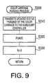
- FIG. 9 is a flowchart to illustrate a color carriage purging process to be executed in the inkjet printer 1 according to the embodiment of the present invention.
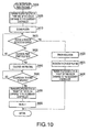
- Fig. 10 is a flowchart to illustrate a color carriage printing process to be executed in the inkjet printer 1 according to the embodiment of the present invention.
- Controlling programs for the above processes are stored in the ROM 02 of the first controlling circuit 100 and the ROM 202 of the second controlling circuit 200 and executed in parallel by the CPU 101 and the CPU 201.
- the white carriage refers to the first carriage 26 with the first print head 23 for white ink being mounted
- the color carriage refers to the second carriage 22 with the second print head 21 for CMYK inks being mounted.
- the other one of the CPUs 101, 201 is referred to as a subsidiary controller. Namely, when the CPU 101 of the first controlling circuit 100 is working as a main controller, the CPU 201 of the second controlling circuit 200 is the subsidiary controller, and vice versa.
- the CPU 101 is referred to as the main controller
- the CPU 201 is the subsidiary controller.
- the CPU 101 examines as to whether the first print start button 281 has been operated. The judgment is made based on input signals from the first sensor I/O circuit 124 of the first print control circuit 120. When an operation to the first print start button 281 is detected (S5: YES), the CPU 101 proceeds to S 10.
- the CPU 101 examines as to whether the RAM 103 of the first controlling circuit 100 contains print data representing an image to be formed. When the print data is not contained (S10: NO), in S15, the CPU 101 transmits error signals to the indicator control circuits 125 of the first print control circuit 120 so that the user can be notified of an error, for example, by a warning sound from the speaker 285. In S10, if the print data is contained in the RAM 103 (S10: YES), the CPU 101 proceeds to S20.
- the CPU 101 examines as to whether the print data contained in the RAM 103 is data to form the image in the white ink by driving the first print head 23. If the print data does not represent the image to be formed in the white ink (S20: NO), the CPU 101 proceeds to S35. If the print data represents the image to be formed in the white ink (S20: YES), the CPU 101 proceeds to S25.
- the CPU 101 examines as to whether the white carriage, i.e., the first carriage 26, is ready for the print data. If the first carriage 26 is not ready (S25: NO), the CPU 101 repeats S25 until the first carriage 26 becomes ready. When the first carriage 26 is ready (S25: YES), the CPU 101 proceeds to S30.
- status of the first and the second carriages 26, 22 includes "purging,” in which the first or the second carriage 26, 22 is being purged, "printing,” in which image forming is in progress, and "ready.” When the first or the second carriage 26, 22 is in neither of "purging” nor “printing,” the status of the first or the second carriage 26, 22 is referred to as "ready.”
- the CPU 101 examines as to whether a variable Nw, which indicates a number of printing operations conducted by the first carriage 26 after a latest purging process, is greater than or equal to a predetermined number N1. Further, the CPU 101 examines as to whether a predetermined time period has elapsed after a latest printing operation conducted by the first carriage 26. If the variable Nw indicates smaller than the predetermined number N1, and the first carriage 26 has been maintained unused for a shorter time period than the predetermined time period (S30: NO), the CPU 101 proceeds to S200.
- the CPU 101 executes a white carriage purging process, in which the nozzle surface of the first print head 23 being mounted on the first carriage 26 is purged so that ink remaining in the nozzle surface can be removed.
- the white carriage purging process will be described hereinbelow with reference to Fig. 7 .
- the CPU 101 updates the status of the first carriage 26 to "purging" and transmits the status information to the subsidiary controller (i.e., the CPU 201 of the second controlling circuit 200) through the interface 104.
- the subsidiary controller i.e., the CPU 201 of the second controlling circuit 200
- the CPU 101 executes a purging process, in which the nozzle surface of the first print head 23 is purged to remove air bubbles in the ink on the nozzle surface. More specifically, the waste valve 45 is released to open an ink path in the tube 46 to the waste tank 44. Further, the first carriage motor 25 is activated, and the first carriage 26 is moved to a predetermined purging position. Next, the valve 42 is released to open the ink path in the tube 46 to the aspiration cap. The aspiration cap is raised to the first print head 23, and the valve 42 is closed when the aspiration cap covers the nozzle surface of the first print head 23.
- the aspiration pump 43 is activated so that the ink remaining in the nozzle surface of the first print head 23 containing air bubbles is removed therefrom.
- the aspirated ink is transported through the waste ink valve 45 to the waste tank 44.
- the valve 42 is again released, and the aspiration cap is separated from the first print head 23.
- the CPU 101 initializes the variable Nw to zero and updates an origin of time period to measure the unused time period of the first carriage 26 to the time in which the current purging operation was conducted.
- the CPU 101 returns to S100 in Fig. 6 .
- the CPU 101 executes a white carriage print process, in which the image is formed by driving the first print head 23 being mounted on the first carriage 26.
- the white carriage print process will be described hereinbelow with reference to Fig. 8 .
- the CPU 101 updates the status of the first carriage 26 to "printing" and transmits the status information to the subsidiary controller through the interface 104.
- the CPU 101 transmits controlling signals to the first platen motor drive circuit 123 of the first print control circuit 120. Accordingly, the first platen drive motor 71 is activated to drive the first platen 5 to a print start position.
- the CPU 101 examines as to whether the first obstacle sensor 55 has detected an obstacle based on input signals from the first sensor I/O circuit 124 of the first print control circuit 120.
- the CPU 101 transmits controlling signals to the indicator control circuit 125 of the first print control circuit 120 transmits error signals to the indicator control circuits 125 of the first print control circuit 120 so that the user can be notified of an error, for example, by a warning sound from the speaker 285.
- the CPU 101 transmits controlling signals to the first platen motor drive circuit 123 of the first print control circuit 120 to decelerate or inactivate the first platen drive motor 71 to decelerate or stop the first platen 5.
- the CPU 101 updates the status of the first carriage 26 to "ready” and transmits the status information to the subsidiary controller through the interface 104.
- the CPU 101 returns to S200 in Fig. 6 .
- S235 when the first obstacle sensor 55 has not detected an obstacle (S215: NO), in S235, the CPU 101 examines as to whether the first platen 5 has moved to the print start position based on input signals from the first platen position sensor 291 through the first sensor I/O circuit 124 of the first print control circuit 120. When the first platen 5 has not yet been brought to the print start position (S235: NO), the CPU 101 returns to S215. When the first platen 5 has been moved to the print start position (S235: YES), the CPU 101 proceeds to S240, in which white-ink printing is performed.
- White-ink printing according to the present invention is a printing process to form an image solely in the white ink
- the colored-ink printing is a printing process to form an image in the colored inks.
- the white-ink printing can be effectively applied together with the colored-ink printing to a piece of dark-colored (e.g., black) fabric.
- colored-ink printing (see S400) according to the present invention is a printing process to form an image in the colored inks and can be effectively applied to a piece of light-colored (e.g., white) fabric.
- the CPU 101 transmits controlling signals to the first carriage motor drive circuit 122 of the first print control circuit 120, the first print head drive circuit 121, and the first platen motor drive circuit 123 to drive the first carriage 26, the first print head 23, and the first platen 5 in cooperation with one another. More specifically, the first carriage 26 is driven in the main scanning direction to eject the white ink for one line on the recording medium to form a partial image. The platen is thereafter moved in the auxiliary direction for an amount corresponding to one line, and the first carriage 26 is again driven to form a next line of the image. Thus, the image is formed on the fabric in the white ink (i.e., white-ink printing).
- the CPU 101 examines as to whether white-ink printing has completed. When white-ink printing is not completed (S245: NO), the CPU 101 repeats S245. When white-ink printing is completed (S245: YES), the CPU 101 proceeds to S250.
- the CPU 101 updates the status of the first carriage 26 to "ready” and transmits the status information to the subsidiary controller through the interface 104.
- the CPU 101 increments the variable Nw, which indicates a number of printing operations conducted by the first carriage 26 after a latest purging process, by one.
- the CPU 101 returns to S200 in Fig. 6 .
- the CPU 101 examines as to whether the print data contained in the RAM 103 is data to form the image in the colored inks by driving the second print head 21. If the print data does not represent the image to be formed in the colored inks (S35: NO), the CPU 101 proceeds to S55. If the print data represents the image to be formed in the colored inks (S35: YES), the CPU 101 proceeds to S40.
- the CPU 101 examines as to whether the obstacle sensor 55 has detected an obstacle in the white carriage print process in S200. If the obstacle sensor 55 has detected an obstacle in the white carriage print process (S40: YES), the CPU 101 proceeds to S55, and the printing operation to form the image on the fabric placed on the first platen 5 is ceased. When the obstacle sensor 55 has not detected an obstacle (S40: NO), the CPU 101 proceeds to S45.
- the CPU 101 examines as to whether the color carriage, i.e., the second carriage 22, is ready for the print data. If the second carriage 22 is not ready (S45: NO), the CPU 101 repeats S45 until the second carriage 22 becomes ready. When the second carriage 22 is ready (S45: YES), the CPU 101 proceeds to S50.
- the CPU 101 examines as to whether a variable Nc, which indicates a number of printing operations conducted by the second carriage 22 after a latest purging process, is greater than or equal to a predetermined number N2. Further, the CPU 101 examines as to whether a predetermined time period has elapsed after a latest printing operation conducted by the second carriage 22. If the variable Nc indicates smaller than the predetermined number N2, and the second carriage 22 has been maintained unused for a shorter time period than the predetermined time period (S50: NO), the CPU 101 proceeds to S400.
- a variable Nc which indicates a number of printing operations conducted by the second carriage 22 after a latest purging process
- variable Nc is greater than or equal to the predetermined number N2 (S50: YES), or the time period in which the second carriage 22 has been maintained unused is longer than or equal to the predetermined time period (S50: YES), the CPU 101 proceeds to S300.
- the CPU 101 executes a color carriage purging process, in which the nozzle surface of the second print head 21 being mounted on the second carriage 22 is purged so that ink remaining in the nozzle surface can be removed.
- the color carriage purging process will be described hereinbelow with reference to Fig. 9 .
- the CPU 101 updates the status of the second carriage 22 to "purging" and transmits the status information to the subsidiary controller (i.e., the CPU 201 of the second controlling circuit 200) through the interface 104.
- the subsidiary controller i.e., the CPU 201 of the second controlling circuit 200
- the CPU 101 executes a purging process, which is a process similar to the purging process in 120.
- a purging process which is a process similar to the purging process in 120.
- each component in the purging unit 91 for the second print head 21 replaces the components in the purging unit 41 for the first print head 23, and description of the purging process is omitted herein.
- the CPU 101 initializes the variable Nc to zero and updates an origin of time period to measure the unused time period of the second carriage 22 to the time in which the current purging operation was conducted.
- the CPU 101 returns to S300 in Fig. 6 .
- the CPU 101 executes a color carriage print process, in which the image is formed by driving the second print head 21 being mounted on the second carriage 22.
- the color carriage print process will be described hereinbelow with reference to Fig. 10 .
- the CPU 101 updates the status of the second carriage 22 to "printing" and transmits the status information to the subsidiary controller through the interface 104.
- the CPU 101 transmits controlling signals to the first platen motor drive circuit 123 of the first print control circuit 120. Accordingly, the first platen drive motor 71 is activated to drive the first platen 5 to a print start position.
- the CPU 101 examines as to whether the first obstacle sensor 55 has detected an obstacle based on input signals from the first sensor I/O circuit 124 of the first print control circuit 120.
- the CPU 101 transmits controlling signals to the indicator control circuit 125 of the first print control circuit 120 transmits error signals to the indicator control circuits 125 of the first print control circuit 120 so that the user can be notified of an error, for example, by a warning sound from the speaker 285.
- the CPU 101 transmits controlling signals to the first platen motor drive circuit 123 of the first print control circuit 120 to decelerate or inactivate the first platen drive motor 71 to decelerate or stop the first platen 5.
- the CPU 101 updates the status of the second carriage 22 to "ready” and transmits the status information to the subsidiary controller through the interface 104.
- the CPU 101 returns to S400 in Fig. 6 .
- the CPU 101 transmits controlling signals to the second carriage motor drive circuit 142 of the second print control circuit 140, the second print head drive circuit 141, and the first platen motor drive circuit 123 to drive the second carriage 22, the second print head 21, and the first platen 5 in cooperation with one another. More specifically, the second carriage 22 is driven in the main scanning direction to eject the colored inks for one line on the recording medium to form a partial image. The first platen 5 is thereafter moved in the auxiliary direction for an amount corresponding to one line, and the second carriage 22 is again driven to form a next line of the image. Thus, the image is formed on the fabric in the colored inks (i.e., colored-ink printing).
- the CPU 101 examines as to whether image forming in the colored inks has completed. When the image is not completed (S445: NO), the CPU 101 repeats S445. When forming the image in the colored inks is completed (S445: YES), the CPU 101 proceeds to S450.
- the CPU 101 updates the status of the second carriage 22 to "ready” and transmits the status information to the subsidiary controller through the interface 104.
- the CPU 101 increments the variable Nc, which indicates a number of printing operations conducted by the second carriage 22 after a latest purging process, by one.
- the CPU 101 returns to S400 in Fig. 6 .
- the CPU 101 transmits controlling signals to the first platen motor drive circuit 123 to activate the first platen drive motor 71 so that the first platen 5 is moved to a removable position, in which the fabric can be removed from the first platen 5. The process is terminated thereafter.
- the printing operation is performed similarly to the above-described process.
- Fig. 11 is a time chart to illustrate behaviors of the inkjet printer 1 when white-ink printing and colored-ink printing are performed according to the embodiment of the present invention.
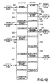
- Fig. 12 is a time chart to illustrate behaviors of the inkjet printer 1 when colored-ink printing is performed according to the embodiment of the present invention.
- Figs. 11 and 12 illustrate behaviors of the inkjet printer 1 when same print data is used to print a same image on each piece of fabric on the first and the second platens 5, 6.
- lead times required for white-printing and colored printing are illustrated to be substantially equivalent for explanation simplicity.
- Reference numerals in parentheses in the description below refer to each segmented time period in the printing operation.
- the CPU 101 of the first controlling circuit 100 performs the white carriage print process for the first recording medium by driving the first carriage 26 and the first platen 5 (503) (see S200 in Fig. 6 ).
- the status of the first carriage 26 is updated to be "printing," and the status information is transmitted to the CPU 200 of the second controlling circuit through the interface 104 (see S205 in Fig. 8 ).
- the operator sets a second recording medium on the second platen 6 (601).
- the CPU 201 of the second controlling circuit 200 refers to the status of the first carriage 26, which is "printing,” and stands by (603).
- the CPU 101 following the white carriage print process, performs the color carriage print process (see S400 in Fig. 6 ) for the first recording medium by driving the second carriage 22 and the first platen 5 (504).
- the CPU 101 updates the status of the second carriage 22 to "ready” and transmits the status information to the CPU 201 of the second controlling circuit 200 through the interface 104 (see S450 in Fig. 10 ).
- the CPU 101 drives the first platen 5 to the removable position (see S55 in Fig. 6 ).
- the operator removes the first recording medium with the image formed thereon from the first platen 5 (505).
- the printing processes to a first piece of the first recording medium are completed.
- the CPU 201 updates the status of the first carriage 26 to "ready” and transmits the status information to the CPU 101 of the first controlling circuit 100 through the interface 104 (see S250 in Fig. 8 ). Thereafter, the CPU 201 refers to the status of the second carriage 22, which is "ready” and successively performs the color carriage print process for the second recording medium by driving the second carriage 22 and the second platen 6 (605). After completion of the color carriage print process, the CPU 201 drives the second platen 6 to the removable position (see S55 in Fig. 6 ). The operator removes the second recording medium with the image formed thereon from the second platen 6 (606). The printing processes to a first piece of the second recording medium are completed.
- the operation to the second print start button 271 allows the operator to make reservation of the following operations, i.e., the white carnage print process and the color carriage print process.
- the operator sets a second piece of the first recording medium on the first platen 5 (506).
- the CPU 101 performs the white carriage print process for the first recording medium by driving the first carriage 26 and the first platen 5 (508).
- the CPU 101 successively performs the color carriage print process for the first recording medium by driving the second carriage 22 and the first platen 5 (509).
- the CPU 101 drives the first platen 5 to the removable position. Accordingly, the operator removes the first recording medium with the image formed thereon from the first platen 5 (510).
- printing processes to the first piece of the first recording medium are completed.
- the operator sets a second piece of the second recording medium on the second platen 6 (607).
- the CPU 201 performs the white carriage print process for the second recording medium by driving the first carriage 26 and the second platen 6 (609).
- the variable Nw indicating a number of printing operations conducted by the first carriage 26 after a latest purging process is greater than or equal to the predetermined number N1 (see S255 in Fig. 8 )
- the CPU 201 successively performs the color carriage print process for the second recording medium by driving the second carriage 22 and the second platen 5 (610).
- the CPU 201 drives the second platen 6 to the removable position. Accordingly, the operator removes the first recording medium with the image formed thereon from the second platen 6 (611). Thus, printing processes to the second piece of the second recording medium are completed.
- the operator sets a third piece of the first recording medium on the first platen 5 (511).
- the CPU 101 performs the white carriage purging process, in which ink in the nozzle surface of the first print head 23 on the first carriage 26 is removed (513) (see also S30 and S100 in Fig. 6 ).
- the CPU 101 updates the status of the first carriage 26 to "purging" and transmits the status information to the CPU 201 of the second controlling circuit 200 through the interface 104 (see S110 in Fig. 7 ).
- the operator after operating the first print start button 281 to start printing the image on the third piece of the first recording medium, sets a third piece of the second recording medium on the second platen 6 whilst the white carriage purging process by driving the first carriage 26 is in progress (612).
- the CPU 201 of the second controlling circuit 200 refers to the status of the first carriage 26, which is "purging," and stands by (614) (see also S25 in Fig. 6 ).
- the CPU 101 maintains the status of the first carriage 26 to be "purging" (see Fig. 7 ) and performs the white carriage print process by driving the first carriage 26 for the first recording medium on the first platen 5 (514). Accordingly, the CPU 201 maintains the standby state (614). Thereafter, upon completion of the white-ink printing, the CPU 101 updates the status of the first carriage 26 to "ready” and transmits the status information to the CPU 201 of the second controlling circuit 200 through the interface 104 (see S250 in Fig. 8 ). Accordingly, the CPU 201 releases the first carriage 26 to be driven to perform the white carriage print process with the third piece of the second recording medium (615) (see also S25 and S200 in Fig. 6 ).
- the CPU 101 drives the first platen 5 to the removable position. Accordingly, the operator removes the third piece of the first recording medium with the image formed thereon from the first platen 5 (516). Thus, printing processes to the third piece of the first recording medium are completed.
- the CPU 201 successively performs the color carriage print process by driving the second carriage 22 and the second platen 6 to the second recording medium (616).
- the CPU 201 drives the second platen 6 to the removable position (see S55 in Fig. 6 ). Accordingly, the operator removes the third piece of the second recording medium with the image formed thereon from the second platen 6 (617). Thus, printing processes to the third piece of the second recording medium are completed.
- the operation to the second print start button 271 allows the operator to make reservation of the following operations, i.e., the white carriage print process and the color carriage print process.
- Fig. 12 is a time chart to illustrate behaviors of the inkjet printer 1 when colored-ink printing is performed according to the embodiment of the present invention.
- the CPU 101 of the first controlling circuit 100 performs the color carriage print process (see S400 in Fig. 6 ) for the first recording medium by driving the second carriage 22 and the first platen 5 (523).
- the CPU 101 updates the status of the second carriage 22 to "printing" and transmits the status information to the CPU 201 of the second controlling circuit 200 through the interface 104 (see S405 in Fig. 10 ).
- the operator Whilst the color carriage print process is in progress, the operator sets a first piece of a second recording medium on the second platen 6 (621).
- the CPU 201 refers to the status of the second carriage 22, which is "printing,” and stands by (623) (see S45 in Fig. 6 ).
- the CPU 101 updates the status of the second carriage 22 to "ready” and transmits the status information to the CPU 201 of the second controlling circuit 200 through the interface 104 (see S450 in Fig. 10 ). Accordingly, the CPU 201 releases the second carriage 22 to be driven to perform the color carriage print process for the second recording medium (624) (see also S45 and S400 in Fig. 6 ).
- the CPU 101 drives the first platen 5 to the removable position (see S55 in Fig. 6 ).
- the operator removes the first recording medium with the image formed thereon from the first platen 5 (524).
- the printing processes to a first piece of the first recording medium are completed.
- the operator Whilst the color carriage print process for the second recording medium is in progress (624), the operator sets a second piece of the first recording medium on the first platen 5 (525).
- the CPU 101 refers to the status of the second carriage 22, which is "printing," and stands by (527) (see S45 in Fig. 6 ).
- the CPU 201 updates the status of the second carriage 22 to "ready” and transmits the status information to the CPU 101 of the first controlling circuit 100 through the interface 104 (see S450 in Fig. 10 ). Accordingly, the CPU 101 releases the second carriage 22 to be driven to perform the color carriage print process with the second piece of the first recording medium (528) (see also S45 and S400 in Fig. 6 ).
- the CPU 201 drives the second platen 6 to the removable position (see S55 in Fig. 6 ).
- the operator removes the second recording medium with the image formed thereon from the second platen 6 (625).
- the printing processes to a first piece of the second recording medium are completed.
- the operation to the second print start button 271 allows the operator to make reservation of the following operations, i.e., the color carriage print process.
- the operator sets a third piece of the first recording medium on the first platen 5 (529).
- the CPU 101 refers to the status of the second carriage 20, which is "printing,” and stands by (531) (see also S45 in Fig. 6 ).
- the CPU 201 Upon completion of the color carriage print process with the second carriage 22 and the second recording medium, the CPU 201 updates the status of the second carriage 22 to "ready” and transmits the status information to the CPU 101 (see S450 in Fig. 10 ). In this regard, if the variable Nc is greater than or equal to the predetermined number N2, the CPU 101 performs the color carriage purging process, in which ink in the nozzle surface of the second print head 21 on the second carriage 22 is removed (532) (see also S45, S50, and S300 in Fig. 6 ). Further, the CPU 101 updates the status of the second carriage 22 to "purging" and transmits the status information to the CPU 201 of the second controlling circuit 200 through the interface 104 (see S310 in Fig. 9 ).
- the operator sets a third piece of the second recording medium on the second platen 6 whilst the color carriage purging process by driving the second carriage 22 is in progress (627).
- the CPU 201 of the second controlling circuit 200 refers to the status of the second carriage 22, which is "purging," and stands by (629) (see also S45 in Fig. 6 ).
- the CPU 101 maintains the status of the second carriage 22 to be "purging" (see Fig. 9 ) and performs the color carriage print process by driving the second carriage 22 for the first recording medium on the first platen 5 (533). Accordingly, the CPU 201 maintains the standby state (629). Thereafter, upon completion of the colored-ink printing, the CPU 101 updates the status of the second carriage 22 to "ready” and transmits the status information to the CPU 201 of the second controlling circuit 200 through the interface 104 (see S450 in Fig. 10 ). Accordingly, the CPU 201 releases the second carriage 22 to be driven to perform the color carriage print process with the third piece of the second recording medium (630) (see also S45 and S400 in Fig. 6 ).
- the operation to the second print start button 271 allows the operator to make reservation of the following operations, i.e., the color carriage print process for the second recording medium.
- the printing operation to the second recording medium on the second platen 6 is started after completion of the printing operation to the first recording medium (e.g., following the colored-ink printing (523) in Fig. 12 ) or in between the printing processes (e.g., following white-ink printing (503) and during colored-ink printing (504) in Fig. 11 ) for the first recording medium.
- the first recording medium e.g., following the colored-ink printing (523) in Fig. 12
- the printing processes e.g., following white-ink printing (503) and during colored-ink printing (504) in Fig. 11
- operations following a currently performed printing operation can be reserved; therefore, the operator is not required to wait at the inkjet printer 1 until the currently performed operation is completed. Because the waiting period for the operator can be omitted, the series of printing operations with a plurality of pieces of recording media can be conducted efficiently.
- the white carriage print process with the first print head 23 and the first recording medium is performed under control of the CPU 101, and the white carriage print process with the first print head 23 and the second recording medium follows thereafter under control of the CPU 201.
- the color carriage print process with the second print head 23 and the first recording medium is performed under control of the CPU 101, and the color carriage print process with the second print head 21 and the second recording medium follows thereafter under control of the CPU 201.
- the white carriage print processes under control of the CPU 101 and the CPU 201 can be successively performed.
- the color carriage print processes under control of the CPU 101 and the CPU 201 can be successively performed. Therefore, inactive periods for the print heads 23, 21 can be reduced so that operation efficiency can be even more improved.
- the printing process for the second recording medium is started after completion of the printing process for the first recording medium which follows the purging process (e.g., following colored-ink printing (533) in Fig. 12 ), or in between the printing processes after purging (e.g., following white-ink printing (514) and during colored-ink printing (515) in Fig. 11 ) for the first recording medium.
- the purging process e.g., following colored-ink printing (533) in Fig. 12
- purging e.g., following white-ink printing (533) in Fig. 12
- purging e.g., following white-ink printing (533) in Fig. 12
- purging e.g., following white-ink printing (533) in Fig. 12
- purging e.g., following white-ink printing (514) and during colored-ink printing (515) in Fig. 11
- height of the recording media is detected by the obstacle sensors 55, 56 at the start of the printing processes with the first and the second recording media.
- a height of the first recording medium being higher than a predetermined threshold is detected, whilst a following printing process for the second recording medium is reserved, the printing process for the second recording medium is started so that the inkjet printer 1 can be maintained running with less inactive period.
- operation efficiency can be even more improved.
- the inkjet printer 1 is equipped with two print heads, which include the first print head 23 for white-ink printing and the second print head 21 for colored-ink printing. Therefore, finely-adjusted color gradation can be achieved.
- the CPU 101 of the first controlling circuit 100 can control behaviors of the first platen 5 and white-ink printing with the first carriage 26, and the CPU 201 of the second controlling circuit 200 can control behaviors of the second platen 6 and colored-ink printing with the second carriage 22.
- the CPU 101 and the CPU 201 can exchange controlling information through the interface 104 to control the respective platens.
- two CPUs which are the CPU 101 and the CPU 201, may not necessarily be provided, but a single CPU to control the entire inkjet printer 1 may be provided.
- driving the second platen 6 to start the printing process is started after completion of a preceding printing process for the first recording medium.
- driving the second platen 6 may not necessarily be paused until completion of the preceding printing process.
- the first platen 5 for the first recording medium may be moved to a print start position (e.g., a first position), in which the first print head 23 starts printing, before completion of the preceding printing process for the second recording medium.
- the second platen 6 may be moved to a print start position (e.g., a second position), in which the second print head 21 starts printing before completion of the preceding printing process for the first recording medium.
- a print start position e.g., a second position
- the first and the second recording media for the following printing process can stand by at the print start positions so that the inkjet printer 1 can be maintained running with less inactive period.
- operation efficiency can be even more improved.
- the status information indicating behaviors of the first carriage 26 and the second carriage 22 includes “purging,” “printing,” and “ready.”
- the status information can include information to indicate other behaviors such as “wiping,” which indicates that the nozzle surfaces of the first and the second print heads 23, 21 are being wiped.
- a white-ink printing process for the second recording medium is started after completion of a preceding white-ink printing process for the first recording medium.
- a white-ink printing process for the second recording medium can be started after completion of white-ink printing and colored-ink printing processes for the first recording medium.
Landscapes
- Engineering & Computer Science (AREA)
- Textile Engineering (AREA)
- Ink Jet (AREA)
- Accessory Devices And Overall Control Thereof (AREA)
- Dot-Matrix Printers And Others (AREA)
Abstract
Description
- This application claims priority from Japanese Patent Application No.
2008-075698, filed on March 24, 2008 - An aspect of the present invention relates to a printing apparatus, more specifically, a printing apparatus to print images on fabrics.
- Conventionally, a printing apparatus for printing an image on a piece of fabric, having a platen to hold the fabric, a print head to eject inks onto the fabric, a carriage to move the print head, an operation plane, and a set of colored inks, has been known. Such a printing apparatus is disclosed in, for example, Japanese Patent Provisional Publication No.
2004-268506 - For another example, in United States Patent Application Publication No.
US 2005/0179708 A1 , a printing apparatus having a plurality of platens to hold a plurality of pieces of fabric aligned on a same horizontal plane is disclosed. According to the latter publication, two images are successively formed on the respective pieces of fabric in inks ejected from a print head so that the images can be formed successively on the plurality of pieces of fabric in shorter lead time. - When the images are formed in the printing apparatus disclosed in the latter publication, an operator can remove a piece of fabric with the image being formed from one of the platens and load a new piece of fabric thereon while an image is formed on another piece of fabric loaded on the other platen so that the images can be formed continuously and thus efficiently.
- When the images are formed successively on the pieces of fabric placed on two platens, although it is not explicitly described in the above mentioned publications, it is assumed that the operator is generally required to stand by the printing apparatus and await a current printing operation to the fabric placed on one platen to be completed so that an instruction to start a printing operation to the fabric placed on the other platen can be entered upon completion of the current printing operation. Therefore, the waiting periods to reduce work efficiency of the operator are caused.
- In view of the above, the present invention is advantageous in that a printing apparatus capable of printing images successively with less waiting periods for an operator so that work efficiency of the operator is improved, is provided.
- According to an aspect of the invention, a printing apparatus capable of forming images successively on a plurality of pieces of recording media. The printing apparatus includes at least two platens including a first platen to hold a first recording medium and a second platen to hold a second recording medium, at least one print head, which is driven according to print data to eject ink onto the first recording medium and the second recording medium, at least one print head drive unit to drive the at least one print head in a main scanning direction, at least two platen drive units to drive each of the at least two platens including a first platen drive unit to drive the first platen in an auxiliary direction, which is perpendicular to the main scanning direction, and a second platen drive unit to drive the second platen in the auxiliary direction, at least one ink cartridge to store ink therein and supply the ink to the at least one print head, at least two operation input units to be operated by an operator to instruct the printing apparatus to activate printing processes, including a first operation input unit to instruct a first printing process to form an image on the first recording medium by activating the at least one print head, the at least one print head drive unit, and the first platen drive unit and a second operation input unit to instruct a second printing process to form an image on the second recording medium by activating the at least one print head, the at least one print head drive unit, and the second platen drive unit, and a cooperation controller system to control the at least one print head, the at least one print head drive unit, the first platen drive unit, and the second platen drive unit to behave in cooperation with one another so that the second printing process is started one of after completion of the first printing process and during the first printing process when an instruction to start the second printing process is entered through the second operation input unit whilst the first printing process is in progress.
- With the printing apparatus according to the above configuration, the second printing operation can be reserved so that the second printing operation can be started efficiently after completion of the first printing process or during the first printing process. Thus, the operator is not required to stand by the printing apparatus and await the first printing process to be completed, and operation efficiency of the operator can be improved.
-
-
Fig. 1 is a top plane view of an inkjet printer according to an embodiment of the present invention. -
Fig. 2 is a front view of the inkjet printer according to the embodiment of the present invention. -
Fig. 3 is a block diagram to illustrate an electrical configuration of the inkjet printer according to the embodiment of the present invention. -
Fig. 4 is an illustrative top view of a drive mechanism of a platen according to the embodiment of the present invention. -
Fig. 5 is an illustrative side view of the drive mechanism of the platen according to the embodiment of the present invention. -
Fig. 6 is a flowchart to illustrate a print controlling operation executed by CPUs in a first and a second controlling circuits according to the embodiment of the present invention. -
Fig. 7 is a flowchart to illustrate a white carriage purging process to be executed in the inkjet printer according to the embodiment of the present invention. -
Fig. 8 is a flowchart to illustrate a white carriage printing process to be executed in the inkjet printer according to the embodiment of the present invention. -
Fig. 9 is a flowchart to illustrate a color carriage purging process to be executed in the inkjet printer according to the embodiment of the present invention. -
Fig. 10 is a flowchart to illustrate a color carriage printing process to be executed in the inkjet printer according to the embodiment of the present invention. -
Fig. 11 is a time chart to illustrate behaviors of the inkjet printer when white-ink printing and colored-ink printing are performed in the inkjet printer according to the embodiment of the present invention. -
Fig. 12 is a time chart to illustrate behaviors of the inkjet printer when colored-ink printing is performed in the inkjet printer according to the embodiment of the present invention. - Hereinafter, an embodiment according to an aspect of the present invention will be described with reference to the accompanying drawings.
- An
inkjet printer 1 according to the embodiment of the present invention will be described with reference toFigs. 1 through 3 .Fig. 1 is a top plane view of theinkjet printer 1 according to the embodiment of the present invention.Fig. 2 is a front view of theinkjet printer 1 according to the embodiment of the present invention.Fig. 3 is a block diagram to illustrate an electrical configuration of theinkjet printer 1 according to the embodiment of the present invention. - The
inkjet printer 1 according to the present embodiment is a inkjet printer having afirst print head 23 to eject opaque white (W) ink onto a recording medium and asecond print head 21, from which inks in colors of cyan (C), magenta (M), yellow (Y), and black (K) are ejected onto the recording medium. The recording medium in the present embodiment is a piece of fabric, more specifically a T-shirt, and an image according to image data inputted in theinkjet printer 1 from an external data processing apparatus is formed on the T-shirt. As shown inFigs. 1 and2 , theinkjet printer 1 is provided with aflat base 2 at a bottom thereof and acasing 10 to cover an entire configuration of theinkjet printer 1. - In the present embodiment, a left-hand side which appears in
Fig. 1 is referred to as the front side of theinkjet printer 1. Further, an upper side inFig. 1 and a left-hand side inFig 2 correspond to the left end of theinkjet printer 1. Accordingly, a lower side inFig. 1 and a right-hand side inFig. 2 correspond to the right end of theinkjet printer 1. In addition, a direction, in which afirst carriage 26 with the first thefirst print head 23 mounted thereon and asecond carriage 22 with thesecond print heads 21 mounted thereon are reciprocated, corresponds to a main scanning direction (i.e., a vertical direction inFig. 1 ) of theprint heads - Inside the
casing 10, theinkjet printer 1 is provided with an inkjet printing mechanism, which includes thefirst print head 23, thefirst carriage 26, and aguide rail 12. Theguide rail 12 is arranged in parallel with the main scanning direction to guide thecarriage 26 with theprint head 23 there-along. Further, afirst carriage motor 25, a pulley (not shown), and a carriage belt (not shown) are provided. Thefirst carriage motor 25 is in vicinity to one end (an upper end inFig. 1 in the present embodiment) of theguide rail 12, and the pulley is in vicinity to the other end (a lower end inFig. 1 ). The carriage belt is provided to connect thefirst carriage motor 25 and the pulley. The carriage belt is fixed to a rear side of thefirst carriage 26 so that thefirst carriage 26 can be reciprocated along theguide rail 12 as the carriage belt is driven by thefirst carriage motor 25. - The
inkjet printer 1 is further provided with a purging unit 41 for thefirst print head 23 on the right-hand end of theguide rail 12. The purging unit 41 includes, as shown inFig. 2 , a suction cap (not shown) which can be closely attached to and separated from a nozzle surface of thefirst print head 23, avalve 42 to adjust air pressure in the suction cap, a suction pump 43 to aspirate ink in the nozzles, awaste ink tank 44 to store the aspirated ink, awaste ink valve 45 to control flows of the ink to thewaste ink tank 44, andtubes 46 to connect the above components. Thevalve 42 is opened to release air immediately before the suction cap becomes in contact with thefirst print head 23 and closed when the suction cap becomes in contact with thefirst print head 23. Thevalve 42 is again opened before the suction cap is separated from thefirst print head 23. Thus, air pressure in the suction cap is adjusted so that generation of air bubbles in the ink in the suction cap can be prevented. When the suction cap is in contact with thefirst print head 23, the suction pump 43 can be activated in order to aspirate and remove ink containing air bubbles from the nozzle surface of thefirst print head 23. - Further inside the
casing 10, theinkjet printer 1 is provided with aguide rail 11, which is arranged in parallel with the main scanning direction to guide asecond carriage 22 with theprint head 21 there-along. Furthermore, asecond carriage motor 24, a pulley (not shown), and a carriage belt (not shown) are provided. Thesecond carriage motor 24 is in vicinity to one end (an upper end inFig. 1 in the present embodiment) of theguide rail 11, and the pulley is in vicinity to the other end (a lower end inFig. 1 ). The carriage belt is provided to connect thesecond carriage motor 24 and the pulley. The carriage belt is fixed to a rear side of thesecond carriage 22 so that thesecond carriage 22 can be reciprocated along theguide rail 11 as the carriage belt is driven by thesecond carriage motor 24. - On the left-hand side of the
guide rail 11, as shown inFig. 2 , apurging unit 91 for thesecond print head 21, which is in a similar configuration to the purging unit 41, to aspirate ink containing air bubbles from a nozzle surface of thesecond print head 21 is provided. Thepurging unit 91 includes a suction cap (not shown), avalve 92, asuction pump 93, a waste tank 94, and awaste ink valve 95, andtubes 96. - Next, platens of the
inkjet printer 1 according to the present embodiment to hold the recording medium will de described. Theinkjet printer 1 is provided with a pair of platens, afirst platen 5 and asecond platen 6, which are identical to each other. Thefirst platen 5 and thesecond platen 6 are movable in parallel with an auxiliary scanning direction, which is substantially perpendicular to the main scanning direction of the print head 21 (i.e., a horizontal direction inFig. 1 ). - In order to drive the
platens inkjet printer 1 is provided with a first drive mechanism 7 and asecond drive mechanism 8, which are arranged in parallel with each other. The first drive mechanism 7 is to drive thefirst platen 5 and includesguide rails 77, 77 (seeFig. 2 ) and a firstplaten drive motor 71. The firstplaten drive motor 71, which is a stepping motor in the present embodiment, is arranged on one end (a right-hand end inFig. 1 ) of each of the guide rails 77, 77. The firstplaten drive motor 71 is arranged in vicinity to a rear end (the right-hand end inFig. 1 ) in the casing 10.As the firstplaten drive motor 71 is activated, thefirst platen 5 is reciprocated in the auxiliary direction along the guide rails 77, 77. - Similarly, the
second drive mechanism 8 is provided to drive thesecond platen 6 and includesguide rails 87, 87 (seeFig. 2 ) and a secondplaten drive motor 81, which is a stepping motor. Thesecond platen 6 is reciprocated in the auxiliary direction along the guide rails 87, 87 as the secondplaten drive motor 81 is activated. The secondplaten drive motor 81 is arranged in vicinity to the rear end (the right-hand end inFig. 1 ) in thecasing 10. - Each of the
first platen 5 and thesecond platen 6 is formed to have a pentagonal shape in a plane view. More specifically, a front end of each platen is formed in an obtuse V-like shape protruding toward the front of theinkjet printer 1 so that the recording medium (i.e., a T-shirt in the present embodiment) can be placed horizontally over a top surface of the platen. In the present embodiment, hereinafter, a recording medium (i.e., a piece of fabric in the present embodiment) being set over thefirst platen 5 is referred to as a first recording medium, and a recording medium being set over thesecond platen 6 is referred to as a second recording medium. - The
inkjet printer 1 is further provided with afirst obstacle sensor 55 and asecond obstacle sensor 65 on the front side (left-hand side inFig. 1 ) with respect to theguide rail 11 above thefirst platen 5 and thesecond platen 6 respectively. Thefirst obstacle sensor 55 and thesecond obstacle sensor 65 detect height of objects (i.e., the recording media) on the first and thesecond platens first obstacle sensor 55 includes asensing plate 56,shafts sensing plate 56, extending in the main scanning direction, is positioned in thefirst obstacle sensor 55 to have a predetermined clearance between a lower end thereof and a top surface of theplaten 5. Thesensing plate 56 is fixed to theshafts second obstacle sensor 65 is in a similar configuration to thefirst obstacle sensor 55 and includes asensing plate 66,shafts second platens sensing plates inkjet printer 1. Accordingly, thesensing plates sensing plates - Furthermore, as shown in
Fig. 2 ,trays second platens second platens trays second platens second platens trays second platens trays platens trays base 2 when the T-shirts are installed on thefirst platen 5 and thesecond platen 6. - The
inkjet printer 1 is provided with a first inkcartridge storage unit 32, in whichink cartridges casing 10, as shown inFig. 2 . Theink cartridges cartridge storage unit 32 by fixingmembers inkjet printer 1 is further provided with a second inkcartridge storage unit 31, in whichink cartridges casing 10, as shown inFig. 2 . Theink cartridges cartridge storage unit 31 by fixingmembers ink cartridges - As shown in
Figs. 1 and2 , theinkjet printer 1 is further provided with afirst operation panel 28 on the right-hand side of the front thereof. Thefirst operation panel 28 includes a plurality of operation buttons, through which a user's operations to manipulate thefirst platen 5, the first or the second print head 23 (21), and the first or the second carriage 26 (22) are inputted, such as a firstprint start button 281 to instruct printing on the fabric placed on thefirst platen 5 and a first cancelbutton 283 to instruct cancellation of the printing instruction. Further, thefirst operation panel 28 includes a display 284 (an LCD (liquid crystal display) in the present embodiment) to display various information concerning the operation, a first print data obtainbutton 282 to instruct obtainment of print data, adata lamp 286 to indicate reception of the print data, and anerror lamp 287 to indicate an operation error. Thefirst operation panel 28 further includes aspeaker 285 to generate a warning sound. - Also as shown in
Figs. 1 and2 , theinkjet printer 1 is provided with asecond operation panel 27 on the left-hand side of the front thereof. Thesecond operation panel 27 includes a plurality of operation buttons, through which a user's operations to manipulate thesecond platen 6, the second or the first print head 21 (23), and the second or the first carriage 22 (26) are inputted, such as a secondprint start button 271 to instruct printing on the fabric placed on thesecond platen 6 and a second cancelbutton 273 to instruct cancellation of the printing instruction. Further, thesecond operation panel 27 includes a display 274 (an LCD in the present embodiment) to display various information concerning the operation, a second print data obtainbutton 272 to instruct obtainment of print data, adata lamp 276 to indicate reception of the print data, and anerror lamp 277 to indicate an operation error. Thesecond operation panel 27 also includes aspeaker 275 to generate a warning sound. - Next, referring to
Fig. 3 , an electrical configuration of theinkjet printer 1 according to the present embodiment will be described.Fig. 3 is a block diagram to illustrate the electrical configuration of theinkjet printer 1 according to the embodiment of the present invention. Theinkjet printer 1 includes a firstcontrolling circuit 100, a secondcontrolling circuit 200, a firstprint control circuit 120, and a secondprint control circuit 140. - The first
controlling circuit 100 is a circuit to control a printing operation to print an image on the fabric supported by thefirst platen 5, including driving thefirst platen 5, the first and thesecond carriages controlling circuit 100 is provided within thefirst operation panel 28 and includes aCPU 101, aROM 102 to store various controlling programs to be executed by theCPU 101, and aRAM 103 to temporarily store various data. The secondcontrolling circuit 200 is a circuit to control a printing operation to print an image on the fabric supported by thesecond platen 6, including driving thesecond platen 6, the second and thefirst carriages controlling circuit 140 is provided within thesecond operation panel 27 and includes aCPU 201, aROM 202, and aRAM 203, similarly to the firstcontrolling circuit 100. The firstcontrolling circuit 100 and the secondcontrolling circuit 200 are connected to each other through an interface 104 (e.g., LVDS (low voltage differential signaling)) to exchange information therebetween and share various information necessary to control the operations. Further, the first and the secondcontrolling circuits print control circuit 120 and the secondprint control circuit 140 through the interface 104 andbuses controlling circuits communication unit 107. - The first
print control circuit 120 is a circuit to control behaviors of thefirst platen 5, thefirst print head 23, and thefirst carriage 26 and includes a first printhead drive circuit 121, a first carriagemotor drive circuit 122, and a first platenmotor drive circuit 123. The first printhead drive circuit 121 is to activate and inactivate piezoelectric actuators in each channel in thefirst print head 23. The first carriagemotor drive circuit 122 is to activate and inactivate thefirst carriage motor 25, and the first platenmotor drive circuit 123 is to activate and inactivate the firstplaten drive motor 71. The firstprint control circuit 120 further includes a first sensor I/O circuit 124 and anindicator control circuit 125. The first sensor I/O circuit 124 accepts information inputted by the firstprint start button 281, the first print data obtainbutton 282, the first cancelbutton 283, awarning stop button 288 to stop the warning sound from thespeaker 285, a firstplaten position sensor 291, which is to detect a position of thefirst platen 5, and thefirst obstacle sensor 55. Theindicator control circuit 125 controls thedata lamp 286, theerror lamp 287, awarning indicator lamp 289, which indicates thewarning stop button 288 needs to be operated, thedisplay 284, and thespeaker 285. - The second
print control circuit 140 is a circuit to control behaviors of thesecond platen 6, thesecond print head 21, and thesecond carriage 22 and includes a second printhead drive circuit 141, a second carriagemotor drive circuit 142, and a second platenmotor drive circuit 143. The second printhead drive circuit 141 is to activate and inactivate piezoelectric actuators in each channel in thesecond print head 21. The second carriagemotor drive circuit 142 is to activate and inactivate thesecond carriage motor 24, and the second platenmotor drive circuit 143 is to activate and inactivate the secondplaten drive motor 81. The secondprint control circuit 140 further includes a second sensor I/O circuit 144 and anindicator control circuit 145. The second sensor I/O circuit 144 accepts information inputted by the secondprint start button 271, the second print data obtainbutton 272, the second cancelbutton 273, awarning stop button 278 to stop the warning sound from thespeaker 275, a secondplaten position sensor 292, which is to detect a position of thesecond platen 6, and thesecond obstacle sensor 65. Theindicator control circuit 145 controls thedata lamp 276, theerror lamp 277, awarning indicator lamp 279, which indicates thewarning stop button 278 needs to be operated, thedisplay 274, and thespeaker 275. - Next, referring to
Figs. 4 and 5 , the first drive mechanism 7 to drive thefirst platen 5 will be described.Fig. 4 is an illustrative top view of the first drive mechanism 7 according to the embodiment of the present invention.Fig. 5 is an illustrative side view of the first drive mechanism according to the embodiment of the present invention. The left-hand side which appears inFigs. 4 and 5 corresponds to the front of theinkjet printer 1, and the right-hand side which appears inFigs. 4 and 5 corresponds to the rear of theinkjet printer 1. - The first drive mechanism 7 is provided with a
motor pulley 73, agreater pulley 72, and amotor belt 79, and themotor belt 79 encircles themotor pulley 73 and thegreater pulley 72. As the firstplaten drive motor 71 rotates, themotor pulley 73 is rotated, and thegreater pulley 72 is rotated accordingly. The first drive mechanism 7 is provided with afirst belt pulley 74, which is attached to thegreater pulley 72 to rotate coaxially and in synchronization with thegreater pulley 72. The firstplaten drive motor 71, themotor pulley 73, thegreater pulley 72, and thefirst belt pulley 74 are arranged in thecasing 10 in positions lower than a horizontal plane on which thefirst platen 5 is shifted. Further, atiming belt 78 is provided to encircle thefirst belt pulley 74 and asecond belt pulley 75. Thesecond belt pulley 75 is provided in a position closer to the front of the inkjet printer 1 (i.e., on the left-hand side inFigs. 1 ,4, and 5 ). A diameter of thesecond belt pulley 75 is substantially equivalent to a diameter of thefirst belt pulley 74. - In the
inkjet printer 1, thefirst belt pulley 74 and thesecond belt pulley 75 are arranged in positions such that a line connecting a rotation axis of thefirst belt pulley 74 and a center of thesecond belt pulley 75 is perpendicular to the main scanning direction of the first print head 23 (i.e., an axial direction of the guide rail 12), and thetiming belt 78 is oriented perpendicularly to the main scanning direction of thefirst print head 23. Thetiming belt 78 is fixed to thefirst platen 5 by aplaten attachment 51 so that thefirst platen 5 is shifted in a direction indicated by an arrow A inFigs. 4 and 5 (i.e., the auxiliary scanning direction and a front-rear direction of the inkjet printer 1) as thetiming belt 78 is shifted in accordance with rotation of thefirst belt pulley 74. Thus, rotation of the firstplaten drive motor 71 is conveyed to themotor pulley 73, themotor belt 79, thegreater pulley 72, thefirst belt pulley 74, thetiming belt 78, thesecond belt pulley 75, and theplaten attachment 51, and thus converted into horizontal movement to shift thefirst platen 5 in the auxiliary direction. - The
second drive mechanism 8 is in a similar configuration to the configuration of the first drive mechanism 7, and description of that is herein omitted. - Next, with reference to
Figs. 6 through 10 , control flows of a printing operation in theinkjet printer 1 according to the embodiment of the present invention will be described.Fig. 6 is a flowchart to illustrate a print controlling operation executed by theCPU 101 in the firstcontrolling circuit 100 and theCPU 201 of the secondcontrolling circuit 200 according to the embodiment of the present invention.Fig. 7 is a flowchart to illustrate a white carriage purging process to be executed in theinkjet printer 1 according to the embodiment of the present invention.Fig. 8 is a flowchart to illustrate a white carriage printing process to be executed in theinkjet printer 1 according to the embodiment of the present invention.Fig. 9 is a flowchart to illustrate a color carriage purging process to be executed in theinkjet printer 1 according to the embodiment of the present invention.Fig. 10 is a flowchart to illustrate a color carriage printing process to be executed in theinkjet printer 1 according to the embodiment of the present invention. Controlling programs for the above processes are stored in the ROM 02 of the firstcontrolling circuit 100 and theROM 202 of the secondcontrolling circuit 200 and executed in parallel by theCPU 101 and theCPU 201. - In the description below and
Figs. 6-10 , the white carriage refers to thefirst carriage 26 with thefirst print head 23 for white ink being mounted, and the color carriage refers to thesecond carriage 22 with thesecond print head 21 for CMYK inks being mounted. Further, in the description below andFigs. 7-10 , when one of theCPUs controlling circuits CPUs CPU 101 of the firstcontrolling circuit 100 is working as a main controller, theCPU 201 of the secondcontrolling circuit 200 is the subsidiary controller, and vice versa. In the present embodiment hereinbelow, theCPU 101 is referred to as the main controller, and theCPU 201 is the subsidiary controller. - When the print controlling operation starts, as shown in
Fig. 6 , in S5, theCPU 101 examines as to whether the firstprint start button 281 has been operated. The judgment is made based on input signals from the first sensor I/O circuit 124 of the firstprint control circuit 120. When an operation to the firstprint start button 281 is detected (S5: YES), theCPU 101 proceeds toS 10. - In S10, the
CPU 101 examines as to whether theRAM 103 of the firstcontrolling circuit 100 contains print data representing an image to be formed. When the print data is not contained (S10: NO), in S15, theCPU 101 transmits error signals to theindicator control circuits 125 of the firstprint control circuit 120 so that the user can be notified of an error, for example, by a warning sound from thespeaker 285. In S10, if the print data is contained in the RAM 103 (S10: YES), theCPU 101 proceeds to S20. - In S20, the
CPU 101 examines as to whether the print data contained in theRAM 103 is data to form the image in the white ink by driving thefirst print head 23. If the print data does not represent the image to be formed in the white ink (S20: NO), theCPU 101 proceeds to S35. If the print data represents the image to be formed in the white ink (S20: YES), theCPU 101 proceeds to S25. - In S25, the
CPU 101 examines as to whether the white carriage, i.e., thefirst carriage 26, is ready for the print data. If thefirst carriage 26 is not ready (S25: NO), theCPU 101 repeats S25 until thefirst carriage 26 becomes ready. When thefirst carriage 26 is ready (S25: YES), theCPU 101 proceeds to S30. In the present embodiment, status of the first and thesecond carriages second carriage second carriage second carriage - In S30, the
CPU 101 examines as to whether a variable Nw, which indicates a number of printing operations conducted by thefirst carriage 26 after a latest purging process, is greater than or equal to a predetermined number N1. Further, theCPU 101 examines as to whether a predetermined time period has elapsed after a latest printing operation conducted by thefirst carriage 26. If the variable Nw indicates smaller than the predetermined number N1, and thefirst carriage 26 has been maintained unused for a shorter time period than the predetermined time period (S30: NO), theCPU 101 proceeds to S200. If the variable Nw is greater than or equal to the predetermined number N1 (S30: YES), or the time period in which thefirst carriage 26 has been maintained unused is longer than or equal to the predetermined time period (S30: YES), theCPU 101 proceeds to S100. - In S100, the
CPU 101 executes a white carriage purging process, in which the nozzle surface of thefirst print head 23 being mounted on thefirst carriage 26 is purged so that ink remaining in the nozzle surface can be removed. The white carriage purging process will be described hereinbelow with reference toFig. 7 . - When the white carriage purging process starts, in
S 110, theCPU 101 updates the status of thefirst carriage 26 to "purging" and transmits the status information to the subsidiary controller (i.e., theCPU 201 of the second controlling circuit 200) through the interface 104. - In
S 120, theCPU 101 executes a purging process, in which the nozzle surface of thefirst print head 23 is purged to remove air bubbles in the ink on the nozzle surface. More specifically, thewaste valve 45 is released to open an ink path in thetube 46 to thewaste tank 44. Further, thefirst carriage motor 25 is activated, and thefirst carriage 26 is moved to a predetermined purging position. Next, thevalve 42 is released to open the ink path in thetube 46 to the aspiration cap. The aspiration cap is raised to thefirst print head 23, and thevalve 42 is closed when the aspiration cap covers the nozzle surface of thefirst print head 23. The aspiration pump 43 is activated so that the ink remaining in the nozzle surface of thefirst print head 23 containing air bubbles is removed therefrom. The aspirated ink is transported through thewaste ink valve 45 to thewaste tank 44. Thevalve 42 is again released, and the aspiration cap is separated from thefirst print head 23. - In S130, the
CPU 101 initializes the variable Nw to zero and updates an origin of time period to measure the unused time period of thefirst carriage 26 to the time in which the current purging operation was conducted. TheCPU 101 returns to S100 inFig. 6 . - Following S100, in S200, the
CPU 101 executes a white carriage print process, in which the image is formed by driving thefirst print head 23 being mounted on thefirst carriage 26. The white carriage print process will be described hereinbelow with reference toFig. 8 . - When the white carriage print process starts, in S205, the
CPU 101 updates the status of thefirst carriage 26 to "printing" and transmits the status information to the subsidiary controller through the interface 104. - In S210, the
CPU 101 transmits controlling signals to the first platenmotor drive circuit 123 of the firstprint control circuit 120. Accordingly, the firstplaten drive motor 71 is activated to drive thefirst platen 5 to a print start position. - In S215, the
CPU 101 examines as to whether thefirst obstacle sensor 55 has detected an obstacle based on input signals from the first sensor I/O circuit 124 of the firstprint control circuit 120. When thefirst obstacle sensor 55 has detected an obstacle (S215: YES), in S220, theCPU 101 transmits controlling signals to theindicator control circuit 125 of the firstprint control circuit 120 transmits error signals to theindicator control circuits 125 of the firstprint control circuit 120 so that the user can be notified of an error, for example, by a warning sound from thespeaker 285. - In S225, the
CPU 101 transmits controlling signals to the first platenmotor drive circuit 123 of the firstprint control circuit 120 to decelerate or inactivate the firstplaten drive motor 71 to decelerate or stop thefirst platen 5. - In S230, the
CPU 101 updates the status of thefirst carriage 26 to "ready" and transmits the status information to the subsidiary controller through the interface 104. TheCPU 101 returns to S200 inFig. 6 . - In S215, when the
first obstacle sensor 55 has not detected an obstacle (S215: NO), in S235, theCPU 101 examines as to whether thefirst platen 5 has moved to the print start position based on input signals from the firstplaten position sensor 291 through the first sensor I/O circuit 124 of the firstprint control circuit 120. When thefirst platen 5 has not yet been brought to the print start position (S235: NO), theCPU 101 returns to S215. When thefirst platen 5 has been moved to the print start position (S235: YES), theCPU 101 proceeds to S240, in which white-ink printing is performed. - White-ink printing according to the present invention is a printing process to form an image solely in the white ink, and the colored-ink printing is a printing process to form an image in the colored inks. The white-ink printing can be effectively applied together with the colored-ink printing to a piece of dark-colored (e.g., black) fabric. Meanwhile, colored-ink printing (see S400) according to the present invention is a printing process to form an image in the colored inks and can be effectively applied to a piece of light-colored (e.g., white) fabric.
- In S240, the
CPU 101 transmits controlling signals to the first carriagemotor drive circuit 122 of the firstprint control circuit 120, the first printhead drive circuit 121, and the first platenmotor drive circuit 123 to drive thefirst carriage 26, thefirst print head 23, and thefirst platen 5 in cooperation with one another. More specifically, thefirst carriage 26 is driven in the main scanning direction to eject the white ink for one line on the recording medium to form a partial image. The platen is thereafter moved in the auxiliary direction for an amount corresponding to one line, and thefirst carriage 26 is again driven to form a next line of the image. Thus, the image is formed on the fabric in the white ink (i.e., white-ink printing). - In S245, the
CPU 101 examines as to whether white-ink printing has completed. When white-ink printing is not completed (S245: NO), theCPU 101 repeats S245. When white-ink printing is completed (S245: YES), theCPU 101 proceeds to S250. - In S250, the
CPU 101 updates the status of thefirst carriage 26 to "ready" and transmits the status information to the subsidiary controller through the interface 104. - In S255, the
CPU 101 increments the variable Nw, which indicates a number of printing operations conducted by thefirst carriage 26 after a latest purging process, by one. TheCPU 101 returns to S200 inFig. 6 . - Following S200 in
Fig. 6 , in S35, theCPU 101 examines as to whether the print data contained in theRAM 103 is data to form the image in the colored inks by driving thesecond print head 21. If the print data does not represent the image to be formed in the colored inks (S35: NO), theCPU 101 proceeds to S55. If the print data represents the image to be formed in the colored inks (S35: YES), theCPU 101 proceeds to S40. - In S40, the
CPU 101 examines as to whether theobstacle sensor 55 has detected an obstacle in the white carriage print process in S200. If theobstacle sensor 55 has detected an obstacle in the white carriage print process (S40: YES), theCPU 101 proceeds to S55, and the printing operation to form the image on the fabric placed on thefirst platen 5 is ceased. When theobstacle sensor 55 has not detected an obstacle (S40: NO), theCPU 101 proceeds to S45. - In S45, the
CPU 101 examines as to whether the color carriage, i.e., thesecond carriage 22, is ready for the print data. If thesecond carriage 22 is not ready (S45: NO), theCPU 101 repeats S45 until thesecond carriage 22 becomes ready. When thesecond carriage 22 is ready (S45: YES), theCPU 101 proceeds to S50. - In S50, the
CPU 101 examines as to whether a variable Nc, which indicates a number of printing operations conducted by thesecond carriage 22 after a latest purging process, is greater than or equal to a predetermined number N2. Further, theCPU 101 examines as to whether a predetermined time period has elapsed after a latest printing operation conducted by thesecond carriage 22. If the variable Nc indicates smaller than the predetermined number N2, and thesecond carriage 22 has been maintained unused for a shorter time period than the predetermined time period (S50: NO), theCPU 101 proceeds to S400. If the variable Nc is greater than or equal to the predetermined number N2 (S50: YES), or the time period in which thesecond carriage 22 has been maintained unused is longer than or equal to the predetermined time period (S50: YES), theCPU 101 proceeds to S300. - In S300, the
CPU 101 executes a color carriage purging process, in which the nozzle surface of thesecond print head 21 being mounted on thesecond carriage 22 is purged so that ink remaining in the nozzle surface can be removed. The color carriage purging process will be described hereinbelow with reference toFig. 9 . - When the color carriage purging process starts, in S310, the
CPU 101 updates the status of thesecond carriage 22 to "purging" and transmits the status information to the subsidiary controller (i.e., theCPU 201 of the second controlling circuit 200) through the interface 104. - In S320, the
CPU 101 executes a purging process, which is a process similar to the purging process in 120. In the purging process in S320, each component in thepurging unit 91 for thesecond print head 21 replaces the components in the purging unit 41 for thefirst print head 23, and description of the purging process is omitted herein. - In S330, the
CPU 101 initializes the variable Nc to zero and updates an origin of time period to measure the unused time period of thesecond carriage 22 to the time in which the current purging operation was conducted. TheCPU 101 returns to S300 inFig. 6 . - Following S300, in S400, the
CPU 101 executes a color carriage print process, in which the image is formed by driving thesecond print head 21 being mounted on thesecond carriage 22. The color carriage print process will be described hereinbelow with reference toFig. 10 . - When the color carriage print process starts, in S405, the
CPU 101 updates the status of thesecond carriage 22 to "printing" and transmits the status information to the subsidiary controller through the interface 104. - In S410, the
CPU 101 transmits controlling signals to the first platenmotor drive circuit 123 of the firstprint control circuit 120. Accordingly, the firstplaten drive motor 71 is activated to drive thefirst platen 5 to a print start position. - In S415, the
CPU 101 examines as to whether thefirst obstacle sensor 55 has detected an obstacle based on input signals from the first sensor I/O circuit 124 of the firstprint control circuit 120. When thefirst obstacle sensor 55 has detected an obstacle (S415: YES), in S420, theCPU 101 transmits controlling signals to theindicator control circuit 125 of the firstprint control circuit 120 transmits error signals to theindicator control circuits 125 of the firstprint control circuit 120 so that the user can be notified of an error, for example, by a warning sound from thespeaker 285. - In S425, the
CPU 101 transmits controlling signals to the first platenmotor drive circuit 123 of the firstprint control circuit 120 to decelerate or inactivate the firstplaten drive motor 71 to decelerate or stop thefirst platen 5. - In S430, the
CPU 101 updates the status of thesecond carriage 22 to "ready" and transmits the status information to the subsidiary controller through the interface 104. TheCPU 101 returns to S400 inFig. 6 . - In S415, when the
first obstacle sensor 55 has not detected an obstacle (S415: NO), in S435, theCPU 101 examines as to whether thefirst platen 5 has moved to the print start position based on input signals from the firstplaten position sensor 291 through the first sensor I/O circuit 124 of the firstprint control circuit 120. When thefirst platen 5 has not yet been brought to the print start position (S435: NO), theCPU 101 returns to S415. When thefirst platen 5 has been moved to the print start position (S435: YES), theCPU 101 proceeds to S440, in which colored-ink printing is performed. - In S440, the
CPU 101 transmits controlling signals to the second carriagemotor drive circuit 142 of the secondprint control circuit 140, the second printhead drive circuit 141, and the first platenmotor drive circuit 123 to drive thesecond carriage 22, thesecond print head 21, and thefirst platen 5 in cooperation with one another. More specifically, thesecond carriage 22 is driven in the main scanning direction to eject the colored inks for one line on the recording medium to form a partial image. Thefirst platen 5 is thereafter moved in the auxiliary direction for an amount corresponding to one line, and thesecond carriage 22 is again driven to form a next line of the image. Thus, the image is formed on the fabric in the colored inks (i.e., colored-ink printing). - In S445, the
CPU 101 examines as to whether image forming in the colored inks has completed. When the image is not completed (S445: NO), theCPU 101 repeats S445. When forming the image in the colored inks is completed (S445: YES), theCPU 101 proceeds to S450. - In S450, the
CPU 101 updates the status of thesecond carriage 22 to "ready" and transmits the status information to the subsidiary controller through the interface 104. - In S455, the
CPU 101 increments the variable Nc, which indicates a number of printing operations conducted by thesecond carriage 22 after a latest purging process, by one. TheCPU 101 returns to S400 inFig. 6 . - Following S400 in
Fig. 6 , in S55, theCPU 101 transmits controlling signals to the first platenmotor drive circuit 123 to activate the firstplaten drive motor 71 so that thefirst platen 5 is moved to a removable position, in which the fabric can be removed from thefirst platen 5. The process is terminated thereafter. - Although detailed description of the printing operation when the
CPU 201 of the secondcontrolling circuit 200 is the main controller and theCPU 101 of the firstcontrolling circuit 100 is the subsidiary controller, the printing operation is performed similarly to the above-described process. - Next, with reference to
Figs. 11 and12 , behaviors of theinkjet printer 1 in the printing operation will be described.Fig. 11 is a time chart to illustrate behaviors of theinkjet printer 1 when white-ink printing and colored-ink printing are performed according to the embodiment of the present invention.Fig. 12 is a time chart to illustrate behaviors of theinkjet printer 1 when colored-ink printing is performed according to the embodiment of the present invention.Figs. 11 and12 illustrate behaviors of theinkjet printer 1 when same print data is used to print a same image on each piece of fabric on the first and thesecond platens Figs. 11 and12 , lead times required for white-printing and colored printing are illustrated to be substantially equivalent for explanation simplicity. Reference numerals in parentheses in the description below refer to each segmented time period in the printing operation. - As shown in
Fig. 11 , when the operator sets a first recording medium on the first platen 5 (501) and operates the firstprint start button 281 in the first operation panel 28 (502), theCPU 101 of the firstcontrolling circuit 100 performs the white carriage print process for the first recording medium by driving thefirst carriage 26 and the first platen 5 (503) (see S200 inFig. 6 ). At this point, the status of thefirst carriage 26 is updated to be "printing," and the status information is transmitted to theCPU 200 of the second controlling circuit through the interface 104 (see S205 inFig. 8 ). - Whilst the white carriage print process is in progress, the operator sets a second recording medium on the second platen 6 (601). When the operator operates the second
print start button 271 in the second operation panel 27 (602), theCPU 201 of the secondcontrolling circuit 200 refers to the status of thefirst carriage 26, which is "printing," and stands by (603). - When the white-ink printing completes, status of the
first carriage 26 is updated to be "ready," and theCPU 101 transmits the status information to theCPU 201 of the secondcontrolling circuit 200 through the interface 104 (see S250 inFig. 8 ). TheCPU 201 releases thefirst carriage 26 to be driven to perform the white carriage print process for the second recording medium (604). - Meanwhile, the
CPU 101, following the white carriage print process, performs the color carriage print process (see S400 inFig. 6 ) for the first recording medium by driving thesecond carriage 22 and the first platen 5 (504). When the color carriage print process is completed, theCPU 101 updates the status of thesecond carriage 22 to "ready" and transmits the status information to theCPU 201 of the secondcontrolling circuit 200 through the interface 104 (see S450 inFig. 10 ). TheCPU 101 drives thefirst platen 5 to the removable position (see S55 inFig. 6 ). The operator removes the first recording medium with the image formed thereon from the first platen 5 (505). Thus, the printing processes to a first piece of the first recording medium are completed. - Meanwhile, when the white carriage print process is completed, the
CPU 201 updates the status of thefirst carriage 26 to "ready" and transmits the status information to theCPU 101 of the firstcontrolling circuit 100 through the interface 104 (see S250 inFig. 8 ). Thereafter, theCPU 201 refers to the status of thesecond carriage 22, which is "ready" and successively performs the color carriage print process for the second recording medium by driving thesecond carriage 22 and the second platen 6 (605). After completion of the color carriage print process, theCPU 201 drives thesecond platen 6 to the removable position (see S55 inFig. 6 ). The operator removes the second recording medium with the image formed thereon from the second platen 6 (606). The printing processes to a first piece of the second recording medium are completed. - Thus, whilst the white carriage print process with the
first carriage 26 and the first recording medium is performed, the operation to the secondprint start button 271 allows the operator to make reservation of the following operations, i.e., the white carnage print process and the color carriage print process. - Next, the operator sets a second piece of the first recording medium on the first platen 5 (506). When the operator operates the first
print start button 281 in the first operation panel 28 (507), theCPU 101 performs the white carriage print process for the first recording medium by driving thefirst carriage 26 and the first platen 5 (508). Upon completion of the white carriage print process, theCPU 101 successively performs the color carriage print process for the first recording medium by driving thesecond carriage 22 and the first platen 5 (509). When the color carriage print process is completed, theCPU 101 drives thefirst platen 5 to the removable position. Accordingly, the operator removes the first recording medium with the image formed thereon from the first platen 5 (510). Thus, printing processes to the first piece of the first recording medium are completed. - Meanwhile, the operator sets a second piece of the second recording medium on the second platen 6 (607). When the operator operates the second
print start button 271 in the second operation panel 27 (608), theCPU 201 performs the white carriage print process for the second recording medium by driving thefirst carriage 26 and the second platen 6 (609). In this regard, if the variable Nw indicating a number of printing operations conducted by thefirst carriage 26 after a latest purging process is greater than or equal to the predetermined number N1 (see S255 inFig. 8 ), upon completion of the white carriage print process, theCPU 201 successively performs the color carriage print process for the second recording medium by driving thesecond carriage 22 and the second platen 5 (610). When the color carriage print process is completed, theCPU 201 drives thesecond platen 6 to the removable position. Accordingly, the operator removes the first recording medium with the image formed thereon from the second platen 6 (611). Thus, printing processes to the second piece of the second recording medium are completed. - Next, the operator sets a third piece of the first recording medium on the first platen 5 (511). When the operator operates the first
print start button 281 in the first operation panel 28 (512), based on the variable Nw being greater than or equal to the predetermined number N1, theCPU 101 performs the white carriage purging process, in which ink in the nozzle surface of thefirst print head 23 on thefirst carriage 26 is removed (513) (see also S30 and S100 inFig. 6 ). In this regard, theCPU 101 updates the status of thefirst carriage 26 to "purging" and transmits the status information to theCPU 201 of the secondcontrolling circuit 200 through the interface 104 (see S110 inFig. 7 ). - The operator, after operating the first
print start button 281 to start printing the image on the third piece of the first recording medium, sets a third piece of the second recording medium on thesecond platen 6 whilst the white carriage purging process by driving thefirst carriage 26 is in progress (612). When the operator operates the secondprint start button 271 in the second operation panel 27 (613), theCPU 201 of the secondcontrolling circuit 200 refers to the status of thefirst carriage 26, which is "purging," and stands by (614) (see also S25 inFig. 6 ). - When the purging process of the
first carriage 26 is completed, theCPU 101 maintains the status of thefirst carriage 26 to be "purging" (seeFig. 7 ) and performs the white carriage print process by driving thefirst carriage 26 for the first recording medium on the first platen 5 (514). Accordingly, theCPU 201 maintains the standby state (614). Thereafter, upon completion of the white-ink printing, theCPU 101 updates the status of thefirst carriage 26 to "ready" and transmits the status information to theCPU 201 of the secondcontrolling circuit 200 through the interface 104 (see S250 inFig. 8 ). Accordingly, theCPU 201 releases thefirst carriage 26 to be driven to perform the white carriage print process with the third piece of the second recording medium (615) (see also S25 and S200 inFig. 6 ). - When the color carriage print process is completed (515), the
CPU 101 drives thefirst platen 5 to the removable position. Accordingly, the operator removes the third piece of the first recording medium with the image formed thereon from the first platen 5 (516). Thus, printing processes to the third piece of the first recording medium are completed. - Meanwhile, when the white carriage print process for the second recording medium is completed, the
CPU 201 successively performs the color carriage print process by driving thesecond carriage 22 and thesecond platen 6 to the second recording medium (616). Upon completion of the color carriage print process, theCPU 201 drives thesecond platen 6 to the removable position (see S55 inFig. 6 ). Accordingly, the operator removes the third piece of the second recording medium with the image formed thereon from the second platen 6 (617). Thus, printing processes to the third piece of the second recording medium are completed. - Thus, whilst the white carriage purging process with the
first carriage 26 is performed, the operation to the secondprint start button 271 allows the operator to make reservation of the following operations, i.e., the white carriage print process and the color carriage print process. - It is to be noted that similar printing processes can be further performed to fourth or more recording media, however, description of those are herein omitted. During the white carriage print process and the color carriage print processes described above, when an error is detected by the
obstacle sensors first carriage 26 or thesecond carriage 22 is changed to be "ready", and the status information is transmitted to the subsidiary controller (see S230 inFig. 8 and S430 inFig. 10 ). When the subsidiary controller received the status information, and if theprint start button - Next, with reference to
Fig. 12 , behaviors of theinkjet printer 1 in the printing operation, when solely a colored-ink printing is performed, will be described.Fig. 12 is a time chart to illustrate behaviors of theinkjet printer 1 when colored-ink printing is performed according to the embodiment of the present invention. - As shown in
Fig. 12 , when the operator sets a first recording medium on the first platen 5 (521) and operates the firstprint start button 281 in the first operation panel 28 (522), theCPU 101 of the firstcontrolling circuit 100 performs the color carriage print process (see S400 inFig. 6 ) for the first recording medium by driving thesecond carriage 22 and the first platen 5 (523). In this regard, theCPU 101 updates the status of thesecond carriage 22 to "printing" and transmits the status information to theCPU 201 of the secondcontrolling circuit 200 through the interface 104 (see S405 inFig. 10 ). - Whilst the color carriage print process is in progress, the operator sets a first piece of a second recording medium on the second platen 6 (621). When the operator operates the second
print start button 271 in the second operation panel 27 (622), theCPU 201 refers to the status of thesecond carriage 22, which is "printing," and stands by (623) (see S45 inFig. 6 ). - When the color carriage print process for the first recording medium is completed, the
CPU 101 updates the status of thesecond carriage 22 to "ready" and transmits the status information to theCPU 201 of the secondcontrolling circuit 200 through the interface 104 (see S450 inFig. 10 ). Accordingly, theCPU 201 releases thesecond carriage 22 to be driven to perform the color carriage print process for the second recording medium (624) (see also S45 and S400 inFig. 6 ). - Thereafter, the
CPU 101 drives thefirst platen 5 to the removable position (see S55 inFig. 6 ). The operator removes the first recording medium with the image formed thereon from the first platen 5 (524). Thus, the printing processes to a first piece of the first recording medium are completed. - Whilst the color carriage print process for the second recording medium is in progress (624), the operator sets a second piece of the first recording medium on the first platen 5 (525). When the operator operates the first
print start button 281 in the first operation panel 28 (526), theCPU 101 refers to the status of thesecond carriage 22, which is "printing," and stands by (527) (see S45 inFig. 6 ). - Meanwhile, when the color carriage print process for the second recording medium is completed, the
CPU 201 updates the status of thesecond carriage 22 to "ready" and transmits the status information to theCPU 101 of the firstcontrolling circuit 100 through the interface 104 (see S450 inFig. 10 ). Accordingly, theCPU 101 releases thesecond carriage 22 to be driven to perform the color carriage print process with the second piece of the first recording medium (528) (see also S45 and S400 inFig. 6 ). - Thereafter, the
CPU 201 drives thesecond platen 6 to the removable position (see S55 inFig. 6 ). The operator removes the second recording medium with the image formed thereon from the second platen 6 (625). Thus, the printing processes to a first piece of the second recording medium are completed. - Thus, whilst the color carriage print process with the
first carriage 26 and the first recording medium (alternatively, the second recording medium) is performed, the operation to the second print start button 271 (alternatively, the first print start button 281) allows the operator to make reservation of the following operations, i.e., the color carriage print process. - Thereafter, whilst the color carriage print process with the
second carriage 22 and the second recording medium is in progress (626), the operator sets a third piece of the first recording medium on the first platen 5 (529). When the operator operates the firstprint start button 281 in the first operation panel 28 (530), theCPU 101 refers to the status of the second carriage 20, which is "printing," and stands by (531) (see also S45 inFig. 6 ). - Upon completion of the color carriage print process with the
second carriage 22 and the second recording medium, theCPU 201 updates the status of thesecond carriage 22 to "ready" and transmits the status information to the CPU 101 (see S450 inFig. 10 ). In this regard, if the variable Nc is greater than or equal to the predetermined number N2, theCPU 101 performs the color carriage purging process, in which ink in the nozzle surface of thesecond print head 21 on thesecond carriage 22 is removed (532) (see also S45, S50, and S300 inFig. 6 ). Further, theCPU 101 updates the status of thesecond carriage 22 to "purging" and transmits the status information to theCPU 201 of the secondcontrolling circuit 200 through the interface 104 (see S310 inFig. 9 ). - The operator sets a third piece of the second recording medium on the
second platen 6 whilst the color carriage purging process by driving thesecond carriage 22 is in progress (627). When the operator operates the secondprint start button 271 in the second operation panel 27 (628), theCPU 201 of the secondcontrolling circuit 200 refers to the status of thesecond carriage 22, which is "purging," and stands by (629) (see also S45 inFig. 6 ). - When the purging process of the
second carriage 22 is completed, theCPU 101 maintains the status of thesecond carriage 22 to be "purging" (seeFig. 9 ) and performs the color carriage print process by driving thesecond carriage 22 for the first recording medium on the first platen 5 (533). Accordingly, theCPU 201 maintains the standby state (629). Thereafter, upon completion of the colored-ink printing, theCPU 101 updates the status of thesecond carriage 22 to "ready" and transmits the status information to theCPU 201 of the secondcontrolling circuit 200 through the interface 104 (see S450 inFig. 10 ). Accordingly, theCPU 201 releases thesecond carriage 22 to be driven to perform the color carriage print process with the third piece of the second recording medium (630) (see also S45 and S400 inFig. 6 ). - Thus, whilst the color carriage purging process with the
second carriage 22 is performed, the operation to the secondprint start button 271 allows the operator to make reservation of the following operations, i.e., the color carriage print process for the second recording medium. - It is to be noted that similar printing processes can be further performed to fourth or more recording media, however, description of those are herein omitted. During the color carriage print process described above, when an error is detected by the
obstacle sensors second carriage 22 is changed to be "ready", and the status information is transmitted to the subsidiary controller (see S430 inFig. 10 ). When the subsidiary controller received the status information, and if theprint start button - According to the
inkjet printer 1 described above, when an operation to the secondprint start button 271 is entered while the printing operation to the first recording medium on thefirst platen 5 is in progress, the printing operation to the second recording medium on thesecond platen 6 is started after completion of the printing operation to the first recording medium (e.g., following the colored-ink printing (523) inFig. 12 ) or in between the printing processes (e.g., following white-ink printing (503) and during colored-ink printing (504) inFig. 11 ) for the first recording medium. Thus, operations following a currently performed printing operation can be reserved; therefore, the operator is not required to wait at theinkjet printer 1 until the currently performed operation is completed. Because the waiting period for the operator can be omitted, the series of printing operations with a plurality of pieces of recording media can be conducted efficiently. - According to the
inkjet printer 1 in the above embodiment, specifically, when the operator starts the printing operation to the first recording medium on thefirst platen 5 and thereafter operates the secondprint start button 271, the white carriage print process with thefirst print head 23 and the first recording medium is performed under control of theCPU 101, and the white carriage print process with thefirst print head 23 and the second recording medium follows thereafter under control of theCPU 201. Further, the color carriage print process with thesecond print head 23 and the first recording medium is performed under control of theCPU 101, and the color carriage print process with thesecond print head 21 and the second recording medium follows thereafter under control of theCPU 201. Thus, the white carriage print processes under control of theCPU 101 and theCPU 201 can be successively performed. Similarly, the color carriage print processes under control of theCPU 101 and theCPU 201 can be successively performed. Therefore, inactive periods for the print heads 23, 21 can be reduced so that operation efficiency can be even more improved. - According to the
inkjet printer 1 in the above embodiment, further, when an operation to the secondprint start button 271 is entered while thefirst print head 23 is in the "purging" state, the printing process for the second recording medium is started after completion of the printing process for the first recording medium which follows the purging process (e.g., following colored-ink printing (533) inFig. 12 ), or in between the printing processes after purging (e.g., following white-ink printing (514) and during colored-ink printing (515) inFig. 11 ) for the first recording medium. Thus, operations following a currently performed purging operation can be reserved; therefore, operation efficiency for the operator can be even more improved. - In the above embodiment, height of the recording media is detected by the
obstacle sensors inkjet printer 1 can be maintained running with less inactive period. Thus, operation efficiency can be even more improved. - The
inkjet printer 1 according to the above embodiment is equipped with two print heads, which include thefirst print head 23 for white-ink printing and thesecond print head 21 for colored-ink printing. Therefore, finely-adjusted color gradation can be achieved. - Although an example of carrying out the invention has been described, those skilled in the art will appreciate that there are numerous variations and permutations of the printing apparatus that falls within the spirit and scope of the invention as set forth in the appended claims. It is to be understood that the subject matter defmed in the appended claims is not necessarily limited to the specific features or act described above. Rather, the specific features and acts described above are disclosed as example forms of implementing the claims.
- For example, the
CPU 101 of the firstcontrolling circuit 100 can control behaviors of thefirst platen 5 and white-ink printing with thefirst carriage 26, and theCPU 201 of the secondcontrolling circuit 200 can control behaviors of thesecond platen 6 and colored-ink printing with thesecond carriage 22. In this configuration, when colored-ink printing with thesecond carriage 22 is conducted to form an image on the first recording medium on thefirst platen 5, and when white-ink printing with thefirst carriage 26 is conducted to form an image on the second recording medium on thesecond platen 6, theCPU 101 and theCPU 201 can exchange controlling information through the interface 104 to control the respective platens. - For another example, two CPUs, which are the
CPU 101 and theCPU 201, may not necessarily be provided, but a single CPU to control theentire inkjet printer 1 may be provided. - Further, in the above embodiment, when a printing process for the second recording medium is reserved, driving the
second platen 6 to start the printing process is started after completion of a preceding printing process for the first recording medium. However, driving thesecond platen 6 may not necessarily be paused until completion of the preceding printing process. For example, when a printing process for the first recording medium is reserved, thefirst platen 5 for the first recording medium may be moved to a print start position (e.g., a first position), in which thefirst print head 23 starts printing, before completion of the preceding printing process for the second recording medium. Similarly, when a printing process for the second recording medium is reserved, thesecond platen 6 may be moved to a print start position (e.g., a second position), in which thesecond print head 21 starts printing before completion of the preceding printing process for the first recording medium. Thus, the first and the second recording media for the following printing process can stand by at the print start positions so that theinkjet printer 1 can be maintained running with less inactive period. Thus, operation efficiency can be even more improved. - In the above embodiment, the status information indicating behaviors of the
first carriage 26 and thesecond carriage 22 includes "purging," "printing," and "ready." However, the status information can include information to indicate other behaviors such as "wiping," which indicates that the nozzle surfaces of the first and the second print heads 23, 21 are being wiped. - Furthermore, in the above embodiment, when white-ink printing and colored-ink printing are performed, and a printing process for the second recording medium is reserved, a white-ink printing process for the second recording medium is started after completion of a preceding white-ink printing process for the first recording medium. However, a white-ink printing process for the second recording medium can be started after completion of white-ink printing and colored-ink printing processes for the first recording medium.
Claims (7)
- A printing apparatus capable of forming images successively on a plurality of pieces of recording media, comprising:at least two platens including a first platen to hold a first recording medium and a second platen to hold a second recording medium;at least one print head, which is driven according to print data to eject ink onto the first recording medium and the second recording medium;at least one print head drive unit to drive the at least one print head in a main scanning direction;at least two platen drive units to drive each of the at least two platens including a first platen drive unit to drive the first platen in an auxiliary direction, which is perpendicular to the main scanning direction, and a second platen drive unit to drive the second platen in the auxiliary direction;at least one ink cartridge to store ink therein and supply the ink to the at least one print head;at least two operation input units to be operated by an operator to instruct the printing apparatus to activate printing processes, including a first operation input unit to instruct a first printing process to form an image on the first recording medium by activating the at least one print head, the at least one print head drive unit, and the first platen drive unit and a second operation input unit to instruct a second printing process to form an image on the second recording medium by activating the at least one print head, the at least one print head drive unit, and the second platen drive unit; anda cooperation controller system to control the at least one print head, the at least one print head drive unit, the first platen drive unit, and the second platen drive unit to behave in cooperation with one another so that the second printing process is started one of after completion of the first printing process and during the first printing process when an instruction to start the second printing process is entered through the second operation input unit whilst the first printing process is in progress.
- The printing apparatus according to claim 1, comprising:a plurality of print heads including a first print head and a second print head, each of which is capable of ejecting the ink on to the first recording medium and the second recording medium;a plurality of print head drive units including a first print head drive unit, which drives the first print head in the main scanning direction, and a second print head drive unit, which drives the second print head in the main scanning direction; anda plurality of ink cartridges including a first ink cartridge to supply ink to the first print head and a second ink cartridge to supply ink to the second print head,wherein the first operation input unit is operated by the operator to instruct the first printing process to form the image on the first recording medium by activating the first print head, the second print head, the first print head drive unit, the second print head drive unit, and the first platen drive unit;
wherein the second operation input unit is operated by the operator to instruct the second printing process to form the image on the second recording medium by activating the first print head, the second print head, the first print head drive unit, the second print head drive unit, and the second platen drive unit; and
wherein the cooperation controller system controls the first print head, the second print head, the first print head drive unit, the second print head drive unit, the first platen drive unit, and the second platen drive unit to behave in cooperation with one another so that the second printing process is started one of after completion of the first printing process and during the first printing process when the instruction to start the second printing process is entered through the second operation input unit whilst the first printing process is in progress. - The printing apparatus according to claim 2,
wherein the cooperation controller system includes:a first print head controller, which controls cooperation of the first print head, the first print head drive unit, the first platen drive unit, and the second platen drive unit to form the images on the first recording medium in the first printing process and on the second recording medium in the second printing process;a second print head controller, which controls cooperation of the second print head, the second print head drive unit, the first platen drive unit, and the second platen drive unit to form the images on the first recording medium in the first printing process and on the second recording medium in the second printing process; andwherein the cooperation controller system controls the first print head, the second print head, the first print head drive unit, the second print head drive unit, the first platen drive unit, and the second platen drive unit to behave in cooperation with one another so that the second printing process controlled by one of the first print head controller and the second print head controller is started one of after completion of the first printing process controlled by one of the first print head controller and the second print head controller and during the first printing process when the instruction to start the second printing process is entered through the second operation input unit whilst the first printing process controlled by one of the first print head controller and the second print head controller is in progress. - The printing apparatus according to claim 3,
wherein the first print head is configured to perform a first ejecting operation, in which the first print head ejects ink onto the first recording medium in the first printing process, and a second ejecting operation, in which the first print head ejects ink onto the second recording medium in the second printing process;
wherein the second print head is configured to perform a third ejecting operation, in which the second print head ejects ink onto the first recording medium in the first printing process, and a fourth ejecting operation, in which the second print head ejects ink onto the second recording medium in the second printing process;
wherein, when the instruction to start the second printing process is entered through the second operation input unit during the first printing process is in progress, the first print head controller controls the first print head to start the second ejecting operation after completion of the first ejecting operation, and the second print head controller controls the second print head to start the fourth ejecting operation after completion of the third ejecting operation. - The printing apparatus according to any of claims 2 through 4, further comprising
a purging unit to remove air bubbles in the ink in the first print head and the second print head,
wherein the first printing process includes a removal operation to remove the air bubbles in the first print head;
wherein the cooperation controller system controls the first print head, the second print head, the first print head drive unit, the second print head drive unit, the first platen drive unit, and the second platen drive unit to behave in cooperation with one another so that the second printing process is started one of after completion of the first printing process and during the first printing process when the instruction to start the second printing process is entered through the second operation input unit whilst the removal operation to remove the air bubbles in the first print head is in progress. - The printing apparatus according to any of claims 2 through 5,
wherein the cooperation controller system includes:a first drive controller to control the first platen drive unit to move the first recording medium placed on the first platen to a first position, in which the first print head starts forming the image in the first printing process; anda second drive controller to control the second platen drive unit to move the second recording medium placed on the second platen to a second position, in which the first print head starts forming image in the second printing process;wherein the first printing process includes setting the first recording medium in the first position;
wherein the second printing process includes setting the second recording medium in the second position; and
wherein the second drive controller controls the second platen drive unit to move the second recording medium placed on the second platen to the second position when the instruction to start the second printing process is entered through the second operation input unit whilst the first printing process is in progress. - The printing apparatus according to claim 6, further comprising:a detecting unit to detect heights of the first recording medium on the first platen which is driven by the first platen drive unit and the second recording medium on the second platen which is driven by the second platen drive unit,wherein, when the instruction to start the second printing process is entered through the second operation input unit whilst the first printing process is in progress, and when a detected height of the first recording medium on the first platen being driven to the first position is greater than or equal to a predetermined threshold, the cooperation controller system controls the first print head, the second print head, the first print head drive unit, the second print head drive unit, and the second platen drive unit to behave in cooperation with one another to start the second printing process including setting the second recording medium in the second position.
Applications Claiming Priority (1)
| Application Number | Priority Date | Filing Date | Title |
|---|---|---|---|
| JP2008075698A JP5062427B2 (en) | 2008-03-24 | 2008-03-24 | Printing device |
Publications (1)
| Publication Number | Publication Date |
|---|---|
| EP2105312A1 true EP2105312A1 (en) | 2009-09-30 |
Family
ID=40823572
Family Applications (1)
| Application Number | Title | Priority Date | Filing Date |
|---|---|---|---|
| EP09155345A Withdrawn EP2105312A1 (en) | 2008-03-24 | 2009-03-17 | Printing apparatus comprising at least two platens |
Country Status (3)
| Country | Link |
|---|---|
| US (1) | US8186825B2 (en) |
| EP (1) | EP2105312A1 (en) |
| JP (1) | JP5062427B2 (en) |
Families Citing this family (9)
| Publication number | Priority date | Publication date | Assignee | Title |
|---|---|---|---|---|
| CN102582244A (en) * | 2011-01-11 | 2012-07-18 | 于丰 | Dual-workbench and multi-station digital printing machine of garments |
| JP5831691B2 (en) * | 2011-08-29 | 2015-12-09 | セイコーエプソン株式会社 | Inkjet printing device |
| JP6142474B2 (en) * | 2012-06-27 | 2017-06-07 | セイコーエプソン株式会社 | Inkjet printing system |
| JP6079158B2 (en) * | 2012-11-13 | 2017-02-15 | セイコーエプソン株式会社 | Inkjet printing system |
| JP6225485B2 (en) * | 2012-12-17 | 2017-11-08 | セイコーエプソン株式会社 | Liquid ejecting apparatus and control method thereof |
| KR101473213B1 (en) * | 2013-06-20 | 2014-12-22 | 주식회사 디지아이 | Digital printing machine |
| JP6417850B2 (en) * | 2014-10-28 | 2018-11-07 | セイコーエプソン株式会社 | Liquid ejection device |
| PT3121015T (en) * | 2015-07-20 | 2021-05-18 | Schiestl Angelo | Device and method for printing textile surfaces |
| JP2023180523A (en) * | 2022-06-09 | 2023-12-21 | 株式会社リコー | printing device |
Citations (4)
| Publication number | Priority date | Publication date | Assignee | Title |
|---|---|---|---|---|
| JP2004268506A (en) | 2003-03-11 | 2004-09-30 | Brother Ind Ltd | Fabric printing equipment |
| US20050179708A1 (en) | 2004-02-12 | 2005-08-18 | Kornit Digital Ltd. | Digital printing machine |
| WO2007147175A2 (en) * | 2005-12-28 | 2007-12-21 | Moshe Zach | A digital printing station in a multi-station discrete media printing system |
| JP2008075698A (en) | 2006-09-19 | 2008-04-03 | Sumitomo Electric Ind Ltd | Piping connection structure |
Family Cites Families (14)
| Publication number | Priority date | Publication date | Assignee | Title |
|---|---|---|---|---|
| US4608575A (en) * | 1984-09-07 | 1986-08-26 | Printos Marsh Corporation | Computer controlled multi-tasking ink jet printing system |
| JP3783357B2 (en) * | 1997-08-11 | 2006-06-07 | ブラザー工業株式会社 | Printing device |
| JP2000127532A (en) * | 1998-10-26 | 2000-05-09 | Canon Aptex Inc | Recording apparatus |
| JP2000127367A (en) * | 1998-10-27 | 2000-05-09 | Canon Inc | Recording apparatus and recording operation control method |
| JP2000141708A (en) * | 1998-11-05 | 2000-05-23 | Seiko Epson Corp | Color printing article manufacturing method and color printing apparatus |
| JP3750451B2 (en) * | 1999-12-14 | 2006-03-01 | コニカミノルタホールディングス株式会社 | Image forming apparatus |
| JP4622191B2 (en) * | 2001-08-30 | 2011-02-02 | コニカミノルタホールディングス株式会社 | Inkjet recording device |
| US7134749B2 (en) | 2003-06-16 | 2006-11-14 | Kornit Digital Ltd. | Method for image printing on a dark textile piece |
| WO2005076730A2 (en) | 2004-02-12 | 2005-08-25 | Kornit Digital Ltd. | A digital printing apparatus |
| JP2005096379A (en) * | 2003-09-26 | 2005-04-14 | Brother Ind Ltd | Inkjet recording device |
| JP2005103791A (en) * | 2003-09-29 | 2005-04-21 | Brother Ind Ltd | Printing device |
| JP4645035B2 (en) * | 2004-01-14 | 2011-03-09 | ブラザー工業株式会社 | Inkjet recording device |
| JP2006116852A (en) * | 2004-10-22 | 2006-05-11 | Canon Inc | Printing system |
| JP4706496B2 (en) * | 2006-02-16 | 2011-06-22 | ブラザー工業株式会社 | Printing device |
-
2008
- 2008-03-24 JP JP2008075698A patent/JP5062427B2/en active Active
-
2009
- 2009-02-13 US US12/379,163 patent/US8186825B2/en active Active
- 2009-03-17 EP EP09155345A patent/EP2105312A1/en not_active Withdrawn
Patent Citations (4)
| Publication number | Priority date | Publication date | Assignee | Title |
|---|---|---|---|---|
| JP2004268506A (en) | 2003-03-11 | 2004-09-30 | Brother Ind Ltd | Fabric printing equipment |
| US20050179708A1 (en) | 2004-02-12 | 2005-08-18 | Kornit Digital Ltd. | Digital printing machine |
| WO2007147175A2 (en) * | 2005-12-28 | 2007-12-21 | Moshe Zach | A digital printing station in a multi-station discrete media printing system |
| JP2008075698A (en) | 2006-09-19 | 2008-04-03 | Sumitomo Electric Ind Ltd | Piping connection structure |
Also Published As
| Publication number | Publication date |
|---|---|
| US20090237428A1 (en) | 2009-09-24 |
| JP5062427B2 (en) | 2012-10-31 |
| US8186825B2 (en) | 2012-05-29 |
| JP2009226768A (en) | 2009-10-08 |
Similar Documents
| Publication | Publication Date | Title |
|---|---|---|
| US8186825B2 (en) | Printing apparatus | |
| EP2127890B1 (en) | Printing apparatus | |
| US8827418B2 (en) | Inkjet printing apparatus | |
| US7240984B2 (en) | Inkjet imaging device and method of controlling the same | |
| US11813880B2 (en) | Liquid ejection apparatus and delivery system for liquid ejection head | |
| JP2009166479A (en) | Printing apparatus and printing apparatus control method | |
| KR101084618B1 (en) | Printer plotter device | |
| JPH10202912A (en) | Ink jet recording device | |
| JPH09183233A (en) | Ink jet recording device | |
| EP2127891B1 (en) | Printing apparatus | |
| JPH1148463A (en) | Ink jet recording device and recording method | |
| US20060125862A1 (en) | Liquid jetting device, liquid jetting method, and liquid jetting system | |
| WO2021065463A1 (en) | Printing device and computer program | |
| US7101008B2 (en) | Printing apparatus | |
| JP2003251829A (en) | Ink jet recording apparatus and head cleaning method thereof | |
| JP2019126930A (en) | Liquid jet device and maintenance method of the same | |
| JP2006062127A (en) | Cleaning method | |
| JP2005022211A (en) | Liquid ejecting method and liquid ejecting system | |
| JP2018167436A (en) | Recording device, ink supply device and ink supply method | |
| JP2024056523A (en) | Printer | |
| JP2022073093A (en) | Recording device and control method thereof | |
| JP2011245715A (en) | Printing device and method of printing | |
| JP2006116761A (en) | Inkjet system image forming apparatus | |
| JP2000108458A (en) | Portable printer | |
| JPH0958023A (en) | Ink jet recording device |
Legal Events
| Date | Code | Title | Description |
|---|---|---|---|
| PUAI | Public reference made under article 153(3) epc to a published international application that has entered the european phase |
Free format text: ORIGINAL CODE: 0009012 |
|
| AK | Designated contracting states |
Kind code of ref document: A1 Designated state(s): AT BE BG CH CY CZ DE DK EE ES FI FR GB GR HR HU IE IS IT LI LT LU LV MC MK MT NL NO PL PT RO SE SI SK TR |
|
| AX | Request for extension of the european patent |
Extension state: AL BA RS |
|
| 17P | Request for examination filed |
Effective date: 20100215 |
|
| AKX | Designation fees paid |
Designated state(s): AT BE BG CH CY CZ DE DK EE ES FI FR GB GR HR HU IE IS IT LI LT LU LV MC MK MT NL NO PL PT RO SE SI SK TR |
|
| GRAP | Despatch of communication of intention to grant a patent |
Free format text: ORIGINAL CODE: EPIDOSNIGR1 |
|
| GRAS | Grant fee paid |
Free format text: ORIGINAL CODE: EPIDOSNIGR3 |
|
| GRAJ | Information related to disapproval of communication of intention to grant by the applicant or resumption of examination proceedings by the epo deleted |
Free format text: ORIGINAL CODE: EPIDOSDIGR1 |
|
| 17Q | First examination report despatched |
Effective date: 20110509 |
|
| STAA | Information on the status of an ep patent application or granted ep patent |
Free format text: STATUS: THE APPLICATION HAS BEEN WITHDRAWN |
|
| 18W | Application withdrawn |
Effective date: 20130206 |