EP2105244A1 - Method of restoring an airfoil blade - Google Patents
Method of restoring an airfoil blade Download PDFInfo
- Publication number
- EP2105244A1 EP2105244A1 EP09250652A EP09250652A EP2105244A1 EP 2105244 A1 EP2105244 A1 EP 2105244A1 EP 09250652 A EP09250652 A EP 09250652A EP 09250652 A EP09250652 A EP 09250652A EP 2105244 A1 EP2105244 A1 EP 2105244A1
- Authority
- EP
- European Patent Office
- Prior art keywords
- weld layer
- airfoil blade
- weld
- length
- width
- Prior art date
- Legal status (The legal status is an assumption and is not a legal conclusion. Google has not performed a legal analysis and makes no representation as to the accuracy of the status listed.)
- Granted
Links
Images

Classifications
-
- B—PERFORMING OPERATIONS; TRANSPORTING
- B23—MACHINE TOOLS; METAL-WORKING NOT OTHERWISE PROVIDED FOR
- B23P—METAL-WORKING NOT OTHERWISE PROVIDED FOR; COMBINED OPERATIONS; UNIVERSAL MACHINE TOOLS
- B23P6/00—Restoring or reconditioning objects
- B23P6/002—Repairing turbine components, e.g. moving or stationary blades, rotors
- B23P6/007—Repairing turbine components, e.g. moving or stationary blades, rotors using only additive methods, e.g. build-up welding
-
- B—PERFORMING OPERATIONS; TRANSPORTING
- B23—MACHINE TOOLS; METAL-WORKING NOT OTHERWISE PROVIDED FOR
- B23K—SOLDERING OR UNSOLDERING; WELDING; CLADDING OR PLATING BY SOLDERING OR WELDING; CUTTING BY APPLYING HEAT LOCALLY, e.g. FLAME CUTTING; WORKING BY LASER BEAM
- B23K31/00—Processes relevant to this subclass, specially adapted for particular articles or purposes, but not covered by any single one of main groups B23K1/00 - B23K28/00
- B23K31/02—Processes relevant to this subclass, specially adapted for particular articles or purposes, but not covered by any single one of main groups B23K1/00 - B23K28/00 relating to soldering or welding
-
- B—PERFORMING OPERATIONS; TRANSPORTING
- B23—MACHINE TOOLS; METAL-WORKING NOT OTHERWISE PROVIDED FOR
- B23K—SOLDERING OR UNSOLDERING; WELDING; CLADDING OR PLATING BY SOLDERING OR WELDING; CUTTING BY APPLYING HEAT LOCALLY, e.g. FLAME CUTTING; WORKING BY LASER BEAM
- B23K9/00—Arc welding or cutting
- B23K9/04—Welding for other purposes than joining, e.g. built-up welding
- B23K9/044—Built-up welding on three-dimensional surfaces
-
- F—MECHANICAL ENGINEERING; LIGHTING; HEATING; WEAPONS; BLASTING
- F01—MACHINES OR ENGINES IN GENERAL; ENGINE PLANTS IN GENERAL; STEAM ENGINES
- F01D—NON-POSITIVE DISPLACEMENT MACHINES OR ENGINES, e.g. STEAM TURBINES
- F01D5/00—Blades; Blade-carrying members; Heating, heat-insulating, cooling or antivibration means on the blades or the members
- F01D5/005—Repairing methods or devices
-
- B—PERFORMING OPERATIONS; TRANSPORTING
- B23—MACHINE TOOLS; METAL-WORKING NOT OTHERWISE PROVIDED FOR
- B23K—SOLDERING OR UNSOLDERING; WELDING; CLADDING OR PLATING BY SOLDERING OR WELDING; CUTTING BY APPLYING HEAT LOCALLY, e.g. FLAME CUTTING; WORKING BY LASER BEAM
- B23K2101/00—Articles made by soldering, welding or cutting
- B23K2101/001—Turbines
-
- F—MECHANICAL ENGINEERING; LIGHTING; HEATING; WEAPONS; BLASTING
- F05—INDEXING SCHEMES RELATING TO ENGINES OR PUMPS IN VARIOUS SUBCLASSES OF CLASSES F01-F04
- F05D—INDEXING SCHEME FOR ASPECTS RELATING TO NON-POSITIVE-DISPLACEMENT MACHINES OR ENGINES, GAS-TURBINES OR JET-PROPULSION PLANTS
- F05D2230/00—Manufacture
- F05D2230/20—Manufacture essentially without removing material
- F05D2230/23—Manufacture essentially without removing material by permanently joining parts together
- F05D2230/232—Manufacture essentially without removing material by permanently joining parts together by welding
-
- Y—GENERAL TAGGING OF NEW TECHNOLOGICAL DEVELOPMENTS; GENERAL TAGGING OF CROSS-SECTIONAL TECHNOLOGIES SPANNING OVER SEVERAL SECTIONS OF THE IPC; TECHNICAL SUBJECTS COVERED BY FORMER USPC CROSS-REFERENCE ART COLLECTIONS [XRACs] AND DIGESTS
- Y10—TECHNICAL SUBJECTS COVERED BY FORMER USPC
- Y10T—TECHNICAL SUBJECTS COVERED BY FORMER US CLASSIFICATION
- Y10T29/00—Metal working
- Y10T29/49—Method of mechanical manufacture
- Y10T29/49316—Impeller making
- Y10T29/49318—Repairing or disassembling
Definitions
- This invention relates to a method for restoring an airfoil blade, such as for a gas turbine engine.
- An airfoil blade for a gas turbine engine generally experiences wear during normal engine operation. To avoid buying a new airfoil blade, it may be desirable to restore the worn airfoil blade.
- Airfoil blade 10 has leading edge 18 spaced from trailing edge 22 and tip 26 spaced from base 30. Length L is defined between tip 26 and base 30 while width W is defined between leading edge 18 and trailing edge 22.
- restoration of airfoil blade 10 involves machining away thin and worn surfaces from airfoil blade body 14 to form ledge 23 with curve 25, which extends from tip 26 to one of leading edge 18 or trailing edge 22.
- Substantially parallel weld layers 20 are then deposited on ledge 23 by welding, such as by laser powder fusion or plasma arc welding, in the direction of arrow A from tip 26 along length L of airfoil blade 10 to curve 25.
- Each weld layer 20 starts at tip 26 and ends at points 21 of curve 25.
- air foil body 14 may melt or bum in the areas around points 21 due to excess heat from welding. Consequently, these areas of airfoil blade 10 may require rework, such as additional welding and machining of these areas, which is very time-consuming.
- a disclosed preferred method of repairing an airfoil blade involves the steps of providing an airfoil blade have a leading edge, a trailing edge, a tip and a base.
- a length of the airfoil blade is defined by the tip and the base and a width of the airfoil blade is defined by the leading edge and the trailing edge.
- a weld is made along a first direction of the length of the airfoil blade and then made in a second direction along the width of the airfoil blade to form a first weld layer.
- the first weld layer has a first portion extending across the length of the airfoil blade and a second portion extending across its width.
- a second weld layer is welded onto the first layer such that an end wall of the second weld layer abuts the second portion of the first weld layer.
- first weld layer 34 that extends substantially across ledge 23 and curve 25.
- first weld layer 34 extends substantially across an entire length L and width W of exemplary airfoil blade 12.
- Weld layers 20 are then deposited on first weld layer 34 such that each weld layer 20 terminates on first weld layer 34 rather than airfoil blade 12.
- first weld layer 34 acts as a heat buffer to absorb excess heat along curve 25 from subsequent welds as will be explained.
- airfoil blade 12 including airfoil blade body 14 with worn portion 35 designated by dashed lines.
- worn portion 35 is removed from airfoil blade 12 to create ledge 23, including curve 25, atop which weld layers will be provided to restore length L and width W of airfoil blade 12.
- first weld layer 34 is created by welding on ledge 23 from tip 26 towards base 30 by moving weld gun 82 in the direction of arrow A along length L of airfoil blade 12. At curve 25, welding gun 82 is then moved in the transverse direction of arrow B to follow curve 25 of ledge 23 across width W of airfoil blade 12. Welding gun 82 continues welding across an edge, such as leading edge 18, of airfoil blade 12. Welding gun 82 remains active to weld in a single pass first weld layer 34 from tip 26 across leading edge 18.
- First weld layer 34 includes first portion 38 and second portion 42 that together form a curve.
- First portion 38 extends generally along length L of airfoil blade 12 and restores portion 74 of length L of airfoil blade 12.
- Second portion 42 extends generally along width W of airfoil blade 12 and restores portion of width 78 of airfoil blade 12.
- First weld layer 34 has first surface 46 in contact with airfoil blade body 14 and second surface 50 spaced away from first surface 46.
- FIG. 5 shows a cross-sectional view of airfoil blade 12 including first weld layer 34, as shown from the direction of arrow A of Figure 4 .
- Airfoil blade 12 includes suction side wall 86 and pressure side wall 90 having wall thickness 98.
- First weld layer 34 is formed having first weld layer thickness 94, which is greater than wall thickness 98 of suction sidewall 86 at location 102. As a result, first weld layer 34 is thick enough to absorb excess heat from welding gun 82 to facilitate avoiding localized melting or damage of airfoil blade 12.
- weld gun 82 is brought back to tip 26 of airfoil blade 12. Weld gun 12 then welds in the direction of arrow A to create second weld layer 54 so that end wall 58 of second weld layer 54 abuts second surface 50 of first weld layer 34.
- second weld layer 54 By terminating second weld layer 54 at first weld layer 34 instead of airfoil blade 12, excess heat may be absorbed by first weld layer 34 so as to facilitate avoiding blade damage.
- a third weld layer 62 is also created by welding in the same manner and same direction as the second weld layer 54.
- Third weld layer 62 is formed so that end wall 66 of third weld layer 62 abuts second surface 50 of first weld layer 34.
- Welding gun 82 continues to create weld layers like second weld layer 54 and third weld layer 62 up to leading edge 18 as shown in Figure 2 , with each weld layer starting at tip 26 and terminating at second surface 50 of first weld layer 34.
- airfoil blade 12 may then be machined so that airfoil blade 12 conforms to its original dimensions.
Landscapes
- Engineering & Computer Science (AREA)
- Mechanical Engineering (AREA)
- Physics & Mathematics (AREA)
- Plasma & Fusion (AREA)
- General Engineering & Computer Science (AREA)
- Turbine Rotor Nozzle Sealing (AREA)
Abstract
Description
- This invention relates to a method for restoring an airfoil blade, such as for a gas turbine engine.
- An airfoil blade for a gas turbine engine generally experiences wear during normal engine operation. To avoid buying a new airfoil blade, it may be desirable to restore the worn airfoil blade.
- With reference to
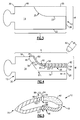
Figure 1 , there is shown a prior art technique for restoringairfoil blade 10. Airfoilblade 10 has leadingedge 18 spaced fromtrailing edge 22 andtip 26 spaced frombase 30. Length L is defined betweentip 26 andbase 30 while width W is defined between leadingedge 18 andtrailing edge 22. Generally, restoration ofairfoil blade 10 involves machining away thin and worn surfaces fromairfoil blade body 14 to formledge 23 withcurve 25, which extends fromtip 26 to one of leadingedge 18 ortrailing edge 22. Substantiallyparallel weld layers 20 are then deposited onledge 23 by welding, such as by laser powder fusion or plasma arc welding, in the direction of arrow A fromtip 26 along length L ofairfoil blade 10 to curve 25. Eachweld layer 20 starts attip 26 and ends atpoints 21 ofcurve 25. However, because welding ofweld layers 20 is stopped atpoints 21 ofcurve 25,air foil body 14 may melt or bum in the areas aroundpoints 21 due to excess heat from welding. Consequently, these areas ofairfoil blade 10 may require rework, such as additional welding and machining of these areas, which is very time-consuming. - A need therefore exists for an improved welding technique that eliminates the welding imperfection caused by localized melting at the point of contact of the weld layer with the airfoil blade body.
- A disclosed preferred method of repairing an airfoil blade involves the steps of providing an airfoil blade have a leading edge, a trailing edge, a tip and a base. A length of the airfoil blade is defined by the tip and the base and a width of the airfoil blade is defined by the leading edge and the trailing edge. A weld is made along a first direction of the length of the airfoil blade and then made in a second direction along the width of the airfoil blade to form a first weld layer. The first weld layer has a first portion extending across the length of the airfoil blade and a second portion extending across its width. A second weld layer is welded onto the first layer such that an end wall of the second weld layer abuts the second portion of the first weld layer.
- The various features and advantages of this invention will become apparent to those skilled in the art from the following detailed description. The drawings that accompany the detailed description can be briefly described as follows.
-
-
Figure 1 illustrates a prior art welding technique for restoring an airfoil blade. -
Figure 2 illustrates an exemplary welding method for restoring an airfoil blade. -
Figure 3 illustrates part of the process of the inventive technique ofFigure 2 . -
Figure 4 illustrates another step in the process of the inventive welding technique, showing a formation of a first welding layer and additional layers atop the first welding layer. -
Figure 5 illustrates a cross-sectional view of the airfoil blade ofFigure 4 , showing a thickness of the first weld layer greater than a thickness of a wall of the airfoil blade. - With reference to
Figure 2 , the exemplary method for welding facilitates avoiding the foregoing problems of the prior art by creatingfirst weld layer 34 that extends substantially acrossledge 23 andcurve 25. In other words,first weld layer 34 extends substantially across an entire length L and width W ofexemplary airfoil blade 12.Weld layers 20 are then deposited onfirst weld layer 34 such that eachweld layer 20 terminates onfirst weld layer 34 rather thanairfoil blade 12. As a result,first weld layer 34 acts as a heat buffer to absorb excess heat alongcurve 25 from subsequent welds as will be explained. - With reference to
Figure 3 , there is shownairfoil blade 12 includingairfoil blade body 14 withworn portion 35 designated by dashed lines. Through machining,worn portion 35 is removed fromairfoil blade 12 to createledge 23, includingcurve 25, atop which weld layers will be provided to restore length L and width W ofairfoil blade 12. - With reference to
Figure 4 ,first weld layer 34 is created by welding onledge 23 fromtip 26 towardsbase 30 by movingweld gun 82 in the direction of arrow A along length L ofairfoil blade 12. Atcurve 25,welding gun 82 is then moved in the transverse direction of arrow B to followcurve 25 ofledge 23 across width W ofairfoil blade 12. Weldinggun 82 continues welding across an edge, such as leadingedge 18, ofairfoil blade 12. Weldinggun 82 remains active to weld in a single passfirst weld layer 34 fromtip 26 across leadingedge 18. Although weld formation is described with reference to movingweld gun 82 with respect toairfoil blade 12, it should be appreciated by one of ordinary skill in the art thatairfoil blade 12 may be moved with respect towelding gun 82 while achieving similar results. -
First weld layer 34 includesfirst portion 38 andsecond portion 42 that together form a curve.First portion 38 extends generally along length L ofairfoil blade 12 and restoresportion 74 of length L ofairfoil blade 12.Second portion 42 extends generally along width W ofairfoil blade 12 and restores portion ofwidth 78 ofairfoil blade 12.First weld layer 34 hasfirst surface 46 in contact withairfoil blade body 14 andsecond surface 50 spaced away fromfirst surface 46. -
Figure 5 shows a cross-sectional view ofairfoil blade 12 includingfirst weld layer 34, as shown from the direction of arrow A ofFigure 4 .Airfoil blade 12 includessuction side wall 86 andpressure side wall 90 havingwall thickness 98.First weld layer 34 is formed having firstweld layer thickness 94, which is greater thanwall thickness 98 ofsuction sidewall 86 atlocation 102. As a result,first weld layer 34 is thick enough to absorb excess heat fromwelding gun 82 to facilitate avoiding localized melting or damage ofairfoil blade 12. - Following formation of
first weld layer 34,weld gun 82 is brought back totip 26 ofairfoil blade 12.Weld gun 12 then welds in the direction of arrow A to createsecond weld layer 54 so thatend wall 58 ofsecond weld layer 54 abutssecond surface 50 offirst weld layer 34. By terminatingsecond weld layer 54 atfirst weld layer 34 instead ofairfoil blade 12, excess heat may be absorbed byfirst weld layer 34 so as to facilitate avoiding blade damage. Athird weld layer 62 is also created by welding in the same manner and same direction as thesecond weld layer 54.Third weld layer 62 is formed so thatend wall 66 ofthird weld layer 62 abutssecond surface 50 offirst weld layer 34.Welding gun 82 continues to create weld layers likesecond weld layer 54 andthird weld layer 62 up to leadingedge 18 as shown inFigure 2 , with each weld layer starting attip 26 and terminating atsecond surface 50 offirst weld layer 34. Following this welding process,airfoil blade 12 may then be machined so thatairfoil blade 12 conforms to its original dimensions. - The foregoing description shall be interpreted as illustrative and not in any limiting sense. A worker of ordinary skill in the art would recognize that certain modifications would come within the scope of this invention. For that reason, the follow claims should be studied to determine the true scope and content of this invention.
Claims (14)
- A method of repairing an airfoil blade (10), comprising the steps of:(A) providing the airfoil blade (10) having a leading edge (18), a trailing edge (22), a tip (26) and a base (30), a length (L) of the airfoil blade (10) defined by the tip (26) and the base (30) and a width (W) of the airfoil blade (10) defined by the leading edge (18) and the trailing edge (22);(B) welding in a first direction (A) along the length (L) of the airfoil blade (10) and welding in a second direction (B) transverse to the first direction (A) and along the width (W) of the airfoil blade (10) to form a first weld layer (34) having a first portion (38) extending across the length (L) and a second portion (42) extending across the width (W) to restore at least a portion (74) of the length (L) and a portion (78) of the width (W) of the airfoil blade (10); and(C) welding a second weld layer (54) on to the first weld layer (34) such that an end wall (58) of the second weld layer (54) abuts the second portion (42) of the first weld layer (34).
- The method of Claim 1 including the step of:(D) welding a third weld layer (62) on to the second weld layer (54) such that an end wall (66) of the third weld layer (62) abuts the second portion (42) of the first weld layer (34).
- The method of Claim 1 or 2 wherein the first weld layer (34) has a first surface and a second surface, the first surface in contact with the airfoil blade (10) and the second surface in contact with the end wall (58) of the second weld layer (54).
- A method of repairing an airfoil blade (10), comprising the steps of:(A) providing the airfoil blade (10) having a leading edge (18), a trailing edge (22), a tip and a base (30), a length (L) of the airfoil blade (10) defined by the tip (26) and the base (30) and a width (W) of the airfoil blade (10) defined by the leading edge (18) and the trailing edge (22);(B) welding in a first direction (A) along the length (L) of the airfoil blade (10) and welding in a second direction (B) along the width (W) of the airfoil blade (10) to form a first weld layer (34) having a first portion (38) extending across the length (L) and a second portion (42) extending across the width (W) to restore at least a portion (74) of the length (L) and a portion (78) of the width (W) of the airfoil blade (10) wherein the first weld layer (34) has a first surface in contact with the airfoil blade (10) and a second surface;(C) welding a second weld layer (54) on to the first weld layer (34) such that an end wall (58) of the second weld layer (54) abuts the second portion (42) of the first weld layer (34) on the second surface of the first weld layer (34); and(D) welding a third weld layer (62) on to the second weld layer (54) such that an end wall (66) of the third weld layer (62) abuts the second portion (42) of the first weld layer (34) on the second surface of the first weld layer (34).
- The method of any preceding Claim wherein the second portion (42) extends to one of the leading edge (18) and the trailing edge (22) of the airfoil blade (10).
- The method of Claim 5 wherein the first weld layer (34) is formed across one of the leading edge (18) and the trailing edge (22) along the length (L) of airfoil blade (10).
- The method of any preceding Claim wherein the first weld layer (34) is formed in a single pass.
- The method of any preceding Claim wherein the first portion (38) and the second portion (42) of the first weld layer (34) form a curve.
- The method of any preceding Claim wherein the airfoil blade (10) has a suction side wall (86) and a pressure side wall (90), wherein the first weld layer (34) is formed having a first weld layer thickness (94) greater than a wall thickness (86) of one of the suction side wall (86) and the pressure side wall (90) at a location of the airfoil blade (10) neighboring the first weld layer (34).
- The method of any preceding Claim including the step of:removing a portion of the airfoil blade (10) prior to step (B) to accommodate the first weld layer (34).
- The method of any preceding Claim including the step of:machining a portion of at least one of the first weld layer (34) and the second weld layer (54).
- An airfoil blade (10), comprising:an airfoil body having a leading edge (18), a trailing edge (22), a tip (26) and a base (30), a length (L) of said airfoil body (10) defined by said tip (26) and said base (30) and a width (W) of said airfoil body (10) defined by said leading edge (18) and said trailing edge (22);a first weld layer (34) having a first portion (38) extending across said length (L) and a second portion (42) extending across said width (W) restoring at least a portion (74) of said length (L) and a portion (78) of said width (W) of said airfoil blade (10) wherein said first weld layer (34) has a first surface in contact with said airfoil blade (10) and a second surface spaced from said first surface; anda second weld layer (54) disposed on said first weld layer (34) such that an end wall (58) of said second weld layer (54) abuts said second portion (42) of said first weld layer (34) on said second surface of said first weld layer (34).
- An airfoil blade of Claim 12 including a third weld layer (62) disposed on to said second weld layer (54) such that an end wall (66) of said third weld layer (62) abuts said second portion (42) of said first weld layer (34) on said second surface of said first weld layer (34).
- The airfoil blade of Claim 12 or 13 wherein said first portion (38) and said second portion (42) of said first weld layer (34) forms a curve.
Applications Claiming Priority (1)
| Application Number | Priority Date | Filing Date | Title |
|---|---|---|---|
| US12/055,348 US8206121B2 (en) | 2008-03-26 | 2008-03-26 | Method of restoring an airfoil blade |
Publications (2)
| Publication Number | Publication Date |
|---|---|
| EP2105244A1 true EP2105244A1 (en) | 2009-09-30 |
| EP2105244B1 EP2105244B1 (en) | 2012-04-25 |
Family
ID=40566175
Family Applications (1)
| Application Number | Title | Priority Date | Filing Date |
|---|---|---|---|
| EP09250652A Active EP2105244B1 (en) | 2008-03-26 | 2009-03-09 | Method of restoring an airfoil blade |
Country Status (2)
| Country | Link |
|---|---|
| US (1) | US8206121B2 (en) |
| EP (1) | EP2105244B1 (en) |
Families Citing this family (11)
| Publication number | Priority date | Publication date | Assignee | Title |
|---|---|---|---|---|
| US8807955B2 (en) * | 2011-06-30 | 2014-08-19 | United Technologies Corporation | Abrasive airfoil tip |
| US9126287B2 (en) * | 2012-03-12 | 2015-09-08 | Siemens Energy, Inc. | Advanced pass progression for build-up welding |
| WO2014006467A2 (en) * | 2012-06-13 | 2014-01-09 | Pratt & Whitney Services Pte Ltd | Tip fabrication for rotor blade or stator vane airfoil |
| US9651524B2 (en) | 2013-05-31 | 2017-05-16 | Rti International Metals, Inc. | Method of ultrasonic inspection of as-cast titanium alloy articles |
| US9981349B2 (en) | 2013-05-31 | 2018-05-29 | Arconic Inc. | Titanium welding wire, ultrasonically inspectable welds and parts formed therefrom, and associated methods |
| US9359897B2 (en) * | 2014-08-15 | 2016-06-07 | Siemens Energy, Inc. | Method for building a gas turbine engine component |
| US9358643B2 (en) * | 2014-08-15 | 2016-06-07 | Siemens Energy, Inc. | Method for building a gas turbine engine component |
| DE102014220483A1 (en) * | 2014-10-09 | 2016-04-14 | Fraunhofer-Gesellschaft zur Förderung der angewandten Forschung e.V. | Construction strategy for a crown bottom of a turbine blade and turbine blade |
| WO2016073349A1 (en) * | 2014-11-05 | 2016-05-12 | Rti International Metals | Titanium welding wire, ultrasonically inspectable welds and parts therefrom, and associated methods |
| US10544698B2 (en) | 2016-06-20 | 2020-01-28 | United Technologies Corporation | Air seal abrasive coating and method |
| EP4329968A4 (en) * | 2021-04-26 | 2025-05-21 | Optomec, Inc. | Method for welding gamma strengthened superalloys and other crack-prone materials |
Citations (6)
| Publication number | Priority date | Publication date | Assignee | Title |
|---|---|---|---|---|
| EP1153699A2 (en) | 2000-05-11 | 2001-11-14 | General Electric Company | Blisk weld repair |
| JP2002066745A (en) | 2000-08-30 | 2002-03-05 | Hitachi Ltd | Gas turbine blade welding method |
| US20050029235A1 (en) * | 2003-04-12 | 2005-02-10 | Rainer Mielke | Method for the restoration of damaged areal components |
| EP1672170A1 (en) * | 2004-12-15 | 2006-06-21 | Techspace Aero S.A. | Method of repairing a bladed rotor disc |
| EP1688211A2 (en) * | 2005-02-03 | 2006-08-09 | United Technologies Corporation | Plasma arc weld repair of high nickel metal alloys |
| EP1785583A2 (en) * | 2005-10-12 | 2007-05-16 | Turbine Overhaul Services Private Limited | Blade shroud repair |
Family Cites Families (11)
| Publication number | Priority date | Publication date | Assignee | Title |
|---|---|---|---|---|
| US4726104A (en) | 1986-11-20 | 1988-02-23 | United Technologies Corporation | Methods for weld repairing hollow, air cooled turbine blades and vanes |
| US4873751A (en) | 1988-12-27 | 1989-10-17 | United Technologies Corporation | Fabrication or repair technique for integrally bladed rotor assembly |
| GB9021237D0 (en) | 1990-09-29 | 1990-11-14 | Rolls Royce Plc | A method of welding,a method of applying a metallic wear resistant coating to a metallic substrate and a method of sealing a hole in a metallic substrate |
| US5503589A (en) | 1994-06-17 | 1996-04-02 | Wikle; Kenneth C. | Apparatus and method for contour grinding gas turbine blades |
| US5822852A (en) | 1997-07-14 | 1998-10-20 | General Electric Company | Method for replacing blade tips of directionally solidified and single crystal turbine blades |
| US6179567B1 (en) | 1999-08-18 | 2001-01-30 | United Technologies Corporation | Turbomachinery blade or vane with a survivable machining datum |
| US6332272B1 (en) | 2000-01-07 | 2001-12-25 | Siemens Westinghouse Power Corporation | Method of repairing a turbine blade |
| US6364971B1 (en) | 2000-01-20 | 2002-04-02 | Electric Power Research Institute | Apparatus and method of repairing turbine blades |
| US6502303B2 (en) | 2001-05-07 | 2003-01-07 | Chromalloy Gas Turbine Corporation | Method of repairing a turbine blade tip |
| US6490791B1 (en) | 2001-06-22 | 2002-12-10 | United Technologies Corporation | Method for repairing cracks in a turbine blade root trailing edge |
| US6532656B1 (en) | 2001-10-10 | 2003-03-18 | General Electric Company | Gas turbine engine compressor blade restoration method |
-
2008
- 2008-03-26 US US12/055,348 patent/US8206121B2/en active Active
-
2009
- 2009-03-09 EP EP09250652A patent/EP2105244B1/en active Active
Patent Citations (6)
| Publication number | Priority date | Publication date | Assignee | Title |
|---|---|---|---|---|
| EP1153699A2 (en) | 2000-05-11 | 2001-11-14 | General Electric Company | Blisk weld repair |
| JP2002066745A (en) | 2000-08-30 | 2002-03-05 | Hitachi Ltd | Gas turbine blade welding method |
| US20050029235A1 (en) * | 2003-04-12 | 2005-02-10 | Rainer Mielke | Method for the restoration of damaged areal components |
| EP1672170A1 (en) * | 2004-12-15 | 2006-06-21 | Techspace Aero S.A. | Method of repairing a bladed rotor disc |
| EP1688211A2 (en) * | 2005-02-03 | 2006-08-09 | United Technologies Corporation | Plasma arc weld repair of high nickel metal alloys |
| EP1785583A2 (en) * | 2005-10-12 | 2007-05-16 | Turbine Overhaul Services Private Limited | Blade shroud repair |
Non-Patent Citations (1)
| Title |
|---|
| KHROMCHENKO F A ET AL: "TECHNOLOGY OF REPAIRING WORKING BLADES OF STEAM TURBINES. PART 1. REPAIR BY THE METHOD OF DEPOSITION OF HIGH-CR ALLOYS", WELDING INTERNATIONAL, TAYLOR & FRANCIS, ABINGDON, GB, vol. 13, no. 5, 1 January 1999 (1999-01-01), pages 405 - 408, XP000824280, ISSN: 0950-7116 * |
Also Published As
| Publication number | Publication date |
|---|---|
| US8206121B2 (en) | 2012-06-26 |
| EP2105244B1 (en) | 2012-04-25 |
| US20090246031A1 (en) | 2009-10-01 |
Similar Documents
| Publication | Publication Date | Title |
|---|---|---|
| EP2105244B1 (en) | Method of restoring an airfoil blade | |
| US8156649B2 (en) | Gas turbine hot gas component repair method | |
| US7509736B2 (en) | Process for repairing metallic pieces especially turbine blades of a gas turbine motor | |
| US9869189B2 (en) | Method for friction welding a blade onto a turbine engine rotor disc; corresponding integral blade disc | |
| US10722989B2 (en) | Turbine rotor disc repairing method | |
| EP3466602B1 (en) | Method for forming an article | |
| JP2008045541A (en) | Method of repairing shroud of turbine blades | |
| CN104718348B (en) | Welding method of corrosion-resistant metal material and turbine blade | |
| EP2872286A1 (en) | Method for repairing a single crystal turbine blade | |
| EP2823149B1 (en) | Turbine diaphragm airfoil, diaphragm assembly, and method of repair | |
| JP5449610B2 (en) | Method of welding erosion resistant metal material and turbine blade | |
| CN107735207A (en) | Method and apparatus for producing metal blank | |
| JP5372436B2 (en) | Use of active flux for TIG welding of metal parts | |
| CN114728317A (en) | Grooving method of steel strip, cold rolling method and manufacturing method of cold rolled steel strip | |
| WO2019164488A1 (en) | Welding tool and methodology for forming welding joints free of notch-induced cracking | |
| JP4202107B2 (en) | Welded joint structure | |
| WO2021034930A1 (en) | Pre-weld modification technique for a custom welded blank | |
| JPS63295802A (en) | Repairing of nozzle plate of steam turbine | |
| JP2012229639A (en) | Method for repairing turbine high-temperature component, gas turbine moving blade and gas turbine | |
| CN116329713B (en) | A method for repairing surface cracks in roll welds of titanium alloy double-layer thin-walled parts | |
| RU2575894C2 (en) | Method of manufacturing of metal reinforcement element |
Legal Events
| Date | Code | Title | Description |
|---|---|---|---|
| PUAI | Public reference made under article 153(3) epc to a published international application that has entered the european phase |
Free format text: ORIGINAL CODE: 0009012 |
|
| 17P | Request for examination filed |
Effective date: 20090817 |
|
| AK | Designated contracting states |
Kind code of ref document: A1 Designated state(s): AT BE BG CH CY CZ DE DK EE ES FI FR GB GR HR HU IE IS IT LI LT LU LV MC MK MT NL NO PL PT RO SE SI SK TR |
|
| AX | Request for extension of the european patent |
Extension state: AL BA RS |
|
| 17Q | First examination report despatched |
Effective date: 20090930 |
|
| AKX | Designation fees paid |
Designated state(s): DE GB |
|
| GRAP | Despatch of communication of intention to grant a patent |
Free format text: ORIGINAL CODE: EPIDOSNIGR1 |
|
| GRAS | Grant fee paid |
Free format text: ORIGINAL CODE: EPIDOSNIGR3 |
|
| GRAA | (expected) grant |
Free format text: ORIGINAL CODE: 0009210 |
|
| AK | Designated contracting states |
Kind code of ref document: B1 Designated state(s): DE GB |
|
| REG | Reference to a national code |
Ref country code: GB Ref legal event code: FG4D |
|
| REG | Reference to a national code |
Ref country code: DE Ref legal event code: R096 Ref document number: 602009006514 Country of ref document: DE Effective date: 20120621 |
|
| PLBI | Opposition filed |
Free format text: ORIGINAL CODE: 0009260 |
|
| 26 | Opposition filed |
Opponent name: SIEMENS AKTIENGESELLSCHAFT Effective date: 20120801 |
|
| REG | Reference to a national code |
Ref country code: DE Ref legal event code: R026 Ref document number: 602009006514 Country of ref document: DE Effective date: 20120801 |
|
| PLAX | Notice of opposition and request to file observation + time limit sent |
Free format text: ORIGINAL CODE: EPIDOSNOBS2 |
|
| PLBB | Reply of patent proprietor to notice(s) of opposition received |
Free format text: ORIGINAL CODE: EPIDOSNOBS3 |
|
| PLAB | Opposition data, opponent's data or that of the opponent's representative modified |
Free format text: ORIGINAL CODE: 0009299OPPO |
|
| R26 | Opposition filed (corrected) |
Opponent name: SIEMENS AKTIENGESELLSCHAFT Effective date: 20120801 |
|
| PLCK | Communication despatched that opposition was rejected |
Free format text: ORIGINAL CODE: EPIDOSNREJ1 |
|
| APBM | Appeal reference recorded |
Free format text: ORIGINAL CODE: EPIDOSNREFNO |
|
| APBP | Date of receipt of notice of appeal recorded |
Free format text: ORIGINAL CODE: EPIDOSNNOA2O |
|
| APAH | Appeal reference modified |
Free format text: ORIGINAL CODE: EPIDOSCREFNO |
|
| APBQ | Date of receipt of statement of grounds of appeal recorded |
Free format text: ORIGINAL CODE: EPIDOSNNOA3O |
|
| APAH | Appeal reference modified |
Free format text: ORIGINAL CODE: EPIDOSCREFNO |
|
| APAH | Appeal reference modified |
Free format text: ORIGINAL CODE: EPIDOSCREFNO |
|
| RAP2 | Party data changed (patent owner data changed or rights of a patent transferred) |
Owner name: UNITED TECHNOLOGIES CORPORATION |
|
| REG | Reference to a national code |
Ref country code: DE Ref legal event code: R082 Ref document number: 602009006514 Country of ref document: DE Representative=s name: SCHMITT-NILSON SCHRAUD WAIBEL WOHLFROM PATENTA, DE |
|
| REG | Reference to a national code |
Ref country code: DE Ref legal event code: R082 Ref document number: 602009006514 Country of ref document: DE Representative=s name: SCHMITT-NILSON SCHRAUD WAIBEL WOHLFROM PATENTA, DE Ref country code: DE Ref legal event code: R081 Ref document number: 602009006514 Country of ref document: DE Owner name: UNITED TECHNOLOGIES CORP. (N.D.GES.D. STAATES , US Free format text: FORMER OWNER: UNITED TECHNOLOGIES CORPORATION, HARTFORD, CONN., US |
|
| PLAB | Opposition data, opponent's data or that of the opponent's representative modified |
Free format text: ORIGINAL CODE: 0009299OPPO |
|
| R26 | Opposition filed (corrected) |
Opponent name: SIEMENS AKTIENGESELLSCHAFT Effective date: 20120801 |
|
| APBU | Appeal procedure closed |
Free format text: ORIGINAL CODE: EPIDOSNNOA9O |
|
| REG | Reference to a national code |
Ref country code: DE Ref legal event code: R100 Ref document number: 602009006514 Country of ref document: DE |
|
| PLBN | Opposition rejected |
Free format text: ORIGINAL CODE: 0009273 |
|
| STAA | Information on the status of an ep patent application or granted ep patent |
Free format text: STATUS: OPPOSITION REJECTED |
|
| 27O | Opposition rejected |
Effective date: 20180706 |
|
| REG | Reference to a national code |
Ref country code: DE Ref legal event code: R081 Ref document number: 602009006514 Country of ref document: DE Owner name: RAYTHEON TECHNOLOGIES CORPORATION (N.D.GES.D.S, US Free format text: FORMER OWNER: UNITED TECHNOLOGIES CORP. (N.D.GES.D. STAATES DELAWARE), FARMINGTON, CONN., US Ref country code: DE Ref legal event code: R081 Ref document number: 602009006514 Country of ref document: DE Owner name: RTX CORPORATION (N.D.GES.D. STAATES DELAWARE),, US Free format text: FORMER OWNER: UNITED TECHNOLOGIES CORP. (N.D.GES.D. STAATES DELAWARE), FARMINGTON, CONN., US |
|
| P01 | Opt-out of the competence of the unified patent court (upc) registered |
Effective date: 20230519 |
|
| REG | Reference to a national code |
Ref country code: DE Ref legal event code: R081 Ref document number: 602009006514 Country of ref document: DE Owner name: RTX CORPORATION (N.D.GES.D. STAATES DELAWARE),, US Free format text: FORMER OWNER: RAYTHEON TECHNOLOGIES CORPORATION (N.D.GES.D.STAATES DELAWARE), ARLINGTON, VA, US |
|
| PGFP | Annual fee paid to national office [announced via postgrant information from national office to epo] |
Ref country code: GB Payment date: 20260220 Year of fee payment: 18 |
|
| PGFP | Annual fee paid to national office [announced via postgrant information from national office to epo] |
Ref country code: DE Payment date: 20260219 Year of fee payment: 18 |