EP2105151A1 - Membrane pump with ventilation valve - Google Patents
Membrane pump with ventilation valve Download PDFInfo
- Publication number
- EP2105151A1 EP2105151A1 EP09007901A EP09007901A EP2105151A1 EP 2105151 A1 EP2105151 A1 EP 2105151A1 EP 09007901 A EP09007901 A EP 09007901A EP 09007901 A EP09007901 A EP 09007901A EP 2105151 A1 EP2105151 A1 EP 2105151A1
- Authority
- EP
- European Patent Office
- Prior art keywords
- membrane
- suction pump
- pump according
- vent
- venting
- Prior art date
- Legal status (The legal status is an assumption and is not a legal conclusion. Google has not performed a legal analysis and makes no representation as to the accuracy of the status listed.)
- Granted
Links
- 239000012528 membrane Substances 0.000 title claims abstract description 106
- 238000009423 ventilation Methods 0.000 title claims description 5
- 238000013022 venting Methods 0.000 claims description 64
- 229920001296 polysiloxane Polymers 0.000 claims description 5
- 238000000034 method Methods 0.000 abstract description 9
- 238000007789 sealing Methods 0.000 description 14
- 210000000481 breast Anatomy 0.000 description 12
- 238000005086 pumping Methods 0.000 description 7
- 239000000463 material Substances 0.000 description 6
- 235000013336 milk Nutrition 0.000 description 6
- 239000008267 milk Substances 0.000 description 6
- 210000004080 milk Anatomy 0.000 description 6
- 235000020256 human milk Nutrition 0.000 description 4
- 210000001124 body fluid Anatomy 0.000 description 3
- 239000010839 body fluid Substances 0.000 description 3
- 210000004251 human milk Anatomy 0.000 description 3
- 239000007788 liquid Substances 0.000 description 3
- 125000006850 spacer group Chemical group 0.000 description 3
- 229930040373 Paraformaldehyde Natural products 0.000 description 2
- 210000000038 chest Anatomy 0.000 description 2
- 238000004140 cleaning Methods 0.000 description 2
- 238000004519 manufacturing process Methods 0.000 description 2
- 229920006324 polyoxymethylene Polymers 0.000 description 2
- 230000033764 rhythmic process Effects 0.000 description 2
- 230000008719 thickening Effects 0.000 description 2
- 238000004026 adhesive bonding Methods 0.000 description 1
- 238000007664 blowing Methods 0.000 description 1
- 238000010276 construction Methods 0.000 description 1
- 230000008878 coupling Effects 0.000 description 1
- 238000010168 coupling process Methods 0.000 description 1
- 238000005859 coupling reaction Methods 0.000 description 1
- 125000004122 cyclic group Chemical group 0.000 description 1
- 230000001419 dependent effect Effects 0.000 description 1
- 230000003670 easy-to-clean Effects 0.000 description 1
- 238000004146 energy storage Methods 0.000 description 1
- 238000009413 insulation Methods 0.000 description 1
- 230000007257 malfunction Effects 0.000 description 1
- 230000002093 peripheral effect Effects 0.000 description 1
- -1 polyoxymethylene Polymers 0.000 description 1
- 239000007787 solid Substances 0.000 description 1
- 230000000638 stimulation Effects 0.000 description 1
- XLYOFNOQVPJJNP-UHFFFAOYSA-N water Substances O XLYOFNOQVPJJNP-UHFFFAOYSA-N 0.000 description 1
Images


Classifications
-
- A—HUMAN NECESSITIES
- A61—MEDICAL OR VETERINARY SCIENCE; HYGIENE
- A61M—DEVICES FOR INTRODUCING MEDIA INTO, OR ONTO, THE BODY; DEVICES FOR TRANSDUCING BODY MEDIA OR FOR TAKING MEDIA FROM THE BODY; DEVICES FOR PRODUCING OR ENDING SLEEP OR STUPOR
- A61M1/00—Suction or pumping devices for medical purposes; Devices for carrying-off, for treatment of, or for carrying-over, body-liquids; Drainage systems
- A61M1/06—Milking pumps
- A61M1/062—Pump accessories
- A61M1/064—Suction cups
- A61M1/066—Inserts therefor
-
- A—HUMAN NECESSITIES
- A61—MEDICAL OR VETERINARY SCIENCE; HYGIENE
- A61M—DEVICES FOR INTRODUCING MEDIA INTO, OR ONTO, THE BODY; DEVICES FOR TRANSDUCING BODY MEDIA OR FOR TAKING MEDIA FROM THE BODY; DEVICES FOR PRODUCING OR ENDING SLEEP OR STUPOR
- A61M1/00—Suction or pumping devices for medical purposes; Devices for carrying-off, for treatment of, or for carrying-over, body-liquids; Drainage systems
- A61M1/80—Suction pumps
- A61M1/82—Membrane pumps, e.g. bulbs
-
- F—MECHANICAL ENGINEERING; LIGHTING; HEATING; WEAPONS; BLASTING
- F04—POSITIVE - DISPLACEMENT MACHINES FOR LIQUIDS; PUMPS FOR LIQUIDS OR ELASTIC FLUIDS
- F04B—POSITIVE-DISPLACEMENT MACHINES FOR LIQUIDS; PUMPS
- F04B43/00—Machines, pumps, or pumping installations having flexible working members
-
- F—MECHANICAL ENGINEERING; LIGHTING; HEATING; WEAPONS; BLASTING
- F04—POSITIVE - DISPLACEMENT MACHINES FOR LIQUIDS; PUMPS FOR LIQUIDS OR ELASTIC FLUIDS
- F04B—POSITIVE-DISPLACEMENT MACHINES FOR LIQUIDS; PUMPS
- F04B43/00—Machines, pumps, or pumping installations having flexible working members
- F04B43/0009—Special features
- F04B43/0054—Special features particularities of the flexible members
-
- F—MECHANICAL ENGINEERING; LIGHTING; HEATING; WEAPONS; BLASTING
- F04—POSITIVE - DISPLACEMENT MACHINES FOR LIQUIDS; PUMPS FOR LIQUIDS OR ELASTIC FLUIDS
- F04B—POSITIVE-DISPLACEMENT MACHINES FOR LIQUIDS; PUMPS
- F04B45/00—Pumps or pumping installations having flexible working members and specially adapted for elastic fluids
- F04B45/04—Pumps or pumping installations having flexible working members and specially adapted for elastic fluids having plate-like flexible members, e.g. diaphragms
- F04B45/047—Pumps having electric drive
-
- F—MECHANICAL ENGINEERING; LIGHTING; HEATING; WEAPONS; BLASTING
- F04—POSITIVE - DISPLACEMENT MACHINES FOR LIQUIDS; PUMPS FOR LIQUIDS OR ELASTIC FLUIDS
- F04B—POSITIVE-DISPLACEMENT MACHINES FOR LIQUIDS; PUMPS
- F04B49/00—Control, e.g. of pump delivery, or pump pressure of, or safety measures for, machines, pumps, or pumping installations, not otherwise provided for, or of interest apart from, groups F04B1/00 - F04B47/00
- F04B49/02—Stopping, starting, unloading or idling control
- F04B49/03—Stopping, starting, unloading or idling control by means of valves
-
- F—MECHANICAL ENGINEERING; LIGHTING; HEATING; WEAPONS; BLASTING
- F04—POSITIVE - DISPLACEMENT MACHINES FOR LIQUIDS; PUMPS FOR LIQUIDS OR ELASTIC FLUIDS
- F04B—POSITIVE-DISPLACEMENT MACHINES FOR LIQUIDS; PUMPS
- F04B49/00—Control, e.g. of pump delivery, or pump pressure of, or safety measures for, machines, pumps, or pumping installations, not otherwise provided for, or of interest apart from, groups F04B1/00 - F04B47/00
- F04B49/10—Other safety measures
-
- A—HUMAN NECESSITIES
- A61—MEDICAL OR VETERINARY SCIENCE; HYGIENE
- A61M—DEVICES FOR INTRODUCING MEDIA INTO, OR ONTO, THE BODY; DEVICES FOR TRANSDUCING BODY MEDIA OR FOR TAKING MEDIA FROM THE BODY; DEVICES FOR PRODUCING OR ENDING SLEEP OR STUPOR
- A61M1/00—Suction or pumping devices for medical purposes; Devices for carrying-off, for treatment of, or for carrying-over, body-liquids; Drainage systems
- A61M1/80—Suction pumps
- A61M1/802—Suction pumps by vacuum created above a liquid flowing from a closed container
-
- A—HUMAN NECESSITIES
- A61—MEDICAL OR VETERINARY SCIENCE; HYGIENE
- A61M—DEVICES FOR INTRODUCING MEDIA INTO, OR ONTO, THE BODY; DEVICES FOR TRANSDUCING BODY MEDIA OR FOR TAKING MEDIA FROM THE BODY; DEVICES FOR PRODUCING OR ENDING SLEEP OR STUPOR
- A61M2205/00—General characteristics of the apparatus
- A61M2205/33—Controlling, regulating or measuring
- A61M2205/3331—Pressure; Flow
- A61M2205/3337—Controlling, regulating pressure or flow by means of a valve by-passing a pump
-
- A—HUMAN NECESSITIES
- A61—MEDICAL OR VETERINARY SCIENCE; HYGIENE
- A61M—DEVICES FOR INTRODUCING MEDIA INTO, OR ONTO, THE BODY; DEVICES FOR TRANSDUCING BODY MEDIA OR FOR TAKING MEDIA FROM THE BODY; DEVICES FOR PRODUCING OR ENDING SLEEP OR STUPOR
- A61M2205/00—General characteristics of the apparatus
- A61M2205/42—Reducing noise
-
- A—HUMAN NECESSITIES
- A61—MEDICAL OR VETERINARY SCIENCE; HYGIENE
- A61M—DEVICES FOR INTRODUCING MEDIA INTO, OR ONTO, THE BODY; DEVICES FOR TRANSDUCING BODY MEDIA OR FOR TAKING MEDIA FROM THE BODY; DEVICES FOR PRODUCING OR ENDING SLEEP OR STUPOR
- A61M2205/00—General characteristics of the apparatus
- A61M2205/82—Internal energy supply devices
- A61M2205/8206—Internal energy supply devices battery-operated
-
- F—MECHANICAL ENGINEERING; LIGHTING; HEATING; WEAPONS; BLASTING
- F16—ENGINEERING ELEMENTS AND UNITS; GENERAL MEASURES FOR PRODUCING AND MAINTAINING EFFECTIVE FUNCTIONING OF MACHINES OR INSTALLATIONS; THERMAL INSULATION IN GENERAL
- F16K—VALVES; TAPS; COCKS; ACTUATING-FLOATS; DEVICES FOR VENTING OR AERATING
- F16K31/00—Actuating devices; Operating means; Releasing devices
- F16K31/02—Actuating devices; Operating means; Releasing devices electric; magnetic
- F16K31/06—Actuating devices; Operating means; Releasing devices electric; magnetic using a magnet, e.g. diaphragm valves, cutting off by means of a liquid
- F16K31/0644—One-way valve
- F16K31/0672—One-way valve the valve member being a diaphragm
Definitions
- the invention relates to a suction pump with a vent valve according to the preamble of patent claim 1.
- Suction pumps are known for a wide variety of applications. However, they can preferably be used in breast pump devices for pumping out breast milk or as drainage pumps for aspirating body fluids.
- suction pumps in closed systems, which always convert the same air in the pump room.
- open pump systems with a vent valve, which can be opened cyclically via an electromagnet.
- suction pumps especially when used as breast pumps, are relatively high. So they should be as powerful as possible and still be relatively small. In particular, in their application as breast pumps they should also be as maintenance-free and easy to clean.
- the suction pump according to the invention has a venting valve with a venting membrane, wherein this venting membrane and a vacuum membrane used for generating the vacuum are formed integrally in the form of a common membrane plate.
- venting valve and the vacuum membrane are arranged on the same plate, these elements can be produced less expensively and mounted more easily.
- the pump has an upper housing part, a middle housing part and a lower housing part, wherein a membrane plate or a valve plate is arranged between the housing parts.
- a membrane plate or a valve plate is arranged between the housing parts.
- Another advantage of this multi-level modular design is that the pump can be cleaned by simply rinsing it without having to disassemble it into its component parts. Thanks to the outgoing exhaust, a sponge is unnecessary. Such sponges are used in the prior art to absorb milk sucked into the pump and also to dampen the sound. However, they require space in the pump and tend to undesirable odor.
- a preferred embodiment and a preferred method for actuating the suction pump allow the smallest possible design of the pump, while still allowing short pump cycles.
- a vent body which closes a vent opening of the vent valve, first only partially raised. As a result, a smaller force is required than when the entire vent opening is released in a single step.
- the means used for the actuation, in particular the raising of the vent body can thus have a smaller power and can therefore be made smaller. If an electromagnet is used as such means, then a relatively low-performance copy can be used. This is because the electromagnet when applying or lifting the breather body can first apply less force than at the end of the movement. However, this lower power available at the beginning is sufficient to expose a smaller opening. It can thus use a relatively small and therefore also cost-effective electromagnet.
- the vent can be made relatively large. This ensures a rapid cancellation of the negative pressure and thus the desired functionality of the pump.
- the pump easily reaches 120 cycles per minute. However, it can also be optimally operated at a cycle number of 50-72 cycles per minute. One number of cycles is particularly suitable for stimulation, the other for the expression of breast milk.
- the vent body is the membrane.
- the lifting of their edge area is facilitated when the raised edge region has a smaller thickness than the remaining membrane.
- the vent opening is polygonal, in particular quadrangular or triangular, formed.
- the membrane is preferably polygonal, preferably square or triangular, formed.
- a connecting pin can be attached to her or integrally formed on her, which is connected to an armature of the solenoid.
- this connecting pin is located in the edge region of the membrane, which covers the vent opening.
- the membrane can also be formed with a raised flange, wherein the connecting pin is not arranged above the vent opening but at this raised flange.
- connecting pin is designed to be movable with respect to the membrane, manufacturing or assembly-related tolerances can be bridged. Angular errors of the electromagnet can also be compensated. Good results have been achieved with a connecting pin, which is integrally formed on a venting membrane made of silicone and which has sufficient stiffness by appropriate material thickening. It can be articulated. In a simple embodiment, however, the elasticity of the material of the connecting pin is sufficient to make it movable about its attachment point.
- venting membrane which can be actuated in an edge region has the advantage that it ensures the tightness and therefore, in particular when used in a breastpump, can not have a leak for the pumped milk.
- the suction pump to a safety valve wherein the suction pump not by liquid, especially milk, which in the pump has been sucked in and has started there, can be inactivated.
- This suction pump has a safety valve with a first stage, which opens at a first negative pressure, and with a second stage, which opens at a second negative pressure.
- the first negative pressure is lower in absolute terms than the second.
- This two-stage design of the safety valve prevents milk from reaching the second stage. Since the first stage already opens with a very small deviation of the ideal negative pressure, it will still open in the case of a gluing at a higher amount of negative pressure, so in an emergency.
- the second valve prevents the safety valve from opening when there is too little deviation, but it reliably opens in the event of an emergency.
- the suction pump according to a preferred embodiment can thus reduce the vacuum without too much effort in a relatively short time.
- the inventive pump is suitable for a variety of applications. In particular, it is suitable as a breast pump for aspirating breast milk and as a drainage pump for aspirating body fluids.
- the inventive pump unit is particularly suitable for use in a portable breast pump, as in particular in the WO 2004/069306 (Application No. PCT / CH 2004/000061 is described.
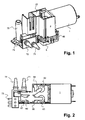
- FIG. 1 is a suction pump according to the invention shown, as suitable in particular for a breast pump device for pumping human breast milk is.
- the pump is also suitable for other applications, for example for drainage pumps for the suction of body fluids.
- This unit is usually arranged in an outer housing. This outer housing and the necessary for the operation of the pump electronics and any energy storage, such as an accumulator or a battery are not shown.
- the pump is extremely compact.
- One of its largest elements is an electric motor 1.
- it has an upper, a middle and a lower housing part 2, 4, 6, which are plugged together.
- a connection part 7 is present, which is part of these housing parts or, as is the case here, also plugged together with these.
- connection part 7 there is at least one breast tube-side connecting piece 70, on which a connecting tube can be attached to a breast shield. Furthermore, the connecting part 7 has an exhaust 71. This exhaust 71 leads out of the outer housing. Furthermore, a venting channel 72, which protrudes from the outer housing, and spacers 73 are also provided. The spacers 73 support the pump unit from an outer housing, so that vibrations can not be transmitted and a sufficient sound insulation is ensured.
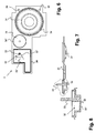
- FIG. 2 can be seen how the individual ports 70, 71, 72 are connected via individual channels with the individual areas of the pump.
- FIG. 3 shown longitudinal section through the pump, now without motor 1, shows that the pump is divided despite its compactness in three clearly distinguishable functional areas: a pumping unit P, a venting unit V and an interposed safety unit S.
- the construction of the pump can be in the synopsis of the Figures 3 and 4 best recognized.
- the pump unit P has a vacuum membrane 31 and inlet and outlet control valves 51, 52 which, with inlet and outlet openings 62, 63 or with a pump chamber opening 43 ', create a connection between a pump chamber 43 and a vacuum channel 69.
- the vacuum membrane 31 is connected via a connecting rod 11, coupling piece 12, such as a ball bearing, and eccentric 13 with a drive shaft 10 of the electric motor 1 and can be raised by means of this motor 1 according to a predetermined or freely selectable via a controller rhythm or pump curve and lower.
- the venting unit V has a venting valve with a venting membrane 32 and a venting opening in the form of a venting membrane seat 44 which can be sealed tightly therefrom.
- the chamber 44 'surrounding the vent membrane seat 44 is connected to the vent passage 72 via a vent port 45.
- the vent membrane seat 44 is down, i. formed open on the vent membrane 32 side facing away from and connects to a first vent opening 54 of the valve plate 5 and a second vent opening 67 of the lower housing part 6 at. This second vent opening 67 is connected via the vacuum channel 69 with a safety valve chamber 68 and the inlet opening 62.
- the venting membrane 32 is connected via a connecting pin 33 with an armature 80 of a lifting or electromagnet 8.
- the solenoid 8 raises the venting membrane 32 and thus exposes the vent membrane seat 44.
- air passes through the ventilation channel 72 and the first and second vent openings 54, 67 in the vacuum channel 69 and the negative pressure prevailing therein is reduced.
- This raising and lowering of the venting membrane 32 also takes place according to a predetermined or freely selectable via a control function, which is coordinated with the movement of the vacuum membrane 31.
- the movements of the vacuum membrane 31 and the venting membrane 32 are coordinated so that a pumping curve is obtained, as in WO 01/47577 described and which is adapted to the needs of mother and child or imitates the natural suckling rhythm of an infant.
- the unit works in all situations, ie lying on a table or standing or during a transport.
- the vacuum created is largely independent of how the unit is arranged relatively in space.
- the safety unit S has a safety valve. This safety valve prevents in case of malfunction or failure of the control electronics, which coordinates the movement of the vacuum membrane 31 and the venting membrane 32 with each other, that the amount of prevailing in the pump vacuum is too large and the mother's breast is injured.
- the security unit S is formed in two stages according to the invention.
- the first stage consists of a first safety diaphragm 55 and a hemispherical safety valve closure 46 with a small lateral opening 46 'which presses on the first safety diaphragm 55.
- This first stage opens already at a low vacuum of about 120mmHg.
- the second stage has a second safety diaphragm 35, which is closed by means of an adjusting screw 9. Its limit, at which it opens, can be changed by adjusting the adjusting screw 9. According to the invention it opens at a higher negative pressure than the first stage, for example at about 290 mmHg.
- milk or another aspirated liquid undesirably enters the pump, it settles in the area of the first stage and can not reach the second stage via the intervening chamber. It can thus bond at most the first safety membrane 55. This may no longer open at the pre-set value in the bonded state, but still early enough to allow relief.
- the second diaphragm only opens when the limit value is really exceeded and the pump has to be relieved. Since the second stage can not be polluted, it always opens reliably.
- FIG. 4 The individual parts of the pump are in FIG. 4 best recognizable.
- This exploded view shows that the pump is divided into several levels I, II, III, IV, V, wherein in each case parts of the pumping unit P, the safety unit S and the ventilation unit V are arranged on common planes.
- a first level I which usually, but not necessarily, forms the uppermost level, has the upper housing part 2, the already mentioned motor 1 and the electromagnet 8.
- the motor 1 is attached via fastening screws 21 to a motor plate 20 of the upper housing part 2.
- the motor can be screwed to the motor plate 20 and is also plugged into the pump unit.
- the housing part 2 has a connecting-rod chamber 23 which serves to receive the connecting rod 11, the ball bearing 12 connected thereto and an eccentric with counterweight 13.
- the counterweight 13 does not necessarily have to be present.
- the upper housing part 2 also has a separate from the connecting rod 23 magnetic chamber 24, in which the electromagnet 8 is fixed. At its lower end, the upper housing part 2 upper Einrastbügel 22 which project downwards.
- the adjusting screw 9 for the second stage of the safety valve is also still adjustable.
- the second level II is defined by a membrane plate 3, which extends at least approximately over the entire base surface of the upper housing part 2 and thus of the pump unit.
- the membrane plate 3 is made of a flexible material, in particular made of silicone, and is relatively thin. It has centering holes 30 in its edge regions and upper and lower sealing lips 34, 34 ', 34 ", which ensure an air-tight and liquid-tight connection with the upper housing part 2 or with the middle housing part 4.
- the lower sealing lips are in FIG. 7 recognizable.
- the membrane plate 3 comprises the venting membrane 32, which is triangular in shape.
- the venting membrane 32 has, as in FIG. 6 is recognizable, a triangular basic shape.
- This triangle is subdivided into two subregions, wherein a first subregion 32 'in turn forms a triangle and the second subregion 32 "is formed by the remaining part of the membrane and thus has a trapezoidal shape
- a first corner of the first subregion 32' coincides with a corner an opposite side of the first portion 32 'is parallel to an opposite side of the venting membrane 32 and the two other sides of the triangle of the first portion 32' extend congruent with the sides of the triangle of the venting membrane 32.
- the triangular first portion 32nd ' has a smaller thickness than the second Subarea 32 ", as in the FIGS. 7 and 8 is recognizable.
- the connecting pin 33 At the free corner of the first portion 32 'of the connecting pin 33 is formed. He stands, as also in the FIGS. 7 and 8 can be seen, at least approximately perpendicular to the membrane plane upwards and he is firmly connected to the armature 80.
- the venting membrane 32 is surrounded by a first sealing lip 34.
- the membrane plate 3 further comprises the vacuum membrane 31, which is connected to the connecting rod 11.
- the connecting rod 11 may be integrally formed by thickening of the material on the vacuum membrane 31 or consist of a two-component material. But it can also be made separately and connected to the membrane 31 during assembly.
- the vacuum membrane is sealed by means of a second sealing lip 34 'with respect to the upper and middle housing part 2, 4.
- the membrane plate 3 still has the second diaphragm 35 of the safety valve. This points out how this works best in FIG. 7 is visible, a V-shaped downwardly widening opening and by means of a surrounding third sealing lip 34 "relative to the upper and middle housing part 2, 4 sealingly delimited.
- the third level III is formed by the middle housing part 4.
- This is like the upper and lower housing part 2, 6 preferably made of a solid plastic material, for example POM (polyoxymethylene).
- the middle housing part 4 is designed plate-shaped and has a flat top and a flat bottom surface. At its lateral end faces it is provided with upwardly and downwardly oriented detent pawls 40, 41, the upper detent pawls 40 engaging in the upper latching brackets 22 of the upper housing part 2 and the lower detent pawls 41 in lower latching hooks 60 of the lower housing part 6. Furthermore, centering holes 42 are still present, which are aligned with the centering holes 30 of the membrane plate 3.
- two downwardly closed recesses with small lateral connection openings are present.
- One of these recesses forms the vacuum membrane 43 for the vacuum membrane and thus defines the pumping chamber.
- a second of these recesses forms a security lock 46 of the first security level.
- the chamber 44 'with the membrane seat 44 disposed therein for the venting membrane 32 is present. This seat 44 is triangular in this example.
- the chamber 44 ' is a recessed, H-shaped trough, wherein trough is connected to the vent port 45.
- the fourth level IV in turn consists of a flexible plate, preferably made of silicone. It is formed by a valve plate 5. This also has centering holes 50, wherein at least a few of these centering holes 50 are aligned with the centering holes of the central housing part 4 and the membrane plate 3.
- the valve plate 5 has a first control flap 51, which forms an inlet for the vacuum chamber. It also has a second control flap 52, which forms an outlet for the vacuum chamber. Of the second control valve 52 performs a double sealing lip 53 away, which surrounds a arranged in the lower housing part 6, upwardly open connecting channel 64 surrounds and seals it upwards.
- the first diaphragm 55 of the safety valve is further formed. Furthermore, the first vent opening 54 is present, which ensures a connection between the vent membrane seat 44 and a second vent opening 67, which is arranged in the lower housing part 6.
- the individual elements of the valve plate 5 are in turn provided with lower and upper sealing lips to seal against the middle and lower housing part 4, 6. Preferably, all elements of the valve plate 5 are integrally manufactured together with this.
- the fifth level V comprises the lower housing part 6 and the connecting part 7. These two parts may be formed by an integral common part or they may, as shown here, be coupled to one another via plug connections.
- the lower housing part 6 is in FIG. 4 and in a different perspective in FIG. 5 shown. It is also plate-shaped, with its underside forming the bottom of the pump unit. Laterally, the lower snap-in straps 60 project upwards so that the lower latching pawls 41 of the middle housing part 4 can latch into them. Further, centering pins 61 are present, which also project upwardly and which can be guided through the centering holes 30, 42, 50 of the membrane plate 3, the middle housing part 4 and the valve plate 5. These centering pins and centering holes facilitate the stacking of the individual levels and thus enable fast assembly.
- the lower housing part 6 also has a first circular recess with a central elevation, which forms an inlet opening 62.
- a second circular recess forms an outlet opening 63.
- This inlet opening 62 is connected to the vacuum channel 69 extending in the interior of the lower housing part 6.
- This channel 69 first penetrates the safety valve opening 68, which is also formed as a trough and over which the safety diaphragm 55 of the first stage is arranged.
- the connecting channel 64 which is open at the top and sealed by the sealing lip 53 in the lower housing part 6, opens the outlet opening 63.
- This connecting channel 64 is connected to the second vent opening 67 present in the lower housing part 6.
- the connecting channel 64 terminates in an exhaust port 66, which is inserted into the exhaust 71.
- the second vent opening 67 leads to a chest hood-side connecting part 65, which is connected to the chest hood-side connecting piece 70.
- This structure allows easy cleaning of the pump. Should milk or other aspirated liquid enter the pump, it can simply be flushed with water or air by squeezing or blowing the cleaning medium through the breast pump side port 70, returning the pump through the vent passage 72 and the exhaust 71 leaves.
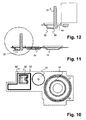
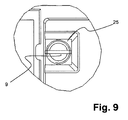
- FIG. 9 is a partial view from above in the upper housing part 2 shown.
- the adjusting screw 9 of the safety valve S is formed with a round cross-section, but screwed in a square threaded opening 25. As a result, a sufficiently large air passage is always guaranteed.
- the venting membrane 32 is not triangular but quadrangular. However, it may also have hexagonal or octagonal or any polygonal shape. However, it has been shown in practice that the quadrangular variant closes and opens more reliably compared to the triangular shape.
- the venting membrane is divided into a thick and a thin portion 32 ', 32 ", wherein the connecting pin 33 is disposed on the thin portion 32' It is no longer fixed in a corner, but approximately in the middle of this longitudinal side, as shown in FIG FIG. 10 is recognizable.
- the connecting pin 33 is preferably located just above the corner of the triangular hole 44.
- the inventive suction pump thus has several advantages. It offers great functionality in a small space and is also inexpensive to produce and easy to assemble.
- the invention also relates to the following:
- a method for operating a suction pump, in particular a diaphragm pump for generating a vacuum wherein the suction pump is a vent valve with a Breather body (32) which at cyclic intervals a vent opening (44, 54, 67) releases and closes again sealing, characterized in that the vent body (32) is raised so that it the vent opening (44, 54, 67) first only partially releases.
- This method has the following variants and combinations of variants: This method, wherein the vent body (32) is first removed at an edge region of the vent opening (44, 54, 67).
- This method wherein first a first portion of the vent body (32) is raised to release a first vent passage and then a second portion of the vent body (32) is raised to release a second vent passage, the second vent passage having a larger diameter than the first venting channel and wherein the two channels are interconnected.
- a suction pump in particular a diaphragm pump for generating a vacuum, with a venting valve, wherein the venting valve has a venting opening (44, 54, 67), a venting body (32) sealing the venting opening (44, 54, 67) and an actuating means (8) for actuation of the venting body (32), characterized in that the venting body (32) is operable so that when opening the valve first only a portion of the vent opening (44, 54, 67) releases and then a larger portion or the entire Vent opening (44, 54, 67) releases.
- suction pump has several variations and combinations of variations:
- vent body is a venting membrane (32), and wherein the venting membrane (32) has a peripheral area (32 '), on which it is first removable from the vent opening (44, 54, 67) when opening the valve.
- the actuating means (8) is a solenoid, wherein the venting membrane (32) via a connecting pin (33) with an armature (11) of the lifting magnet (8) is connected and wherein the connecting pin (33) at this edge region the venting membrane (32) is connected thereto.
- venting membrane (32) consists of a plastic, in particular of silicone.
- venting membrane (32) has at least one corner and the edge region (32 ') comprises at least one of the at least one corner.
- venting membrane (32) has a polygonal, in particular a quadrangular or triangular basic shape.
- venting membrane (32) has a first portion (32 ') with a smaller thickness and a second portion (32 ") with a greater thickness and wherein the edge region in the first portion (32') is arranged.
- venting membrane (32) has a quadrangular basic shape, wherein the two partial regions (32 ', 32 ") each have a quadrangular basic shape and wherein the connecting pin (33) is arranged on a longitudinal side of the thinner partial region (32 ') facing away from the thicker partial region (32 ").
- the suction pump wherein the longitudinal side has a center and wherein the connecting pin (33) in the region of this center on the thin portion (32 ') is arranged.
- vent opening wherein the vent opening (44, 54, 67) has a polygonal, in particular a quadrangular or triangular basic shape.
- venting membrane (32) is formed substantially flat.
- the invention further comprises a suction pump with a safety valve, in particular one of the suction pumps described above, wherein the safety valve has a first stage (55, 46) which opens at a first negative pressure, and a second stage (35, 9) which at opens a second negative pressure, wherein the first negative pressure is lower in absolute value than the second.
- the disclosure further comprises a suction pump, the venting body of which has a first and a second partial body (320, 321), wherein the first partial body (320) is connected to an armature (80) of a lifting magnet (8) and the second partial body (321) is connected via a first spring element (322) with the first part body (320) and wherein the second part body (321) has a first vent channel (326) which is closable by the first part body (320), wherein the second part body (321) has a second venting channel (327) closes and wherein the second venting channel (327) has a larger diameter than the first venting channel (326).
- a suction pump the venting body of which has a first and a second partial body (320, 321), wherein the first partial body (320) is connected to an armature (80) of a lifting magnet (8) and the second partial body (321) is connected via a first spring element (322) with the first part body (320) and wherein the second part body (
Abstract
Description
Die Erfindung betrifft eine Saugpumpe mit einem Entlüftungsventil gemäss Oberbegriff des Patentanspruchs 1.The invention relates to a suction pump with a vent valve according to the preamble of
Saugpumpen sind für die verschiedensten Anwendungen bekannt. Sie lassen sich jedoch vorzugsweise in Brustpumpengeräten zum Abpumpen von Muttermilch oder als Drainagepumpen zum Absaugen von Körperflüssigkeiten einsetzen.Suction pumps are known for a wide variety of applications. However, they can preferably be used in breast pump devices for pumping out breast milk or as drainage pumps for aspirating body fluids.
Es gibt Saugpumpen in geschlossenen Systemen, welche im Pumpenraum stets dieselbe Luft umsetzen. Es sind jedoch auch offene Pumpsysteme mit einem Entlüftungsventil bekannt, welches sich über einen Elektromagneten zyklisch öffnen lassen.There are suction pumps in closed systems, which always convert the same air in the pump room. However, there are also known open pump systems with a vent valve, which can be opened cyclically via an electromagnet.
Die Anforderungen an diese Saugpumpen, insbesondere wenn sie als Brustpumpen eingesetzt werden, sind relativ hoch. So sollten sie möglichst leistungsfähig sein und trotzdem relativ klein sein. Insbesondere in ihrer Anwendung als Brustpumpen sollten sie zudem möglichst wartungsfrei und einfach zu reinigen sein.The requirements for these suction pumps, especially when used as breast pumps, are relatively high. So they should be as powerful as possible and still be relatively small. In particular, in their application as breast pumps they should also be as maintenance-free and easy to clean.
Es ist eine Aufgabe der Erfindung, eine Saugpumpe zu schaffen, welche möglichst einfach zusammengesetzt werden kann.It is an object of the invention to provide a suction pump which can be assembled as simply as possible.
Diese Aufgabe löst eine Saugpumpe mit den Merkmalen des Patentanspruchs 1.This object is achieved by a suction pump having the features of
Die erfindungsgemässe Saugpumpe weist ein Entlüftungsventil mit einer Entlüftungsmembran auf, wobei diese Entlüftungsmembran und eine zur Erzeugung des Vakuums verwendete Vakuummembran einstückig in Form einer gemeinsamen Membranplatte ausgebildet sind.The suction pump according to the invention has a venting valve with a venting membrane, wherein this venting membrane and a vacuum membrane used for generating the vacuum are formed integrally in the form of a common membrane plate.
Dadurch, dass Entlüftungsventil und Vakuummembran auf derselben Platte angeordnet sind, lassen sich diese Elemente kostengünstiger herstellen und einfacher montieren.By virtue of the fact that the venting valve and the vacuum membrane are arranged on the same plate, these elements can be produced less expensively and mounted more easily.
In einer bevorzugten Ausführungsform weist die Pumpe ein oberes Gehäuseteil, ein mittleres Gehäuseteil und ein unteres Gehäuseteil auf, wobei zwischen den Gehäuseteilen eine Membranplatte beziehungsweise eine Ventilplatte angeordnet ist. Durch diese Aufteilung lassen sich mehrere Elemente auf demselben Bauteil verwirklichen. Insbesondere lassen sich die für die Erzeugung des Unterdrucks notwendige Vakuummembran und die für eine schnelle Aufhebung des Unterdrucks notwendige Entlüftungsmembran einstückig auf demselben Bauteil fertigen. Auch Regelklappen bzw. Ventilklappen lassen sich einstückig auf einem gemeinsamen Bauteil fertigen. Elektromotor und Elektromagnet lassen sich in demselben Gehäuseteil befestigen. Durch Aufteilung der Pumpe in mehrere, vorzugsweise fünf Ebenen lässt sich die Anzahl Einzelteile auf ein Minimum reduzieren, ohne dass die Komplexität des Pumpaggregats aufgegeben werden muss. Dies reduziert nicht nur die äusseren Abmessungen des Pumpenaggregats, sondern minimiert auch die Herstellungs- und Montagekosten.In a preferred embodiment, the pump has an upper housing part, a middle housing part and a lower housing part, wherein a membrane plate or a valve plate is arranged between the housing parts. Through this division, several elements can be realized on the same component. In particular, the vacuum membrane necessary for the generation of the negative pressure and the venting membrane necessary for a rapid removal of the negative pressure can be manufactured in one piece on the same component. Also control valves or valve flaps can be manufactured in one piece on a common component. Electric motor and solenoid can be mounted in the same housing part. By dividing the pump into several, preferably five levels, the number of individual parts can be reduced to a minimum without the complexity of the pump unit having to be abandoned. This not only reduces the external dimensions of the pump set but also minimizes manufacturing and assembly costs.
Ein weiterer Vorteil dieses modularen Aufbaus mit mehreren Ebene ist, dass sich die Pumpe durch einfaches Durchspülen reinigen lässt, ohne dass sie in ihre Einzelteile zerlegt werden muss. Dank des nach aussen geführten Auspuffs erübrigt sich ein Schwamm. Derartige Schwämme werden im Stand der Technik eingesetzt, um in die Pumpe gesaugte Milch aufzusaugen und auch, um den Schall zu dämpfen. Sie benötigen jedoch Platz in der Pumpe und neigen zu unerwünschter Geruchsbildung.Another advantage of this multi-level modular design is that the pump can be cleaned by simply rinsing it without having to disassemble it into its component parts. Thanks to the outgoing exhaust, a sponge is unnecessary. Such sponges are used in the prior art to absorb milk sucked into the pump and also to dampen the sound. However, they require space in the pump and tend to undesirable odor.
Eine bevorzugte Ausführungsform und eine bevorzugtes Verfahren zur Betätigung der Saugpumpe erlauben eine möglichst kleine Ausgestaltung der Pumpe, wobei sie trotzdem kurze Pumpzyklen ermöglichen.A preferred embodiment and a preferred method for actuating the suction pump allow the smallest possible design of the pump, while still allowing short pump cycles.
In diesem bevorzugten Verfahren wird ein Entlüftungskörper, welcher eine Entlüftungsöffnung des Entlüftungsventils verschliesst, zuerst nur teilweise angehoben. Dadurch ist eine kleinere Kraft notwendig als wenn die gesamte Entlüftungsöffnung in einem einzigen Schritt freigegeben wird.In this preferred method, a vent body, which closes a vent opening of the vent valve, first only partially raised. As a result, a smaller force is required than when the entire vent opening is released in a single step.
Das für die Betätigung, insbesondere die Anhebung des Entlüftungskörpers verwendete Mittel kann somit eine kleinere Leistung aufweisen und kann deshalb kleiner ausgebildet sein. Wird ein Elektromagnet als derartiges Mittel verwendet, so kann ein relativ leistungsschwaches Exemplar eingesetzt werden. Dies deshalb, weil der Elektromagnet beim Heranziehen bzw. Anheben des Entlüftungskörpers zuerst weniger Kraft aufbringen kann als am Schluss der Bewegung. Diese am Anfang zur Verfügung stehende geringere Kraft genügt jedoch, um eine kleinere Öffnung freizulegen. Es lässt sich somit ein relativ kleiner und deshalb auch kostengünstiger Elektromagnet verwenden. Zudem lässt sich die Entlüftungsöffnung relativ gross gestalten. Dadurch wird eine rasche Aufhebung des Unterdrucks und somit die gewünschte Funktionalität der Pumpe gewährleistet.The means used for the actuation, in particular the raising of the vent body can thus have a smaller power and can therefore be made smaller. If an electromagnet is used as such means, then a relatively low-performance copy can be used. This is because the electromagnet when applying or lifting the breather body can first apply less force than at the end of the movement. However, this lower power available at the beginning is sufficient to expose a smaller opening. It can thus use a relatively small and therefore also cost-effective electromagnet. In addition, the vent can be made relatively large. This ensures a rapid cancellation of the negative pressure and thus the desired functionality of the pump.
Die Pumpe erreicht ohne weiteres 120 Zyklen pro Minute. Sie lässt sich jedoch auch bei einer Zyklenzahl von 50-72 Zyklen pro Minute optimal betreiben. Die eine Zyklenzahl eignet sich besonders für die Stimulation, die andere für die Expression der Muttermilch.The pump easily reaches 120 cycles per minute. However, it can also be optimally operated at a cycle number of 50-72 cycles per minute. One number of cycles is particularly suitable for stimulation, the other for the expression of breast milk.
In einer bevorzugten Variante des oben genannten Verfahrens wird zuerst lediglich ein Randbereich des Entlüftungskörpers von der Entlüftungsöffnung entfernt. Eine minimale Kraft ist notwendig, wenn dieser Randbereich mit einer Ecke des Entlüftungskörpers zusammenfällt.In a preferred variant of the above-mentioned method, at first only one edge region of the venting body is removed from the venting opening. A minimal force is necessary when this edge area coincides with a corner of the vent body.
Der Entlüftungskörper ist die Membran. Das Anheben ihres Randbereichs wird erleichtert, wenn der angehobene Randbereich eine geringere Dicke aufweist als die restliche Membran. Vorzugsweise ist die Entlüftungsöffnung vieleckig, insbesondere viereckig oder dreieckig, ausgebildet. Auch die Membran ist vorzugsweise vieleckig, vorzugsweise viereckig oder dreieckig, ausgebildet.The vent body is the membrane. The lifting of their edge area is facilitated when the raised edge region has a smaller thickness than the remaining membrane. Preferably, the vent opening is polygonal, in particular quadrangular or triangular, formed. The membrane is preferably polygonal, preferably square or triangular, formed.
Zur erleichterten Anhebung der Membran kann ein Verbindungsstift an ihr befestigt oder einstückig an ihr angeformt sein, welcher mit einem Anker des Hubmagneten verbunden ist. Vorzugsweise befindet sich dieser Verbindungsstift im Randbereich der Membran, welcher die Entlüftungsöffnung bedeckt. Die Membran lässt sich jedoch auch mit einem erhöhten Flansch ausbilden, wobei der Verbindungsstift nicht über der Entlüftungsöffnung sondern an diesem erhöhten Flansch angeordnet ist.For facilitated lifting of the membrane, a connecting pin can be attached to her or integrally formed on her, which is connected to an armature of the solenoid. Preferably, this connecting pin is located in the edge region of the membrane, which covers the vent opening. However, the membrane can also be formed with a raised flange, wherein the connecting pin is not arranged above the vent opening but at this raised flange.
Wenn der Verbindungsstift bezüglich der Membran bewegbar ausgebildet ist, lassen sich herstellungs- bzw. montagebedingte Toleranzen überbrücken. Auch Winkelfehler des Elektromagneten lassen sich kompensieren. Gute Resultate wurden mit einem Verbindungsstift erzielt, welcher einstückig an einer Entlüftungsmembran aus Silikon angeformt ist und welcher durch entsprechende Materialverdickung genügend Steifigkeit aufweist. Er kann gelenkig angeformt sein. In einer einfachen Ausführungsform genügt jedoch die Elastizität des Materials des Verbindungsstiftes, um ihn um seine Befestigungsstelle bewegbar auszubilden.If the connecting pin is designed to be movable with respect to the membrane, manufacturing or assembly-related tolerances can be bridged. Angular errors of the electromagnet can also be compensated. Good results have been achieved with a connecting pin, which is integrally formed on a venting membrane made of silicone and which has sufficient stiffness by appropriate material thickening. It can be articulated. In a simple embodiment, however, the elasticity of the material of the connecting pin is sufficient to make it movable about its attachment point.
Die oben genannte Ausführungsform mit der in einem Randbereich betätigbaren Entlüftungsmembran weist den Vorteil auf, dass sie die Dichtheit gewährleistet und somit insbesondere bei Verwendung in einer Brustpumpe kein Leck für die abgepumpte Milch aufweisen kann.The abovementioned embodiment with the venting membrane which can be actuated in an edge region has the advantage that it ensures the tightness and therefore, in particular when used in a breastpump, can not have a leak for the pumped milk.
Ein weiterer Vorteil der oben genannten Ausführungsformen ist, insbesondere bei Verwendung der Membran, dass keinerlei Federn notwendig sind und somit die Anzahl benötigter Einzelteile reduziert werden kann. Da keine Feder montiert werden muss, ist auch der Montageaufwand beim Zusammenbau der Pumpe reduziert.Another advantage of the above-mentioned embodiments, especially when using the membrane that no springs are necessary and thus the number of required items can be reduced. Since no spring has to be mounted, the assembly effort when assembling the pump is also reduced.
In einer bevorzugten Ausführungsform weist die Saugpumpe ein Sicherheitsventil auf, wobei die Saugpumpe nicht durch Flüssigkeit, insbesondere Milch, welche in die Pumpe angesaugt wurde und sich dort angesetzt hat, inaktiviert werden kann.In a preferred embodiment, the suction pump to a safety valve, wherein the suction pump not by liquid, especially milk, which in the pump has been sucked in and has started there, can be inactivated.
Diese Saugpumpe weist ein Sicherheitsventil mit einer ersten Stufe auf, welche bei einem ersten Unterdruck öffnet, und mit einer zweiten Stufe, welche bei einem zweiten Unterdruck öffnet. Dabei ist der erste Unterdruck betragsmässig niedriger als der zweite.This suction pump has a safety valve with a first stage, which opens at a first negative pressure, and with a second stage, which opens at a second negative pressure. In this case, the first negative pressure is lower in absolute terms than the second.
Diese zweistufige Ausbildung des Sicherheitsventils verhindert, dass Milch bis in die zweite Stufe gelangen kann. Da die erste Stufe bereits bei einer sehr geringen Abweichung des idealen Unterdrucks öffnet, wird sie im Falle eines Verklebens bei einem höherem Betrag des Unterdrucks, also im Notfall, doch noch öffnen. Das zweite Ventil verhindert, dass das Sicherheitsventil gesamthaft bei zu geringer Abweichung geöffnet wird, öffnet jedoch im Notfall zuverlässig.This two-stage design of the safety valve prevents milk from reaching the second stage. Since the first stage already opens with a very small deviation of the ideal negative pressure, it will still open in the case of a gluing at a higher amount of negative pressure, so in an emergency. The second valve prevents the safety valve from opening when there is too little deviation, but it reliably opens in the event of an emergency.
Die Saugpumpe gemäss einer bevorzugten Ausführungsform kann somit das Vakuum ohne allzu grossen Kraftaufwand in relativ kurzer Zeit abbauen. Die erfindungsgemässe Pumpe eignet sich für die verschiedensten Einsatzbereiche. Insbesondere ist sie als Brustpumpe zum Absaugen von Muttermilch und als Drainagepumpe zum Absaugen von Körperflüssigkeiten geeignet. Das erfindungsgemässe Pumpenaggregat eignet sich insbesondere zur Verwendung in einer tragbaren Brustpumpe, wie sie insbesondere in der
Weitere vorteilhafte Ausführungsformen gehen aus den abhängigen Patentansprüchen hervor.Further advantageous embodiments will become apparent from the dependent claims.
Im folgenden wird der Erfindungsgegenstand anhand von bevorzugten Ausführungsbeispielen, welche in den beiliegenden Zeichnungen dargestellt sind, erläutert. Es zeigen:
Figur 1- eine perspektivische Darstellung der erfindungsgemässen Saugpumpe ohne äusseres Gehäuse;
Figur 2- eine Ansicht der Saugpumpe gemäss
Figur 1 von unten; Figur 3- einen Längsschnitt durch die
Saugpumpe gemäss Figur 1 ; Figur 4- eine Explosionsdarstellung der Saugpumpe gemäss
Figur 1 ; Figur 5- eine perspektivische Darstellung eines unteren Gehäuseteils der Saugpumpe gemäss
Figur 1 ; Figur 6- eine Ansicht einer Membranplatte der Saugpumpe gemäss
Figur 1 von oben; - Figur 7
- einen Längsschnitt durch die
Membranplatte gemäss Figur 6 ; - Figur 8
- einen vergrösserten Ausschnitt der Membranplatte gemäss
Figur 7 ; Figur 9- eine Ansicht in einen Teil des oberen Gehäuseteils von oben;
Figur 10- eine Ansicht einer Membranplatte der Saugpumpe gemäss einer zweiten Ausführungsform von oben;
Figur 11- einen Längsschnitt durch die
Membranplatte gemäss Figur 10 und Figur 12- einen vergrösserten Ausschnitt der Membranplatte gemäss
Figur 11 .
- FIG. 1
- a perspective view of the inventive suction pump without outer housing;
- FIG. 2
- a view of the suction pump according
FIG. 1 from underneath; - FIG. 3
- a longitudinal section through the suction pump according to
FIG. 1 ; - FIG. 4
- an exploded view of the suction pump according
FIG. 1 ; - FIG. 5
- a perspective view of a lower housing part of the suction pump according to
FIG. 1 ; - FIG. 6
- a view of a membrane plate of the suction pump according
FIG. 1 from above; - FIG. 7
- a longitudinal section through the membrane plate according to
FIG. 6 ; - FIG. 8
- an enlarged section of the membrane plate according to
FIG. 7 ; - FIG. 9
- a view into a part of the upper housing part from above;
- FIG. 10
- a view of a diaphragm plate of the suction pump according to a second embodiment from above;
- FIG. 11
- a longitudinal section through the membrane plate according to
FIG. 10 and - FIG. 12
- an enlarged section of the membrane plate according to
FIG. 11 ,
In
Es ist nur das effektive Pumpenaggregat dargestellt. Dieses Aggregat ist üblicherweise in einem äusseren Gehäuse angeordnet. Dieses äussere Gehäuse und die für die Betätigung der Pumpe notwendige Elektronik und ein allfälliger Energiespeicher, beispielsweise ein Akkumulator oder eine Batterie, sind nicht dargestellt.Only the effective pump set is shown. This unit is usually arranged in an outer housing. This outer housing and the necessary for the operation of the pump electronics and any energy storage, such as an accumulator or a battery are not shown.
Die Pumpe ist äusserst kompakt aufgebaut. Eines ihrer grössten Elemente ist ein Elektromotor 1. Ferner weist sie ein oberes, ein mittleres und ein unteres Gehäuseteil 2, 4, 6 auf, welche zusammensteckbar sind. Ferner ist ein Anschlussteil 7 vorhanden, welches Bestandteil dieser Gehäuseteile ist oder, wie es hier der Fall ist, ebenfalls mit diesen zusammen gesteckt wird.The pump is extremely compact. One of its largest elements is an
Am Anschlussteil 7 ist mindestens ein brusthaubenseitiger Anschlussstutzen 70 vorhanden, auf welcher ein Verbindungsschlauch zu einer Brusthaube aufgesteckt werden kann. Ferner verfügt das Anschlussteil 7 über einen Auspuff 71. Auch dieser Auspuff 71 führt aus dem äusseren Gehäuse heraus. Ferner ist noch ein ebenfalls aus dem äusseren Gehäuse ragender Entlüftungskanal 72 und Distanzhalter 73 vorhanden. Die Distanzhalter 73 stützen das Pumpenaggregat gegenüber einem äusseren Gehäuse ab, so dass Vibrationen nicht übertragen werden können und ein genügender Schallschutz gewährleistet ist.At the connection part 7 there is at least one breast tube-
In
Der in
Die Pumpeinheit P weist eine Vakuummembran 31 und Ein- und Auslassregelklappen 51, 52 auf, welche mit Ein- und Auslassöffnungen 62, 63 bzw. mit einer Pumpenraumöffnung 43' eine Verbindung zwischen einem Pumpenraum 43 und einem Vakuumkanal 69 schaffen. Die Vakuummembran 31 ist über eine Pleuelstange 11, Kopplungsstück 12, z.B. ein Kugellager, und Exzenter 13 mit einer Antriebswelle 10 des Elektromotors 1 verbunden und lässt sich mittels dieses Motors 1 gemäss einem vorgegebenen bzw. über eine Steuerung frei wählbaren Rhythmus bzw. Pumpkurve anheben und absenken.The pump unit P has a
Die Entlüftungseinheit V weist ein Entlüftungsventil mit einer Entlüftungsmembran 32 und eine von dieser dicht verschliessbaren Entlüftungsöffnung in Form eines Entlüftungsmembransitzes 44 auf. Die den Entlüftungsmembransitz 44 umgebene Kammer 44' ist über einen Entlüftungsanschluss 45 mit dem Entlüftungskanal 72 verbunden. Der Entlüftungsmembransitz 44 ist nach unten, d.h. auf der der Entlüftungsmembran 32 abgewandten Seite offen ausgebildet und schliesst an eine erste Entlüftungsöffnung 54 der Ventilplatte 5 und eine zweite Entlüftungsöffnung 67 des unteren Gehäuseteils 6 an. Diese zweite Entlüftungsöffnung 67 ist über den Vakuumkanal 69 mit einer Sicherheitsventilkammer 68 und der Einlassöffnung 62 verbunden.The venting unit V has a venting valve with a venting
Die Entlüftungsmembran 32 ist über einen Verbindungsstift 33 mit einem Anker 80 eines Hub- oder Elektromagneten 8 verbunden. Der Elektromagnet 8 hebt die Entlüftungsmembran 32 an und legt somit den Entlüftungsmembransitz 44 frei. Dadurch gelangt Luft über den Entlüftungskanal 72 und der ersten und zweiten Entlüftungsöffnung 54, 67 in den Vakuumkanal 69 und der darin herrschende Unterdruck wird abgebaut. Dieses Anheben und Absenken der Entlüftungsmembran 32 erfolgt ebenfalls nach einer vorgegebenen oder frei über eine Steuerung wählbaren Funktion, welche mit der Bewegung der Vakuummembran 31 koordiniert wird. Vorzugsweise werden die Bewegungen der Vakuummembran 31 und der Entlüftungsmembran 32 so koordiniert, dass eine Pumpkurve erhalten wird, wie sie in
Die Sicherheitseinheit S weist ein Sicherheitsventil auf. Dieses Sicherheitsventil verhindert bei einer Fehlfunktion bzw. einem Ausfall der Steuerungselektronik, welche die Bewegung der Vakuummembran 31 und der Entlüftungsmembran 32 miteinander koordiniert, dass der Betrag des in der Pumpe vorherrschenden Unterdrucks zu gross wird und die Brust der Mutter verletzt wird.The safety unit S has a safety valve. This safety valve prevents in case of malfunction or failure of the control electronics, which coordinates the movement of the
Die Sicherheitseinheit S ist erfindungsgemäss zweistufig ausgebildet. Die erste Stufe besteht aus einer ersten Sicherheitsmembran 55 und einem halbkugelförmigen Sicherheitsventilverschluss 46 mit einer kleinen seitlichen Öffnung 46', welcher auf die erste Sicherheitsmembran 55 drückt. Diese erste Stufe öffnet bereits bei einem niedrigen Unterdruck von circa 120mmHg.The security unit S is formed in two stages according to the invention. The first stage consists of a
Die zweite Stufe weist eine zweite Sicherheitsmembran 35 auf, welche mittels einer Einstellschraube 9 verschlossen ist. Ihr Grenzwert, an welchem sie öffnet, lässt sich durch Verstellen der Einstellschraube 9 verändern. Erfindungsgemäss öffnet sie bei einem höheren Unterdruck als die erste Stufe, beispielsweise bei circa 290 mmHg.The second stage has a
Gelangt nun unerwünschterweise Milch oder eine andere abgesaugte Flüssigkeit in die Pumpe, so lagert sie sich im Bereich der ersten Stufe ab und kann nicht über die dazwischen liegende Kammer zur zweiten Stufe gelangen. Sie kann somit höchstens die erste Sicherheitsmembran 55 verkleben. Diese öffnet im verklebten Zustand evtl. nicht mehr bei dem voreingestellten Wert, jedoch immer noch früh genug, um eine Entlastung zu ermöglichen. Die zweite Membran öffnet immer nur dann, wenn wirklich der Grenzwert überschritten wird und die Pumpe entspannt werden muss. Da die zweite Stufe nicht verschmutzt werden kann, öffnet sie stets zuverlässig.If milk or another aspirated liquid undesirably enters the pump, it settles in the area of the first stage and can not reach the second stage via the intervening chamber. It can thus bond at most the
Die einzelnen Teile der Pumpe sind in
Eine erste Ebene I, welche in Betriebslage üblicherweise, aber nicht zwingend, die oberste Ebene bildet, weist das obere Gehäuseteil 2, den bereits erwähnten Motor 1 sowie den Elektromagneten 8 auf. Der Motor 1 ist über Befestigungsschrauben 21 an einer Motorplatte 20 des oberen Gehäuseteils 2 befestigt. Der Motor lässt sich an die Motorplatte 20 anschrauben und ist ebenfalls an das Pumpaggregat ansteckbar. Das Gehäuseteil 2 weist eine Pleuelkammer 23 auf, welche der Aufnahme der Pleuelstange 11, des damit verbundenen Kugellagers 12 und eines Exzenters mit Gegenmasse 13 dient. Die Gegenmasse 13 muss nicht zwingend vorhanden sein. Das obere Gehäuseteil 2 weist ferner eine von der Pleuelkammer 23 getrennte Magnetkammer 24 auf, in welcher der Elektromagnet 8 befestigt ist. An ihrem unteren Ende weist das obere Gehäuseteil 2 obere Einrastbügel 22 auf, welche nach unten vorstehen.A first level I, which usually, but not necessarily, forms the uppermost level, has the
Im oberen Gehäuseteil 2 ist ferner noch die Einstellschraube 9 für die zweite Stufe des Sicherheitsventils verstellbar angeordnet.In the
Die zweite Ebene II wird durch eine Membranplatte 3 definiert, welche sich mindestens annähernd über die gesamte Grundfläche des oberen Gehäuseteils 2 und somit des Pumpenaggregats erstreckt. Die Membranplatte 3 ist aus einem flexiblen Material, insbesondere aus Silikon, gefertigt und ist relativ dünn. Sie weist in ihren Randbereichen Zentrierlöcher 30 auf und obere bzw. untere Dichtlippen 34, 34', 34", welche eine luft- und flüssigkeitsdichte Verbindung mit dem oberen Gehäuseteil 2 bzw. mit dem mittleren Gehäuseteil 4 gewährleisten. Die unteren Dichtlippen sind in
An der freien Ecke des ersten Teilbereich 32' ist der Verbindungsstift 33 angeformt. Er steht, wie dies ebenfalls in den
Die Membranplatte 3 umfasst ferner die Vakuummembran 31, welche mit der Pleuelstange 11 verbunden ist. Die Pleuelstange 11 kann einstückig durch Materialverdickung an der Vakuummembran 31 angeformt sein bzw. aus einem Zweikomponentenmaterial bestehen. Sie kann aber auch separat hergestellt und bei der Montage mit der Membran 31 verbunden werden. Die Vakuummembran ist mittels einer zweiten Dichtlippe 34' gegenüber dem oberen und mittleren Gehäuseteil 2, 4 abgedichtet.The
Ferner weist die Membranplatte 3 noch die zweite Membran 35 des Sicherheitsventils auf. Diese weist, wie dies am besten in
Die dritte Ebene III wird durch das mittlere Gehäuseteil 4 gebildet. Dieses ist wie das obere und untere Gehäuseteil 2, 6 vorzugsweise aus einem festen Kunststoffmaterial, beispielsweise POM (Polyoxymethylen) gefertigt. Das mittlere Gehäuseteil 4 ist plattenförmig ausgestaltet und weist eine plane obere und eine plane untere Oberfläche auf. An seinen seitlichen Stirnflächen ist es mit nach oben bzw. unten ausgerichteten Rastklinken 40, 41 versehen, wobei die oberen Rastklinken 40 in die oberen Einrastbügel 22 des oberen Gehäuseteils 2 und die unteren Rastklinken 41 in untere Einrastbügel 60 des unteren Gehäuseteils 6 eingreifen. Ferner sind noch Zentrierlöcher 42 vorhanden, welche mit den Zentrierlöchern 30 der Membranplatte 3 fluchten.The third level III is formed by the
Im mittleren Gehäuseteil 4 sind zwei nach unten geschlossene Ausnehmungen mit kleinen seitlichen Verbindungsöffnungen vorhanden. Eine dieser Ausnehmung bildet den Vakuummembransitz 43 für die Vakuummembran und definiert so die Pumpkammer. Eine zweite dieser Ausnehmungen bildet einen Sicherheitsverschluss 46 der ersten Sicherheitsstufe. Ferner ist im mittleren Gehäuseteil 4 die Kammer 44' mit dem darin angeordneten Membransitz 44 für die Entlüftungsmembran 32 vorhanden. Dieser Sitz 44 ist in diesem Beispiel dreieckig ausgebildet. Die Kammer 44' ist eine vertiefte, h-förmige Mulde, wobei sie Mulde mit dem Entlüftungsanschluss 45 verbunden ist.In the
Die vierte Ebene IV besteht wiederum aus einer flexiblen Platte, vorzugsweise aus Silikon. Sie wird durch eine Ventilplatte 5 gebildet. Auch diese weist Zentrierlöcher 50 auf, wobei mindestens ein paar dieser Zentrierlöcher 50 mit den Zentrierlöchern des mittleren Gehäuseteils 4 und der Membranplatte 3 fluchten.The fourth level IV in turn consists of a flexible plate, preferably made of silicone. It is formed by a
Die Ventilplatte 5 weist eine erste Regelklappe 51 auf, welche einen Einlass für die Vakuumkammer bildet. Sie weist ferner eine zweite Regelklappe 52 auf, welche einen Auslass für die Vakuumkammer bildet. Von der zweiten Regelklappe 52 führt eine doppelte Dichtlippe 53 weg, welche einen im unteren Gehäuseteil 6 angeordneten, nach oben offenen Verbindungskanal 64 umgibt und diesen nach oben dichtet.The
In der Ventilplatte 5 ist ferner die erste Membran 55 des Sicherheitsventils angeformt. Des weiteren ist die erste Entlüftungsöffnung 54 vorhanden, welche eine Verbindung zwischen dem Entlüftungsmembransitz 44 und einer zweiten Entlüftungsöffnung 67, welche im unteren Gehäuseteil 6 angeordnet ist, gewährleistet. Die einzelnen Elemente der Ventilplatte 5 sind wiederum mit unteren und oberen Dichtlippen versehen, um gegenüber dem mittleren und unteren Gehäuseteil 4, 6 zu dichten. Vorzugsweise sind alle Elemente der Ventilplatte 5 einstückig gemeinsam mit dieser hergestellt.In the
Die fünfte Ebene V umfasst das untere Gehäuseteil 6 und das Anschlussteil 7. Diese zwei Teile können durch ein einstückiges gemeinsames Teil gebildet sein oder sie können, wie es hier dargestellt ist, über Steckverbindungen miteinander gekoppelt sein.The fifth level V comprises the
Das untere Gehäuseteil 6 ist in
Das untere Gehäuseteil 6 weist ferner eine erste kreisförmige Ausnehmung mit zentraler Erhöhung auf, welche eine Einlassöffnung 62 bildet. Eine zweite kreisförmige Ausnehmung bildet eine Auslassöffnung 63. Diese Einlassöffnung 62 ist mit dem im inneren des unteren Gehäuseteils 6 verlaufenden Vakuumkanal 69 verbunden. Dieser Kanal 69 durchdringt zuerst die Sicherheitsventilöffnung 68, welche ebenfalls als Mulde ausgebildet ist und über welche die Sicherheitsmembran 55 der ersten Stufe angeordnet ist.The
Der Verbindungskanal 64, welcher oben offen und über die Dichtlippe 53 gedichtet im unteren Gehäuseteil 6 verläuft, mündet die Auslassöffnung 63. Dieser Verbindungskanal 64 ist mit der im unteren Gehäuseteil 6 vorhanden zweiten Entlüftungsöffnung 67 verbunden.
Wie in
As in
Dieser Aufbau ermöglicht ein einfaches Reinigen der Pumpe. Sollte Milch oder eine andere abgesaugt Flüssigkeit in die Pumpe gelangt sein, so lässt sich diese einfach mit Wasser oder Luft durchspülen, indem das Reinigungsmedium durch den brustpumpenseitigen Anschluss 70 hineingepresst oder geblasen wird, wobei dieses die Pumpe durch den Entlüftungskanal 72 und dem Auspuff 71 wieder verlässt.This structure allows easy cleaning of the pump. Should milk or other aspirated liquid enter the pump, it can simply be flushed with water or air by squeezing or blowing the cleaning medium through the breast
In
In den
Die erfindungsgemässe Saugpumpe weist somit mehrere Vorteile auf. Sie bietet auf kleinstem Raum eine grosse Funktionalität und ist zudem kostengünstig herstellbar und einfach montierbar.The inventive suction pump thus has several advantages. It offers great functionality in a small space and is also inexpensive to produce and easy to assemble.
Die Erfindung bezieht sich ferner auch auf folgendes:The invention also relates to the following:
Ein Verfahren zum Betreiben einer Saugpumpe, insbesondere einer Membranpumpe zur Erzeugung eines Vakuums, wobei die Saugpumpe ein Entlüftungsventil mit einem Entlüftungskörper (32) aufweist, welcher in zyklischen Zeitabständen eine Entlüftungsöffnung (44, 54, 67) freigibt und wieder dichtend verschliesst, dadurch gekennzeichnet, dass der Entlüftungskörper (32) so angehoben wird, dass er die Entlüftungsöffnung (44, 54, 67) zuerst nur teilweise freigibt.A method for operating a suction pump, in particular a diaphragm pump for generating a vacuum, wherein the suction pump is a vent valve with a Breather body (32) which at cyclic intervals a vent opening (44, 54, 67) releases and closes again sealing, characterized in that the vent body (32) is raised so that it the vent opening (44, 54, 67) first only partially releases.
Dieses Verfahren weist folgende Varianten und Kombinationen von Varianten auf: Dieses Verfahren, wobei der Entlüftungskörper (32) zuerst an einem Randbereich von der Entlüftungsöffnung (44, 54, 67) entfernt wird.This method has the following variants and combinations of variants: This method, wherein the vent body (32) is first removed at an edge region of the vent opening (44, 54, 67).
Dieses Verfahren, wobei der Entlüftungskörper (32) zuerst an einer Ecke der Entlüftungsöffnung (44, 54, 67) entfernt wird.This method wherein the vent body (32) is first removed at a corner of the vent opening (44, 54, 67).
Dieses Verfahren, wobei zuerst ein erster Teil des Entlüftungskörpers (32) angehoben wird, um einen ersten Entlüftungskanal freizugeben und dass anschliessend ein zweiter Teil des Entlüftungskörpers (32) angehoben wird, um einen zweiten Entlüftungskanal freizugeben, wobei der zweite Entlüftungskanal einen grösseren Durchmesser aufweist als der erste Entlüftungskanal und wobei die zwei Kanäle miteinander verbunden sind.This method, wherein first a first portion of the vent body (32) is raised to release a first vent passage and then a second portion of the vent body (32) is raised to release a second vent passage, the second vent passage having a larger diameter than the first venting channel and wherein the two channels are interconnected.
Eine Saugpumpe, insbesondere eine Membranpumpe zur Erzeugung eines Vakuums, mit einem Entlüftungsventil, wobei das Entlüftungsventil eine Entlüftungsöffnung (44, 54, 67), einen die Entlüftungsöffnung (44, 54, 67) dichtend verschliessbaren Entlüftungskörper (32) und ein Betätigungsmittel (8) zur Betätigung des Entlüftungskörpers (32) aufweist, dadurch gekennzeichnet, dass der Entlüftungskörper (32) derart betätigbar ist, dass er beim Öffnen des Ventils zuerst nur einen Teilbereich der Entlüftungsöffnung (44, 54, 67) freigibt und anschliessend einen grösseren Teilbereich oder die gesamte Entlüftungsöffnung (44, 54, 67) freigibt.A suction pump, in particular a diaphragm pump for generating a vacuum, with a venting valve, wherein the venting valve has a venting opening (44, 54, 67), a venting body (32) sealing the venting opening (44, 54, 67) and an actuating means (8) for actuation of the venting body (32), characterized in that the venting body (32) is operable so that when opening the valve first only a portion of the vent opening (44, 54, 67) releases and then a larger portion or the entire Vent opening (44, 54, 67) releases.
Die oben genannte Saugpumpe weist mehrere Variationen und Kombinationen der Variationen auf:The above-mentioned suction pump has several variations and combinations of variations:
Die oben genannte Saugpumpe, bei welcher der Entlüftungskörper eine Entlüftungsmembran (32) ist und wobei die Entlüftungsmembran (32) einen Randbereich (32') aufweist, an welchem sie beim Öffnen des Ventils zuerst von der Entlüftungsöffnung (44, 54, 67) entfernbar ist.The above-mentioned suction pump, wherein the vent body is a venting membrane (32), and wherein the venting membrane (32) has a peripheral area (32 '), on which it is first removable from the vent opening (44, 54, 67) when opening the valve.
Die oben genannte Saugpumpe, wobei das Betätigungsmittel (8) ein Hubmagnet ist, wobei die Entlüftungsmembran (32) über einen Verbindungsstift (33) mit einem Anker (11) des Hubmagneten (8) verbunden ist und wobei der Verbindungsstift (33) an diesem Randbereich der Entlüftungsmembran (32) mit dieser verbunden ist.The above-mentioned suction pump, wherein the actuating means (8) is a solenoid, wherein the venting membrane (32) via a connecting pin (33) with an armature (11) of the lifting magnet (8) is connected and wherein the connecting pin (33) at this edge region the venting membrane (32) is connected thereto.
Die oben genannte Saugpumpe, wobei der Verbindungsstift über einer Ecke der Entlüftungsöffnung angeordnet ist.The above-mentioned suction pump, wherein the connecting pin is disposed over a corner of the vent opening.
Die oben genannte Saugpumpe, wobei der Verbindungsstift (33) einstückig an der Entlüftungsmembran (32) angeformt ist.The above-mentioned suction pump, wherein the connecting pin (33) is integrally formed on the venting membrane (32).
Die oben genannte Saugpumpe, wobei der Verbindungsstift (33) annähernd senkrecht zur Entlüftungsmembran (32) angeordnet ist.The above-mentioned suction pump, wherein the connecting pin (33) is arranged approximately perpendicular to the venting membrane (32).
Die oben genannte Saugpumpe, wobei die Entlüftungsmembran (32) aus einem Kunststoff, insbesondere aus Silikon, besteht.The above-mentioned suction pump, wherein the venting membrane (32) consists of a plastic, in particular of silicone.
Die Saugpumpe, wobei die Entlüftungsmembran (32) mindestens eine Ecke aufweist und der Randbereich (32') mindestens eine der mindestens einen Ecke umfasst.The suction pump, wherein the venting membrane (32) has at least one corner and the edge region (32 ') comprises at least one of the at least one corner.
Die Saugpumpe, wobei die Entlüftungsmembran (32) eine vieleckige, insbesondere eine viereckige oder dreieckige Grundform aufweist.The suction pump, wherein the venting membrane (32) has a polygonal, in particular a quadrangular or triangular basic shape.
Die Saugpumpe, wobei die Entlüftungsmembran (32) einen ersten Teilbereich (32') mit einer geringeren Dicke und einen zweiten Teilbereich (32") mit einer grösseren Dicke aufweist und wobei der Randbereich im ersten Teilbereich (32') angeordnet ist.The suction pump, wherein the venting membrane (32) has a first portion (32 ') with a smaller thickness and a second portion (32 ") with a greater thickness and wherein the edge region in the first portion (32') is arranged.
Die Saugpumpe, wobei die Entlüftungsmembran (32) eine viereckige Grundform aufweist, wobei die zwei Teilbereiche (32', 32") je eine viereckige Grundform aufweisen und wobei der Verbindungsstift (33) an einer von dem dickeren Teilbereich (32") abgewandten Längsseite des dünneren Teilbereichs (32') angeordnet ist.The suction pump, wherein the venting membrane (32) has a quadrangular basic shape, wherein the two partial regions (32 ', 32 ") each have a quadrangular basic shape and wherein the connecting pin (33) is arranged on a longitudinal side of the thinner partial region (32 ') facing away from the thicker partial region (32 ").
Die Saugpumpe, wobei die Längsseite eine Mitte aufweist und wobei der Verbindungsstift (33) im Bereich dieser Mitte am dünnen Teilbereich (32') angeordnet ist.The suction pump, wherein the longitudinal side has a center and wherein the connecting pin (33) in the region of this center on the thin portion (32 ') is arranged.
Die Saugpumpe, wobei die Entlüftungsöffnung (44, 54, 67) eine vieleckige, insbesondere eine viereckige oder dreieckige Grundform aufweist.The suction pump, wherein the vent opening (44, 54, 67) has a polygonal, in particular a quadrangular or triangular basic shape.
Die Saugpumpe, wobei die Entlüftungsmembran (32) im wesentlichen plan ausgebildet ist.The suction pump, wherein the venting membrane (32) is formed substantially flat.
Die Erfindung umfasst ferner eine Saugpumpe mit einem Sicherheitsventil, insbesondere eine der oben beschriebenen Saugpumpen, wobei das Sicherheitsventil eine erste Stufe (55, 46) aufweist, welche bei einem ersten Unterdruck öffnet, und eine zweite Stufe (35, 9) aufweist, welche bei einem zweiten Unterdruck öffnet, wobei der erste Unterdruck betragsmässig niedriger ist als der zweite.The invention further comprises a suction pump with a safety valve, in particular one of the suction pumps described above, wherein the safety valve has a first stage (55, 46) which opens at a first negative pressure, and a second stage (35, 9) which at opens a second negative pressure, wherein the first negative pressure is lower in absolute value than the second.
Die Offenbarung umfasst ferner eine Saugpumpe, deren der Entlüftungskörper einen ersten und einen zweiten Teilkörper (320, 321) aufweist, wobei der erste Teilkörper (320) mit einem Anker (80) eines Hubmagneten (8) verbunden ist und der zweite Teilkörper (321) über ein erstes Federelement (322) mit dem ersten Teilkörper (320) verbunden ist und wobei der zweite Teilkörper (321) einen ersten Entlüftungskanal (326) aufweist, welcher vom ersten Teilkörper (320) verschliessbar ist, wobei der zweite Teilkörper (321) einen zweiten Entlüftungskanal (327) verschliesst und wobei der zweite Entlüftungskanal (327) einen grösseren Durchmesser aufweist als der erste Entlüftungskanal (326).The disclosure further comprises a suction pump, the venting body of which has a first and a second partial body (320, 321), wherein the first partial body (320) is connected to an armature (80) of a lifting magnet (8) and the second partial body (321) is connected via a first spring element (322) with the first part body (320) and wherein the second part body (321) has a first vent channel (326) which is closable by the first part body (320), wherein the second part body (321) has a second venting channel (327) closes and wherein the second venting channel (327) has a larger diameter than the first venting channel (326).
- PP
- Pumpeinheitpump unit
- VV
- Entlüftungseinheitventing unit
- SS
- Sicherheitseinheitsecurity unit
- II
- erste Ebenefirst floor
- IIII
- zweite Ebenesecond level
- IIIIII
- dritte EbeneThird level
- IVIV
- vierte Ebenefourth level
- VV
- fünfte Ebenefifth level
- 11
- Motorengine
- 1010
- Antriebswelledrive shaft
- 1111
- Pleuelstangeconnecting rod
- 1212
- Kugellagerball-bearing
- 1313
- Exzenter mit GegenmasseEccentric with counterweight
- 22
- oberes GehäuseteilUpper housing part
- 2020
- MotorplatteMotorplatte
- 2121
- Befestigungsschraubenmounting screws
- 2222
- Obere EinrastbügelUpper latch
- 2323
- PleuelkammerPleuelkammer
- 2424
- Magnetkammermagnetic chamber
- 2525
- Gewindeöffnungthreaded opening
- 33
- Membranplattediaphragm plate
- 3030
- Zentrierlochcentering
- 3131
- Vakuummembranvacuum membrane
- 3232
- Entlüftungsmembranbreather membrane
- 32'32 '
- erster Teilbereichfirst subarea
- 32"32 "
- zweiter Teilbereichsecond subarea
- 3333
- Verbindungsstiftconnecting pin
- 3434
- erste Dichtlippefirst sealing lip
- 34'34 '
- zweite Dichtlippesecond sealing lip
- 34"34 "
- dritte Dichtlippethird sealing lip
- 3535
- Zweite Membran des SicherheitsventilsSecond diaphragm of the safety valve
- 44
- Mittleres GehäuseteilMiddle housing part
- 4040
- obere Rastklinkenupper latches
- 4141
- untere Rastklinkenlower latches
- 4242
- Zentrierlochcentering
- 4343
- VakuummembransitzVacuum membrane seat
- 43'43 '
- PumpenraumöffnungPumping chamber opening
- 4444
- EntlüftungsmembransitzBreather membrane seat
- 44'44 '
- Kammerchamber
- 44"44 "
- SeitenwandSide wall
- 4545
- Entlüftungsanschlussexhaust port
- 4646
- Sicherheitsventilverschluss der ersten StufeSafety valve closure of the first stage
- 46'46 '
- seitliche Öffnunglateral opening
- 55
- Ventilplattevalve plate
- 5050
- Zentrierlochcentering
- 5151
- Erste RegelklappeFirst control flap
- 5252
- Zweite RegelklappeSecond control flap
- 5353
- Dichtlippe für VerbindungskanalSealing lip for connecting channel
- 5454
- Erste EntlüftungsöffnungFirst vent
- 5555
- Erste Membran des SicherheitsventilsFirst diaphragm of the safety valve
- 66
- Unteres GehäuseteilLower housing part
- 6060
- untere Einrastbügellower latch
- 6161
- Verbindungsstiftconnecting pin
- 6262
- Einlassöffnunginlet port
- 6363
- Auslassöffnungoutlet
- 6464
- Verbindungskanalconnecting channel
- 6565
- Brusthaubenseitiges AnschlussteilBreast cover side connector
- 6666
- Auspuffanschlussexhaust port
- 6767
- Zweite EntlüftungsöffnungSecond vent
- 6868
- SicherheitsventilkammerSafety valve chamber
- 6969
- Vakuumkanalvacuum channel
- 77
- Anschlussteilconnector
- 7070
- brustpumpenseitiger AnschlussstutzenBreast pump side connection piece
- 7171
- AuspuffExhaust
- 7272
- Entlüftungskanalvent channel
- 7373
- Distanzhalterspacer
- 88th
- Hubmagnetsolenoid
- 8080
- Ankeranchor
- 99
- Einstellschraubeadjustment
Claims (15)
Priority Applications (1)
| Application Number | Priority Date | Filing Date | Title |
|---|---|---|---|
| PL09007901T PL2105151T3 (en) | 2004-09-20 | 2005-09-06 | Membrane pump with ventilation valve |
Applications Claiming Priority (2)
| Application Number | Priority Date | Filing Date | Title |
|---|---|---|---|
| CH15412004 | 2004-09-20 | ||
| EP05775800A EP1791579B1 (en) | 2004-09-20 | 2005-09-06 | Membrane pump with bleed valve |
Related Parent Applications (2)
| Application Number | Title | Priority Date | Filing Date |
|---|---|---|---|
| EP05775800.5 Division | 2005-09-06 | ||
| EP05775800A Division EP1791579B1 (en) | 2004-09-20 | 2005-09-06 | Membrane pump with bleed valve |
Publications (2)
| Publication Number | Publication Date |
|---|---|
| EP2105151A1 true EP2105151A1 (en) | 2009-09-30 |
| EP2105151B1 EP2105151B1 (en) | 2011-01-19 |
Family
ID=34973940
Family Applications (3)
| Application Number | Title | Priority Date | Filing Date |
|---|---|---|---|
| EP09007902A Not-in-force EP2105152B1 (en) | 2004-09-20 | 2005-09-06 | Suction pump with safety valve |
| EP09007901A Not-in-force EP2105151B1 (en) | 2004-09-20 | 2005-09-06 | Membrane pump with ventilation valve |
| EP05775800A Not-in-force EP1791579B1 (en) | 2004-09-20 | 2005-09-06 | Membrane pump with bleed valve |
Family Applications Before (1)
| Application Number | Title | Priority Date | Filing Date |
|---|---|---|---|
| EP09007902A Not-in-force EP2105152B1 (en) | 2004-09-20 | 2005-09-06 | Suction pump with safety valve |
Family Applications After (1)
| Application Number | Title | Priority Date | Filing Date |
|---|---|---|---|
| EP05775800A Not-in-force EP1791579B1 (en) | 2004-09-20 | 2005-09-06 | Membrane pump with bleed valve |
Country Status (18)
| Country | Link |
|---|---|
| US (3) | US8512010B2 (en) |
| EP (3) | EP2105152B1 (en) |
| JP (3) | JP4851460B2 (en) |
| KR (3) | KR101280397B1 (en) |
| CN (3) | CN101022839B (en) |
| AT (3) | ATE495771T1 (en) |
| AU (3) | AU2005287843B9 (en) |
| BR (1) | BRPI0515664A (en) |
| CA (1) | CA2579162C (en) |
| DE (4) | DE502005007667D1 (en) |
| ES (3) | ES2359126T3 (en) |
| HK (3) | HK1104487A1 (en) |
| IL (1) | IL181461A (en) |
| MX (1) | MX2007003117A (en) |
| PL (3) | PL1791579T3 (en) |
| RU (1) | RU2392975C2 (en) |
| SG (2) | SG158152A1 (en) |
| WO (1) | WO2006032156A1 (en) |
Cited By (1)
| Publication number | Priority date | Publication date | Assignee | Title |
|---|---|---|---|---|
| WO2017140562A1 (en) | 2016-02-19 | 2017-08-24 | Koninklijke Philips N.V. | Drive unit for a breast pump and breast pump |
Families Citing this family (48)
| Publication number | Priority date | Publication date | Assignee | Title |
|---|---|---|---|---|
| GB0325129D0 (en) | 2003-10-28 | 2003-12-03 | Smith & Nephew | Apparatus in situ |
| GB0409446D0 (en) | 2004-04-28 | 2004-06-02 | Smith & Nephew | Apparatus |
| US7779625B2 (en) | 2006-05-11 | 2010-08-24 | Kalypto Medical, Inc. | Device and method for wound therapy |
| JP2010520962A (en) * | 2007-03-13 | 2010-06-17 | メデラ ホールディング アーゲー | Membrane suction pump unit |
| GB0712737D0 (en) * | 2007-07-02 | 2007-08-08 | Smith & Nephew | Apparatus |
| DK3000448T3 (en) | 2007-11-21 | 2019-01-21 | Smith & Nephew | Wound dressing |
| JP5613566B2 (en) | 2007-11-21 | 2014-10-22 | スミス アンド ネフュー ピーエルシーSmith & Nephew Public Limited Company | Wound dressing |
| WO2010151291A1 (en) * | 2009-06-22 | 2010-12-29 | Lansinoh Laboratories, Inc. | Breast pump |
| CH703813A1 (en) * | 2010-09-17 | 2012-03-30 | Medela Holding Ag | Membrane vacuum pump. |
| GB201015656D0 (en) | 2010-09-20 | 2010-10-27 | Smith & Nephew | Pressure control apparatus |
| RU2608818C2 (en) * | 2011-09-26 | 2017-01-24 | Васа Эпплайд Текнолоджиз Лтд | Method and device to control feeding scheme and breast milk flow rate by means of breast pump |
| WO2013049944A1 (en) | 2011-10-04 | 2013-04-11 | Medela Holding Ag | Vacuum pump |
| US9084845B2 (en) | 2011-11-02 | 2015-07-21 | Smith & Nephew Plc | Reduced pressure therapy apparatuses and methods of using same |
| EP2604300A1 (en) * | 2011-12-12 | 2013-06-19 | Koninklijke Philips Electronics N.V. | Breast shield for a breast pump |
| EP2825220B2 (en) | 2012-03-12 | 2021-03-03 | Smith & Nephew PLC | Reduced pressure apparatus and methods |
| US9427505B2 (en) | 2012-05-15 | 2016-08-30 | Smith & Nephew Plc | Negative pressure wound therapy apparatus |
| GB2502342A (en) * | 2012-05-25 | 2013-11-27 | Richard Weatherley | Disposable diaphragm pump |
| GB2504774A (en) * | 2012-08-10 | 2014-02-12 | Munster Simms Eng Ltd | Diaphragm pump with integral motor housing and rear pump housing |
| EP2833937B1 (en) * | 2012-09-24 | 2015-10-21 | Koninklijke Philips N.V. | Breast pump system with actuator |
| US20160199552A1 (en) * | 2013-08-12 | 2016-07-14 | Koninklijke Philips N.V. | Safety valve |
| US9498565B2 (en) | 2014-08-26 | 2016-11-22 | Mimeo Labs, Inc. | Breast fluid expression device |
| JP6725527B2 (en) | 2014-12-22 | 2020-07-22 | スミス アンド ネフュー ピーエルシーSmith & Nephew Public Limited Company | Device and method for negative pressure wound therapy |
| PL3258983T3 (en) * | 2015-02-20 | 2019-09-30 | Medela Holding Ag | Breast pump and cap for same |
| US10774825B2 (en) * | 2015-04-27 | 2020-09-15 | Ideal Industries, Inc. | Personal air sampling pump assembly |
| EP3701920A1 (en) | 2015-04-27 | 2020-09-02 | Smith & Nephew plc | Reduced pressure apparatus and methods |
| CN105148335A (en) * | 2015-06-05 | 2015-12-16 | 范红梅 | Negative pressure suction device |
| EP3334473B1 (en) | 2015-08-14 | 2021-03-03 | Medela Holding AG | Mflp-valve for a pressure source |
| EP3341040B1 (en) * | 2015-08-27 | 2021-07-21 | Medela Holding AG | Lacteal extractor safety system |
| AU2017230775B2 (en) | 2016-03-07 | 2021-12-23 | Smith & Nephew Plc | Wound treatment apparatuses and methods with negative pressure source integrated into wound dressing |
| KR102353482B1 (en) | 2016-03-17 | 2022-01-19 | 메델라 홀딩 아게 | medical suction pump |
| CN114469523A (en) | 2016-04-26 | 2022-05-13 | 史密夫及内修公开有限公司 | Wound dressing and method for use with an integrated negative pressure source having a fluid intrusion inhibiting feature |
| WO2017191149A1 (en) | 2016-05-03 | 2017-11-09 | Smith & Nephew Plc | Optimizing power transfer to negative pressure sources in negative pressure therapy systems |
| EP3452129B1 (en) | 2016-05-03 | 2022-03-23 | Smith & Nephew plc | Negative pressure wound therapy device activation and control |
| AU2017259003B2 (en) | 2016-05-03 | 2022-09-22 | Smith & Nephew Plc | Systems and methods for driving negative pressure sources in negative pressure therapy systems |
| AU2017315129B2 (en) | 2016-08-25 | 2022-10-27 | Smith & Nephew Plc | Absorbent negative pressure wound therapy dressing |
| US11564847B2 (en) | 2016-09-30 | 2023-01-31 | Smith & Nephew Plc | Negative pressure wound treatment apparatuses and methods with integrated electronics |
| JP7361606B2 (en) | 2017-03-08 | 2023-10-16 | スミス アンド ネフュー ピーエルシー | Control of negative pressure wound therapy devices in the presence of fault conditions |
| US11160915B2 (en) | 2017-05-09 | 2021-11-02 | Smith & Nephew Plc | Redundant controls for negative pressure wound therapy systems |
| GB201718070D0 (en) | 2017-11-01 | 2017-12-13 | Smith & Nephew | Negative pressure wound treatment apparatuses and methods with integrated electronics |
| SG11202001900UA (en) | 2017-09-13 | 2020-04-29 | Smith & Nephew | Negative pressure wound treatment apparatuses and methods with integrated electronics |
| EP3461513A1 (en) * | 2017-09-27 | 2019-04-03 | Koninklijke Philips N.V. | Pump device, comprising a pump and a housing accommodating the pump |
| US11497653B2 (en) | 2017-11-01 | 2022-11-15 | Smith & Nephew Plc | Negative pressure wound treatment apparatuses and methods with integrated electronics |
| GB201718072D0 (en) | 2017-11-01 | 2017-12-13 | Smith & Nephew | Negative pressure wound treatment apparatuses and methods with integrated electronics |
| GB201718054D0 (en) | 2017-11-01 | 2017-12-13 | Smith & Nephew | Sterilization of integrated negative pressure wound treatment apparatuses and sterilization methods |
| EP3482782A1 (en) | 2017-11-14 | 2019-05-15 | Medela Holding AG | Medical suction pump |
| USD898925S1 (en) | 2018-09-13 | 2020-10-13 | Smith & Nephew Plc | Medical dressing |
| EP3769798A1 (en) | 2019-07-25 | 2021-01-27 | Medela Holding AG | Motor-driven medical suction pump |
| US20220325813A1 (en) * | 2019-08-10 | 2022-10-13 | Padmini Vna Mechatronics Ltd. | Air ventilation valve |
Citations (5)
| Publication number | Priority date | Publication date | Assignee | Title |
|---|---|---|---|---|
| US1847658A (en) * | 1925-01-26 | 1932-03-01 | Lasker Edward | Breast pump |
| US4583970A (en) * | 1984-05-25 | 1986-04-22 | Kirchner & Wilhelm | Milk suction device |
| US4865525A (en) * | 1986-09-19 | 1989-09-12 | Grunbeck Wasseraufbereitung Gmbh | Metering pump |
| US4886494A (en) * | 1987-04-09 | 1989-12-12 | Yasuo Morifuji | Milking apparatus |
| US6090065A (en) * | 1998-07-06 | 2000-07-18 | Evenflo Company, Inc. | Self-cycling breast pump |
Family Cites Families (45)
| Publication number | Priority date | Publication date | Assignee | Title |
|---|---|---|---|---|
| DE1230634B (en) * | 1963-02-28 | 1966-12-15 | Siemens Ag | Valve for vacuum systems, especially for corpuscular beam devices |
| US3425444A (en) * | 1966-01-10 | 1969-02-04 | Henry Valve Co | Relief valve |
| JPS517758Y2 (en) * | 1973-04-28 | 1976-03-01 | ||
| US4070001A (en) * | 1976-07-06 | 1978-01-24 | Musgrove Ronald R | Vacuum safety valve |
| US4231824A (en) * | 1978-11-30 | 1980-11-04 | International Telephone And Telegraph Corporation | Method of making a bellows |
| JPS5796659A (en) * | 1980-12-10 | 1982-06-16 | Hitachi Ltd | Milker |
| US4503887A (en) * | 1982-01-19 | 1985-03-12 | Automatic Switch Company | Pilot-operated dual flow rate valve |
| CH662949A5 (en) * | 1984-03-14 | 1987-11-13 | Ameda Ag | Breast pump for sucking breast milk. |
| EP0173777B1 (en) * | 1984-08-29 | 1988-11-09 | Ahi Operations Limited | Pressure regulating valves |
| JPS6294170A (en) * | 1985-10-21 | 1987-04-30 | ピジヨン株式会社 | Milking device |
| US4992033A (en) * | 1986-08-22 | 1991-02-12 | Copeland Corporation | Scroll-type machine having compact Oldham coupling |
| JPH01171564A (en) * | 1987-12-28 | 1989-07-06 | Jiekusu Kk | Milking machine |
| US4874012A (en) * | 1988-10-12 | 1989-10-17 | Mallard Products, Inc. | Magnetic operator flow device |
| US5083746A (en) * | 1990-05-29 | 1992-01-28 | Porton Instruments, Inc. | Diaphragm valve with mechanically linked diaphragm |
| US5167397A (en) * | 1990-05-29 | 1992-12-01 | Porton Instruments, Inc. | Diaphragm valve with mechanically linked diaphragm |
| JP2549957Y2 (en) * | 1991-03-30 | 1997-10-08 | タキロン株式会社 | Suction duct |
| JPH07111173B2 (en) * | 1991-05-30 | 1995-11-29 | 株式会社鷺宮製作所 | Proportional valve and its operating method |
| DE4121086A1 (en) * | 1991-06-26 | 1993-01-14 | Laengerer & Reich Kuehler | PRESSURE VALVE DEVICE FOR THE COOLING CIRCUIT OF A LIQUID-COOLED INTERNAL COMBUSTION ENGINE |
| CN2107276U (en) * | 1991-11-18 | 1992-06-17 | 吴安全 | Electric inhaling air device |
| US5295957A (en) * | 1991-12-23 | 1994-03-22 | Pigeon Co., Ltd. | Breast pump having a pressure adjusting mechanism |
| DE4244619A1 (en) * | 1992-12-31 | 1994-07-07 | Knf Neuberger Gmbh | Method for operating a diaphragm pump and diaphragm pump for performing the method |
| JP3260231B2 (en) * | 1993-09-27 | 2002-02-25 | ピジョン株式会社 | Milking machine |
| US5776098A (en) * | 1995-08-03 | 1998-07-07 | Medela, Incorporated | Diaphragm pump and pump mounted in a carrying case useful in breast pumping |
| DE19529724A1 (en) * | 1995-08-12 | 1997-02-13 | Teves Gmbh Alfred | Solenoid valve, in particular for hydraulic motor vehicle brake systems with wheel slip control |
| US6139521A (en) * | 1996-06-03 | 2000-10-31 | Medela Holding Ag | Breastpump having particular application as a small motorized pump capable of double-breast pumping |
| US5902267A (en) * | 1996-08-09 | 1999-05-11 | Medo; Elena M. | Breast pump system using wall vacuum source |
| DE19700545A1 (en) * | 1997-01-10 | 1998-07-16 | Nueesch Logistik | Breast pump |
| DE19747842A1 (en) * | 1997-10-30 | 1999-05-06 | Nueesch Logistik | Pump for mother's milk with breast body |
| AU2609200A (en) * | 1999-01-12 | 2000-08-01 | Elena Taggart Medo | Breast pump with overflow sensor and automatic flush feature |
| JP2000316969A (en) * | 1999-05-06 | 2000-11-21 | Hirose Electric Co Ltd | Pulsating breast pump |
| US6263908B1 (en) * | 1999-10-05 | 2001-07-24 | Emerson Electric Co. | Slow opening gas valve |
| PT2260885T (en) | 1999-12-10 | 2016-11-04 | Medela Holding Ag | Breastpump |
| US6729351B2 (en) * | 2000-02-22 | 2004-05-04 | Delphi Technologies, Inc. | Expanded range multiple-stage metering valve |
| US6948697B2 (en) * | 2000-02-29 | 2005-09-27 | Arichell Technologies, Inc. | Apparatus and method for controlling fluid flow |
| JP4080150B2 (en) * | 2000-07-28 | 2008-04-23 | ピジョン株式会社 | Pulsating breast pump |
| ATE265870T1 (en) * | 2001-01-03 | 2004-05-15 | Medela Ag | BREAST PUMP |
| JP2002336347A (en) * | 2001-05-18 | 2002-11-26 | Univ Nihon | Breast pump |
| IL162730A0 (en) | 2001-12-27 | 2005-11-20 | Playtex Products Inc | Breast cup |
| US6786468B2 (en) * | 2002-10-07 | 2004-09-07 | Delphi Technologies, Inc. | Unibody valve and techniques for making same for a purge control device |
| US20040158198A1 (en) | 2003-02-10 | 2004-08-12 | Erich Pfenninger | Portable breast pump |
| CN2633299Y (en) * | 2003-05-14 | 2004-08-18 | 林哥婴儿用品(昆山)有限公司 | Milk pump |
| US7381197B2 (en) * | 2003-08-20 | 2008-06-03 | Kelly Patricia A | Electric breast pump |
| US7284966B2 (en) * | 2003-10-01 | 2007-10-23 | Agency For Science, Technology & Research | Micro-pump |
| DE102004004708B3 (en) * | 2004-01-30 | 2005-04-21 | Karl Dungs Gmbh & Co. Kg | Magnetically-operated double-seat valve for shutting off fluid flow has armature moving circular seal engaging triangular-section seat and surrounding inner valve with triangular-section seal |
| US7637284B1 (en) * | 2008-10-03 | 2009-12-29 | Feldmeier Robert H | Sanitary diaphragm valve |
-
2005
- 2005-09-06 CN CN2005800312549A patent/CN101022839B/en not_active Expired - Fee Related
- 2005-09-06 KR KR1020077009082A patent/KR101280397B1/en active IP Right Grant
- 2005-09-06 MX MX2007003117A patent/MX2007003117A/en active IP Right Grant
- 2005-09-06 DE DE502005007667T patent/DE502005007667D1/en active Active
- 2005-09-06 ES ES09007902T patent/ES2359126T3/en active Active
- 2005-09-06 WO PCT/CH2005/000529 patent/WO2006032156A1/en active Application Filing
- 2005-09-06 DE DE502005010897T patent/DE502005010897D1/en active Active
- 2005-09-06 CN CN2010102539649A patent/CN101905042B/en not_active Expired - Fee Related
- 2005-09-06 AU AU2005287843A patent/AU2005287843B9/en not_active Ceased
- 2005-09-06 CA CA2579162A patent/CA2579162C/en not_active Expired - Fee Related
- 2005-09-06 AT AT09007902T patent/ATE495771T1/en active
- 2005-09-06 CN CN2010102539742A patent/CN101905043B/en not_active Expired - Fee Related
- 2005-09-06 AT AT05775800T patent/ATE435669T1/en not_active IP Right Cessation
- 2005-09-06 EP EP09007902A patent/EP2105152B1/en not_active Not-in-force
- 2005-09-06 ES ES05775800T patent/ES2328266T3/en active Active
- 2005-09-06 AT AT09007901T patent/ATE495770T1/en active
- 2005-09-06 DE DE202005021858U patent/DE202005021858U1/en not_active Expired - Lifetime
- 2005-09-06 EP EP09007901A patent/EP2105151B1/en not_active Not-in-force
- 2005-09-06 JP JP2007531564A patent/JP4851460B2/en not_active Expired - Fee Related
- 2005-09-06 EP EP05775800A patent/EP1791579B1/en not_active Not-in-force
- 2005-09-06 US US11/662,683 patent/US8512010B2/en not_active Expired - Fee Related
- 2005-09-06 KR KR1020107017373A patent/KR101285677B1/en active IP Right Grant
- 2005-09-06 RU RU2007112933/14A patent/RU2392975C2/en not_active IP Right Cessation
- 2005-09-06 PL PL05775800T patent/PL1791579T3/en unknown
- 2005-09-06 PL PL09007901T patent/PL2105151T3/en unknown
- 2005-09-06 ES ES09007901T patent/ES2358083T3/en active Active
- 2005-09-06 DE DE502005010898T patent/DE502005010898D1/en active Active
- 2005-09-06 BR BRPI0515664-5A patent/BRPI0515664A/en not_active Application Discontinuation
- 2005-09-06 SG SG200908481-5A patent/SG158152A1/en unknown
- 2005-09-06 SG SG200908480-7A patent/SG158151A1/en unknown
- 2005-09-06 KR KR1020107017374A patent/KR101285678B1/en active IP Right Grant
- 2005-09-06 PL PL09007902T patent/PL2105152T3/en unknown
-
2007
- 2007-02-20 IL IL181461A patent/IL181461A/en not_active IP Right Cessation
- 2007-09-12 HK HK07109937.0A patent/HK1104487A1/en not_active IP Right Cessation
-
2009
- 2009-12-24 AU AU2009251193A patent/AU2009251193B2/en not_active Ceased
- 2009-12-24 AU AU2009251212A patent/AU2009251212B2/en not_active Ceased
-
2010
- 2010-03-22 HK HK10102990.4A patent/HK1135628A1/en not_active IP Right Cessation
- 2010-03-22 HK HK10102989.7A patent/HK1136513A1/en not_active IP Right Cessation
-
2011
- 2011-05-18 JP JP2011111067A patent/JP5543403B2/en not_active Expired - Fee Related
- 2011-05-18 JP JP2011111066A patent/JP5346355B2/en not_active Expired - Fee Related
-
2013
- 2013-07-05 US US13/936,064 patent/US9644622B2/en active Active
-
2017
- 2017-03-06 US US15/451,378 patent/US20170173234A1/en not_active Abandoned
Patent Citations (5)
| Publication number | Priority date | Publication date | Assignee | Title |
|---|---|---|---|---|
| US1847658A (en) * | 1925-01-26 | 1932-03-01 | Lasker Edward | Breast pump |
| US4583970A (en) * | 1984-05-25 | 1986-04-22 | Kirchner & Wilhelm | Milk suction device |
| US4865525A (en) * | 1986-09-19 | 1989-09-12 | Grunbeck Wasseraufbereitung Gmbh | Metering pump |
| US4886494A (en) * | 1987-04-09 | 1989-12-12 | Yasuo Morifuji | Milking apparatus |
| US6090065A (en) * | 1998-07-06 | 2000-07-18 | Evenflo Company, Inc. | Self-cycling breast pump |
Cited By (2)
| Publication number | Priority date | Publication date | Assignee | Title |
|---|---|---|---|---|
| WO2017140562A1 (en) | 2016-02-19 | 2017-08-24 | Koninklijke Philips N.V. | Drive unit for a breast pump and breast pump |
| EP4052736A1 (en) | 2016-02-19 | 2022-09-07 | Koninklijke Philips N.V. | Drive unit for a breast pump and breast pump |
Also Published As
Similar Documents
| Publication | Publication Date | Title |
|---|---|---|
| EP2105151B1 (en) | Membrane pump with ventilation valve | |
| EP2616116B1 (en) | Membrane vacuum pump | |
| EP1979038B1 (en) | One-way valve, especially low-pressure non-return valve, for use in medical technology | |
| EP4344712A2 (en) | Breast pump | |
| EP3562769B1 (en) | Suction device | |
| EP1026407A1 (en) | Fluid control element | |
| EP0951301B1 (en) | Breast milk pump | |
| DE2750350A1 (en) | IN THE FIRST LINE FOR LIFE SAVING PURPOSES, TRACHEAL SUCTION PUMP | |
| DE102006044722B4 (en) | Two-way valve | |
| DE3506178C2 (en) | Pressure regulator with a switching range between an upper and a lower pressure value, for compressed air supply systems of in particular motor vehicles | |
| DE202020101747U1 (en) | Diaphragm pump and coffee machine with diaphragm pump | |
| EP1346267B1 (en) | Positive pressure generation device | |
| DE102008044139A1 (en) | Dismantlable pump for use in negative pressure wound therapy system, for patient, has lower resilient component working against resilient spring force of upper resilient component that drives diaphragm element for appropriate movement | |
| DE69728125T2 (en) | Seal and housing, especially for valve actuators | |
| DE3006496A1 (en) | Flushing toilet odour removal mechanism - has fan with free jet turbine spraying water onto wet filter mesh | |
| DE2949977A1 (en) | FACIAL WASHING MACHINE | |
| DE7328739U (en) | PRESSURE CONTROLLED DIAPHRAGM PUMP | |
| DE1774979A1 (en) | VALVE ASSEMBLIES FOR PERFORMING VARIOUS LOGICAL FUNCTIONS | |
| EP1388617A1 (en) | Outlet fitting | |
| DE19927458A1 (en) | Compressor head, e.g. for inhalation therapy device; has separate inlet and outlet release chambers connected to sealing chamber through elastic nozzle valves | |
| DE2233558A1 (en) | DEVICE FOR THE AUTOMATIC CONTROL OF PRESSURE-SAFE VALVES ON FUEL PUMPS FOR COMBUSTION ENGINES |
Legal Events
| Date | Code | Title | Description |
|---|---|---|---|
| PUAI | Public reference made under article 153(3) epc to a published international application that has entered the european phase |
Free format text: ORIGINAL CODE: 0009012 |
|
| AC | Divisional application: reference to earlier application |
Ref document number: 1791579 Country of ref document: EP Kind code of ref document: P |
|
| AK | Designated contracting states |
Kind code of ref document: A1 Designated state(s): AT BE BG CH CY CZ DE DK EE ES FI FR GB GR HU IE IS IT LI LT LU LV MC NL PL PT RO SE SI SK TR |
|
| 17P | Request for examination filed |
Effective date: 20090616 |
|
| 17Q | First examination report despatched |
Effective date: 20100311 |
|
| REG | Reference to a national code |
Ref country code: HK Ref legal event code: DE Ref document number: 1135628 Country of ref document: HK |
|
| GRAP | Despatch of communication of intention to grant a patent |
Free format text: ORIGINAL CODE: EPIDOSNIGR1 |
|
| GRAS | Grant fee paid |
Free format text: ORIGINAL CODE: EPIDOSNIGR3 |
|
| GRAA | (expected) grant |
Free format text: ORIGINAL CODE: 0009210 |
|
| AC | Divisional application: reference to earlier application |
Ref document number: 1791579 Country of ref document: EP Kind code of ref document: P |
|
| AK | Designated contracting states |
Kind code of ref document: B1 Designated state(s): AT BE BG CH CY CZ DE DK EE ES FI FR GB GR HU IE IS IT LI LT LU LV MC NL PL PT RO SE SI SK TR |
|
| REG | Reference to a national code |
Ref country code: GB Ref legal event code: FG4D Free format text: NOT ENGLISH |
|
| REG | Reference to a national code |
Ref country code: CH Ref legal event code: NV Representative=s name: ISLER & PEDRAZZINI AG Ref country code: CH Ref legal event code: EP |
|
| REG | Reference to a national code |
Ref country code: IE Ref legal event code: FG4D Free format text: LANGUAGE OF EP DOCUMENT: GERMAN |
|
| REF | Corresponds to: |
Ref document number: 502005010897 Country of ref document: DE Date of ref document: 20110303 Kind code of ref document: P |
|
| REG | Reference to a national code |
Ref country code: DE Ref legal event code: R096 Ref document number: 502005010897 Country of ref document: DE Effective date: 20110303 |
|
| REG | Reference to a national code |
Ref country code: PL Ref legal event code: T3 |
|
| REG | Reference to a national code |
Ref country code: SE Ref legal event code: TRGR |
|
| REG | Reference to a national code |
Ref country code: ES Ref legal event code: FG2A Ref document number: 2358083 Country of ref document: ES Kind code of ref document: T3 Effective date: 20110420 |
|
| REG | Reference to a national code |
Ref country code: NL Ref legal event code: VDEP Effective date: 20110119 |
|
| REG | Reference to a national code |
Ref country code: HK Ref legal event code: GR Ref document number: 1135628 Country of ref document: HK |
|
| LTIE | Lt: invalidation of european patent or patent extension |
Effective date: 20110119 |
|
| PG25 | Lapsed in a contracting state [announced via postgrant information from national office to epo] |
Ref country code: LT Free format text: LAPSE BECAUSE OF FAILURE TO SUBMIT A TRANSLATION OF THE DESCRIPTION OR TO PAY THE FEE WITHIN THE PRESCRIBED TIME-LIMIT Effective date: 20110119 Ref country code: LV Free format text: LAPSE BECAUSE OF FAILURE TO SUBMIT A TRANSLATION OF THE DESCRIPTION OR TO PAY THE FEE WITHIN THE PRESCRIBED TIME-LIMIT Effective date: 20110119 Ref country code: PT Free format text: LAPSE BECAUSE OF FAILURE TO SUBMIT A TRANSLATION OF THE DESCRIPTION OR TO PAY THE FEE WITHIN THE PRESCRIBED TIME-LIMIT Effective date: 20110519 Ref country code: GR Free format text: LAPSE BECAUSE OF FAILURE TO SUBMIT A TRANSLATION OF THE DESCRIPTION OR TO PAY THE FEE WITHIN THE PRESCRIBED TIME-LIMIT Effective date: 20110420 Ref country code: IS Free format text: LAPSE BECAUSE OF FAILURE TO SUBMIT A TRANSLATION OF THE DESCRIPTION OR TO PAY THE FEE WITHIN THE PRESCRIBED TIME-LIMIT Effective date: 20110519 |
|
| REG | Reference to a national code |
Ref country code: IE Ref legal event code: FD4D |
|
| PG25 | Lapsed in a contracting state [announced via postgrant information from national office to epo] |
Ref country code: FI Free format text: LAPSE BECAUSE OF FAILURE TO SUBMIT A TRANSLATION OF THE DESCRIPTION OR TO PAY THE FEE WITHIN THE PRESCRIBED TIME-LIMIT Effective date: 20110119 Ref country code: SI Free format text: LAPSE BECAUSE OF FAILURE TO SUBMIT A TRANSLATION OF THE DESCRIPTION OR TO PAY THE FEE WITHIN THE PRESCRIBED TIME-LIMIT Effective date: 20110119 Ref country code: BG Free format text: LAPSE BECAUSE OF FAILURE TO SUBMIT A TRANSLATION OF THE DESCRIPTION OR TO PAY THE FEE WITHIN THE PRESCRIBED TIME-LIMIT Effective date: 20110419 Ref country code: CY Free format text: LAPSE BECAUSE OF FAILURE TO SUBMIT A TRANSLATION OF THE DESCRIPTION OR TO PAY THE FEE WITHIN THE PRESCRIBED TIME-LIMIT Effective date: 20110119 Ref country code: NL Free format text: LAPSE BECAUSE OF FAILURE TO SUBMIT A TRANSLATION OF THE DESCRIPTION OR TO PAY THE FEE WITHIN THE PRESCRIBED TIME-LIMIT Effective date: 20110119 |
|
| PG25 | Lapsed in a contracting state [announced via postgrant information from national office to epo] |
Ref country code: DK Free format text: LAPSE BECAUSE OF FAILURE TO SUBMIT A TRANSLATION OF THE DESCRIPTION OR TO PAY THE FEE WITHIN THE PRESCRIBED TIME-LIMIT Effective date: 20110119 Ref country code: IE Free format text: LAPSE BECAUSE OF FAILURE TO SUBMIT A TRANSLATION OF THE DESCRIPTION OR TO PAY THE FEE WITHIN THE PRESCRIBED TIME-LIMIT Effective date: 20110119 Ref country code: EE Free format text: LAPSE BECAUSE OF FAILURE TO SUBMIT A TRANSLATION OF THE DESCRIPTION OR TO PAY THE FEE WITHIN THE PRESCRIBED TIME-LIMIT Effective date: 20110119 |
|
| PLBE | No opposition filed within time limit |
Free format text: ORIGINAL CODE: 0009261 |
|
| STAA | Information on the status of an ep patent application or granted ep patent |
Free format text: STATUS: NO OPPOSITION FILED WITHIN TIME LIMIT |
|
| PG25 | Lapsed in a contracting state [announced via postgrant information from national office to epo] |
Ref country code: SK Free format text: LAPSE BECAUSE OF FAILURE TO SUBMIT A TRANSLATION OF THE DESCRIPTION OR TO PAY THE FEE WITHIN THE PRESCRIBED TIME-LIMIT Effective date: 20110119 Ref country code: CZ Free format text: LAPSE BECAUSE OF FAILURE TO SUBMIT A TRANSLATION OF THE DESCRIPTION OR TO PAY THE FEE WITHIN THE PRESCRIBED TIME-LIMIT Effective date: 20110119 Ref country code: RO Free format text: LAPSE BECAUSE OF FAILURE TO SUBMIT A TRANSLATION OF THE DESCRIPTION OR TO PAY THE FEE WITHIN THE PRESCRIBED TIME-LIMIT Effective date: 20110119 |
|
| 26N | No opposition filed |
Effective date: 20111020 |
|
| PGFP | Annual fee paid to national office [announced via postgrant information from national office to epo] |
Ref country code: CH Payment date: 20111007 Year of fee payment: 7 |
|
| REG | Reference to a national code |
Ref country code: DE Ref legal event code: R097 Ref document number: 502005010897 Country of ref document: DE Effective date: 20111020 |
|
| BERE | Be: lapsed |
Owner name: MEDELA HOLDING A.G. Effective date: 20110930 |
|
| PG25 | Lapsed in a contracting state [announced via postgrant information from national office to epo] |
Ref country code: MC Free format text: LAPSE BECAUSE OF NON-PAYMENT OF DUE FEES Effective date: 20110930 |
|
| PG25 | Lapsed in a contracting state [announced via postgrant information from national office to epo] |
Ref country code: BE Free format text: LAPSE BECAUSE OF NON-PAYMENT OF DUE FEES Effective date: 20110930 |
|
| REG | Reference to a national code |
Ref country code: AT Ref legal event code: MM01 Ref document number: 495770 Country of ref document: AT Kind code of ref document: T Effective date: 20110906 |
|
| PG25 | Lapsed in a contracting state [announced via postgrant information from national office to epo] |
Ref country code: AT Free format text: LAPSE BECAUSE OF NON-PAYMENT OF DUE FEES Effective date: 20110906 |
|
| REG | Reference to a national code |
Ref country code: CH Ref legal event code: PL |
|
| PG25 | Lapsed in a contracting state [announced via postgrant information from national office to epo] |
Ref country code: LU Free format text: LAPSE BECAUSE OF NON-PAYMENT OF DUE FEES Effective date: 20110906 |
|
| PG25 | Lapsed in a contracting state [announced via postgrant information from national office to epo] |
Ref country code: LI Free format text: LAPSE BECAUSE OF NON-PAYMENT OF DUE FEES Effective date: 20120930 Ref country code: CH Free format text: LAPSE BECAUSE OF NON-PAYMENT OF DUE FEES Effective date: 20120930 |
|
| PG25 | Lapsed in a contracting state [announced via postgrant information from national office to epo] |
Ref country code: HU Free format text: LAPSE BECAUSE OF FAILURE TO SUBMIT A TRANSLATION OF THE DESCRIPTION OR TO PAY THE FEE WITHIN THE PRESCRIBED TIME-LIMIT Effective date: 20110119 |
|
| REG | Reference to a national code |
Ref country code: FR Ref legal event code: PLFP Year of fee payment: 11 |
|
| REG | Reference to a national code |
Ref country code: FR Ref legal event code: PLFP Year of fee payment: 12 |
|
| REG | Reference to a national code |
Ref country code: FR Ref legal event code: PLFP Year of fee payment: 13 |
|
| PGFP | Annual fee paid to national office [announced via postgrant information from national office to epo] |
Ref country code: PL Payment date: 20170823 Year of fee payment: 13 |
|
| REG | Reference to a national code |
Ref country code: FR Ref legal event code: PLFP Year of fee payment: 14 |
|
| PGFP | Annual fee paid to national office [announced via postgrant information from national office to epo] |
Ref country code: FR Payment date: 20180925 Year of fee payment: 14 Ref country code: IT Payment date: 20180921 Year of fee payment: 14 |
|
| PGFP | Annual fee paid to national office [announced via postgrant information from national office to epo] |
Ref country code: GR Payment date: 20180924 Year of fee payment: 11 |
|
| PGFP | Annual fee paid to national office [announced via postgrant information from national office to epo] |
Ref country code: ES Payment date: 20181022 Year of fee payment: 14 |
|
| PGFP | Annual fee paid to national office [announced via postgrant information from national office to epo] |
Ref country code: DE Payment date: 20190918 Year of fee payment: 15 Ref country code: TR Payment date: 20190904 Year of fee payment: 15 |
|
| PGFP | Annual fee paid to national office [announced via postgrant information from national office to epo] |
Ref country code: GB Payment date: 20190925 Year of fee payment: 15 |
|
| PG25 | Lapsed in a contracting state [announced via postgrant information from national office to epo] |
Ref country code: SE Free format text: LAPSE BECAUSE OF NON-PAYMENT OF DUE FEES Effective date: 20190907 Ref country code: PL Free format text: LAPSE BECAUSE OF NON-PAYMENT OF DUE FEES Effective date: 20180906 |
|
| REG | Reference to a national code |
Ref country code: SE Ref legal event code: EUG |
|
| PG25 | Lapsed in a contracting state [announced via postgrant information from national office to epo] |
Ref country code: IT Free format text: LAPSE BECAUSE OF NON-PAYMENT OF DUE FEES Effective date: 20190906 |
|
| PG25 | Lapsed in a contracting state [announced via postgrant information from national office to epo] |
Ref country code: FR Free format text: LAPSE BECAUSE OF NON-PAYMENT OF DUE FEES Effective date: 20190930 |
|
| REG | Reference to a national code |
Ref country code: ES Ref legal event code: FD2A Effective date: 20210127 |
|
| REG | Reference to a national code |
Ref country code: DE Ref legal event code: R119 Ref document number: 502005010897 Country of ref document: DE |
|
| GBPC | Gb: european patent ceased through non-payment of renewal fee |
Effective date: 20200906 |
|
| PG25 | Lapsed in a contracting state [announced via postgrant information from national office to epo] |
Ref country code: ES Free format text: LAPSE BECAUSE OF NON-PAYMENT OF DUE FEES Effective date: 20190907 |
|
| PG25 | Lapsed in a contracting state [announced via postgrant information from national office to epo] |
Ref country code: DE Free format text: LAPSE BECAUSE OF NON-PAYMENT OF DUE FEES Effective date: 20210401 |
|
| PG25 | Lapsed in a contracting state [announced via postgrant information from national office to epo] |
Ref country code: GB Free format text: LAPSE BECAUSE OF NON-PAYMENT OF DUE FEES Effective date: 20200906 |
|
| PG25 | Lapsed in a contracting state [announced via postgrant information from national office to epo] |
Ref country code: TR Free format text: LAPSE BECAUSE OF NON-PAYMENT OF DUE FEES Effective date: 20200906 |