EP2104404A1 - Discharge lamp lighting apparatus, method for controlling the same, and projector - Google Patents
Discharge lamp lighting apparatus, method for controlling the same, and projector Download PDFInfo
- Publication number
- EP2104404A1 EP2104404A1 EP09155096A EP09155096A EP2104404A1 EP 2104404 A1 EP2104404 A1 EP 2104404A1 EP 09155096 A EP09155096 A EP 09155096A EP 09155096 A EP09155096 A EP 09155096A EP 2104404 A1 EP2104404 A1 EP 2104404A1
- Authority
- EP
- European Patent Office
- Prior art keywords
- current
- discharge lamp
- polarity
- lamp driving
- control
- Prior art date
- Legal status (The legal status is an assumption and is not a legal conclusion. Google has not performed a legal analysis and makes no representation as to the accuracy of the status listed.)
- Granted
Links
- 238000000034 method Methods 0.000 title claims description 12
- 238000006243 chemical reaction Methods 0.000 claims abstract description 74
- 230000000737 periodic effect Effects 0.000 claims abstract description 49
- 230000007423 decrease Effects 0.000 claims description 20
- 230000008859 change Effects 0.000 claims description 11
- 230000015572 biosynthetic process Effects 0.000 description 17
- 239000004973 liquid crystal related substance Substances 0.000 description 17
- 239000007772 electrode material Substances 0.000 description 16
- 238000001556 precipitation Methods 0.000 description 15
- 238000005286 illumination Methods 0.000 description 10
- 230000007704 transition Effects 0.000 description 10
- 230000003287 optical effect Effects 0.000 description 7
- 239000003990 capacitor Substances 0.000 description 6
- 238000010586 diagram Methods 0.000 description 4
- 238000000926 separation method Methods 0.000 description 4
- 230000015556 catabolic process Effects 0.000 description 3
- 239000000463 material Substances 0.000 description 3
- 239000000155 melt Substances 0.000 description 3
- 230000002265 prevention Effects 0.000 description 3
- 230000001629 suppression Effects 0.000 description 3
- 230000008901 benefit Effects 0.000 description 2
- 230000000694 effects Effects 0.000 description 2
- 238000010891 electric arc Methods 0.000 description 2
- 229910052751 metal Inorganic materials 0.000 description 2
- 239000002184 metal Substances 0.000 description 2
- 230000010287 polarization Effects 0.000 description 2
- 230000009467 reduction Effects 0.000 description 2
- WFKWXMTUELFFGS-UHFFFAOYSA-N tungsten Chemical compound [W] WFKWXMTUELFFGS-UHFFFAOYSA-N 0.000 description 2
- 229910052721 tungsten Inorganic materials 0.000 description 2
- 239000010937 tungsten Substances 0.000 description 2
- ZOKXTWBITQBERF-UHFFFAOYSA-N Molybdenum Chemical compound [Mo] ZOKXTWBITQBERF-UHFFFAOYSA-N 0.000 description 1
- VYPSYNLAJGMNEJ-UHFFFAOYSA-N Silicium dioxide Chemical compound O=[Si]=O VYPSYNLAJGMNEJ-UHFFFAOYSA-N 0.000 description 1
- 239000000853 adhesive Substances 0.000 description 1
- 230000001070 adhesive effect Effects 0.000 description 1
- 230000006399 behavior Effects 0.000 description 1
- 239000003086 colorant Substances 0.000 description 1
- 238000006731 degradation reaction Methods 0.000 description 1
- 238000007599 discharging Methods 0.000 description 1
- 238000005516 engineering process Methods 0.000 description 1
- 239000011888 foil Substances 0.000 description 1
- -1 halide compound Chemical class 0.000 description 1
- 239000003779 heat-resistant material Substances 0.000 description 1
- 230000001788 irregular Effects 0.000 description 1
- QSHDDOUJBYECFT-UHFFFAOYSA-N mercury Chemical compound [Hg] QSHDDOUJBYECFT-UHFFFAOYSA-N 0.000 description 1
- 229910052753 mercury Inorganic materials 0.000 description 1
- 229910001507 metal halide Inorganic materials 0.000 description 1
- 150000005309 metal halides Chemical class 0.000 description 1
- 238000012986 modification Methods 0.000 description 1
- 230000004048 modification Effects 0.000 description 1
- 229910052750 molybdenum Inorganic materials 0.000 description 1
- 239000011733 molybdenum Substances 0.000 description 1
- 239000004065 semiconductor Substances 0.000 description 1
- 239000007858 starting material Substances 0.000 description 1
Images





Classifications
-
- H—ELECTRICITY
- H05—ELECTRIC TECHNIQUES NOT OTHERWISE PROVIDED FOR
- H05B—ELECTRIC HEATING; ELECTRIC LIGHT SOURCES NOT OTHERWISE PROVIDED FOR; CIRCUIT ARRANGEMENTS FOR ELECTRIC LIGHT SOURCES, IN GENERAL
- H05B41/00—Circuit arrangements or apparatus for igniting or operating discharge lamps
- H05B41/14—Circuit arrangements
- H05B41/26—Circuit arrangements in which the lamp is fed by power derived from DC by means of a converter, e.g. by high-voltage DC
- H05B41/28—Circuit arrangements in which the lamp is fed by power derived from DC by means of a converter, e.g. by high-voltage DC using static converters
- H05B41/288—Circuit arrangements in which the lamp is fed by power derived from DC by means of a converter, e.g. by high-voltage DC using static converters with semiconductor devices and specially adapted for lamps without preheating electrodes, e.g. for high-intensity discharge lamps, high-pressure mercury or sodium lamps or low-pressure sodium lamps
- H05B41/2885—Static converters especially adapted therefor; Control thereof
- H05B41/2886—Static converters especially adapted therefor; Control thereof comprising a controllable preconditioner, e.g. a booster
-
- H—ELECTRICITY
- H05—ELECTRIC TECHNIQUES NOT OTHERWISE PROVIDED FOR
- H05B—ELECTRIC HEATING; ELECTRIC LIGHT SOURCES NOT OTHERWISE PROVIDED FOR; CIRCUIT ARRANGEMENTS FOR ELECTRIC LIGHT SOURCES, IN GENERAL
- H05B41/00—Circuit arrangements or apparatus for igniting or operating discharge lamps
- H05B41/14—Circuit arrangements
- H05B41/36—Controlling
- H05B41/38—Controlling the intensity of light
- H05B41/39—Controlling the intensity of light continuously
- H05B41/392—Controlling the intensity of light continuously using semiconductor devices, e.g. thyristor
- H05B41/3921—Controlling the intensity of light continuously using semiconductor devices, e.g. thyristor with possibility of light intensity variations
- H05B41/3927—Controlling the intensity of light continuously using semiconductor devices, e.g. thyristor with possibility of light intensity variations by pulse width modulation
-
- Y—GENERAL TAGGING OF NEW TECHNOLOGICAL DEVELOPMENTS; GENERAL TAGGING OF CROSS-SECTIONAL TECHNOLOGIES SPANNING OVER SEVERAL SECTIONS OF THE IPC; TECHNICAL SUBJECTS COVERED BY FORMER USPC CROSS-REFERENCE ART COLLECTIONS [XRACs] AND DIGESTS
- Y02—TECHNOLOGIES OR APPLICATIONS FOR MITIGATION OR ADAPTATION AGAINST CLIMATE CHANGE
- Y02B—CLIMATE CHANGE MITIGATION TECHNOLOGIES RELATED TO BUILDINGS, e.g. HOUSING, HOUSE APPLIANCES OR RELATED END-USER APPLICATIONS
- Y02B20/00—Energy efficient lighting technologies, e.g. halogen lamps or gas discharge lamps
Definitions
- the present invention relates to a discharge lamp lighting apparatus, a method for controlling the same, and a projector.
- a high-pressure mercury lamp, a metal halide lamp, and other discharge lamps are used as the light source of a projector.
- discharge lamps discharging causes electrode consumption, which changes the shapes of the electrodes.
- a plurality of protrusions that may grow at the tips of the electrodes or irregular consumption that may proceed in the electrode bodies causes an arc start point shift and an arc length change.
- United States Patent No. 6,815,907 proposes a method in which a discharge lamp driving AC current undergoes pulse width modulation with the absolute value thereof maintained at a substantially fixed level.
- a discharge lamp when used in a projector or any other similar apparatus, user's dimming operation and mode switching operation (for example, switching between a high-luminance mode driven at a high power level and a long-life mode driven at a low power level) may change the driving power.
- mode switching operation for example, switching between a high-luminance mode driven at a high power level and a long-life mode driven at a low power level
- the electrode temperature is proportional to the power supplied to the discharge lamp, a particular care should be taken to significantly change the electrode temperature when the discharge lamp is driven at a low power.
- An advantage of some aspects of the invention is to provide a discharge lamp lighting apparatus that suppresses the formation of steady convention in the discharge lamp driven at a low power to prevent uneven electrode consumption and uneven precipitation of the electrode material.
- Other advantages of some aspects of the invention are to provide a method for controlling the discharge lamp lighting apparatus, and a projector.
- a discharge lamp lighting apparatus includes a power control circuit that outputs a DC current, an AC conversion circuit to which the DC current is inputted, the AC conversion circuit reversing the polarity of the DC current at predetermined timings to produce and output a discharge lamp driving AC current, and a controller that controls the AC conversion circuit to perform AC conversion control in which the timings at which the polarity of the discharge lamp driving AC current is reversed are controlled and controls the power control circuit to perform current control in which the magnitude of the DC current is controlled.
- the controller changes accumulated energy supplied to each electrode of the discharge lamp in one cycle of the discharge lamp driving AC current in accordance with a periodic pattern.
- the periodic pattern includes a plurality of segmented periods during each of which the accumulated energy is maintained at the same level for a plurality of cycles of the discharge lamp driving AC current, and the accumulated energy levels in at least two of the segmented periods differ from each other.
- the controller performs current control in which the controller externally receives a power control signal and sets the average of the DC current in the section that corresponds to one cycle of the discharge lamp driving AC current to the current magnitude that corresponds to the power control signal, and controls the magnitude of the accumulated energy in relation to the average value.
- the accumulated energy supplied to each electrode of the discharge lamp in one cycle of the discharge lamp driving AC current is changed in accordance with the periodic pattern including a plurality of segmented periods during each of which the accumulated energy supplied to each electrode of the discharge lamp in one cycle of the discharge lamp driving AC current is maintained at the same level for a plurality of cycles of the discharge lamp driving AC current, resulting in a temperature difference of several tens to several hundreds of degrees between the electrodes. It is therefore possible to suppress the formation of steady convection in the discharge lamp so as to prevent uneven consumption of the electrodes and uneven precipitation of the electrode material.
- controlling the magnitude of the accumulated energy in relation to the power for driving the discharge lamp allows suppression of the formation of steady convection in the discharge lamp and prevention of uneven consumption of the electrodes and uneven precipitation of the electrode material even when the discharge lamp is driven at a low power level.
- the accumulated energy is the energy that corresponds to the amount of power supplied from the discharge lamp lighting apparatus in the period during which either of the electrodes acts as the anode.
- a discharge lamp lighting apparatus includes a power control circuit that outputs a DC current, an AC conversion circuit to which the DC current is inputted, the AC conversion circuit repeatedly reversing the polarity of the DC current between a first polarity and a second polarity at predetermined timings to produce and output a discharge lamp driving AC current, and a controller that controls the AC conversion circuit to perform AC conversion control in which the timings at which the polarity of the discharge lamp driving AC current is reversed are used to control a duty ratio that is the proportion of the period of the first polarity to one cycle of the AC current and controls the power control circuit to perform current control in which the magnitude of the DC current is controlled.
- the controller performs the AC conversion control in such a way that the duty ratio of the discharge lamp driving AC current is changed in accordance with a periodic pattern.
- the periodic pattern includes a plurality of segmented periods during each of which the duty ratio is maintained at the same value for a plurality of cycles of the discharge lamp driving AC current, and the duty ratios in at least two of the segmented periods differ from each other.
- the controller performs current control in which the controller externally receives a power control signal and sets the average of the DC current in the section that corresponds to one cycle of the discharge lamp driving AC current to the current magnitude that corresponds to the power control signal, and performs the AC conversion control in such a way that the difference between at least one of the maximum and minimum values of the duty ratio and a reference duty ratio is controlled in relation to the average value.
- the duty ratio of the discharge lamp driving AC current is changed in accordance with the periodic pattern including a plurality of segmented periods during each of which the duty ratio of the discharge lamp driving AC current is maintained at the same value for a plurality of cycles of the discharge lamp driving AC current, resulting in a temperature difference of several tens to several hundreds of degrees between the electrodes. It is therefore possible to suppress the formation of steady convection in the discharge lamp so as to prevent uneven consumption of the electrodes and uneven precipitation of the electrode material.
- controlling the magnitude of the accumulated energy in relation to the power for driving the discharge lamp allows suppression of the formation of steady convection in the discharge lamp and prevention of uneven consumption of the electrodes and uneven precipitation of the electrode material even when the discharge lamp is driven at a low power level.
- the duty ratio is the proportion of the period of the first polarity to one cycle of the discharge lamp driving AC current whose polarity is switched between the first polarity and the second polarity.
- the reference duty ratio can be, for example, 50%.
- the controller may perform the AC conversion control in such a way that the difference between at least one of the maximum and minimum values of the duty ratio and the reference duty ratio is increased as the average value decreases.
- a discharge lamp lighting apparatus includes a power control circuit that outputs a DC current, an AC conversion circuit to which the DC current is inputted, the AC conversion circuit repeatedly reversing the polarity of the DC current between a first polarity and a second polarity at predetermined timings to produce and output a discharge lamp driving AC current, and a controller that controls the AC conversion circuit to perform AC conversion control in which the timings at which the polarity of the discharge lamp driving AC current is reversed are controlled and controls the power control circuit to perform section current control in which the magnitude of the DC current is controlled.
- the controller performs the section current control in such a way that the difference in the absolute value of the current magnitude between the first polarity section and the second polarity section of the discharge lamp driving AC current is changed in accordance with a periodic pattern.
- the periodic pattern includes a plurality of segmented periods during each of which the difference in the absolute value is maintained at the same value for a plurality of cycles of the discharge lamp driving AC current, and the differences in the absolute value in at least two of the segmented periods differ from each other.
- the controller performs the section current control in such a way that the controller externally receives a power control signal and sets the average of the DC current in the section that corresponds to one cycle of the discharge lamp driving AC current to the current magnitude that corresponds to the power control signal, and controls the difference in the absolute value in relation to the average value.
- the difference in the absolute value of the current magnitude between the first polarity section and the second polarity section of the discharge lamp driving AC current is changed in accordance with the periodic pattern including a plurality of segmented periods during each of which the difference in the absolute value of the current magnitude between the first polarity section and the second polarity section of the discharge lamp driving AC current is maintained at the same value for a plurality of cycles of the discharge lamp driving AC current. It is therefore possible to suppress the formation of steady convection in the discharge lamp so as to prevent uneven consumption of the electrodes and uneven precipitation of the electrode material.
- controlling the difference in the absolute value of the current magnitude between the first polarity section and the second polarity section of the discharge lamp driving AC current in relation to the power for driving the discharge lamp allows suppression of the formation of steady convection in the discharge lamp and prevention of uneven consumption of the electrodes and uneven precipitation of the electrode material even when the discharge lamp is driven at a low power level.
- the controller may perform the section current control in such a way that at least one of the absolute values of the maximum and minimum values of the difference in the absolute value of the current magnitude is increased as the average value decreases.
- the controller may perform the AC conversion control in such a way that the frequency of the discharge lamp driving AC current is controlled in relation to the average value.
- the controller may perform the AC conversion control in such a way that the frequency of the discharge lamp driving AC current is increased as the average value decreases.
- a method for controlling a discharge lamp lighting apparatus is a method for controlling a discharge lamp lighting apparatus including a power control circuit that outputs a DC current, and an AC conversion circuit to which the DC current is inputted, the AC conversion circuit reversing the polarity of the DC current at predetermined timings to produce and output a discharge lamp driving AC current.
- the method includes controlling the AC conversion circuit to perform AC conversion control in which the timings at which the polarity of the discharge lamp driving AC current is reversed are controlled, controlling the power control circuit to perform current control in which the magnitude of the DC current is controlled, and changing accumulated energy supplied to each electrode of the discharge lamp in one cycle of the discharge lamp driving AC current in accordance with a periodic pattern.
- the periodic pattern includes a plurality of segmented periods during each of which the accumulated energy is maintained at the same level for a plurality of cycles of the discharge lamp driving AC current, and the accumulated energy levels in at least two of the segmented periods differ from each other.
- the changing in accordance with the periodic pattern involves performing current control in which a power control signal is externally received and the average of the DC current in the section that corresponds to one cycle of the discharge lamp driving AC current is set to the current magnitude that corresponds to the power control signal, and the magnitude of the accumulated energy is controlled in relation to the average value.
- a projector includes any of the discharge lamp lighting apparatuss described above.
- Fig. 1 explains an optical system of a projector according to an embodiment of the invention.
- Fig. 2 explains an optical system of a projector according to an embodiment of the invention.
- Fig. 3 explains an exemplary circuit configuration of a discharge lamp starter according to an embodiment of the invention.
- Figs. 4A to 4D illustrate the relationship between the polarity of the driving power and the temperature of the electrodes according to an embodiment of the invention.
- Fig. 5 explains an example of control of a discharge lamp lighting apparatus according to an embodiment of the invention.
- Figs. 6A and 6B explain an example of control of a discharge lamp lighting apparatus according to an embodiment of the invention.
- Fig. 7 explains an example of control of a discharge lamp lighting apparatus according to an embodiment of the invention.
- Fig. 8 explains an example of control of a discharge lamp lighting apparatus according to an embodiment of the invention.
- Fig. 9 explains an example of control of a discharge lamp lighting apparatus according to an embodiment of the invention.
- Figs. 10A to 10E explain an example of control of a discharge lamp lighting apparatus according to an embodiment of the invention.
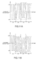
- Figs. 11A and 11B explain an example of control of a discharge lamp lighting apparatus according to an embodiment of the invention.
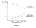
- Fig. 12 explains an example of control of a discharge lamp lighting apparatus according to an embodiment of the invention.
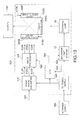
- Fig. 13 explains an exemplary configuration of a projector according to an embodiment of the invention.
- Fig. 1 is a descriptive diagram showing a projector 500 as an embodiment of the invention.
- the projector 500 includes a light source 200, a parallelizing lens 305, an illumination system 310, a color separation system 320, three liquid crystal light valves 330R, 330G, and 330 B, a cross dichroic prism 340, and a projection system 350.
- the light source 200 includes a light source unit 210 and a discharge lamp lighting apparatus 10.
- the light source unit 210 includes a primary reflection mirror 112 and a discharge lamp 90.
- the discharge lamp lighting apparatus 10 supplies power to the discharge lamp 90 to turn on the discharge lamp 90.
- the primary reflection mirror 112 reflects the light emitted from the discharge lamp 90 in the illumination direction D.
- the illumination direction D is parallel to an optical axis AX.
- the light from the light source unit 210 passes through the parallelizing lens 305 and enters the illumination system 310.
- the parallelizing lens 305 parallelizes the light from the light source unit 210.
- the illumination system 310 makes the illuminance of the light from the light source 200 uniform in the liquid crystal light valves 330R, 330G, and 330 B.
- the illumination system 310 aligns the polarization directions of the light beams from the light source 200 in order to effectively use the light from the light source 200 in the liquid crystal light valves 330R, 330G, and 330 B.
- the light adjusted in terms of the illuminance distribution and the polarization direction enters the color separation system 320.
- the color separation system 320 separates the incident light into three, red (R), green (G), and blue (B), color light beams.
- the three color light beams are modulated by the liquid crystal light valves 330R, 330G, and 330 B, which are related to the respective colors.
- the liquid crystal light valves 330R, 330G, and 330 B include liquid crystal panels 560R, 560G, and 560B and polarizers disposed on the light incident side and light exiting side of the liquid crystal panels 560R, 560G and 560B.
- the three modulated color light beams are combined in the cross dichroic prism 340.
- the combined light enters the projection system 350.
- the projection system 350 projects the incident light on a screen (not shown). An image is thus displayed on the screen.
- a variety of known configurations can be applied to the parallelizing lens 305, the illumination system 310, the color separation system 320, the cross dichroic prism 340, and the projection system 350.
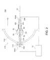
- Fig. 2 is a descriptive diagram showing the configuration of the light source 200.
- the light source 200 includes the light source unit 210 and the discharge lamp lighting apparatus 10.
- Fig. 2 shows a cross-sectional view ofthe light source unit 210.
- the light source unit 210 includes the primary reflection mirror 112, the discharge lamp 90, and a secondary mirror 50.
- the discharge lamp 90 has a rod shape extending from a first end 90e1 to a second end 90e2 along the illumination direction D.
- the discharge lamp 90 is made of quartz glass or any other suitable light-transmissive material.
- the central portion of the discharge lamp 90 is spherically convex, where a discharge space 91 is formed.
- the discharge space 91 encapsulates gas, which is a discharge medium containing a rare gas, a metallic halide compound, and other materials.
- Electrode tips (also called “discharge ends") of the electrodes 92 and 93 face each other in the discharge space 91 and are spaced apart by a predetermined distance.
- the electrodes 92 and 93 are made of tungsten or any other suitable metal.
- a first terminal 536 is provided at the first end 90e1 of the discharge lamp 90.
- the first terminal 536 is electrically connected to the first electrode 92 via a conductive member 534 that passes inside the discharge lamp 90.
- a second terminal 546 is provided at the second end 90e2 of the discharge lamp 90.
- the second terminal 546 is electrically connected to the second electrode 93 via a conductive member 544 that passes inside the discharge lamp 90.
- Each of the terminals 536 and 546 is made of tungsten or any other suitable metal.
- Each of the conductive members 534 and 544 is formed of, for example, a molybdenum foil.
- the terminals 536 and 546 are connected to the discharge lamp lighting apparatus 10.
- the discharge lamp lighting apparatus 10 supplies an AC current to the terminals 536 and 546.
- arc discharge occurs between the two electrodes 92 and 93.
- the light produced by the arc discharge (discharged light) is radiated from the discharge position in every direction, as indicated by the broken-line arrows.
- the primary reflection mirror 112 is fixed with a fixing member 114 to the first end 90e1 of the discharge lamp 90.
- the reflection surface of the primary reflection mirror 112 (the surface facing the discharge lamp 90) has a spheroidal shape.
- the primary reflection mirror 112 reflects the discharged light in the illumination direction D.
- the reflection surface of the primary reflection mirror 112 does not necessarily have a spheroidal shape but can have a variety of shapes that reflect the discharged light in the illumination direction D. For example, a paraboloidal shape may be used.
- the primary reflection mirror 112 can convert the discharged light into light substantially parallel to the optical axis AX.
- the parallelizing lens 305 can therefore be omitted.
- the secondary mirror 50 is fixed with a fixing member 522 on the second end 90e2 side of the discharge lamp 90.
- the reflection surface (the surface facing the discharge lamp 90) of the secondary mirror 50 has a spherical shape that surrounds the second end 90e2 side of the discharge space 91.
- the secondary mirror 50 reflects the discharged light toward the primary reflection mirror 112. The above configuration allows the light radiated from the discharge space 91 to be more efficiently used.
- the fixing members 114 and 522 can be made of an arbitrary heat-resistant material (an inorganic adhesive, for example) that withstands the heat produced in the discharge lamp 90.
- an arbitrary heat-resistant material an inorganic adhesive, for example
- the primary reflection mirror 112 and the secondary reflection mirror 50 are not necessarily fixed to the discharge lamp 90, but an arbitrary method can be employed.
- the discharge lamp 90 and the primary reflection mirror 112 may be independently fixed to an enclosure (not shown) of the projector. The same argument applies to the secondary mirror 50.
- Fig. 3 is an example of the circuit diagram of the discharge lamp lighting apparatus according to the present embodiment.
- the discharge lamp lighting apparatus 10 includes a power control circuit 20.
- the power control circuit 20 controls driving power supplied to the discharge lamp 90.
- the power control circuit 20 is comprised of a down chopper circuit that uses a DC power supply 80 as an input source, lowers the input voltage, and outputs a DC current Id.
- the power control circuit 20 may include a switching device 21, a diode 22, a coil 23, and a capacitor 24.
- the switching device 21 may be comprised of a transistor or any other suitable component.
- one end of the switching device 21 is connected to the positive voltage side of the DC power supply 80, and the other end is connected to the cathode terminal of the diode 22 and one end of the coil 23.
- the other end of the coil 23 is connected to one end of the capacitor 24, and the other end of the capacitor 24 is connected to the anode terminal of the diode 22 and the negative voltage side of the DC power supply 80.
- a current control signal is inputted from a controller 40 to a control terminal of the switching device 21 to control ON and OFF of the switching device 21.
- the current control signal may be a PWM control signal or any other suitable signal.
- the discharge lamp lighting apparatus 10 further includes an AC conversion circuit 30.
- the AC conversion circuit 30 receives as an input the DC current Id outputted from the power control circuit 20, and reverses the polarity of the DC current Id at predetermined timings to produce and output a discharge lamp driving current having an arbitrary frequency and duty ratio.
- the duty ratio is defined as the proportion of the period of the first polarity to one cycle of the discharge lamp driving AC current I.
- the AC conversion circuit 30 is comprised of an inverter bridge circuit (full-bridge circuit).
- the AC conversion circuit 30 includes, for example, first to fourth switching devices 31 to 34, such as transistors, and the first and second switching devices 31, 32 connected in series are connected in parallel to the third and fourth switching devices 33, 34 connected in series.
- Frequency control signals are inputted from the controller 40 to control terminals of the first to fourth switching devices 31 to 34 to control ON and OFF of the first to fourth switching devices 31 to 34.
- the AC conversion circuit 30 alternately reverses the polarity of the DC current Id outputted from the power control circuit 20 by repeatedly turning the first and fourth switching devices 31, 34 and the second and third switching devices 32, 33 alternately on and off so as to produce the discharge lamp driving AC current I having a controlled frequency and duty ratio and output it from a common connection point between the first and second switching devices 31, 32 and a common connection point between the third and fourth switch devices 33, 34.
- the second and third switching devices 32, 33 are controlled to be OFF, whereas when the first and fourth switching devices 31, 34 are OFF, the second and third switching devices 32, 33 are controlled to be ON. Therefore, when the first and fourth switching devices 31, 34 are ON, the produced discharge lamp driving AC current I flows from one end of the capacitor 24 through the first switching device 31, the discharge lamp 90, and the fourth switching device 34 in this order. On the other hand, when the second and third switching devices 32, 33 are ON, the produced discharge lamp driving AC current I flows from one end of the capacitor 24 through the third switching device 33, the discharge lamp 90, and the second switching device 32 in this order.
- the discharge lamp lighting apparatus 10 further includes the controller 40.
- the controller 40 controls the power control circuit 20 and the AC conversion circuit 30 to control the magnitude, frequency, duty ratio, and waveform of the discharge lamp driving AC current I.
- the control circuit 40 controls the AC conversion circuit 30 to perform AC conversion control, and controls the power control circuit 20 to perform section current control. In the AC conversion control, the timings at which the polarity of the discharge lamp driving AC current I is reversed are used to control the frequency and the duty ratio. In the section current control, the magnitude of the outputted DC current Id is controlled.
- the controller 40 externally receives a power control signal S and sets the average of the DC current Id outputted from the power control circuit 20 to the current magnitude that corresponds to the power control signal S.
- the power control signal S may be a signal whose value continuously changes, such as a signal based on user's dimming operation, or a signal whose value discretely changes, such as a signal based on user's mode switching operation (for example, switching between a high-luminance mode driven at a high power level and a long-life mode driven at a low power level).
- the configuration of the controller 40 is not limited to a specific one.
- the controller 40 in the present embodiment includes a system controller 41, a power control circuit controller 42, and an AC conversion circuit controller 43. Part or all of the controller 40 may be comprised of a semiconductor integrated circuit.
- the system controller 41 controls the power control circuit controller 42 and the AC conversion circuit controller 43 to control the power control circuit 20 and the AC conversion circuit 30.
- the system controller 41 may control the power control circuit controller 42 and the AC conversion circuit controller 43 based on the discharge lamp driving voltage and the discharge lamp driving AC current I detected by an operation detector 60, which will be described later, provided in the discharge lamp lighting apparatus 10.
- the system controller 41 further includes a storage unit 44.
- the storage unit 44 may be provided independently of the system controller 41.
- the system controller 41 may control the power control circuit 20 and the AC conversion circuit 30 based on information stored in the storage unit 44.
- the storage unit 44 may store, for example, information on the magnitude, frequency, duty ratio, and waveform of the discharge lamp driving AC current I.
- the power control circuit controller 42 outputs the current control signal to the power control circuit 20 based on a control signal from the system controller 41 so as to control the power control circuit 20.
- the AC conversion circuit controller 43 outputs a reverse control signal to the AC conversion circuit 30 based on a control signal from the system controller 41 so as to control the AC conversion circuit 30.
- the discharge lamp lighting apparatus 10 may include the operation detector 60.
- the operation detector 60 may detect the operation of the discharge lamp 90, for example, the discharge lamp driving voltage and the discharge lamp driving AC current I, and output driving voltage information and driving current information.
- the operation detector 60 includes first to third resistors 61 to 63.
- the operation detector 60 detects the discharge lamp driving voltage using the voltages divided by the first and second resistors 61, 62 connected in parallel to the discharge lamp 90 and connected in series to each other, and detects the discharge lamp driving AC current I using the voltage produced in the third resistor 63 connected in series to the discharge lamp 90.
- the discharge lamp lighting apparatus 10 may include an igniter circuit 70.
- the igniter circuit 70 operates only when the discharge lamp 90 is turned on, and supplies a high voltage (a voltage higher than that in a typical control operation) between the electrodes of the discharge lamp 90, the high voltage required to cause dielectric breakdown between the electrodes of the discharge lamp 90 to form a discharge path when the discharge lamp 90 is turned on.
- the igniter circuit 70 is connected in parallel to the discharge lamp 90.
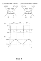
- Figs. 4A to 4D are descriptive diagrams showing the relationship between the polarity of the driving power supplied to the discharge lamp 90 and the temperature of the electrodes.
- Figs. 4A and 4B show how the two electrodes 92 and 93 operate.
- Figs. 4A and 4B show the tips of the two electrodes 92 and 93.
- Protrusions 552P and 562P are provided at the tips of the electrodes 92 and 93, respectively. Discharge occurs between the protrusions 552P and 562P.
- the shift of the discharge position (arc position) in each of the electrodes 92 and 93 can be suppressed as compared to a case where no protrusions are provided. It is noted, however, that such protrusions may be omitted.
- Fig. 4A shows a first polarity state P1 in which the first electrode 92 acts as the anode and the second electrode 93 acts as the cathode.
- discharge causes electrons to move from the second electrode 93 (cathode) to the first electrode 92 (anode).
- the cathode (second electrode 93) discharges electrons.
- the electrons discharged from the cathode (second electrode 93) impinge on the tip of the anode (first electrode 92). The impingement produces heat, which increases the temperature at the tip (protrusion 552P) of the anode (first electrode 92).
- Fig. 4B shows a second polarity state P2 in which the first electrode 92 acts as the cathode and the second electrode 93 acts as the anode.
- the second polarity state P2 electrons move from the first electrode 92 to the second electrode 93 in contrast to the first polarity state P1.
- the temperature at the tip (protrusion 562P) of the second electrode 93 increases.
- the temperature of the anode readily becomes higher than that of the cathode.
- the temperature of one of the electrodes continues to be higher than that of the other electrode, a variety of problems may occur.
- the tip of the hot-side electrode melts excessively, the electrode may suffer from an unexpected deformation.
- the arc length may deviate from an adequate value.
- tiny irregularities produced at the tip may not melt but remain.
- what is called an arc jump may occur (the arc position is not stable but moved).
- Fig. 4C is a timing chart showing AC power (drive signal) supplied to the discharge lamp 90 ( Fig. 2 ).
- the horizontal axis represents the time T, and the vertical axis represents the current I.
- the current I represents the current flowing through the discharge lamp 90.
- Positive values represent the first polarity state P1
- negative values represent the second polarity state P2.
- a rectangular-wave AC current is used, and the first polarity state P1 and the second polarity state P2 are alternately repeated.
- a first polarity section Tp represents a period during which the first polarity state P1 continues
- a second polarity section Tn is a period during which the second polarity state P2 continues.
- the average current magnitude in the first polarity section Tp is +A0 (Im1)
- the average current magnitude in the second polarity section Tn is -A0 (-Im2).
- the drive frequency can be experimentally determined in accordance with the characteristics of the discharge lamp 90 (a value within a range from 30 Hz to 1 KHz is used, for example).
- the other values +A0, -A0, Tp, and Tn can be experimentally determined as well.
- Fig. 4D is a timing chart showing the change in the temperature of the first electrode 92.
- the horizontal axis represents the time T, and the vertical axis represents the temperature H.
- the temperature H of the first electrode 92 increases, whereas in the second polarity state P2, the temperature H of the first electrode 92 decreases. Since the first polarity state P1 and the second polarity state P2 are alternately repeated, the temperature H periodically changes between a minimum value Hmin and a maximum value Hmax.
- the temperature of the second electrode 93 changes in opposite phase to the temperature H of the first electrode 92. That is, the temperature of the second electrode 93 decreases in the first polarity state P1, whereas the temperature of the second electrode 93 increases in the second polarity state P2.
- the tip of the first electrode 92 melts, the tip ofthe first electrode 92 (protrusion 552P) becomes smooth. The discharge position in the first electrode 92 will not therefore be shifted.
- the temperature at the tip of the second electrode 93 decreases, the second electrode 93 (protrusion 562P) will not melt excessively. No unexpected electrode deformation will therefore occur.
- the behaviors of the first electrode 92 and the second electrode 93 are reversed. The problems with the two electrodes 92 and 93 can therefore be eliminated by repeating the two states P1 and P2.
- the controller 40 in the discharge lamp lighting apparatus 10 performs control in which accumulated energy supplied to the electrodes 92 and 93 of the discharge lamp in one cycle of the discharge lamp driving AC current I is changed in accordance with a periodic pattern.
- the periodic pattern includes a plurality of segmented periods during each of which the accumulated energy supplied to the electrodes 92 and 93 of the discharge lamp is maintained at the same level for a plurality of cycles of the discharge lamp driving AC current I, and the accumulated energy levels supplied to the electrodes 92 and 93 of the discharge lamp in at least two of the segmented periods differ from each other.
- the controller 40 performs current control in which the controller 40 externally receives a power control signal S and sets the average of the DC current Id outputted from the power control circuit 20 in the section that corresponds to one cycle of the discharge lamp driving AC current I to the current magnitude that corresponds to the power control signal S.
- the controller 40 controls the magnitude of the accumulated energy supplied to the electrodes 92 and 93 of the discharge lamp in relation to the average of the DC current Id.
- the controller 40 may increase the difference between the maximum value and the minimum value of the accumulated energy supplied to the electrodes 92 and 93 of the discharge lamp as the average of the DC current Id decreases.
- the accumulated energy is the energy that corresponds to the amount of power supplied from the discharge lamp lighting apparatus in the period during which either of the electrodes 92 and 93 acts as the anode.
- the accumulated energy supplied to the electrodes 92 and 93 of the discharge lamp 90 in one cycle of the discharge lamp driving AC current I is changed in accordance with a periodic pattern including a plurality of segmented periods during each of which the accumulated energy supplied to the electrodes 92 and 93 of the discharge lamp 90 in one cycle of the discharge lamp driving AC current I is maintained at the same level for a plurality of cycles of the discharge lamp driving AC current I.
- the accumulated energy supplied to the electrodes of the discharge lamp 90 in one cycle of the AC current I is changed in the periodic pattern including a plurality of segmented periods, whereas the accumulated energy supplied to the electrodes of the discharge lamp 90 in one cycle of the AC current I can be temporarily fixed in at least one of the segmented periods.
- the thermal condition in the electrodes 92 and 93 and in the vicinity thereof can be greatly changed in a relatively long time scale. It is therefore possible to suppress the formation of steady convection in the discharge lamp 90 so as to prevent uneven consumption of the electrodes 92 and 93 and uneven precipitation of the electrode material.
- the temperature of the electrode that receives lower accumulated energy supplied in one cycle is lower than that of the other.
- the power (energy) supplied to the electrodes 92 and 93 is low, and hence the electrode temperature is low.
- the power for driving the discharge lamp 90 is proportional to the DC current Id.
- controlling the magnitude of the accumulated energy supplied to the electrodes 92 and 93 of the discharge lamp in relation to the average of the DC current Id, that is, the power for driving the discharge lamp 90 allows the electrode temperature to vary in the largest possible range even when the discharge lamp is driven at a low power level. It is therefore possible to suppress the formation of steady convection in the discharge lamp 90 so as to prevent uneven consumption of the electrodes 92 and 93 and uneven precipitation of the electrode material. For example, increasing the difference between the maximum value and the minimum value of the accumulated energy supplied to the electrodes 92 and 93 of the discharge lamp allows the electrode temperature to vary in the largest possible range even when the discharge lamp is driven at a low power level.
- the accumulated energy supplied to the electrodes 92 and 93 may be controlled by using the duty ratio of the discharge lamp driving AC current I or may be controlled by using the magnitude of the discharge lamp driving AC current I.
- the duty ratio of the discharge lamp driving AC current I is the proportion of the first polarity section Tp to one cycle of the AC current I.
- the controller 40 performs AC conversion control in which the duty ratio of the discharge lamp driving AC current I is changed in accordance with a periodic pattern.
- the periodic pattern includes a plurality of segmented periods during each of which the duty ratio of the discharge lamp driving AC current I is maintained at the same value for a plurality of cycles of the discharge lamp driving AC current I, and the duty ratios of the discharge lamp driving AC current I in at least two of the segmented periods differ from each other.
- a first polarity of the discharge lamp driving AC current I be a case where the first electrode 92 of the discharge lamp 90 is the anode
- a second polarity be a case where the first electrode 92 is the cathode.
- the duty ratio is the proportion of the period of the first polarity to one cycle of the discharge lamp driving AC current whose polarity is switched between the first polarity and the second polarity.
- the controller 40 performs current control in which the controller 40 externally receives a power control signal S and sets the average of the DC current Id outputted from the power control circuit 20 in the section that corresponds to one cycle of the discharge lamp driving AC current to the current magnitude that corresponds to the power control signal S. At the same time, the controller 40 performs AC conversion control in which the difference between at least one of the maximum and minimum values of the duty ratio of the discharge lamp driving AC current I and a reference duty ratio is controlled in relation to the average of the DC current Id outputted from the power control circuit 20.
- the controller 40 may perform the AC conversion control as follows: The difference between at least one of the maximum and minimum values of the duty ratio of the discharge lamp driving AC current I and a reference duty ratio is increased as the average of the DC current Id, that is, the power for driving the discharge lamp 90 decreases.
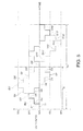
- Fig. 5 shows an example of the periodic pattern in accordance with which the duty ratio of the discharge lamp driving AC current I is changed.
- the horizontal axis represents time, and the vertical axis represents the duty ratio.
- the solid line represents a first periodic pattern in a case where the power for driving the discharge lamp 90 is 200 W, and the broken line represents a second periodic pattern in a case where the power for driving the discharge lamp 90 is 160 W.
- the reference duty ratio is 50%.
- the driving power of 200W is the effective average power per cycle of the first periodic pattern
- the driving power of 160W is the effective average power per cycle of the second periodic pattern.
- the controller 40 When the power for driving the discharge lamp 90 is 200W, the controller 40 performs AC conversion control in which one cycle Ta of the first periodic pattern includes 8 segmented periods (segmented periods D1 to D8) during each of which the duty ratio of the discharge lamp driving AC current I is maintained at the same value and between which the duty ratio is changed stepwise. That is, any of the segmented periods is a period during which the same AC conversion control continues in terms of one cycle unit of the discharge lamp driving AC current I. In the present embodiment, the length of one segmented period in the first periodic pattern is 8 seconds.
- the controller 40 performs AC conversion control in which one cycle Tb of the second periodic pattern includes 16 segmented periods (segmented periods D1' to D16') during each of which the duty ratio of the discharge lamp driving AC current I is maintained at the same value and between which the duty ratio is changed stepwise.
- the length of one segmented period in the second periodic pattern is 8 seconds, as in the case where the power for driving the discharge lamp 90 is 200W
- the duty ratio is 50% in the segmented period D1, and then the duty ratio is incremented in 5% steps to 60%, which is the maximum, in the segmented period D3. The duty ratio is then decremented in 5% steps to 40%, which is the minimum, in the sectioned period D7. The duty ratio is again incremented in 5% steps. The duty ratio is thus repeatedly incremented and decremented in the cycle of Ta.
- the duty ratio is 50% in the segmented period D1', and then the duty ratio is incremented in 5% steps to 70%, which is the maximum, in the sectioned period D5'. The duty ratio is then decremented in 5% steps to 30%, which is the minimum, in the sectioned period D13'. The duty ratio is again incremented in 5% steps. The duty ratio is thus repeatedly incremented and decremented in the cycle of Tb.
- both the maximum value (60%) and minimum value (40%) of the duty ratio of the discharge lamp driving AC current I differ from the reference duty ratio (50%) by 10%.
- both the maximum value (70%) and minimum value (30%) of the duty ratio of the discharge lamp driving AC current I differ from the reference duty ratio (50%) by 20%.
- Figs. 6A and 6B show the transition of the waveform of the discharge lamp driving AC current I when the duty ratio is changed in accordance with one of the periodic patterns shown in Fig. 5 .
- the horizontal axis represents time, and the vertical axis represents the current magnitude.
- the current control is performed in such a way that the average current magnitude for the first polarity is +A0 and the average current magnitude for the second polarity is -A0. While the following description will be made of the transition of the waveform when the power for driving the discharge lamp 90 is 200 W, the transition of the waveform when the power for driving the discharge lamp 90 is 160 W will be the same except the number of segmented periods and the maximum and minimum values of the duty ratio.
- Fig. 6A shows the transition of the waveform of the AC current I from the segmented period D1 to the segmented period D4 in Fig. 5 .
- the current waveform whose duty ratio is 50% continues.
- the current waveform is changed to the one whose duty ratio is 55%, which continues for the segmented period D2.
- the current waveform is changed to the one whose duty ratio is 60%, which continues for the segmented period D3.
- the current waveform is changed to the one whose duty ratio is 55%, which continues for the segmented period D4.
- Fig. 6B shows the transition of the waveform of the AC current I from the segmented period D5 to the segmented period D8 in Fig. 5 .
- the current waveform whose duty ratio is 50% continues.
- the current waveform is changed to the one whose duty ratio is 45%, which continues for the segmented period D6.
- the current waveform is changed to the one whose duty ratio is 40%, which continues for the segmented period D7.
- the current waveform is changed to the one whose duty ratio is 45%, which continues for the segmented period D8.
- the electrode temperature is desirable to change the electrode temperature within the largest possible range.
- the power (energy) supplied to the electrodes 92 and 93 is low, and hence the electrode temperature varies within a small range.
- the power for driving the discharge lamp 90 is proportional to the DC current Id.
- controlling the difference between at least one of the maximum and minimum values of the duty ratio of the discharge lamp driving AC current I and the reference duty ratio in relation to the average of the DC current Id, that is, the power for driving the discharge lamp 90 allows the electrode temperature to vary in the largest possible range even when the discharge lamp is driven at a low power level.
- the power for driving the discharge lamp 90 may be changed continuously or stepwise at a finer rate based on the power control signal S.
- the relationship between the range of the power for driving the discharge lamp 90 and the range of the duty ratio may be determined in advance, and the relationship data may be stored, for example, in the storage unit 44 in the controller 40.
- the temperature of one of the electrodes less likely decreases than the temperature of the other.
- An example of such a structure is that shown in Fig. 2 , where the secondary reflective mirror 50 covers the portion of the discharge lamp 90 that is on the second electrode 93 side.
- only one of the maximum and minimum values of the duty ratio of the discharge lamp driving AC current I may differ from the reference duty ratio, or one may differ by a greater amount than the other so that the maximum value of the proportion of the period during which the first electrode 92 acts as the anode to one cycle of the AC current I is greater than the maximum value of the proportion of the period during which the second electrode 93 acts as the anode to one cycle of the AC current I.
- the AC conversion control may be performed as follows: When the driving power is 200 W, the maximum value of the duty ratio is 60% (the difference from the reference duty ratio is 10%) and the minimum value of the duty ratio is 40% (the difference from the reference duty ratio is 10%), whereas when the driving power is 160 W, the maximum value of the duty ratio is 60% (the difference from the reference duty ratio is 10%) and the minimum value of the duty ratio is 30% (the difference from the reference duty ratio is 20%).
- the controller 40 may perform the AC conversion control as follows: The frequency of the discharge lamp driving AC current I is controlled in relation to the average of the DC current Id outputted from the power control circuit 20.
- the controller 40 may perform the AC conversion control as follows: The frequency of the discharge lamp driving AC current I is increased as the average of the DC current Id outputted from the power control circuit 20 decreases.
- the relationship between the power for driving the discharge lamp 90 and the frequency of the discharge lamp driving AC current I may be determined in advance, and the relationship data may be stored, for example, in the storage unit 44 in the controller 40.
- the control of increasing the difference between at least one of the maximum and minimum values of the duty ratio of the discharge lamp driving AC current I and the reference duty ratio when the discharge lamp 90 is driven at a low power level as compared with the case where the discharge lamp 90 is driven at a high power level in combination with the control of increasing the frequency of the discharge lamp driving AC current I as the magnitude of the DC current Id outputted from the power control circuit 20 decreases, can not only suppress the formation of steady convection in the discharge lamp 90 to prevent uneven consumption of the electrodes and uneven precipitation of the electrode material, but also prevent flickering.
- the controller 40 performs section current control in which the difference in the absolute value of the current magnitude between the first polarity section and the second polarity section of the discharge lamp driving AC current I is changed in accordance with a periodic pattern.
- the periodic pattern includes a plurality of segmented periods during each of which the difference in the absolute value of the current magnitude between the first polarity section and the second polarity section is maintained at the same value for a plurality of cycles of the discharge lamp driving AC current I, and the differences in the absolute value of the current magnitude between the first polarity section and the second polarity section in at least two of the segmented periods differ from each other.
- the controller 40 performs section current control in which the controller 40 externally receives a power control signal S and sets the average of the DC current Id outputted from the power control circuit 20 in the section that corresponds to one cycle of the discharge lamp driving AC current to the current magnitude that corresponds to the power control signal S, and the difference in the absolute value of the current magnitude between the first polarity section and the second polarity section is controlled in relation to the average of the DC current Id outputted from the power control circuit 20.
- the controller 40 may perform the section current control as follows: At least one of the absolute values of the maximum and minimum values of the difference in the absolute value of the current magnitude between the first polarity section and the second polarity section is increased as the average of the DC current Id, that is, the power for driving the discharge lamp 90 decreases.
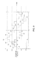
- Fig. 9 shows an example of the periodic pattern in accordance with which the difference in the absolute value of the current magnitude between the first polarity section and the second polarity section of the discharge lamp driving AC current I is changed.
- the horizontal axis represents time
- the vertical axis represents the difference in the absolute value of the current magnitude between the first polarity section and the second polarity section of the discharge lamp driving AC current I.
- the solid line represents a first periodic pattern in a case where the power for driving the discharge lamp 90 is 200 W
- the broken line represents a second periodic pattern in a case where the power for driving the discharge lamp 90 is 160 W.
- the controller 40 When the power for driving the discharge lamp 90 is 200W, the controller 40 performs section current control in which one cycle Ta of the first periodic pattern includes 8 segmented periods (segmented periods D1 to D8) during each of which the difference in the absolute value of the current magnitude between the first polarity section and the second polarity section of the discharge lamp driving AC current I is maintained at the same value, and the difference in the absolute value of the current magnitude between the first polarity section and the second polarity section of the discharge lamp driving AC current I is changed stepwise. That is, any of the segmented periods is a period during which the same section current control continues in terms of one cycle unit of the discharge lamp driving AC current I. In the present embodiment, the length of one segmented period of the first periodic pattern is 8 seconds.
- the controller 40 performs section current control in which one cycle Tb of the second periodic pattern includes 16 segmented periods (segmented periods D1' to D16') during each of which the difference in the absolute value of the current magnitude between the first polarity section and the second polarity section of the discharge lamp driving AC current I is maintained at the same value, and the difference in the absolute value of the current magnitude between the first polarity section and the second polarity section of the discharge lamp driving AC current I is changed stepwise.
- the length of one segmented period of the second periodic pattern is 8 seconds, as in the case where the power for driving the discharge lamp 90 is 200W.
- the difference in the absolute value of the current magnitude between the first polarity section and the second polarity section of the discharge lamp driving AC current I is then decremented in 0.1 A steps to -0.2 A, which is the minimum, in the segmented period D7.
- the difference in the absolute value of the current magnitude between the first polarity section and the second polarity section of the discharge lamp driving AC current I is again incremented in 0.1 A steps.
- the difference in the absolute value of the current magnitude between the first polarity section and the second polarity section of the discharge lamp driving AC current I is thus repeatedly incremented and decremented in the cycle of Ta.
- the difference in the absolute value of the current magnitude between the first polarity section and the second polarity section of the discharge lamp driving AC current I is 0 A in the segmented period D1', and then the difference in the absolute value of the current magnitude between the first polarity section and the second polarity section of the discharge lamp driving AC current I is incremented in 0.1 A steps to +0.4 A, which is the maximum, in the segmented period D5'.
- the difference in the absolute value of the current magnitude between the first polarity section and the second polarity section of the discharge lamp driving AC current I is then decremented in 0.1 A steps to -0.4 A, which is the minimum, in the segmented period D13'.
- the difference in the absolute value of the current magnitude between the first polarity section and the second polarity section of the discharge lamp driving AC current I is again incremented in 0.1 A steps.
- the difference in the absolute value of the current magnitude between the first polarity section and the second polarity section of the discharge lamp driving AC current I is thus repeatedly incremented and decremented in the cycle of Tb.
- both the absolute values of the maximum and minimum values of the difference in the absolute value of the current magnitude between the first polarity section and the second polarity section are 0.2 A.
- both the absolute values of the maximum and minimum values of the difference in the absolute value of the current magnitude between the first polarity section and the second polarity section are 0.4 A.
- Fig. 10A shows the waveform of the DC current Id outputted from the power control circuit 20 and the waveform of the discharge lamp driving AC current I when the difference in the absolute value of the current magnitude between the first polarity section Tp and the second polarity section Tn of the discharge lamp driving AC current I is 0 A.
- the horizontal axis represents time, and the vertical axis represents the current magnitude.
- the time stamps t1, t2, and t3 represent the timings where the polarity of the discharge lamp driving AC current I is reversed.
- the AC current I has the first polarity (the first electrode 92 acts as the anode), and the section is called the first polarity section (section Tp).
- the AC current I has the second polarity (the first electrode 92 acts as the cathode), and the section is called the second polarity section (section Tn).
- the section Tp and the section Tn combines to form one cycle of the AC current I.
- the duty ratio of the discharge lamp driving AC current I is defined as the proportion of the first polarity section Tp to one cycle of the AC current I. In the examples shown in Figs. 10A to 10E , the duty ratio is 50%.
- the section current control is performed as follows: the DC current Id outputted from the power control circuit 20 is set to the same current magnitude (+A0) in the sections Tp and Tn.
- the discharge lamp driving AC current I has a current magnitude of (+A0) in the section Tp and a current magnitude of (-A0) in the section Tn. That is, the difference in the absolute value of the current magnitude between the first polarity section and the second polarity section of the discharge lamp driving AC current I is 0 A.
- the section current control is performed as follows: The magnitude of the DC current Id outputted from the power control circuit 20 is set to +A0+0.05 A in the section Tp, and the magnitude of the DC current Id outputted from the power control circuit 20 is set to +A0-0.05 A in the section Tn.
- the discharge lamp driving AC current I has a current magnitude of (+A0+0.05 A) in the section Tp and a current magnitude of (-A0+0.05 A) in the section Tn.
- the difference in the absolute value of the current magnitude between the first polarity section and the second polarity section of the discharge lamp driving AC current I is +0.1 A.
- the difference in the absolute value of the current magnitude between the first polarity section and the second polarity section of the discharge lamp driving AC current I is +0.2 A.
- the difference in the absolute value of the current magnitude between the first polarity section and the second polarity section of the discharge lamp driving AC current I is -0.1 A.
- the difference in the absolute value of the current magnitude between the first polarity section and the second polarity section of the discharge lamp driving AC current I is -0.2 A.
- Figs. 11A and 11B show the transition of the waveform of the discharge lamp driving AC current I when the difference in the absolute value of the current magnitude between the first polarity section and the second polarity section of the discharge lamp driving AC current I is changed in accordance with the periodic pattern shown in Fig. 9 .
- the horizontal axis represents time, and the vertical axis represents the current magnitude. While the following description will be made of the transition of the waveform when the power for driving the discharge lamp 90 is 200 W, the transition of the waveform when the power for driving the discharge lamp 90 is 160 W will be the same except the number of segmented periods and the maximum and minimum values of the difference in the absolute value of the current magnitude between the first polarity section and the second polarity section of the discharge lamp driving AC current I.
- Fig. 11A shows the transition of the waveform of the AC current I from the segmented period D1 to the segmented period D4 in Fig. 9 .
- the current waveform with a difference in the absolute value of the current magnitude of 0 A between the first polarity section and the second polarity section of the discharge lamp driving AC current I continues.
- the current waveform is changed to the one with a difference in the absolute value of the current magnitude of +0.1 A between the first polarity section and the second polarity section of the discharge lamp driving AC current I, and the new current waveform continues for the segmented period D2.
- the current waveform is changed to the one with a difference in the absolute value of the current magnitude of +0.2 A between the first polarity section and the second polarity section of the discharge lamp driving AC current I, and the new current waveform continues for the segmented period D3.
- the current waveform is changed to the one with a difference in the absolute value of the current magnitude of +0.1 A between the first polarity section and the second polarity section of the discharge lamp driving AC current I, and the new current waveform continues for the segmented period D4.
- Fig. 11B shows the transition of the waveform of the AC current I from the segmented period D5 to the segmented period D8 in Fig. 9 .
- the current waveform with a difference in the absolute value of the current magnitude of 0 A between the first polarity section and the second polarity section of the discharge lamp driving AC current I continues.
- the current waveform is changed to the one with a difference in the absolute value of the current magnitude of -0.1 A between the first polarity section and the second polarity section of the discharge lamp driving AC current I, and the new current waveform continues for the segmented period D6.
- the current waveform is changed to the one with a difference in the absolute value of the current magnitude of -0.2 A between the first polarity section and the second polarity section of the discharge lamp driving AC current I, and the new current waveform continues for the segmented period D7.
- the current waveform is changed to the one with a difference in the absolute value of the current magnitude of -0.1 A between the first polarity section and the second polarity section of the discharge lamp driving AC current I, and the new current waveform continues for the segmented period D8.
- the electrode temperature is desirable to change the electrode temperature within the largest possible range.
- the power (energy) supplied to the electrodes 92 and 93 is low, and hence the electrode temperature varies within a small range.
- the power for driving the discharge lamp 90 is proportional to the DC current Id.
- controlling the difference in the absolute value of the current magnitude between the first polarity section and the second polarity section of the discharge lamp driving AC current I in relation to the average of the DC current Id, that is, the power for driving the discharge lamp 90 allows the electrode temperature to vary in the largest possible range even when the discharge lamp is driven at a low power level.
- the power for driving the discharge lamp 90 may be changed continuously or stepwise at a finer rate based on the power control signal S.
- the relationship between the power for driving the discharge lamp 90 and the maximum and minimum values of the difference in the absolute value of the current magnitude between the first polarity section and the second polarity section of the discharge lamp driving AC current I may be determined in advance, and the relationship data may be stored, for example, in the storage unit 44 in the controller 40.
- the temperature of one of the electrodes less likely decreases than the temperature of the other.
- An example of such a structure is that shown in Fig. 2 , where the secondary reflective mirror 50 covers the portion of the discharge lamp 90 that is on the second electrode 93 side.
- the absolute value of only one of the maximum and minimum values of the difference in the absolute value of the current magnitude between the first polarity section and the second polarity section of the discharge lamp driving AC current I is greater than zero, or one is greater than the other so that the maximum value of the proportion of the period during which the first electrode 92 acts as the anode to one cycle of the AC current I is greater than the maximum value of the proportion of the period during which the second electrode 93 acts as the anode to one cycle of the AC current I.
- the section current control may be performed as follows: When the driving power is 200 W, the maximum value of the difference in the absolute value is +0.2 A and the minimum value of the difference in the absolute value is -0.2 A, whereas when the driving power is 160 W, the maximum value of the difference in the absolute value is +0.2 A and the minimum value of the difference in the absolute value is -0.4 A.
- the controller 40 may perform the AC conversion control as follows: The frequency of the discharge lamp driving AC current I is controlled in relation to the average of the DC current Id outputted from the power control circuit 20.
- the controller 40 may perform the AC conversion control as follows: The frequency of the discharge lamp driving AC current I is increased as the average of the DC current Id outputted from the power control circuit 20 decreases.
- the relationship between the power for driving the discharge lamp 90 and the frequency of the discharge lamp driving AC current I may be determined in advance, and the relationship data may be stored, for example, in the storage unit 44 in the controller 40.
- the control of increasing at least one of the absolute values of the maximum and minimum values of the difference in the absolute value of the current magnitude between the first polarity section and the second polarity section of the discharge lamp driving AC current I when the discharge lamp 90 is driven at a lower power level as compared with the case where the discharge lamp 90 is driven at a high power level in combination with the control of increasing the frequency of the discharge lamp driving AC current I as the magnitude of the DC current Id outputted from the power control circuit 20 decreases, can not only suppress the formation of steady convection in the discharge lamp 90 to prevent uneven consumption of the electrodes and uneven precipitation of the electrode material, but also prevent flickering.
- a combination of the control described with reference to Figs. 5-8 and the control described with reference to Figs. 8-12 is also contemplated.
- Fig. 13 shows an example of the circuit configuration of the projector according to the present embodiment.
- the projector 500 includes not only the optical system described above, but also an image signal converter 510, a DC power supply 520, the discharge lamp lighting apparatus 10, a discharge lamp 90, the liquid crystal panels 560R, 560G, and 560B, and an image processor 570.
- the image signal converter 510 converts an externally inputted image signal 502 (such as a luminance-chrominance signal and an analog RGB signal) into a digital RGB signal with a predetermined word length to produce image signals 512R, 512G, and 512B and supplies them to the image processor 570.
- an externally inputted image signal 502 such as a luminance-chrominance signal and an analog RGB signal
- a digital RGB signal with a predetermined word length to produce image signals 512R, 512G, and 512B and supplies them to the image processor 570.
- the image processor 570 performs image processing on the three image signals 512R, 512G, and 512B and outputs drive signals 572R, 572G, and 572B for driving the liquid crystal panels 560R, 560G, and 560B.
- the DC power supply 520 converts an AC voltage supplied from an external AC power supply 600 into a constant DC voltage and supplies the DC voltage to the image signal converter 510 and the image processor 570 on the secondary side of a transformer (although not illustrated but included in the DC power supply 520), and to the discharge lamp lighting apparatus 10 on the primary side of the transformer.
- the discharge lamp lighting apparatus 10 produces a high voltage between the electrodes ofthe discharge lamp 90 when the discharge lamp 90 is turned on to cause dielectric breakdown so as to form a discharge path, and then supplies a driving current for allowing the discharge lamp 90 to maintain the discharge.
- the liquid crystal panels 560R, 560G, and 560B use the drive signals 572R, 572G, and 572B according to the image signals to modulate the luminance values of the color light beams of the resultant images incident on the respective liquid crystal panels.
- a CPU 580 controls all operations of the projector including starting and terminating the projector.
- the CPU 580 When the projector is turned on and the output voltage from the DC power supply 520 becomes a predetermined value, the CPU 580 generates a start signal 582 and supplies it to the discharge lamp lighting apparatus 10.
- the CPU 580 may additionally supply a power control signal 584 to the discharge lamp lighting apparatus 10. Further, the CPU 580 may receive information 532 on the start status of the discharge lamp 90 from the discharge lamp lighting apparatus 10.
- the projector 500 can suppress the formation of steady convection in the discharge lamp to prevent uneven consumption of the electrodes and uneven precipitation of the electrode material even when the discharge lamp is driven at a low power level, the projector can maintain its projection luminance for a long period.
- the invention is also applicable to a projector using one liquid crystal panel, a projector using two liquid crystal panels, and a projector using four or more liquid crystal panels.
- transmission-type used herein means that an electro-optic modulator as a light modulator is of light-transmitting type, such as a transmissive liquid crystal panel
- reflection-type used herein means that the electro-optic modulator as the light modulator is of light-reflecting type, such as a reflective liquid crystal panel and a micromirror light modulator.
- a DMD Digital Micromirror Device: a trademark of Texas Instruments
- the invention is applied to a reflection-type projector, the same advantageous effects as those provided in a transmission-type projector can also be provided.
- the invention is applicable not only to a front projection projector that projects a projection image from the observation side but also to a rear projection projector that projects a projection image from the side opposite the observation side.
- the invention encompasses any configuration that is effectively the same as the configuration described with reference to the above embodiments (for example, a configuration having the same function, using the same method, and providing the same result, or a configuration having the same object and providing the same result).
- the invention also encompasses a configuration that is similar to the configuration described with reference to the above embodiments but has a non-essential portion replaced.
- the invention also encompasses a configuration providing the same advantageous effect as that provided in the configuration described with reference to the above embodiments or a configuration capable achieving the same object as that of the configuration described with reference to the above embodiments.
- the invention also encompasses a configuration that is similar to the configuration described with reference to the above embodiments but to which a known technology is added.
- the controller 40 may perform section current control in which the magnitude of the DC current Id is maximized in the second half of each of the first and second polarity sections.
- controller 40 may perform section current control in which the magnitude of the DC current Id is monotonously increased in each of the first and second polarity sections. Further, the controller 40 may perform section current control in which the magnitude of the DC current Id is appropriately varied in each of the first and second polarity sections.
- the absolute value of the magnitude of the current has been described by reference to a current having a constant value during each of the first and second polarity sections - that is, the current has a rectangular waveform.
- the absolute value can be calculated based on the average, median, maximum, minimum or other value derivable from the current waveform in the first and second polarity sections.
Landscapes
- Circuit Arrangements For Discharge Lamps (AREA)
- Inverter Devices (AREA)
Abstract
Description
- The present invention relates to a discharge lamp lighting apparatus, a method for controlling the same, and a projector.
- A high-pressure mercury lamp, a metal halide lamp, and other discharge lamps are used as the light source of a projector. In such discharge lamps, discharging causes electrode consumption, which changes the shapes of the electrodes. A plurality of protrusions that may grow at the tips of the electrodes or irregular consumption that may proceed in the electrode bodies causes an arc start point shift and an arc length change. These phenomena disadvantageously lead to reduction in luminance and life of the discharge lamp.
- To solve the above problems, United States Patent No.
6,815,907 proposes a method in which a discharge lamp driving AC current undergoes pulse width modulation with the absolute value thereof maintained at a substantially fixed level. - However, when the pulse width modulation of the discharge lamp driving AC current is carried out at a high frequency as in United States Patent No.
6,815,907 , steady convection is disadvantageously formed in association with light emission in the discharge lamp, resulting in uneven consumption of the electrodes and uneven precipitation of the electrode material in some cases. - Further, when a discharge lamp is used in a projector or any other similar apparatus, user's dimming operation and mode switching operation (for example, switching between a high-luminance mode driven at a high power level and a long-life mode driven at a low power level) may change the driving power. To prevent the formation of steady convection associated with light emission in the discharge lamp, it is necessary to change the electrode temperature within the largest possible range. However, since the electrode temperature is proportional to the power supplied to the discharge lamp, a particular care should be taken to significantly change the electrode temperature when the discharge lamp is driven at a low power.
- An advantage of some aspects of the invention is to provide a discharge lamp lighting apparatus that suppresses the formation of steady convention in the discharge lamp driven at a low power to prevent uneven electrode consumption and uneven precipitation of the electrode material. Other advantages of some aspects of the invention are to provide a method for controlling the discharge lamp lighting apparatus, and a projector.
- A discharge lamp lighting apparatus according to a first aspect of the invention includes a power control circuit that outputs a DC current, an AC conversion circuit to which the DC current is inputted, the AC conversion circuit reversing the polarity of the DC current at predetermined timings to produce and output a discharge lamp driving AC current, and a controller that controls the AC conversion circuit to perform AC conversion control in which the timings at which the polarity of the discharge lamp driving AC current is reversed are controlled and controls the power control circuit to perform current control in which the magnitude of the DC current is controlled. The controller changes accumulated energy supplied to each electrode of the discharge lamp in one cycle of the discharge lamp driving AC current in accordance with a periodic pattern. The periodic pattern includes a plurality of segmented periods during each of which the accumulated energy is maintained at the same level for a plurality of cycles of the discharge lamp driving AC current, and the accumulated energy levels in at least two of the segmented periods differ from each other. The controller performs current control in which the controller externally receives a power control signal and sets the average of the DC current in the section that corresponds to one cycle of the discharge lamp driving AC current to the current magnitude that corresponds to the power control signal, and controls the magnitude of the accumulated energy in relation to the average value.
- According to the first aspect of the invention, the accumulated energy supplied to each electrode of the discharge lamp in one cycle of the discharge lamp driving AC current is changed in accordance with the periodic pattern including a plurality of segmented periods during each of which the accumulated energy supplied to each electrode of the discharge lamp in one cycle of the discharge lamp driving AC current is maintained at the same level for a plurality of cycles of the discharge lamp driving AC current, resulting in a temperature difference of several tens to several hundreds of degrees between the electrodes. It is therefore possible to suppress the formation of steady convection in the discharge lamp so as to prevent uneven consumption of the electrodes and uneven precipitation of the electrode material.
- Further, controlling the magnitude of the accumulated energy in relation to the power for driving the discharge lamp allows suppression of the formation of steady convection in the discharge lamp and prevention of uneven consumption of the electrodes and uneven precipitation of the electrode material even when the discharge lamp is driven at a low power level.
- The accumulated energy is the energy that corresponds to the amount of power supplied from the discharge lamp lighting apparatus in the period during which either of the electrodes acts as the anode.
- A discharge lamp lighting apparatus according to a second aspect of the invention includes a power control circuit that outputs a DC current, an AC conversion circuit to which the DC current is inputted, the AC conversion circuit repeatedly reversing the polarity of the DC current between a first polarity and a second polarity at predetermined timings to produce and output a discharge lamp driving AC current, and a controller that controls the AC conversion circuit to perform AC conversion control in which the timings at which the polarity of the discharge lamp driving AC current is reversed are used to control a duty ratio that is the proportion of the period of the first polarity to one cycle of the AC current and controls the power control circuit to perform current control in which the magnitude of the DC current is controlled. The controller performs the AC conversion control in such a way that the duty ratio of the discharge lamp driving AC current is changed in accordance with a periodic pattern. The periodic pattern includes a plurality of segmented periods during each of which the duty ratio is maintained at the same value for a plurality of cycles of the discharge lamp driving AC current, and the duty ratios in at least two of the segmented periods differ from each other. The controller performs current control in which the controller externally receives a power control signal and sets the average of the DC current in the section that corresponds to one cycle of the discharge lamp driving AC current to the current magnitude that corresponds to the power control signal, and performs the AC conversion control in such a way that the difference between at least one of the maximum and minimum values of the duty ratio and a reference duty ratio is controlled in relation to the average value.
- According to the second aspect of the invention, the duty ratio of the discharge lamp driving AC current is changed in accordance with the periodic pattern including a plurality of segmented periods during each of which the duty ratio of the discharge lamp driving AC current is maintained at the same value for a plurality of cycles of the discharge lamp driving AC current, resulting in a temperature difference of several tens to several hundreds of degrees between the electrodes. It is therefore possible to suppress the formation of steady convection in the discharge lamp so as to prevent uneven consumption of the electrodes and uneven precipitation of the electrode material.
- Further, controlling the magnitude of the accumulated energy in relation to the power for driving the discharge lamp allows suppression of the formation of steady convection in the discharge lamp and prevention of uneven consumption of the electrodes and uneven precipitation of the electrode material even when the discharge lamp is driven at a low power level.
- The duty ratio is the proportion of the period of the first polarity to one cycle of the discharge lamp driving AC current whose polarity is switched between the first polarity and the second polarity.
- The reference duty ratio can be, for example, 50%.
- In the discharge lamp lighting apparatus, the controller may perform the AC conversion control in such a way that the difference between at least one of the maximum and minimum values of the duty ratio and the reference duty ratio is increased as the average value decreases.
- A discharge lamp lighting apparatus according to a third aspect of the invention includes a power control circuit that outputs a DC current, an AC conversion circuit to which the DC current is inputted, the AC conversion circuit repeatedly reversing the polarity of the DC current between a first polarity and a second polarity at predetermined timings to produce and output a discharge lamp driving AC current, and a controller that controls the AC conversion circuit to perform AC conversion control in which the timings at which the polarity of the discharge lamp driving AC current is reversed are controlled and controls the power control circuit to perform section current control in which the magnitude of the DC current is controlled. The controller performs the section current control in such a way that the difference in the absolute value of the current magnitude between the first polarity section and the second polarity section of the discharge lamp driving AC current is changed in accordance with a periodic pattern. The periodic pattern includes a plurality of segmented periods during each of which the difference in the absolute value is maintained at the same value for a plurality of cycles of the discharge lamp driving AC current, and the differences in the absolute value in at least two of the segmented periods differ from each other. The controller performs the section current control in such a way that the controller externally receives a power control signal and sets the average of the DC current in the section that corresponds to one cycle of the discharge lamp driving AC current to the current magnitude that corresponds to the power control signal, and controls the difference in the absolute value in relation to the average value.
- According to the third aspect of the invention, the difference in the absolute value of the current magnitude between the first polarity section and the second polarity section of the discharge lamp driving AC current is changed in accordance with the periodic pattern including a plurality of segmented periods during each of which the difference in the absolute value of the current magnitude between the first polarity section and the second polarity section of the discharge lamp driving AC current is maintained at the same value for a plurality of cycles of the discharge lamp driving AC current. It is therefore possible to suppress the formation of steady convection in the discharge lamp so as to prevent uneven consumption of the electrodes and uneven precipitation of the electrode material.
- Further, controlling the difference in the absolute value of the current magnitude between the first polarity section and the second polarity section of the discharge lamp driving AC current in relation to the power for driving the discharge lamp allows suppression of the formation of steady convection in the discharge lamp and prevention of uneven consumption of the electrodes and uneven precipitation of the electrode material even when the discharge lamp is driven at a low power level.
- In the discharge lamp lighting apparatus, the controller may perform the section current control in such a way that at least one of the absolute values of the maximum and minimum values of the difference in the absolute value of the current magnitude is increased as the average value decreases.
- In the discharge lamp lighting apparatus, the controller may perform the AC conversion control in such a way that the frequency of the discharge lamp driving AC current is controlled in relation to the average value.
- In the discharge lamp lighting apparatus, the controller may perform the AC conversion control in such a way that the frequency of the discharge lamp driving AC current is increased as the average value decreases.
- A method for controlling a discharge lamp lighting apparatus according to a fourth aspect of the invention is a method for controlling a discharge lamp lighting apparatus including a power control circuit that outputs a DC current, and an AC conversion circuit to which the DC current is inputted, the AC conversion circuit reversing the polarity of the DC current at predetermined timings to produce and output a discharge lamp driving AC current. The method includes controlling the AC conversion circuit to perform AC conversion control in which the timings at which the polarity of the discharge lamp driving AC current is reversed are controlled, controlling the power control circuit to perform current control in which the magnitude of the DC current is controlled, and changing accumulated energy supplied to each electrode of the discharge lamp in one cycle of the discharge lamp driving AC current in accordance with a periodic pattern. The periodic pattern includes a plurality of segmented periods during each of which the accumulated energy is maintained at the same level for a plurality of cycles of the discharge lamp driving AC current, and the accumulated energy levels in at least two of the segmented periods differ from each other. The changing in accordance with the periodic pattern involves performing current control in which a power control signal is externally received and the average of the DC current in the section that corresponds to one cycle of the discharge lamp driving AC current is set to the current magnitude that corresponds to the power control signal, and the magnitude of the accumulated energy is controlled in relation to the average value.
- A projector according to a fifth aspect of the invention includes any of the discharge lamp lighting apparatuss described above.
- Embodiments of the invention will now be described by way of example only with reference to the accompanying drawings, wherein like numbers reference like elements.
-
Fig. 1 explains an optical system of a projector according to an embodiment of the invention. -
Fig. 2 explains an optical system of a projector according to an embodiment of the invention. -
Fig. 3 explains an exemplary circuit configuration of a discharge lamp starter according to an embodiment of the invention. -
Figs. 4A to 4D illustrate the relationship between the polarity of the driving power and the temperature of the electrodes according to an embodiment of the invention. -
Fig. 5 explains an example of control of a discharge lamp lighting apparatus according to an embodiment of the invention. -
Figs. 6A and 6B explain an example of control of a discharge lamp lighting apparatus according to an embodiment of the invention. -
Fig. 7 explains an example of control of a discharge lamp lighting apparatus according to an embodiment of the invention. -
Fig. 8 explains an example of control of a discharge lamp lighting apparatus according to an embodiment of the invention. -
Fig. 9 explains an example of control of a discharge lamp lighting apparatus according to an embodiment of the invention. -
Figs. 10A to 10E explain an example of control of a discharge lamp lighting apparatus according to an embodiment of the invention. -
Figs. 11A and 11B explain an example of control of a discharge lamp lighting apparatus according to an embodiment of the invention. -
Fig. 12 explains an example of control of a discharge lamp lighting apparatus according to an embodiment of the invention. -
Fig. 13 explains an exemplary configuration of a projector according to an embodiment of the invention. - Preferred embodiments of the invention will be described below in detail with reference to the drawings. It is noted that the embodiments to be described below do not unduly limit the scope of the invention set forth in the claims. Further, all the configurations to be described below are not necessarily the requirements of the invention.
-
Fig. 1 is a descriptive diagram showing aprojector 500 as an embodiment of the invention. Theprojector 500 includes alight source 200, a parallelizinglens 305, anillumination system 310, acolor separation system 320, three liquid crystallight valves dichroic prism 340, and aprojection system 350. - The
light source 200 includes alight source unit 210 and a dischargelamp lighting apparatus 10. Thelight source unit 210 includes aprimary reflection mirror 112 and adischarge lamp 90. The dischargelamp lighting apparatus 10 supplies power to thedischarge lamp 90 to turn on thedischarge lamp 90. Theprimary reflection mirror 112 reflects the light emitted from thedischarge lamp 90 in the illumination direction D. The illumination direction D is parallel to an optical axis AX. The light from thelight source unit 210 passes through the parallelizinglens 305 and enters theillumination system 310. The parallelizinglens 305 parallelizes the light from thelight source unit 210. - The
illumination system 310 makes the illuminance of the light from thelight source 200 uniform in the liquid crystallight valves illumination system 310 aligns the polarization directions of the light beams from thelight source 200 in order to effectively use the light from thelight source 200 in the liquid crystallight valves color separation system 320. Thecolor separation system 320 separates the incident light into three, red (R), green (G), and blue (B), color light beams. The three color light beams are modulated by the liquid crystallight valves light valves liquid crystal panels liquid crystal panels dichroic prism 340. The combined light enters theprojection system 350. Theprojection system 350 projects the incident light on a screen (not shown). An image is thus displayed on the screen. - A variety of known configurations can be applied to the parallelizing
lens 305, theillumination system 310, thecolor separation system 320, the crossdichroic prism 340, and theprojection system 350. -
Fig. 2 is a descriptive diagram showing the configuration of thelight source 200. Thelight source 200 includes thelight source unit 210 and the dischargelamp lighting apparatus 10.Fig. 2 shows a cross-sectional view ofthelight source unit 210. Thelight source unit 210 includes theprimary reflection mirror 112, thedischarge lamp 90, and asecondary mirror 50. - The
discharge lamp 90 has a rod shape extending from a first end 90e1 to a second end 90e2 along the illumination direction D. Thedischarge lamp 90 is made of quartz glass or any other suitable light-transmissive material. The central portion of thedischarge lamp 90 is spherically convex, where adischarge space 91 is formed. Thedischarge space 91 encapsulates gas, which is a discharge medium containing a rare gas, a metallic halide compound, and other materials. - Two
electrodes discharge lamp 90 into thedischarge space 91. Thefirst electrode 92 is disposed on the first end 90e1 side in thedischarge space 91, whereas thesecond electrode 93 is disposed on the second end 90e2 side in thedischarge space 91. Each of theelectrodes electrodes discharge space 91 and are spaced apart by a predetermined distance. Theelectrodes - A
first terminal 536 is provided at the first end 90e1 of thedischarge lamp 90. Thefirst terminal 536 is electrically connected to thefirst electrode 92 via aconductive member 534 that passes inside thedischarge lamp 90. Similarly, asecond terminal 546 is provided at the second end 90e2 of thedischarge lamp 90. Thesecond terminal 546 is electrically connected to thesecond electrode 93 via aconductive member 544 that passes inside thedischarge lamp 90. Each of theterminals conductive members - The
terminals lamp lighting apparatus 10. The dischargelamp lighting apparatus 10 supplies an AC current to theterminals electrodes - The
primary reflection mirror 112 is fixed with a fixingmember 114 to the first end 90e1 of thedischarge lamp 90. The reflection surface of the primary reflection mirror 112 (the surface facing the discharge lamp 90) has a spheroidal shape. Theprimary reflection mirror 112 reflects the discharged light in the illumination direction D. The reflection surface of theprimary reflection mirror 112 does not necessarily have a spheroidal shape but can have a variety of shapes that reflect the discharged light in the illumination direction D. For example, a paraboloidal shape may be used. In this case, theprimary reflection mirror 112 can convert the discharged light into light substantially parallel to the optical axis AX. The parallelizinglens 305 can therefore be omitted. - The
secondary mirror 50 is fixed with a fixingmember 522 on the second end 90e2 side of thedischarge lamp 90. The reflection surface (the surface facing the discharge lamp 90) of thesecondary mirror 50 has a spherical shape that surrounds the second end 90e2 side of thedischarge space 91. Thesecondary mirror 50 reflects the discharged light toward theprimary reflection mirror 112. The above configuration allows the light radiated from thedischarge space 91 to be more efficiently used. - The fixing
members discharge lamp 90. As a method for securely arranging theprimary reflection mirror 112 and thesecondary reflection mirror 50 with respect to thedischarge lamp 90, theprimary reflection mirror 112 and thesecondary reflection mirror 50 are not necessarily fixed to thedischarge lamp 90, but an arbitrary method can be employed. For example, thedischarge lamp 90 and theprimary reflection mirror 112 may be independently fixed to an enclosure (not shown) of the projector. The same argument applies to thesecondary mirror 50. -
Fig. 3 is an example of the circuit diagram of the discharge lamp lighting apparatus according to the present embodiment. - The discharge
lamp lighting apparatus 10 includes apower control circuit 20. Thepower control circuit 20 controls driving power supplied to thedischarge lamp 90. In the present embodiment, thepower control circuit 20 is comprised of a down chopper circuit that uses aDC power supply 80 as an input source, lowers the input voltage, and outputs a DC current Id. - The
power control circuit 20 may include aswitching device 21, adiode 22, acoil 23, and acapacitor 24. The switchingdevice 21 may be comprised of a transistor or any other suitable component. In the present embodiment, one end of theswitching device 21 is connected to the positive voltage side of theDC power supply 80, and the other end is connected to the cathode terminal of thediode 22 and one end of thecoil 23. The other end of thecoil 23 is connected to one end of thecapacitor 24, and the other end of thecapacitor 24 is connected to the anode terminal of thediode 22 and the negative voltage side of theDC power supply 80. A current control signal is inputted from acontroller 40 to a control terminal of theswitching device 21 to control ON and OFF of theswitching device 21. The current control signal may be a PWM control signal or any other suitable signal. - When the
switching device 21 is turned on, a current flows through thecoil 23, and energy is stored in thecoil 23. When theswitching device 21 is then turned off, the energy stored in thecoil 23 is discharged through a path passing through thecapacitor 24 and thediode 22. This produces the DC current Id proportional to the period during which theswitching device 21 is kept ON. - The discharge
lamp lighting apparatus 10 further includes anAC conversion circuit 30. TheAC conversion circuit 30 receives as an input the DC current Id outputted from thepower control circuit 20, and reverses the polarity of the DC current Id at predetermined timings to produce and output a discharge lamp driving current having an arbitrary frequency and duty ratio. In a discharge lamp driving AC current I whose polarity is switched between a first polarity and a second polarity, the duty ratio is defined as the proportion of the period of the first polarity to one cycle of the discharge lamp driving AC current I. In the present embodiment, theAC conversion circuit 30 is comprised of an inverter bridge circuit (full-bridge circuit). - The
AC conversion circuit 30 includes, for example, first tofourth switching devices 31 to 34, such as transistors, and the first andsecond switching devices fourth switching devices controller 40 to control terminals of the first tofourth switching devices 31 to 34 to control ON and OFF of the first tofourth switching devices 31 to 34. - The
AC conversion circuit 30 alternately reverses the polarity of the DC current Id outputted from thepower control circuit 20 by repeatedly turning the first andfourth switching devices third switching devices second switching devices fourth switch devices - That is, when the first and
fourth switching devices third switching devices fourth switching devices third switching devices fourth switching devices capacitor 24 through thefirst switching device 31, thedischarge lamp 90, and thefourth switching device 34 in this order. On the other hand, when the second andthird switching devices capacitor 24 through thethird switching device 33, thedischarge lamp 90, and thesecond switching device 32 in this order. - The discharge
lamp lighting apparatus 10 further includes thecontroller 40. Thecontroller 40 controls thepower control circuit 20 and theAC conversion circuit 30 to control the magnitude, frequency, duty ratio, and waveform of the discharge lamp driving AC current I. Thecontrol circuit 40 controls theAC conversion circuit 30 to perform AC conversion control, and controls thepower control circuit 20 to perform section current control. In the AC conversion control, the timings at which the polarity of the discharge lamp driving AC current I is reversed are used to control the frequency and the duty ratio. In the section current control, the magnitude of the outputted DC current Id is controlled. - In the section current control, the
controller 40 externally receives a power control signal S and sets the average of the DC current Id outputted from thepower control circuit 20 to the current magnitude that corresponds to the power control signal S. The power control signal S may be a signal whose value continuously changes, such as a signal based on user's dimming operation, or a signal whose value discretely changes, such as a signal based on user's mode switching operation (for example, switching between a high-luminance mode driven at a high power level and a long-life mode driven at a low power level). - The configuration of the
controller 40 is not limited to a specific one. Thecontroller 40 in the present embodiment includes asystem controller 41, a powercontrol circuit controller 42, and an ACconversion circuit controller 43. Part or all of thecontroller 40 may be comprised of a semiconductor integrated circuit. - The
system controller 41 controls the powercontrol circuit controller 42 and the ACconversion circuit controller 43 to control thepower control circuit 20 and theAC conversion circuit 30. Thesystem controller 41 may control the powercontrol circuit controller 42 and the ACconversion circuit controller 43 based on the discharge lamp driving voltage and the discharge lamp driving AC current I detected by anoperation detector 60, which will be described later, provided in the dischargelamp lighting apparatus 10. - In the present embodiment, the
system controller 41 further includes astorage unit 44. Thestorage unit 44 may be provided independently of thesystem controller 41. - The
system controller 41 may control thepower control circuit 20 and theAC conversion circuit 30 based on information stored in thestorage unit 44. Thestorage unit 44 may store, for example, information on the magnitude, frequency, duty ratio, and waveform of the discharge lamp driving AC current I. - The power
control circuit controller 42 outputs the current control signal to thepower control circuit 20 based on a control signal from thesystem controller 41 so as to control thepower control circuit 20. - The AC
conversion circuit controller 43 outputs a reverse control signal to theAC conversion circuit 30 based on a control signal from thesystem controller 41 so as to control theAC conversion circuit 30. - The discharge
lamp lighting apparatus 10 may include theoperation detector 60. Theoperation detector 60 may detect the operation of thedischarge lamp 90, for example, the discharge lamp driving voltage and the discharge lamp driving AC current I, and output driving voltage information and driving current information. In the present embodiment, theoperation detector 60 includes first tothird resistors 61 to 63. - The
operation detector 60 detects the discharge lamp driving voltage using the voltages divided by the first andsecond resistors discharge lamp 90 and connected in series to each other, and detects the discharge lamp driving AC current I using the voltage produced in thethird resistor 63 connected in series to thedischarge lamp 90. - The discharge
lamp lighting apparatus 10 may include anigniter circuit 70. Theigniter circuit 70 operates only when thedischarge lamp 90 is turned on, and supplies a high voltage (a voltage higher than that in a typical control operation) between the electrodes of thedischarge lamp 90, the high voltage required to cause dielectric breakdown between the electrodes of thedischarge lamp 90 to form a discharge path when thedischarge lamp 90 is turned on. In the present embodiment, theigniter circuit 70 is connected in parallel to thedischarge lamp 90. -
Figs. 4A to 4D are descriptive diagrams showing the relationship between the polarity of the driving power supplied to thedischarge lamp 90 and the temperature of the electrodes.Figs. 4A and 4B show how the twoelectrodes Figs. 4A and 4B show the tips of the twoelectrodes electrodes electrodes -
Fig. 4A shows a first polarity state P1 in which thefirst electrode 92 acts as the anode and thesecond electrode 93 acts as the cathode. In the first polarity state P1, discharge causes electrons to move from the second electrode 93 (cathode) to the first electrode 92 (anode). The cathode (second electrode 93) discharges electrons. The electrons discharged from the cathode (second electrode 93) impinge on the tip of the anode (first electrode 92). The impingement produces heat, which increases the temperature at the tip (protrusion 552P) of the anode (first electrode 92). -
Fig. 4B shows a second polarity state P2 in which thefirst electrode 92 acts as the cathode and thesecond electrode 93 acts as the anode. In the second polarity state P2, electrons move from thefirst electrode 92 to thesecond electrode 93 in contrast to the first polarity state P1. As a result, the temperature at the tip (protrusion 562P) of thesecond electrode 93 increases. - As described above, the temperature of the anode readily becomes higher than that of the cathode. When the temperature of one of the electrodes continues to be higher than that of the other electrode, a variety of problems may occur. For example, when the tip of the hot-side electrode melts excessively, the electrode may suffer from an unexpected deformation. As a result, the arc length may deviate from an adequate value. When the tip of the cold-side electrode melts insufficiently, tiny irregularities produced at the tip may not melt but remain.
As a result, what is called an arc jump may occur (the arc position is not stable but moved). - To prevent such a problem, it is possible to use AC driving in which the polarities of the electrodes are repeatedly switched.
Fig. 4C is a timing chart showing AC power (drive signal) supplied to the discharge lamp 90 (Fig. 2 ). The horizontal axis represents the time T, and the vertical axis represents the current I. The current I represents the current flowing through thedischarge lamp 90. Positive values represent the first polarity state P1, whereas negative values represent the second polarity state P2. In the example shown inFig. 4C , a rectangular-wave AC current is used, and the first polarity state P1 and the second polarity state P2 are alternately repeated. A first polarity section Tp represents a period during which the first polarity state P1 continues, and a second polarity section Tn is a period during which the second polarity state P2 continues. The average current magnitude in the first polarity section Tp is +A0 (Im1), and the average current magnitude in the second polarity section Tn is -A0 (-Im2). The drive frequency can be experimentally determined in accordance with the characteristics of the discharge lamp 90 (a value within a range from 30 Hz to 1 KHz is used, for example). The other values +A0, -A0, Tp, and Tn can be experimentally determined as well. -
Fig. 4D is a timing chart showing the change in the temperature of thefirst electrode 92. The horizontal axis represents the time T, and the vertical axis represents the temperature H. In the first polarity state P1, the temperature H of thefirst electrode 92 increases, whereas in the second polarity state P2, the temperature H of thefirst electrode 92 decreases. Since the first polarity state P1 and the second polarity state P2 are alternately repeated, the temperature H periodically changes between a minimum value Hmin and a maximum value Hmax. Although not illustrated, the temperature of thesecond electrode 93 changes in opposite phase to the temperature H of thefirst electrode 92. That is, the temperature of thesecond electrode 93 decreases in the first polarity state P1, whereas the temperature of thesecond electrode 93 increases in the second polarity state P2. - In the first polarity state P1, since the tip of the first electrode 92 (protrusion 552P) melts, the tip ofthe first electrode 92 (protrusion 552P) becomes smooth. The discharge position in the
first electrode 92 will not therefore be shifted. On the other hand, since the temperature at the tip of the second electrode 93 (protrusion 562P) decreases, the second electrode 93 (protrusion 562P) will not melt excessively. No unexpected electrode deformation will therefore occur. In the second polarity state P2, the behaviors of thefirst electrode 92 and thesecond electrode 93 are reversed. The problems with the twoelectrodes - When the waveform of the current I is symmetric, that is, when the waveform of the current I satisfies the conditions "|+A0|=|-A0|, Tp=Tn," the conditions of the power supplied to the two
electrodes electrodes discharge space 91, and the electrode material is deposited or precipitated locally on the shafts of the electrodes and grows into needle-like projections, possibly leading to unexpected discharge toward the wall of the light-transmissive material that surrounds thedischarge space 91. Such unexpected discharge causes degradation of the inner wall and reduction in life of thedischarge lamp 90. Further, when such symmetric current waveform-based driving continues, the electrodes are maintained in a fixed temperature distribution for a long time. In this case, the asymmetry of the electrodes resulting from the change in state over time is enhanced with time. - A description will be made of a specific example of control of the discharge
lamp lighting apparatus 10 according to the present embodiment. - The
controller 40 in the dischargelamp lighting apparatus 10 according to the present embodiment performs control in which accumulated energy supplied to theelectrodes electrodes electrodes - Further, the
controller 40 performs current control in which thecontroller 40 externally receives a power control signal S and sets the average of the DC current Id outputted from thepower control circuit 20 in the section that corresponds to one cycle of the discharge lamp driving AC current I to the current magnitude that corresponds to the power control signal S. At the same time, thecontroller 40 controls the magnitude of the accumulated energy supplied to theelectrodes controller 40 may increase the difference between the maximum value and the minimum value of the accumulated energy supplied to theelectrodes - The accumulated energy is the energy that corresponds to the amount of power supplied from the discharge lamp lighting apparatus in the period during which either of the
electrodes - According to the control described above, the accumulated energy supplied to the
electrodes discharge lamp 90 in one cycle of the discharge lamp driving AC current I is changed in accordance with a periodic pattern including a plurality of segmented periods during each of which the accumulated energy supplied to theelectrodes discharge lamp 90 in one cycle of the discharge lamp driving AC current I is maintained at the same level for a plurality of cycles of the discharge lamp driving AC current I. Therefore, the accumulated energy supplied to the electrodes of thedischarge lamp 90 in one cycle of the AC current I is changed in the periodic pattern including a plurality of segmented periods, whereas the accumulated energy supplied to the electrodes of thedischarge lamp 90 in one cycle of the AC current I can be temporarily fixed in at least one of the segmented periods. - That is, the thermal condition in the
electrodes discharge lamp 90 so as to prevent uneven consumption of theelectrodes - Of the
electrodes discharge lamp 90, the temperature of the electrode that receives lower accumulated energy supplied in one cycle is lower than that of the other. In particular, when the power for driving thedischarge lamp 90 is low, the power (energy) supplied to theelectrodes discharge lamp 90 is proportional to the DC current Id. - In the control of the discharge
lamp lighting apparatus 10 according to the present embodiment, controlling the magnitude of the accumulated energy supplied to theelectrodes discharge lamp 90 allows the electrode temperature to vary in the largest possible range even when the discharge lamp is driven at a low power level. It is therefore possible to suppress the formation of steady convection in thedischarge lamp 90 so as to prevent uneven consumption of theelectrodes electrodes - The accumulated energy supplied to the
electrodes - A description will be made of the case where the accumulated energy supplied to the
electrodes Figs. 1 to 8 . The duty ratio of the discharge lamp driving AC current I is the proportion of the first polarity section Tp to one cycle of the AC current I. - In this case, the
controller 40 performs AC conversion control in which the duty ratio of the discharge lamp driving AC current I is changed in accordance with a periodic pattern. The periodic pattern includes a plurality of segmented periods during each of which the duty ratio of the discharge lamp driving AC current I is maintained at the same value for a plurality of cycles of the discharge lamp driving AC current I, and the duty ratios of the discharge lamp driving AC current I in at least two of the segmented periods differ from each other. - Now, let a first polarity of the discharge lamp driving AC current I be a case where the
first electrode 92 of thedischarge lamp 90 is the anode, and a second polarity be a case where thefirst electrode 92 is the cathode. The duty ratio is the proportion of the period of the first polarity to one cycle of the discharge lamp driving AC current whose polarity is switched between the first polarity and the second polarity. - Further, the
controller 40 performs current control in which thecontroller 40 externally receives a power control signal S and sets the average of the DC current Id outputted from thepower control circuit 20 in the section that corresponds to one cycle of the discharge lamp driving AC current to the current magnitude that corresponds to the power control signal S. At the same time, thecontroller 40 performs AC conversion control in which the difference between at least one of the maximum and minimum values of the duty ratio of the discharge lamp driving AC current I and a reference duty ratio is controlled in relation to the average of the DC current Id outputted from thepower control circuit 20. For example, thecontroller 40 may perform the AC conversion control as follows: The difference between at least one of the maximum and minimum values of the duty ratio of the discharge lamp driving AC current I and a reference duty ratio is increased as the average of the DC current Id, that is, the power for driving thedischarge lamp 90 decreases. -
Fig. 5 shows an example of the periodic pattern in accordance with which the duty ratio of the discharge lamp driving AC current I is changed. The horizontal axis represents time, and the vertical axis represents the duty ratio. The solid line represents a first periodic pattern in a case where the power for driving thedischarge lamp 90 is 200 W, and the broken line represents a second periodic pattern in a case where the power for driving thedischarge lamp 90 is 160 W. In the present embodiment, the reference duty ratio is 50%. The driving power of 200W is the effective average power per cycle of the first periodic pattern, and the driving power of 160W is the effective average power per cycle of the second periodic pattern. - When the power for driving the
discharge lamp 90 is 200W, thecontroller 40 performs AC conversion control in which one cycle Ta of the first periodic pattern includes 8 segmented periods (segmented periods D1 to D8) during each of which the duty ratio of the discharge lamp driving AC current I is maintained at the same value and between which the duty ratio is changed stepwise. That is, any of the segmented periods is a period during which the same AC conversion control continues in terms of one cycle unit of the discharge lamp driving AC current I. In the present embodiment, the length of one segmented period in the first periodic pattern is 8 seconds. - Similarly, when the power for driving the
discharge lamp 90 is 160W, thecontroller 40 performs AC conversion control in which one cycle Tb of the second periodic pattern includes 16 segmented periods (segmented periods D1' to D16') during each of which the duty ratio of the discharge lamp driving AC current I is maintained at the same value and between which the duty ratio is changed stepwise. In the present embodiment, the length of one segmented period in the second periodic pattern is 8 seconds, as in the case where the power for driving thedischarge lamp 90 is 200W - A description will be made of the control in the case where the power for driving the
discharge lamp 90 is 200W In this case, the duty ratio is 50% in the segmented period D1, and then the duty ratio is incremented in 5% steps to 60%, which is the maximum, in the segmented period D3. The duty ratio is then decremented in 5% steps to 40%, which is the minimum, in the sectioned period D7. The duty ratio is again incremented in 5% steps. The duty ratio is thus repeatedly incremented and decremented in the cycle of Ta. - Similarly, a description will be made of the control in the case where the power for driving the
discharge lamp 90 is 160 W. In this case, the duty ratio is 50% in the segmented period D1', and then the duty ratio is incremented in 5% steps to 70%, which is the maximum, in the sectioned period D5'. The duty ratio is then decremented in 5% steps to 30%, which is the minimum, in the sectioned period D13'. The duty ratio is again incremented in 5% steps. The duty ratio is thus repeatedly incremented and decremented in the cycle of Tb. - That is, in the present embodiment, when the power for driving the
discharge lamp 90 is 200W, both the maximum value (60%) and minimum value (40%) of the duty ratio of the discharge lamp driving AC current I differ from the reference duty ratio (50%) by 10%. When the power for driving thedischarge lamp 90 is 160W, both the maximum value (70%) and minimum value (30%) of the duty ratio of the discharge lamp driving AC current I differ from the reference duty ratio (50%) by 20%. -
Figs. 6A and 6B show the transition of the waveform of the discharge lamp driving AC current I when the duty ratio is changed in accordance with one of the periodic patterns shown inFig. 5 . The horizontal axis represents time, and the vertical axis represents the current magnitude. In the present embodiment, the current control is performed in such a way that the average current magnitude for the first polarity is +A0 and the average current magnitude for the second polarity is -A0. While the following description will be made of the transition of the waveform when the power for driving thedischarge lamp 90 is 200 W, the transition of the waveform when the power for driving thedischarge lamp 90 is 160 W will be the same except the number of segmented periods and the maximum and minimum values of the duty ratio. -
Fig. 6A shows the transition of the waveform of the AC current I from the segmented period D1 to the segmented period D4 inFig. 5 . In the segmented period D1, the current waveform whose duty ratio is 50% continues. In the segmented period D2, the current waveform is changed to the one whose duty ratio is 55%, which continues for the segmented period D2. In the segmented period D3, the current waveform is changed to the one whose duty ratio is 60%, which continues for the segmented period D3. In the segmented period D4, the current waveform is changed to the one whose duty ratio is 55%, which continues for the segmented period D4. -
Fig. 6B shows the transition of the waveform of the AC current I from the segmented period D5 to the segmented period D8 inFig. 5 . In the segmented period D5, the current waveform whose duty ratio is 50% continues. In the segmented period D6, the current waveform is changed to the one whose duty ratio is 45%, which continues for the segmented period D6. In the segmented period D7, the current waveform is changed to the one whose duty ratio is 40%, which continues for the segmented period D7. In the segmented period D8, the current waveform is changed to the one whose duty ratio is 45%, which continues for the segmented period D8. - To suppress the formation of steady convection associated with light emission in a discharge lamp, it is desirable to change the electrode temperature within the largest possible range. When the power for driving the
discharge lamp 90 is low, however, the power (energy) supplied to theelectrodes discharge lamp 90 is proportional to the DC current Id. - In the control of the discharge
lamp lighting apparatus 10 according to the present embodiment, controlling the difference between at least one of the maximum and minimum values of the duty ratio of the discharge lamp driving AC current I and the reference duty ratio in relation to the average of the DC current Id, that is, the power for driving thedischarge lamp 90 allows the electrode temperature to vary in the largest possible range even when the discharge lamp is driven at a low power level. - It is therefore possible to suppress the formation of steady convection in the
discharge lamp 90 so as to prevent uneven consumption of theelectrodes - While the present embodiment has been described with reference to the two cases where the power for driving the
discharge lamp 90 is 200 W and 160 W, the power for driving thedischarge lamp 90 may be changed continuously or stepwise at a finer rate based on the power control signal S. In this case, for example, as indicated by the graphs shown inFig. 7 , the relationship between the range of the power for driving thedischarge lamp 90 and the range of the duty ratio may be determined in advance, and the relationship data may be stored, for example, in thestorage unit 44 in thecontroller 40. - While the above embodiment has been described with reference to the case where the maximum and minimum values of the duty ratio of the discharge lamp driving AC current I differ from the reference duty ratio by the same amount, one of the differences may be larger than the other.
- In some structures, the temperature of one of the electrodes less likely decreases than the temperature of the other. An example of such a structure is that shown in
Fig. 2 , where the secondaryreflective mirror 50 covers the portion of thedischarge lamp 90 that is on thesecond electrode 93 side. In this case, to more greatly change the temperature of thefirst electrode 92, which more likely decreases than the temperature of thesecond electrode 93, only one of the maximum and minimum values of the duty ratio of the discharge lamp driving AC current I may differ from the reference duty ratio, or one may differ by a greater amount than the other so that the maximum value of the proportion of the period during which thefirst electrode 92 acts as the anode to one cycle of the AC current I is greater than the maximum value of the proportion of the period during which thesecond electrode 93 acts as the anode to one cycle of the AC current I. - For example, the AC conversion control may be performed as follows: When the driving power is 200 W, the maximum value of the duty ratio is 60% (the difference from the reference duty ratio is 10%) and the minimum value of the duty ratio is 40% (the difference from the reference duty ratio is 10%), whereas when the driving power is 160 W, the maximum value of the duty ratio is 60% (the difference from the reference duty ratio is 10%) and the minimum value of the duty ratio is 30% (the difference from the reference duty ratio is 20%).
- Further, while the frequency of the discharge lamp driving AC current I is fixed in the control in the above embodiment, the
controller 40 may perform the AC conversion control as follows: The frequency of the discharge lamp driving AC current I is controlled in relation to the average of the DC current Id outputted from thepower control circuit 20. For example, thecontroller 40 may perform the AC conversion control as follows: The frequency of the discharge lamp driving AC current I is increased as the average of the DC current Id outputted from thepower control circuit 20 decreases. - In this case, for example, as indicated by the graph shown in
Fig. 8 , the relationship between the power for driving thedischarge lamp 90 and the frequency of the discharge lamp driving AC current I may be determined in advance, and the relationship data may be stored, for example, in thestorage unit 44 in thecontroller 40. - As described above, the control of increasing the difference between at least one of the maximum and minimum values of the duty ratio of the discharge lamp driving AC current I and the reference duty ratio when the
discharge lamp 90 is driven at a low power level as compared with the case where thedischarge lamp 90 is driven at a high power level, in combination with the control of increasing the frequency of the discharge lamp driving AC current I as the magnitude of the DC current Id outputted from thepower control circuit 20 decreases, can not only suppress the formation of steady convection in thedischarge lamp 90 to prevent uneven consumption of the electrodes and uneven precipitation of the electrode material, but also prevent flickering. - A description will be made of a case where the accumulated energy supplied to the
electrodes Figs. 1 to 4 andFigs. 8 to 12 . The configurations common to those in the first embodiment have the same reference characters and the description thereof will be omitted. - In a discharge lamp lighting apparatus according to the second embodiment, the
controller 40 performs section current control in which the difference in the absolute value of the current magnitude between the first polarity section and the second polarity section of the discharge lamp driving AC current I is changed in accordance with a periodic pattern. The periodic pattern includes a plurality of segmented periods during each of which the difference in the absolute value of the current magnitude between the first polarity section and the second polarity section is maintained at the same value for a plurality of cycles of the discharge lamp driving AC current I, and the differences in the absolute value of the current magnitude between the first polarity section and the second polarity section in at least two of the segmented periods differ from each other. - Further, the
controller 40 performs section current control in which thecontroller 40 externally receives a power control signal S and sets the average of the DC current Id outputted from thepower control circuit 20 in the section that corresponds to one cycle of the discharge lamp driving AC current to the current magnitude that corresponds to the power control signal S, and the difference in the absolute value of the current magnitude between the first polarity section and the second polarity section is controlled in relation to the average of the DC current Id outputted from thepower control circuit 20. For example, thecontroller 40 may perform the section current control as follows: At least one of the absolute values of the maximum and minimum values of the difference in the absolute value of the current magnitude between the first polarity section and the second polarity section is increased as the average of the DC current Id, that is, the power for driving thedischarge lamp 90 decreases. -
Fig. 9 shows an example of the periodic pattern in accordance with which the difference in the absolute value of the current magnitude between the first polarity section and the second polarity section of the discharge lamp driving AC current I is changed. The horizontal axis represents time, and the vertical axis represents the difference in the absolute value of the current magnitude between the first polarity section and the second polarity section of the discharge lamp driving AC current I. The solid line represents a first periodic pattern in a case where the power for driving thedischarge lamp 90 is 200 W, and the broken line represents a second periodic pattern in a case where the power for driving thedischarge lamp 90 is 160 W. - When the power for driving the
discharge lamp 90 is 200W, thecontroller 40 performs section current control in which one cycle Ta of the first periodic pattern includes 8 segmented periods (segmented periods D1 to D8) during each of which the difference in the absolute value of the current magnitude between the first polarity section and the second polarity section of the discharge lamp driving AC current I is maintained at the same value, and the difference in the absolute value of the current magnitude between the first polarity section and the second polarity section of the discharge lamp driving AC current I is changed stepwise. That is, any of the segmented periods is a period during which the same section current control continues in terms of one cycle unit of the discharge lamp driving AC current I. In the present embodiment, the length of one segmented period of the first periodic pattern is 8 seconds. - Similarly, when the power for driving the
discharge lamp 90 is 160W, thecontroller 40 performs section current control in which one cycle Tb of the second periodic pattern includes 16 segmented periods (segmented periods D1' to D16') during each of which the difference in the absolute value of the current magnitude between the first polarity section and the second polarity section of the discharge lamp driving AC current I is maintained at the same value, and the difference in the absolute value of the current magnitude between the first polarity section and the second polarity section of the discharge lamp driving AC current I is changed stepwise. In the present embodiment, the length of one segmented period of the second periodic pattern is 8 seconds, as in the case where the power for driving thedischarge lamp 90 is 200W. - A description will be made of the control in the case where the power for driving the
discharge lamp 90 is 200W In this case, the difference in the absolute value of the current magnitude between the first polarity section and the second polarity section of the discharge lamp driving AC current I is 0 A in the segmented period D1, and then the difference in the absolute value of the current magnitude between the first polarity section and the second polarity section of the discharge lamp driving AC current I is incremented in 0.1 A steps to +0.2 A, which is the maximum, in the segmented period D3. - The difference in the absolute value of the current magnitude between the first polarity section and the second polarity section of the discharge lamp driving AC current I is then decremented in 0.1 A steps to -0.2 A, which is the minimum, in the segmented period D7. The difference in the absolute value of the current magnitude between the first polarity section and the second polarity section of the discharge lamp driving AC current I is again incremented in 0.1 A steps. The difference in the absolute value of the current magnitude between the first polarity section and the second polarity section of the discharge lamp driving AC current I is thus repeatedly incremented and decremented in the cycle of Ta.
- Similarly, a description will be made of the control in the case where the power for driving the
discharge lamp 90 is 160 W. In this case, the difference in the absolute value of the current magnitude between the first polarity section and the second polarity section of the discharge lamp driving AC current I is 0 A in the segmented period D1', and then the difference in the absolute value of the current magnitude between the first polarity section and the second polarity section of the discharge lamp driving AC current I is incremented in 0.1 A steps to +0.4 A, which is the maximum, in the segmented period D5'. - The difference in the absolute value of the current magnitude between the first polarity section and the second polarity section of the discharge lamp driving AC current I is then decremented in 0.1 A steps to -0.4 A, which is the minimum, in the segmented period D13'. The difference in the absolute value of the current magnitude between the first polarity section and the second polarity section of the discharge lamp driving AC current I is again incremented in 0.1 A steps. The difference in the absolute value of the current magnitude between the first polarity section and the second polarity section of the discharge lamp driving AC current I is thus repeatedly incremented and decremented in the cycle of Tb.
- That is, in the present embodiment, when the power for driving the
discharge lamp 90 is 200W, both the absolute values of the maximum and minimum values of the difference in the absolute value of the current magnitude between the first polarity section and the second polarity section are 0.2 A. When the power for driving thedischarge lamp 90 is 160W, both the absolute values of the maximum and minimum values of the difference in the absolute value of the current magnitude between the first polarity section and the second polarity section are 0.4 A. - A description will be made of a specific example of the section current control in the discharge
lamp lighting apparatus 10 according to the present embodiment. -
Fig. 10A shows the waveform of the DC current Id outputted from thepower control circuit 20 and the waveform of the discharge lamp driving AC current I when the difference in the absolute value of the current magnitude between the first polarity section Tp and the second polarity section Tn of the discharge lamp driving AC current I is 0 A. The horizontal axis represents time, and the vertical axis represents the current magnitude. The time stamps t1, t2, and t3 represent the timings where the polarity of the discharge lamp driving AC current I is reversed. In the section from the time t1 to the time t2, the AC current I has the first polarity (thefirst electrode 92 acts as the anode), and the section is called the first polarity section (section Tp). In the section from the time t2 to the time t3, the AC current I has the second polarity (thefirst electrode 92 acts as the cathode), and the section is called the second polarity section (section Tn). The section Tp and the section Tn combines to form one cycle of the AC current I. The duty ratio of the discharge lamp driving AC current I is defined as the proportion of the first polarity section Tp to one cycle of the AC current I. In the examples shown inFigs. 10A to 10E , the duty ratio is 50%. - In the example shown in
Fig. 10A , the section current control is performed as follows: the DC current Id outputted from thepower control circuit 20 is set to the same current magnitude (+A0) in the sections Tp and Tn. As a result, the discharge lamp driving AC current I has a current magnitude of (+A0) in the section Tp and a current magnitude of (-A0) in the section Tn. That is, the difference in the absolute value of the current magnitude between the first polarity section and the second polarity section of the discharge lamp driving AC current I is 0 A. - In the example shown in
Fig. 10B , the section current control is performed as follows: The magnitude of the DC current Id outputted from thepower control circuit 20 is set to +A0+0.05 A in the section Tp, and the magnitude of the DC current Id outputted from thepower control circuit 20 is set to +A0-0.05 A in the section Tn. As a result, the discharge lamp driving AC current I has a current magnitude of (+A0+0.05 A) in the section Tp and a current magnitude of (-A0+0.05 A) in the section Tn. The difference in the absolute value of the current magnitude between the first polarity section and the second polarity section of the discharge lamp driving AC current I is +0.1 A. - Similarly, in the example shown in
Fig. 10C , the difference in the absolute value of the current magnitude between the first polarity section and the second polarity section of the discharge lamp driving AC current I is +0.2 A. In the example shown inFig. 10D , the difference in the absolute value of the current magnitude between the first polarity section and the second polarity section of the discharge lamp driving AC current I is -0.1 A. In the example shown inFig. 10E , the difference in the absolute value of the current magnitude between the first polarity section and the second polarity section of the discharge lamp driving AC current I is -0.2 A. -
Figs. 11A and 11B show the transition of the waveform of the discharge lamp driving AC current I when the difference in the absolute value of the current magnitude between the first polarity section and the second polarity section of the discharge lamp driving AC current I is changed in accordance with the periodic pattern shown inFig. 9 . The horizontal axis represents time, and the vertical axis represents the current magnitude. While the following description will be made of the transition of the waveform when the power for driving thedischarge lamp 90 is 200 W, the transition of the waveform when the power for driving thedischarge lamp 90 is 160 W will be the same except the number of segmented periods and the maximum and minimum values of the difference in the absolute value of the current magnitude between the first polarity section and the second polarity section of the discharge lamp driving AC current I. -
Fig. 11A shows the transition of the waveform of the AC current I from the segmented period D1 to the segmented period D4 inFig. 9 . In the segmented period D1, the current waveform with a difference in the absolute value of the current magnitude of 0 A between the first polarity section and the second polarity section of the discharge lamp driving AC current I continues. In the segmented period D2, the current waveform is changed to the one with a difference in the absolute value of the current magnitude of +0.1 A between the first polarity section and the second polarity section of the discharge lamp driving AC current I, and the new current waveform continues for the segmented period D2. In the segmented period D3, the current waveform is changed to the one with a difference in the absolute value of the current magnitude of +0.2 A between the first polarity section and the second polarity section of the discharge lamp driving AC current I, and the new current waveform continues for the segmented period D3. In the segmented period D4, the current waveform is changed to the one with a difference in the absolute value of the current magnitude of +0.1 A between the first polarity section and the second polarity section of the discharge lamp driving AC current I, and the new current waveform continues for the segmented period D4. -
Fig. 11B shows the transition of the waveform of the AC current I from the segmented period D5 to the segmented period D8 inFig. 9 . In the segmented period D5, the current waveform with a difference in the absolute value of the current magnitude of 0 A between the first polarity section and the second polarity section of the discharge lamp driving AC current I continues. In the segmented period D6, the current waveform is changed to the one with a difference in the absolute value of the current magnitude of -0.1 A between the first polarity section and the second polarity section of the discharge lamp driving AC current I, and the new current waveform continues for the segmented period D6. In the segmented period D7, the current waveform is changed to the one with a difference in the absolute value of the current magnitude of -0.2 A between the first polarity section and the second polarity section of the discharge lamp driving AC current I, and the new current waveform continues for the segmented period D7. In the segmented period D8, the current waveform is changed to the one with a difference in the absolute value of the current magnitude of -0.1 A between the first polarity section and the second polarity section of the discharge lamp driving AC current I, and the new current waveform continues for the segmented period D8. - To suppress the formation of steady convection associated with light emission in the discharge lamp, it is desirable to change the electrode temperature within the largest possible range. When the power for driving the
discharge lamp 90 is low, however, the power (energy) supplied to theelectrodes discharge lamp 90 is proportional to the DC current Id. - In the control of the discharge
lamp lighting apparatus 10 according to the present embodiment, controlling the difference in the absolute value of the current magnitude between the first polarity section and the second polarity section of the discharge lamp driving AC current I in relation to the average of the DC current Id, that is, the power for driving thedischarge lamp 90 allows the electrode temperature to vary in the largest possible range even when the discharge lamp is driven at a low power level. - It is therefore possible to suppress the formation of steady convection in the
discharge lamp 90 so as to prevent uneven consumption of the electrodes and uneven precipitation of the electrode material. For example, increasing the absolute value of at least one of the maximum and minimum values of the difference in the absolute value of the current magnitude between the first polarity section and the second polarity section of the discharge lamp driving AC current I allows the electrode temperature to vary in the largest possible range even when the discharge lamp is driven at a low power level. - While the present embodiment has been described with reference to the two cases where the power for driving the
discharge lamp 90 is 200 W and 160 W, the power for driving thedischarge lamp 90 may be changed continuously or stepwise at a finer rate based on the power control signal S. In this case, for example, as indicated by the graphs shown inFig. 12 , the relationship between the power for driving thedischarge lamp 90 and the maximum and minimum values of the difference in the absolute value of the current magnitude between the first polarity section and the second polarity section of the discharge lamp driving AC current I may be determined in advance, and the relationship data may be stored, for example, in thestorage unit 44 in thecontroller 40. - While the above embodiment has been described with reference to the case where the absolute value of the maximum value of the difference in the absolute value of the current magnitude between the first polarity section and the second polarity section of the discharge lamp driving AC current I is the same as the absolute value of the minimum value of the difference in the absolute value of the current magnitude between the first polarity section and the second polarity section of the discharge lamp driving AC current I, one of the absolute values of the maximum and minimum values may be larger than the other.
- In some structures, the temperature of one of the electrodes less likely decreases than the temperature of the other. An example of such a structure is that shown in
Fig. 2 , where the secondaryreflective mirror 50 covers the portion of thedischarge lamp 90 that is on thesecond electrode 93 side. In this case, to more greatly change the temperature of thefirst electrode 92, which more likely decreases than the temperature of thesecond electrode 93, the absolute value of only one of the maximum and minimum values of the difference in the absolute value of the current magnitude between the first polarity section and the second polarity section of the discharge lamp driving AC current I is greater than zero, or one is greater than the other so that the maximum value of the proportion of the period during which thefirst electrode 92 acts as the anode to one cycle of the AC current I is greater than the maximum value of the proportion of the period during which thesecond electrode 93 acts as the anode to one cycle of the AC current I. - For example, the section current control may be performed as follows: When the driving power is 200 W, the maximum value of the difference in the absolute value is +0.2 A and the minimum value of the difference in the absolute value is -0.2 A, whereas when the driving power is 160 W, the maximum value of the difference in the absolute value is +0.2 A and the minimum value of the difference in the absolute value is -0.4 A.
- Further, while the frequency of the discharge lamp driving AC current I is fixed in the control in the above embodiment, the
controller 40 may perform the AC conversion control as follows: The frequency of the discharge lamp driving AC current I is controlled in relation to the average of the DC current Id outputted from thepower control circuit 20. For example, thecontroller 40 may perform the AC conversion control as follows: The frequency of the discharge lamp driving AC current I is increased as the average of the DC current Id outputted from thepower control circuit 20 decreases. - In this case, for example, as indicated by the graph shown in
Fig. 8 , the relationship between the power for driving thedischarge lamp 90 and the frequency of the discharge lamp driving AC current I may be determined in advance, and the relationship data may be stored, for example, in thestorage unit 44 in thecontroller 40. - As described above, the control of increasing at least one of the absolute values of the maximum and minimum values of the difference in the absolute value of the current magnitude between the first polarity section and the second polarity section of the discharge lamp driving AC current I when the
discharge lamp 90 is driven at a lower power level as compared with the case where thedischarge lamp 90 is driven at a high power level, in combination with the control of increasing the frequency of the discharge lamp driving AC current I as the magnitude of the DC current Id outputted from thepower control circuit 20 decreases, can not only suppress the formation of steady convection in thedischarge lamp 90 to prevent uneven consumption of the electrodes and uneven precipitation of the electrode material, but also prevent flickering.
For completeness, it is noted that a combination of the control described with reference toFigs. 5-8 and the control described with reference toFigs. 8-12 is also contemplated. -
Fig. 13 shows an example of the circuit configuration of the projector according to the present embodiment. Theprojector 500 includes not only the optical system described above, but also animage signal converter 510, aDC power supply 520, the dischargelamp lighting apparatus 10, adischarge lamp 90, theliquid crystal panels image processor 570. - The
image signal converter 510 converts an externally inputted image signal 502 (such as a luminance-chrominance signal and an analog RGB signal) into a digital RGB signal with a predetermined word length to produce image signals 512R, 512G, and 512B and supplies them to theimage processor 570. - The
image processor 570 performs image processing on the three image signals 512R, 512G, and 512B and outputs drivesignals liquid crystal panels - The
DC power supply 520 converts an AC voltage supplied from an externalAC power supply 600 into a constant DC voltage and supplies the DC voltage to theimage signal converter 510 and theimage processor 570 on the secondary side of a transformer (although not illustrated but included in the DC power supply 520), and to the dischargelamp lighting apparatus 10 on the primary side of the transformer. - The discharge
lamp lighting apparatus 10 produces a high voltage between the electrodes ofthedischarge lamp 90 when thedischarge lamp 90 is turned on to cause dielectric breakdown so as to form a discharge path, and then supplies a driving current for allowing thedischarge lamp 90 to maintain the discharge. - The
liquid crystal panels - A
CPU 580 controls all operations of the projector including starting and terminating the projector. When the projector is turned on and the output voltage from theDC power supply 520 becomes a predetermined value, theCPU 580 generates astart signal 582 and supplies it to the dischargelamp lighting apparatus 10. TheCPU 580 may additionally supply apower control signal 584 to the dischargelamp lighting apparatus 10. Further, theCPU 580 may receiveinformation 532 on the start status of thedischarge lamp 90 from the dischargelamp lighting apparatus 10. - Since the thus configured
projector 500 can suppress the formation of steady convection in the discharge lamp to prevent uneven consumption of the electrodes and uneven precipitation of the electrode material even when the discharge lamp is driven at a low power level, the projector can maintain its projection luminance for a long period. - In the above embodiments, the description has been made with reference to the projector using three liquid crystal panels, but the invention is not limited thereto. The invention is also applicable to a projector using one liquid crystal panel, a projector using two liquid crystal panels, and a projector using four or more liquid crystal panels.
- In the above embodiments, the description has been made with reference to a transmission-type projector, but the invention is not limited thereto. The invention is also applicable to a reflection-type projector. The expression "transmission-type" used herein means that an electro-optic modulator as a light modulator is of light-transmitting type, such as a transmissive liquid crystal panel, and the expression "reflection-type" used herein means that the electro-optic modulator as the light modulator is of light-reflecting type, such as a reflective liquid crystal panel and a micromirror light modulator. For example, a DMD (Digital Micromirror Device: a trademark of Texas Instruments) can be used as the micromirror light modulator. When the invention is applied to a reflection-type projector, the same advantageous effects as those provided in a transmission-type projector can also be provided.
- The invention is applicable not only to a front projection projector that projects a projection image from the observation side but also to a rear projection projector that projects a projection image from the side opposite the observation side.
- The foregoing description has been given by way of example only. The invention is not limited to the above embodiments, and a variety of changes and modifications can be made thereto within the scope of the invention.
- The invention encompasses any configuration that is effectively the same as the configuration described with reference to the above embodiments (for example, a configuration having the same function, using the same method, and providing the same result, or a configuration having the same object and providing the same result). The invention also encompasses a configuration that is similar to the configuration described with reference to the above embodiments but has a non-essential portion replaced. The invention also encompasses a configuration providing the same advantageous effect as that provided in the configuration described with reference to the above embodiments or a configuration capable achieving the same object as that of the configuration described with reference to the above embodiments. The invention also encompasses a configuration that is similar to the configuration described with reference to the above embodiments but to which a known technology is added.
- For example, the
controller 40 may perform section current control in which the magnitude of the DC current Id is maximized in the second half of each of the first and second polarity sections. - Further, the
controller 40 may perform section current control in which the magnitude of the DC current Id is monotonously increased in each of the first and second polarity sections. Further, thecontroller 40 may perform section current control in which the magnitude of the DC current Id is appropriately varied in each of the first and second polarity sections. - In the foregoing, the absolute value of the magnitude of the current has been described by reference to a current having a constant value during each of the first and second polarity sections - that is, the current has a rectangular waveform. However, in the event that the waveform is not rectangular, the absolute value can be calculated based on the average, median, maximum, minimum or other value derivable from the current waveform in the first and second polarity sections.
Claims (9)
- A discharge lamp lighting apparatus (10) comprising:a power control circuit (20) adapted to output a DC current (Id);an AC conversion circuit (30) to which the DC current is inputted, the AC conversion circuit being adapted to reverse the polarity of the DC current at predetermined timings to produce and output a discharge lamp driving AC current (I); anda controller (40) adapted to control the AC conversion circuit to perform AC conversion control in which the timings at which the polarity of the discharge lamp driving AC current is reversed are controlled and to control the power control circuit to perform current control in which the magnitude of the DC current is controlled,wherein the controller is adapted to change accumulated energy supplied to each electrode (92, 93) of a discharge lamp (90) in one cycle of the discharge lamp driving AC current in accordance with a periodic pattern (Ta, Tb),
the periodic pattern includes a plurality of segmented periods (D1-D8, D1'-D16') during each of which the accumulated energy is maintained at the same level for a plurality of cycles of the discharge lamp driving AC current, the accumulated energy levels in at least two of the segmented periods differing from each other, and
the controller is adapted to perform current control in which the controller externally receives a power control signal(S) and sets the average of the DC current (Id) in the section that corresponds to one cycle of the discharge lamp driving AC current to a current magnitude that corresponds to the power control signal, and to control the magnitude of the accumulated energy in relation to the average value. - A discharge lamp lighting apparatus (10) comprising:a power control circuit (20) adapted to output a DC current (Id);an AC conversion circuit (30) to which the DC current is inputted, the AC conversion circuit being adapted to repeatedly reverse the polarity of the DC current between a first polarity and a second polarity at predetermined timings to produce and output a discharge lamp driving AC current (I); anda controller (40) adapted to control the AC conversion circuit to perform AC conversion control in which the timings at which the polarity of the discharge lamp driving AC current is reversed are used to control a duty ratio that is the proportion of the period of the first polarity to one cycle of the AC current and to control the power control circuit to perform current control in which the magnitude of the DC current is controlled,wherein the controller is adapted to perform the AC conversion control in such a way that the duty ratio of the discharge lamp driving AC current is changed in accordance with a periodic pattern (Ta, Tb),
the periodic pattern includes a plurality of segmented periods (D1-D8, D1'-D16') during each of which the duty ratio is maintained at the same value for a plurality of cycles of the discharge lamp driving AC current, the duty ratios in at least two of the segmented periods differing from each other, and
the controller is adapted to perform current control in which the controller externally receives a power control signal(S) and sets the average of the DC current in the section that corresponds to one cycle of the discharge lamp driving AC current to a current magnitude that corresponds to the power control signal, and to perform the AC conversion control in such a way that the difference between at least one of the maximum and minimum values of the duty ratio and a reference duty ratio is controlled in relation to the average value. - The discharge lamp lighting apparatus according to claim 2,
wherein the controller performs the AC conversion control in such a way that the difference between at least one of the maximum and minimum values of the duty ratio and the reference duty ratio is increased as the average value decreases. - A discharge lamp lighting apparatus (10) comprising:a power control circuit (20) adapted to output a DC current (Id);an AC conversion circuit (30) to which the DC current is inputted, the AC conversion circuit being adapted to repeatedly reverse the polarity of the DC current between a first polarity and a second polarity at predetermined timings to produce and output a discharge lamp driving AC current (I); anda controller (40) adapted to control the AC conversion circuit to perform AC conversion control in which the timings at which the polarity of the discharge lamp driving AC current is reversed are controlled and to control the power control circuit to perform section current control in which the magnitude of the DC current is controlled,wherein the controller is adapted to perform the section current control in such a way that the difference in the absolute value of the current magnitude between the first polarity section and the second polarity section of the discharge lamp driving AC current is changed in accordance with a periodic pattern (Ta, Tb),
the periodic pattern includes a plurality of segmented periods (D1-D8, D1'-D16') during each of which the difference in the absolute value is maintained at the same value for a plurality of cycles of the discharge lamp driving AC current, the differences in the absolute value in at least two of the segmented periods differing from each other, and
the controller is adapted to perform the section current control in such a way that the controller externally receives a power control signal(S) and sets the average of the DC current in the section that corresponds to one cycle of the discharge lamp driving AC current to a current magnitude that corresponds to the power control signal, and to control the difference in the absolute value in relation to the average value. - The discharge lamp lighting apparatus according to claim 4,
wherein the controller performs the section current control in such a way that at least one of the absolute values of the maximum and minimum values of the difference in the absolute value of the current magnitude is increased as the average value decreases. - The discharge lamp lighting apparatus according to claim any one of the preceding claims,
wherein the controller performs the AC conversion control in such a way that the frequency of the discharge lamp driving AC current is controlled in relation to the average value. - The discharge lamp lighting apparatus according to claim any one of the preceding claims,
wherein the controller performs the AC conversion control in such a way that the frequency of the discharge lamp driving AC current is increased as the average value decreases. - A method for controlling a discharge lamp lighting apparatus (10) including
a power control circuit (20) adapted to output a DC current (Id), and
an AC conversion circuit (30) to which the DC current is inputted, the AC conversion circuit being adapted to reverse the polarity of the DC current at predetermined timings to produce and output a discharge lamp driving AC current (I), the method comprising:controlling the AC conversion circuit to perform AC conversion control in which the timings at which the polarity of the discharge lamp driving AC current is reversed are controlled;controlling the power control circuit to perform current control in which the magnitude of the DC current is controlled; andchanging accumulated energy supplied to each electrode (92, 93) of a discharge lamp (90) in one cycle of the discharge lamp driving AC current in accordance with a periodic pattern (Ta, Tb),wherein the periodic pattern includes a plurality of segmented periods (D1-D8, D1'-D16') during each of which the accumulated energy is maintained at the same level for a plurality of cycles of the discharge lamp driving AC current, the accumulated energy levels in at least two of the segmented periods differing from each other, and
the changing in accordance with the periodic pattern involves performing current control in which a power control signal(S) is externally received and the average of the DC current in the section that corresponds to one cycle of the discharge lamp driving AC current is set to a current magnitude that corresponds to the power control signal, and the magnitude of the accumulated energy is controlled in relation to the average value. - A projector comprising the discharge lamp lighting apparatus according to any one of claims 1 to 7.
Applications Claiming Priority (1)
| Application Number | Priority Date | Filing Date | Title |
|---|---|---|---|
| JP2008074217 | 2008-03-21 |
Publications (2)
| Publication Number | Publication Date |
|---|---|
| EP2104404A1 true EP2104404A1 (en) | 2009-09-23 |
| EP2104404B1 EP2104404B1 (en) | 2012-01-18 |
Family
ID=40873246
Family Applications (1)
| Application Number | Title | Priority Date | Filing Date |
|---|---|---|---|
| EP09155096A Not-in-force EP2104404B1 (en) | 2008-03-21 | 2009-03-13 | Discharge lamp lighting apparatus, method for controlling the same, and projector |
Country Status (4)
| Country | Link |
|---|---|
| US (1) | US8008868B2 (en) |
| EP (1) | EP2104404B1 (en) |
| JP (1) | JP4936024B2 (en) |
| CN (1) | CN101541129B (en) |
Cited By (1)
| Publication number | Priority date | Publication date | Assignee | Title |
|---|---|---|---|---|
| CN119619767A (en) * | 2025-02-10 | 2025-03-14 | 国网陕西省电力有限公司电力科学研究院 | A device and method for locating abnormal discharge of overhead lines in a power distribution network |
Families Citing this family (14)
| Publication number | Priority date | Publication date | Assignee | Title |
|---|---|---|---|---|
| US8203280B2 (en) * | 2007-12-14 | 2012-06-19 | Seiko Epson Corporation | Light source device, projector, and driving method of discharge lamp |
| JP4941683B2 (en) * | 2008-03-21 | 2012-05-30 | セイコーエプソン株式会社 | Discharge lamp lighting device, control method therefor, and projector |
| JP4992994B2 (en) * | 2009-12-01 | 2012-08-08 | ウシオ電機株式会社 | High pressure discharge lamp lighting device and projector |
| JP5661435B2 (en) * | 2009-12-11 | 2015-01-28 | シャープ株式会社 | Fixing apparatus, image forming apparatus, temperature control method for fixing apparatus, program, and recording medium therefor |
| DE102010039221A1 (en) * | 2010-08-11 | 2012-02-16 | Osram Ag | A method of operating a high pressure discharge lamp outside its nominal power range |
| JP5849588B2 (en) * | 2011-10-06 | 2016-01-27 | セイコーエプソン株式会社 | Projector and projector system |
| JP5919176B2 (en) * | 2011-12-16 | 2016-05-18 | 京セラドキュメントソリューションズ株式会社 | Developing device and image forming apparatus |
| JP6155619B2 (en) * | 2012-12-17 | 2017-07-05 | セイコーエプソン株式会社 | Projector and projection system |
| JP6136246B2 (en) * | 2012-12-25 | 2017-05-31 | セイコーエプソン株式会社 | Projector and projector control method |
| DE102013223138B4 (en) * | 2013-11-13 | 2025-02-13 | Osram Gmbh | Method for operating a discharge lamp and projection arrangement |
| JP6424444B2 (en) * | 2014-03-27 | 2018-11-21 | セイコーエプソン株式会社 | Projector control method |
| JP6259749B2 (en) * | 2014-10-14 | 2018-01-10 | 東京瓦斯株式会社 | AC corrosion risk measurement and evaluation method for buried metal bodies |
| JP2017054777A (en) * | 2015-09-11 | 2017-03-16 | セイコーエプソン株式会社 | Discharge lamp drive device, light source device, projector and discharge lamp drive method |
| JP6812754B2 (en) * | 2016-11-04 | 2021-01-13 | セイコーエプソン株式会社 | Discharge light drive device, light source device, projector, and discharge light drive method |
Citations (4)
| Publication number | Priority date | Publication date | Assignee | Title |
|---|---|---|---|---|
| EP1309228A2 (en) * | 2001-10-26 | 2003-05-07 | Matsushita Electric Industrial Co., Ltd. | High-pressure discharge lamp operation with lower frequency |
| US6815907B2 (en) | 2001-05-08 | 2004-11-09 | Koninklijke Philips Electronics N.V. | Pulse-width modulation for operating high pressure lamps |
| WO2005006819A1 (en) * | 2003-07-10 | 2005-01-20 | Koninklijke Philips Electronics N.V. | Method and device for driving a metal halide lamp |
| JP2005038815A (en) * | 2003-06-25 | 2005-02-10 | Matsushita Electric Works Ltd | Discharge lamp lighting device and projector |
Family Cites Families (5)
| Publication number | Priority date | Publication date | Assignee | Title |
|---|---|---|---|---|
| US6653799B2 (en) * | 2000-10-06 | 2003-11-25 | Koninklijke Philips Electronics N.V. | System and method for employing pulse width modulation with a bridge frequency sweep to implement color mixing lamp drive scheme |
| JP4023413B2 (en) | 2003-07-28 | 2007-12-19 | 松下電工株式会社 | High pressure discharge lamp lighting device |
| JP2005100786A (en) | 2003-09-25 | 2005-04-14 | Matsushita Electric Works Ltd | Discharge lamp lighting device |
| JP4620124B2 (en) * | 2005-09-02 | 2011-01-26 | 三菱電機株式会社 | Discharge lamp lighting device |
| JP2008243629A (en) * | 2007-03-27 | 2008-10-09 | Matsushita Electric Works Ltd | Electric-discharge lamp lighting device, luminaire, and lighting system |
-
2009
- 2009-03-13 EP EP09155096A patent/EP2104404B1/en not_active Not-in-force
- 2009-03-16 US US12/404,340 patent/US8008868B2/en not_active Expired - Fee Related
- 2009-03-17 JP JP2009064124A patent/JP4936024B2/en not_active Expired - Fee Related
- 2009-03-18 CN CN2009101285534A patent/CN101541129B/en not_active Expired - Fee Related
Patent Citations (4)
| Publication number | Priority date | Publication date | Assignee | Title |
|---|---|---|---|---|
| US6815907B2 (en) | 2001-05-08 | 2004-11-09 | Koninklijke Philips Electronics N.V. | Pulse-width modulation for operating high pressure lamps |
| EP1309228A2 (en) * | 2001-10-26 | 2003-05-07 | Matsushita Electric Industrial Co., Ltd. | High-pressure discharge lamp operation with lower frequency |
| JP2005038815A (en) * | 2003-06-25 | 2005-02-10 | Matsushita Electric Works Ltd | Discharge lamp lighting device and projector |
| WO2005006819A1 (en) * | 2003-07-10 | 2005-01-20 | Koninklijke Philips Electronics N.V. | Method and device for driving a metal halide lamp |
Cited By (1)
| Publication number | Priority date | Publication date | Assignee | Title |
|---|---|---|---|---|
| CN119619767A (en) * | 2025-02-10 | 2025-03-14 | 国网陕西省电力有限公司电力科学研究院 | A device and method for locating abnormal discharge of overhead lines in a power distribution network |
Also Published As
| Publication number | Publication date |
|---|---|
| US20090237623A1 (en) | 2009-09-24 |
| JP2009259795A (en) | 2009-11-05 |
| EP2104404B1 (en) | 2012-01-18 |
| US8008868B2 (en) | 2011-08-30 |
| JP4936024B2 (en) | 2012-05-23 |
| CN101541129A (en) | 2009-09-23 |
| CN101541129B (en) | 2012-06-13 |
Similar Documents
| Publication | Publication Date | Title |
|---|---|---|
| EP2104404B1 (en) | Discharge lamp lighting apparatus, method for controlling the same, and projector | |
| JP4518283B2 (en) | Discharge lamp lighting device, control method therefor, and projector | |
| JP4941683B2 (en) | Discharge lamp lighting device, control method therefor, and projector | |
| JP4462450B2 (en) | Discharge lamp lighting device, control method therefor, and projector | |
| CN101801149B (en) | Discharge lamp lighting device, method of driving discharge lamp, and projector | |
| JP5333762B2 (en) | Discharge lamp lighting device, projector, and discharge lamp driving method | |
| JP5333764B2 (en) | Discharge lamp lighting device, projector, and discharge lamp driving method | |
| US8317339B2 (en) | Discharge lamp lighting device, projector, and control method of discharge lamp lighting device | |
| EP2413188A1 (en) | Projector | |
| CN101959355A (en) | Discharge lamp lighting device, projector and driving method of discharge lamp | |
| US8174199B2 (en) | Discharge lamp lighting apparatus, method for controlling the same, and projector | |
| JP5218756B2 (en) | Discharge lamp lighting device, discharge lamp lighting device control method, and projector | |
| JP4876677B2 (en) | High pressure discharge lamp lighting device | |
| US8894218B2 (en) | Projector with a plurality of drive power modes | |
| EP3102006B1 (en) | Discharge-lamp driving device, light source device, projector, and discharge-lamp driving method | |
| JP5645012B2 (en) | Discharge lamp lighting device, projector, and discharge lamp driving method | |
| JP4748335B2 (en) | Discharge lamp lighting device, control method therefor, and projector | |
| JP5673222B2 (en) | projector | |
| JP5685976B2 (en) | projector |
Legal Events
| Date | Code | Title | Description |
|---|---|---|---|
| PUAI | Public reference made under article 153(3) epc to a published international application that has entered the european phase |
Free format text: ORIGINAL CODE: 0009012 |
|
| AK | Designated contracting states |
Kind code of ref document: A1 Designated state(s): AT BE BG CH CY CZ DE DK EE ES FI FR GB GR HR HU IE IS IT LI LT LU LV MC MK MT NL NO PL PT RO SE SI SK TR |
|
| AX | Request for extension of the european patent |
Extension state: AL BA RS |
|
| 17P | Request for examination filed |
Effective date: 20100323 |
|
| AKX | Designation fees paid |
Designated state(s): BE DE FR GB NL |
|
| 17Q | First examination report despatched |
Effective date: 20110428 |
|
| GRAP | Despatch of communication of intention to grant a patent |
Free format text: ORIGINAL CODE: EPIDOSNIGR1 |
|
| GRAS | Grant fee paid |
Free format text: ORIGINAL CODE: EPIDOSNIGR3 |
|
| GRAA | (expected) grant |
Free format text: ORIGINAL CODE: 0009210 |
|
| AK | Designated contracting states |
Kind code of ref document: B1 Designated state(s): BE DE FR GB NL |
|
| REG | Reference to a national code |
Ref country code: GB Ref legal event code: FG4D |
|
| REG | Reference to a national code |
Ref country code: DE Ref legal event code: R096 Ref document number: 602009004679 Country of ref document: DE Effective date: 20120322 |
|
| REG | Reference to a national code |
Ref country code: NL Ref legal event code: T3 |
|
| PLBE | No opposition filed within time limit |
Free format text: ORIGINAL CODE: 0009261 |
|
| STAA | Information on the status of an ep patent application or granted ep patent |
Free format text: STATUS: NO OPPOSITION FILED WITHIN TIME LIMIT |
|
| 26N | No opposition filed |
Effective date: 20121019 |
|
| REG | Reference to a national code |
Ref country code: DE Ref legal event code: R097 Ref document number: 602009004679 Country of ref document: DE Effective date: 20121019 |
|
| REG | Reference to a national code |
Ref country code: FR Ref legal event code: PLFP Year of fee payment: 8 |
|
| REG | Reference to a national code |
Ref country code: FR Ref legal event code: PLFP Year of fee payment: 9 |
|
| REG | Reference to a national code |
Ref country code: FR Ref legal event code: PLFP Year of fee payment: 10 |
|
| PGFP | Annual fee paid to national office [announced via postgrant information from national office to epo] |
Ref country code: NL Payment date: 20190214 Year of fee payment: 11 |
|
| PGFP | Annual fee paid to national office [announced via postgrant information from national office to epo] |
Ref country code: DE Payment date: 20190226 Year of fee payment: 11 Ref country code: GB Payment date: 20190313 Year of fee payment: 11 |
|
| PGFP | Annual fee paid to national office [announced via postgrant information from national office to epo] |
Ref country code: FR Payment date: 20190213 Year of fee payment: 11 Ref country code: BE Payment date: 20190215 Year of fee payment: 11 |
|
| REG | Reference to a national code |
Ref country code: DE Ref legal event code: R119 Ref document number: 602009004679 Country of ref document: DE |
|
| REG | Reference to a national code |
Ref country code: NL Ref legal event code: MM Effective date: 20200401 |
|
| REG | Reference to a national code |
Ref country code: BE Ref legal event code: MM Effective date: 20200331 |
|
| PG25 | Lapsed in a contracting state [announced via postgrant information from national office to epo] |
Ref country code: NL Free format text: LAPSE BECAUSE OF NON-PAYMENT OF DUE FEES Effective date: 20200401 |
|
| PG25 | Lapsed in a contracting state [announced via postgrant information from national office to epo] |
Ref country code: DE Free format text: LAPSE BECAUSE OF NON-PAYMENT OF DUE FEES Effective date: 20201001 |
|
| PG25 | Lapsed in a contracting state [announced via postgrant information from national office to epo] |
Ref country code: BE Free format text: LAPSE BECAUSE OF NON-PAYMENT OF DUE FEES Effective date: 20200331 |
|
| GBPC | Gb: european patent ceased through non-payment of renewal fee |
Effective date: 20200313 |
|
| PG25 | Lapsed in a contracting state [announced via postgrant information from national office to epo] |
Ref country code: GB Free format text: LAPSE BECAUSE OF NON-PAYMENT OF DUE FEES Effective date: 20200313 |
|
| PG25 | Lapsed in a contracting state [announced via postgrant information from national office to epo] |
Ref country code: FR Free format text: LAPSE BECAUSE OF NON-PAYMENT OF DUE FEES Effective date: 20200331 |