EP2104398A1 - System and controller for integrating micro-miniature base station devices in a communication system - Google Patents
System and controller for integrating micro-miniature base station devices in a communication system Download PDFInfo
- Publication number
- EP2104398A1 EP2104398A1 EP20080167652 EP08167652A EP2104398A1 EP 2104398 A1 EP2104398 A1 EP 2104398A1 EP 20080167652 EP20080167652 EP 20080167652 EP 08167652 A EP08167652 A EP 08167652A EP 2104398 A1 EP2104398 A1 EP 2104398A1
- Authority
- EP
- European Patent Office
- Prior art keywords
- base station
- micro
- mobile terminal
- miniature
- control device
- Prior art date
- Legal status (The legal status is an assumption and is not a legal conclusion. Google has not performed a legal analysis and makes no representation as to the accuracy of the status listed.)
- Granted
Links
Images









Classifications
-
- H—ELECTRICITY
- H04—ELECTRIC COMMUNICATION TECHNIQUE
- H04W—WIRELESS COMMUNICATION NETWORKS
- H04W88/00—Devices specially adapted for wireless communication networks, e.g. terminals, base stations or access point devices
- H04W88/12—Access point controller devices
-
- H—ELECTRICITY
- H04—ELECTRIC COMMUNICATION TECHNIQUE
- H04B—TRANSMISSION
- H04B2201/00—Indexing scheme relating to details of transmission systems not covered by a single group of H04B3/00 - H04B13/00
- H04B2201/69—Orthogonal indexing scheme relating to spread spectrum techniques in general
- H04B2201/707—Orthogonal indexing scheme relating to spread spectrum techniques in general relating to direct sequence modulation
- H04B2201/70718—Particular systems or standards
- H04B2201/70722—HSDPA/HSUPA
-
- H—ELECTRICITY
- H04—ELECTRIC COMMUNICATION TECHNIQUE
- H04W—WIRELESS COMMUNICATION NETWORKS
- H04W8/00—Network data management
- H04W8/02—Processing of mobility data, e.g. registration information at HLR [Home Location Register] or VLR [Visitor Location Register]; Transfer of mobility data, e.g. between HLR, VLR or external networks
- H04W8/06—Registration at serving network Location Register, VLR or user mobility server
-
- H—ELECTRICITY
- H04—ELECTRIC COMMUNICATION TECHNIQUE
- H04W—WIRELESS COMMUNICATION NETWORKS
- H04W88/00—Devices specially adapted for wireless communication networks, e.g. terminals, base stations or access point devices
- H04W88/08—Access point devices
Definitions
- the present invention discussed herein is directed to a mobile communication system having a base station, and to a base station control device used in such a system.
- W-CDMA Wideband Code Division Multiple System
- a base station (BTS: Base Transceiver Station), called a "femto cell", which is smaller than a conventional base station, has recently been made available. It is assumed that this micro-miniature base station (hereafter called micro-miniature BTS device) will be used in a home or office, will support W-CDMA, enable simultaneous communication for about 4 users, and be inexpensive.
- BTS Base Transceiver Station
- RNC Radio Network Controller
- the invention disclosed in Japanese Laid-open Patent Publication No. 4-337997 is a communication system using femto cells.
- femto cells For the connection of femto cells, however, only connections between an RNC device and base stations are referred to.
- neighborhood mobile terminals form a group, where a plurality of mobile terminals transmit and receive voice and packets as if they are one pseudo-terminal.
- this technology makes mobile terminals "appear" as one terminal at the network side, and in the disclosure of this invention nothing is mentioned on how to manage base stations.
- a mobile communication system includes base stations and base station control devices, and has a plurality of base stations accommodating a plurality of mobile terminals respectively, a plurality of first base station control devices accommodating a predetermined number of base stations out of the above mentioned plurality of base stations respectively, and a second base station control device which accommodates the plurality of first base stations control devices.
- Each of the plurality of first base stations control devices further has, for supporting information to identify a mobile terminal, a mobile terminal data base which stores identification information on a base station to which a mobile terminal is subordinate, and a station data base which stores an address of the base station.
- the plurality of base stations are micro-miniature base stations
- the plurality of first base station control devices are micro-miniature base station control devices
- the second base station control device is connected to a core network.
- the present invention also embraces a plurality of base station control devices used in such a system, as well as an individual such control device.
- the present invention also includes a mobile communication method, and software for enabling a processor of a wireless transceiver device to perform as the base station control device.
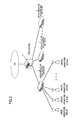
- Fig. 2 is a diagram depicting an embodiment of the mobile communication system.
- a plurality of mobile terminals are subordinate respectively to a plurality of base station BTSs (#1 to #n).
- An example of a plurality of base station BTSs (#1 to #n) is a micro-miniature base station to which at most several mobile terminals are subordinate respectively.
- a plurality of base station BTSs (#1 to #n) are connected to first base station control devices 2 (#1 to #n) corresponding to a predetermined number of base station BTSs (#1 to #n). And micro-miniature base station control devices (micro-miniature BTS control devices) are applied to the plurality of first base station control devices 2.
- the plurality of first base station control devices that is, micro-miniature BTS control devices 2 (#1 to #N) are connected to a second base station control device (RNC device) 1.
- This second base station control device that is, the RNC device 1 is a conventional base station control device, and is connected to a core network CN.
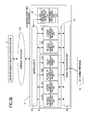
- Fig. 3A and Fig. 3B are diagrams depicting a configuration example and a connection example of the RNC device 1, micro-miniature BTS control device 2 and micro-miniature BTS device 3 in Fig. 2 respectively.
- Fig. 3A shows a connection between the RNC device 1 and micro-miniature BTS control device 2
- Fig. 3B shows a connection between the micro-miniature BTS control device 2 and micro-miniature BTS device 3.
- a core network (CN: core network: I in Fig. 3A ) is a generic phrase referring to a network or device that is higher than the RNC device 1 (II in Fig. 3A ) in the W-CDMA network, performing management of subscriber information, monitoring/managing each network device, and connecting with another network.
- the RNC device 1 is a device for controlling base stations, distributing signals of call control plane (C-Plane) data (including NBAP data) and user information transmission plane (U-Plane) data.
- C-Plane call control plane
- U-Plane user information transmission plane
- the micro-miniature BTS control device 2 (III in Fig. 3A ) is a device which can accommodate a plurality of micro-miniature BTS device 3 via the network 100, such as the Internet, and an interface (IF) with the RNC device 1 is the same as an interface with a regular base station device.
- the micro-miniature BTS control device 2 has an inter-RNC interface IF 20, C-Plane data processing unit 21, U-Plane data processing unit 22, NBAP signal processing unit 23, data storage unit 24 and inter-node interface IF 25 as the functional units.
- the inter-RNC interface IF 20 is an interface (IF) with the RNC device 1, and transmits/receives signals of the C-Plane data (including NBA data) and U-Plane data.
- the C-Plane data processing unit 21 receives a call control signal on a mobile terminal 10 (V in Fig. 3B ), which is sent from the RNC device 1, identifies the mobile terminal number, then sends the call control signal to the micro-miniature BTS device 3 to which this mobile terminal 10 is subordinate.
- the C-Plane data processing unit 21 also sends the C-Plane data which is sent from the micro-miniature BTS device 3 to the RNC device 1.
- An individual channel signal transmission/reception unit 210 transmits/receives a signal on an individual channel, out of the call control signals transmitted to/received from the RNC device 1.
- a common channel signal transmission/reception unit 211 transmits/receives a signal on a common channel, out of the call control signals transmitted to/received from the RNC device 1.
- An informative channel signal transmission/reception unit 212 transmits/receives a signal on an informative channel out of the call control signals transmitted to/received from the RNC device 1.
- a paging signal transmission/reception unit 213 transmits/receives a signal on a paging (call up) channel out of the call control signals transmitted to/received from the RNC device 1.
- a mobile terminal information acquisition unit 214 traces a signal of an individual/common channel transmitted to/received from the individual channel signal transmission/reception unit 210 and the common channel signal transmission/reception unit 211, and detects setup information on an individual channel which is set in a mobile terminal 10. Further, the mobile terminal information acquisition unit 214 records this information in a mobile terminal data base 240 of the data storage unit 24. When a call processing of the mobile terminal 10 ends, the mobile terminal information acquisition unit 214 deletes the setup information on an individual channel from the mobile terminal data base 240.
- a destination change unit 215A/215B determines, for the data transmitted from the RNC device 1, a user ID (UE-ID: User Equipment IDentification) and a micro-miniature BTS device 3 to which the mobile terminal 10 is subordinate, based on the mobile terminal data base 240 of the data storage unit 24, and sends the data to the address of this micro-miniature BTS device 3 based on a station data base 241 of the data storage unit 24.
- UE-ID User Equipment IDentification
- the destination of the data is changed to the address of the RNC device 1, and the data is transmitted again.
- a signal reproduction/destination change unit 216 reproduces the received informative signal since the informative signal must be transmitted to all the connected micro-miniature BTS devices 3, and sends the signal to the destinations written in the station data base 241 of the data storage unit 24.
- a signal shaping/destination change unit 217 extracts a paging on a mobile terminal 10 which is subordinate to a connected micro-miniature BTS device 3 from a paging signal received by the paging signal transmission/reception unit 213, shapes the paging to a paging signal in a unit of the micro-miniature BTS device 3, changes the destination to each micro-miniature BTS device 3, and transmits the signal.
- the U-Plane data processing unit 22 receives U-Plane data on a mobile terminal 10, which is sent from the RNC device 1, identifies the mobile terminal number, then sends the received data to a micro-miniature BTS device 3 to which this mobile terminal 10 is subordinate.
- the U-Plane data processing unit 22 also sends the U-Plane data sent from the micro-miniature BTS device 3 to the RNC device 1.
- An individual channel signal transmission/reception unit 220 transmits/receives U-Plane data of an individual channel.
- a common channel signal transmission/reception unit 221 transmits/receives U-Plane data of a common channel.
- a destination change unit 222A/222B determines, for the data transmitted from the RNC device 1, a user ID and a micro-miniature BTS device 3 to which the mobile terminal 10 is subordinate, based on the mobile terminal data base 240 of the data storage unit 24, and sends the data to the address of this micro-miniature BTS device 3 based on a station data base 241 of the data storage unit 24.
- the destination change unit 222A/222B changes the destination of the data to the address of the RNC device 1, and sends the data again.
- the NBAP signal processing unit 23 performs processing on an NBAP signal, which is a signal subject to base station control, out of C-Plane signals.
- An NBAP signal transmission/reception unit 230 of the NBAP signal processing unit 23 transmits/receives the NBAP signal.
- a destination change unit 231 determines, for the data transmitted from the RNC device 1, a target micro-miniature BTS device 3 based on the mobile terminal data base 240 of the data storage unit 24 and the station data base 241 of the data storage unit 24, and sends the data to the address of this micro-miniature BTS device 3. For the data received from the micro-miniature BTS device 3, the destination of the data is changed to the address of the RNC device 1, and the data is transmitted again.
- the data storage unit 24 stores two types of data: mobile terminal data base 240 and station data base 241.
- the mobile terminal data base 240 is a data base storing an identifier (user ID: UE-ID) of a mobile terminal 10, an IP address of this mobile terminal 10, an identification ID of a micro-miniature BTS device 3 to which the mobile terminal 10 is subordinate, and other information.
- This mobile terminal data base 240 is detected by a mobile terminal information acquisition unit, which is not illustrated, in the micro-miniature RNC control device 2, and is updated and recorded when necessary.
- the station data base 241 is a data base storing an identification ID and IP address of the micro-miniature BTS device 3, corresponding cell numbers and other information, and is recorded when the system is installed.
- the inter-node interface IF 25 is an interface IF with the micro-miniature BTS deice 3, and transmits/receives signals of the C-Plane data (including NBAP data), U-Plane data and other information.
- micro-miniature BTS device 3 (IV in Fig. 3 ) connected with the micro-miniature BTS control device 2 via the Internet network 100 and a configuration example thereof will be described.
- the micro-miniature BTS device 3 is a base station (BTS: Base Transceiver Station) which accommodates a plurality of mobile terminals 10, and the differences from a regular base station are as follows.
- BTS Base Transceiver Station
- the number of mobile terminals that can be accommodated is few (about 10 units).
- a regular base station can connect and accommodate several hundred mobile terminals.
- the number of cells is few (about 1 cell).
- a regular base station has around 3 to 24 cells.
- the radio wave coverage range is narrow (about several tens m). But is about 3 km in the case of a regular base station.
- the micro-miniature BTS device 3 has an inter-node interface IF 30, a C-Plane data processing unit 31, a U-Plane data processing unit 32, an NBAP signal processing unit 33 and a radio processing unit 34.
- the inter-node interface IF 30 is an interface IF with a micro-miniature BTS control device 2, and transmits/receives signals of the C-Plane data (including NBAP data), U-Plane data and other information.
- the C-Plane data processing unit 31 of the micro-miniature BTS device 3 receives a call control signal on a mobile terminal 10, which is sent from the micro-miniature BTS control device 2, and sends the signal to this mobile terminal 10.
- the C-Plane data processing unit 31 also sends C-Plane data, which is sent from a mobile terminal 10 to the micro-miniature BTS device 3, to the micro-miniature BTS control device 2.
- An individual channel signal transmission/reception unit 310 transmits/receives signals on an individual channel, out of call control signals which are transmitted to/received from the micro-miniature BTS control device 2.
- a common channel signal transmission/reception unit 311 transmits/receives signals on a common channel, out of the call control signals which are transmitted to/received from the micro-miniature BTS control device 2.
- An informative channel signal transmission/reception unit 312 transmits/receives signals on an informative channel, out of the call control signals which are transmitted from the micro-miniature BTS control device 2.
- a paging signal transmission/reception unit 313 transmits/receives signals on a paging (call up) channel, out of the call control signals which are transmitted from the micro-miniature BTS control device.
- the U-Plane data processing unit 32 receives U-Plane data on a mobile terminal 10, which is sent from the micro-miniature BTS control device 2, then sends the data to a mobile terminal 10.
- the U-Plane data processing unit 32 also sends U-Plane data sent from a mobile terminal 10 to the micro-miniature BTS control device 2.
- An individual channel signal transmission/reception unit 320 of the U-Plane data processing unit 32 transmits/receives U-Plane data of an individual channel.
- a common channel signal transmission/reception unit 321 transmits/receives the U-Plane data of a common channel.
- the NBAP signal processing unit 33 performs processing on an NBAP signal, which is a signal subject to base station control, out of C-Plane signals.
- An NBAP signal transmission/reception unit 330 of the NBAP signal processing unit 33 transmits/receives the NBAP signal.
- An NBAP signal processing unit 331 is a component which actually processes an NBAP signal (signal termination unit).
- Radio transmission/reception processing unit (RF/base band processing unit) 34]
- a radio transmission/reception processing unit 34 is an interface with a mobile terminal 10, and transmits/receives signals of C-Plane data and U-Plane data.
- a mobile terminal 10 is a terminal used by a user, and is a call processing termination component.
- the flow of signal processing is classified into the following four operations.
- transmission and other call control processing are performed between a mobile terminal 10 and RNC device 1 (or higher device).
- various signals are processed in the micro-miniature BTS device 3 and micro-miniature BTS control device 2.
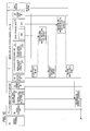
- Fig. 4A and Fig. 4B are diagrams depicting a sequence example among each device in (1) transmission and other call control processing from mobile terminal 10.
- the reference symbols Si to Sv show the flow of signals from the mobile terminal 10 to the RNC device 1.
- Si a transmission signal is sent from the mobile terminal 10 to a functional unit corresponding to the logical channel/transport channel, that is, a C-Plane or U-Plane data processing unit 31 and 32, via the radio processing unit 34 of the micro-miniature BTS device 3.
- header formats of MAC data PDU which is a signal to be transmitted, as shown in Fig. 5
- these header formats are used depending on the type of logical channel and transport channel, as the table in Fig. 6 shows.
- column V shows a reference number (1) to (6) in Fig. 5 at a position of a corresponding item.
- Fig. 7 shows a correspondence of a composing element of the header in Fig. 5 and its purpose. Description continues from Fig. 4A .
- the micro-miniature BTS device 3 receives the signal sent in Si using the C-plane or U-Plane data processing unit 31/32, which is a functional unit corresponding to a logical channel/transport channel. Then the micro-miniature BTS device 3 sends the received signal in MAC format to the inter-node interface IF 25 of the micro-miniature BTS control device 2 via the inter-node interface IF 30.
- the MAC format which is transmitted at this time, is shown in Fig. 5 , as described for Si.
- the transmission type between the micro-miniature BTS device 3 and the micro-miniature BTS control device 2 is IP packets at this time, addresses are attached such that the transmission source address becomes the micro-miniature BTS device 3, and the transmission destination address becomes the micro-miniature BTS control device 2.
- the micro-miniature BTS control device 2 receives the transmission signal in Sii using the inter-node interface IF 25, and sends it to the destination change unit 215A/B or 222A/B corresponding to the logical channel/transport channel.
- the transmission source address is changed to the micro-miniature BTS control device 2, and the transmission destination address is changed to the RNC device 1, and the signal is sent to a higher level transmission/receive units 210 to 212, 220 and 221.
- the mobile terminal information acquisition unit 214 acquires information to specify the mobile terminal 10 from the transmitted data, that is, information on UE-ID, address and individual channel, for example. Then the mobile terminal information acquisition unit 214 records the acquired information to specify the mobile terminal 10 to the mobile terminal data base 240 of the data storage unit 24. If the same data has been recorded, this recording is omitted. If there is a difference, the stored data is updated.
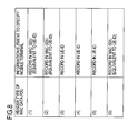
- MAC Data PDU For transmission data, there are six types of header formats of MAC Data PDU in Fig. 5 , as shown in Si, and the information to specify the mobile terminal 10 corresponds to the information element to specify a mobile terminal in the MAC Data PDU, as shown in the table in Fig. 8 , for example.
- the correspondence shown in Fig. 8 is an example, and if an ID is acquired by another method (using the mobile terminal ID for paging in the MAC SDU), the ID is recorded in the mobile terminal data base 240.
- the transmission type between the micro-miniature BTS control device 2 and the RNC device 1 is IP packets
- the transmission source address and the port number are also recorded in the mobile terminal data base 240. If information that a new individual channel (C-Plane/U-Plane) is set is included in the transmission data, UE-ID, IP address and port number of the newly set individual channel are recorded in the mobile terminal data base 240.
- FIG. 9 An example of the recording format of the mobile terminal data base 240 is shown in Fig. 9 .
- C-Plane/U-Plane If information that an individual channel (C-Plane/U-Plane) is deleted is included in the transmission data, information on the deleted individual channel is deleted from the mobile terminal data base 240. Even if information on all the individual addresses is deleted, the information on UE-ID itself (the first column in Fig. 9 ) is not deleted from the data base 240.
- Each channel signal transmission/reception unit which received the data in Sii replaces the transmission destination address with an address to the RNC device 1, and sends the receive data to the RNC device 1 via the inter-RNC interface IF 20.
- Fig. 4B is a diagram depicting the flow (Svi to Sx) of signals from the RNC device 1 to the mobile terminal 10. The signal flow will now be described with reference to Fig. 4B .
- a signal transmitted from the RNC device 1 is received by the channel transmission/reception unit 210/211, 220/221, corresponding to the logical channel/transport channel, via the inter-RNC interface IF 20 of the micro-miniature BTS control device 2, and is sent to the destination change unit 215A/B and 222A/B.
- Svii The destination change unit 210/211, 220/221, which received the transmission signal in Svi, performs processing similar to that in Siii.
- the transmission source address and port number are changed to the information on the micro-miniature BTS control device 2, and the transmission destination address and port number are changed to the address recorded in the mobile terminal data base 240 if the transmission type between the micro-miniature BTS control device 2 and micro-miniature BTS device 3 is IP packets. If there are a plurality of individual channel addresses, at this time, the transmission destination address is determined using the port number of the receive data.
- the data updated in Sviii is sent to the micro-miniature BTS device 3 via the inter-node interface IF 25.
- the micro-miniature BTS device receives the signal transmitted in Si via the inter-node interface IF 30, using the functional unit 31/32 corresponding to the logical channel/transport channel, and sends the signal to the mobile terminal 10 via the radio processing unit 30.
- paging (callup) processing to mobile terminal 10 processing to send the paging signal, which is transmitted from the RNC device 1, is sent to each micro-miniature BTS device 3.
- the paging signal here corresponds to "Paging Type 1 (TM: PCCH)" of the RRC message in 3GPP.
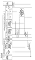
- Fig. 10 is a diagram depicting a sequence example among each device in (2) paging (callup) processing to mobile terminal 10.
- the reference symbols SIi to SIvii show the flow of signals from the RNC device 1 to the mobile terminal 10.
- a paging signal is sent from the RNC device 1 to the signal shaping/destination change unit 217 via the inter-RNC interface IF 20 in the micro-miniature BTS control device 2, through the paging signal receive unit 213 of the C-Plane data processing unit 21.
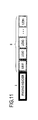
- FIG. 11 shows an image of a MAC SDU, where a plurality of terminal IDs (UE-ID) (II) after the paging header (I) are shown.
- UE-ID terminal IDs
- the signal shaping/destination change unit 217 decodes the paging signal, and extracts the terminal ID in the paging signal shown in Fig. 11 .
- SIiii The plurality of terminal IDs (UE-ID) extracted in SIii are collated with the mobile terminal data base 240 of the data storage unit 24, and if a mobile terminal 10 having the applicable ID (UE-ID) is included, the address of the micro-miniature BTS device 3, to which this mobile terminal 10 is subordinate, is acquired.
- UE-ID terminal IDs
- the address of the micro-miniature BTS control device 3 is "10.10.10.1" according to the example of the recording format of the mobile terminal data base 240 shown in Fig. 9 .
- SIiv Mobile terminals 10 which are subordinate to each micro-miniature BTS device 3 acquired in SIiii are sorted (separated), and a paging signal is created corresponding to the micro-miniature BTS device 3.
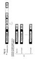
- the image after sorting is shown in Fig. 12 .
- an address (port number) for each micro-miniature BTS device 3 is attached after the paging header ((2) in Fig. 12 ).
- SIv If an uncollated mobile terminal ID (UE-ID), for which an address of the micro-miniature BTS device was not acquired, exists in SIiv, this uncollated mobile terminal ID (UE-ID) is added after the mobile terminal ID (UE-ID) sorted in SIiv in the paging signal.
- UE-ID uncollated mobile terminal ID
- a plurality of uncollated mobile terminal IDs are attached to the format image ((2) in Fig. 13 ) after the sorting shown in Fig. 12 ((3) in Fig. 13 ).
- the attached plurality of uncollated mobile terminal IDs are broadcasted among the micro-miniature BTS devices to which the mobile terminal IDs (UE-IDs) collated in SIiii, are subordinate.
- SIvi shows, when a plurality of uncollated terminal IDs (UE-IDs) are processed, the plurality of uncollated mobile terminal IDs (UE-IDs) are added only to an address of a micro-miniature BTS device to which the collated mobile terminal ID (UE-ID) is subordinate, and are broadcasted.
- UE-IDs uncollated terminal IDs
- UE-IDs uncollated mobile terminal IDs
- a micro-miniature BTS device to which the collated mobile terminal ID (UE-ID) is not subordinate, is called up.
- the addresses of the micro-miniature BTS devices which are not included in the micro-miniature BTS device list acquired in SIiii are acquired. Then the plurality of uncollated mobile terminal IDs (UE-IDs) are added so that these UE-IDs are broadcasted to the addresses of the micro-miniature BTS devices acquired in SIvi.
- UE-IDs uncollated mobile terminal IDs
- Fig. 14 shows the format image where the plurality of uncollated mobile terminal IDs (UE-IDs) are attached to the addresses of the micro-miniature BTS devices acquired in SIvi.
- UE-IDs uncollated mobile terminal IDs
- the micro-miniature BTS control device 2 sends the paging signals shown in Fig. 13 and Fig. 14 , where the uncollated mobile terminal IDs (UE-IDs) are attached in SIv, to the target micro-miniature BTS device 3 via the inter-node interface IF 25.
- the micro-miniature BTS device 3 sends the received paging signal to corresponding mobile terminals through the paging signal transmission/reception unit 313.
- an informative channel signal which is transmitted from the RNC device 1, is sent to each micro-miniature BTS device 3.
- Fig. 15 is a diagram depicting a sequence example among each device in (2) paging (callup) processing to mobile terminal 10.
- SIIi An informative channel signal is sent from the RNC device 1 to the informative channel signal reception unit 212 via the inter-RNC interface IF 20 in the micro-miniature BTS control device 2.
- the signal reproduction/destination change unit 216 acquires the IP address of the micro-miniature BTS device 3 in the station data base 241 of the data storage unit 24.
- SIIiii The informative signal is reproduced for a number of the acquired IP addresses.
- the reproduced informative signals are sent to all the acquired IP addresses of the micro-miniature BTS device 3 in the station data via the inter-node interface IF 25.
- SIIv The micro-miniature BTS device 3 which received the informative channel signal using the informative channel signal transmission/reception unit 312 via the inter-node interface IF 30 sends this signal to all the subordinate mobile terminals 10 via the radio processing unit 34.
- the NBAP signal sent from the RNC device 1 is sent to each micro-miniature BTS device 3.
- the NBAP signal is a protocol for processing a signal between the RNC device 1 and the base station (Node B).
- Typical examples of an NBAP signal are "radio link setup request”, “radio link setup response”, “establish request”, “establish confirm”, "radio link deletion request” and “radio link deletion response”.
- These signals are generated in the call processing step of the mobile terminal 10 (mainly used for such control as bearer addition/delete between the base station and mobile terminal 10). Therefore, in order to associate the call processing of the mobile terminal 10 and these NBAP signals, it is necessary to specify information related to the identifier ID of the mobile terminal 10 in the NBAP signal, and route the NBAP signal to the micro-miniature BTS device 3 to which the mobile terminal 10 is subordinate.
- Fig. 16A and Fig. 16B are diagrams depicting a sequence example among each device in (4) NBAP processing between micro-miniature BTS control device 2 and micro-miniature BTS device 3.
- Fig. 16A shows the flow of signals from the RNC device 1 to the micro-miniature BTS device 3 (SIIIi to SIIIv).
- Fig. 16B shows the flow of signals from the micro-miniature BTS device 3 to the RNC device 1 (SIIIvi to SIIIviii).
- the NBAP signal sent from the RNC device 1 is received by the NBAP signal transmission/reception unit 230 of the NBAP signal processing unit 23 via the inter-RNC interface IF 20 in the micro-miniature BTS control device 2, and is sent to the destination change unit 231.
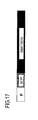
- Fig. 17 shows a format image of the NBAP signal, and shows a case when the transmission type between the micro-miniature BTS device 3 and micro-miniature BTS control device 2 is IP packets, which are transmitted/received via the Internet network 100.
- the destination change unit 231 which received the signal in SIIIi decodes the NBAP data, and acquires information to specify a mobile terminal 10, and extracts this mobile terminal 10 from the mobile terminal data base 240 of the data storage unit 24.
- SIIIiii The IP address and port number of the micro-miniature BTS device 3, to which the extracted mobile terminal 10 is subordinate, are acquired from the mobile terminal data base 240.
- SIIIiv The IP address and port number of the NBAP signal acquired in SIIIiii are replaced with those of the micro-miniature BTS device extracted in SIIIii, and sent to the micro-miniature BTS device 3 via the inter-node interface IF 25.
- the micro-miniature BTS device 3 receives the IP address and port number of the micro-miniature BTS device acquired in SIIIii, which replaced the IP address and port number acquired in SIIIiii, using the NBAP signal transmission/reception unit 330 of the NBAP signal processing unit 33 via the inter-node interface IF 30, and performs processing using the NBAP signal processing unit 331.
- the NBAP signal processing unit 331 sends an NBAP signal to the NBAP signal processing unit 23 in the micro-miniature BTS control device 2 via the NBAP signal transmission/reception unit 330 according to the processing result of the NBAP signal processing unit 331 in the NBAP processing unit 33 of the micro-miniature BTS device 3.
- the destination of the NBAP signal is changed to the address of the RNC device 1 by the address change unit 231 of the NBAP signal processing unit 33, which received the NBAP signal transmitted in SIIIvi.
- the destination change unit 231 changes the transmission source address of the NBAP signal received from the micro-miniature BTS device 3 to the micro-miniature BTS control device 2, and changes the transmission destination address thereof to the RNC device 1.
- the NBAP signal is sent via the NBAP signal transmission/reception unit 230.
- the NBAP signal transmission/reception unit 230 sends the received NBAP signal to the RNC device 1 via the inter-RNC interface IF 20.
- micro-miniature BTS devices 3 can be accommodated without modifying a conventional W-CDMA system, at los cost (by merely adding micro-miniature BTS control devices).
Landscapes
- Engineering & Computer Science (AREA)
- Computer Networks & Wireless Communication (AREA)
- Signal Processing (AREA)
- Databases & Information Systems (AREA)
- Mobile Radio Communication Systems (AREA)
Abstract
Description
- This application is based upon and claims the benefit of priority of the prior Japanese Patent Application No.
2008-070618, filed on March 19, 2008 - The present invention discussed herein is directed to a mobile communication system having a base station, and to a base station control device used in such a system.
- The spread of W-CDMA (Wideband Code Division Multiple System) type mobile communication systems is so obvious that the population coverage of W-CDMA type mobile communication system is nearly 100%. On the other hand, the coverage of W-CDMA type mobile communication system for indoor use is as yet not high. This is because radio waves do not easily enter from outdoors to indoors, and cost is high to install and operate a base station for indoor use.
- In this environment, a base station (BTS: Base Transceiver Station), called a "femto cell", which is smaller than a conventional base station, has recently been made available. It is assumed that this micro-miniature base station (hereafter called micro-miniature BTS device) will be used in a home or office, will support W-CDMA, enable simultaneous communication for about 4 users, and be inexpensive.
- By installing this micro-miniature BTS device in skyscrapers and in underground facilities which conventional base stations cannot fully cover, indoor coverage can be improved without increasing operation cost.
- However, for a general mobile communication system depicted as a related art in
Fig. 1 , to control base stations, it is necessary to manage base stations BTS #1, #2, ... #n by a base station control device (RNC: Radio Network Controller, hereafter called "RNC device") 1, which is connected to the core network CN. However the number of base stations BTS #1, #2, ... #n which oneRNC device 1 can control is limited, and this number is roughly several hundred. - First of all, a publically known technology is an invention disclosed in Japanese Laid-open Patent Publication No.
4-337997 - The invention disclosed in Japanese Laid-open Patent Publication No.
4-337997 - Another publically known technology is an invention disclosed in Japanese Laid-open Patent Publication No.
2004-179981 - Therefore, a new accommodating method is necessary to accommodate many (e.g. several thousand) micro-miniature BTS devices.
- With the foregoing in view, according to an aspect of the invention, a mobile communication system includes base stations and base station control devices, and has a plurality of base stations accommodating a plurality of mobile terminals respectively, a plurality of first base station control devices accommodating a predetermined number of base stations out of the above mentioned plurality of base stations respectively, and a second base station control device which accommodates the plurality of first base stations control devices. Each of the plurality of first base stations control devices further has, for supporting information to identify a mobile terminal, a mobile terminal data base which stores identification information on a base station to which a mobile terminal is subordinate, and a station data base which stores an address of the base station.
- Here, preferably, the plurality of base stations are micro-miniature base stations, and the plurality of first base station control devices are micro-miniature base station control devices, and the second base station control device is connected to a core network.
- The present invention also embraces a plurality of base station control devices used in such a system, as well as an individual such control device. The present invention also includes a mobile communication method, and software for enabling a processor of a wireless transceiver device to perform as the base station control device.
- It is to be understood that both the foregoing general description and the following detailed description are exemplary and explanatory only and are not restrictive of the invention, as claimed.
- It is to be understood that both the foregoing general description and the following detailed description are exemplary and explanatory only and are not restrictive of the invention, as claimed.
- Reference is made, by way of example only, to the accompanying drawings in which:
-
FIG. 1 shows a general mobile communication system; -
FIG. 2 is a diagram depicting an embodiment of the mobile communication system; -
FIG. 3A shows a connection between theRNC device 1 and micro-miniatureBTS control device 2; -
Fig. 3B shows a connection between the micro-miniatureBTS control device 2 andmicro-miniature BTS device 3; -
FIG. 4A is a diagram depicting a sequence example among each device in (1) transmission and other call control processing frommobile terminal 10 and shows the flow of signals from themobile terminal 10 to theRNC device 1; -
FIG. 4B is a diagram depicting a sequence example among each device in (1) transmission and other call control processing from theRNC device 1 tomobile terminal 10; -
FIG. 5 shows an example of the header format of MAC Data PDU, which is a signal to be transmitted; -
FIG. 6 shows a table where the six types of header formats of MAC data PDU are used depending on the type of logical channel and transport channel as shown inFIG. 5 ; -
FIG. 7 shows a correspondence of a composing element of the header inFIG. 5 and its purpose; -
FIG. 8 is a diagram depicting the information to specify themobile terminal 10 corresponds to the information element to specify a mobile terminal in the MAC Data PDU; -
FIG. 9 is an example of the recording format of the mobileterminal data base 240; -
FIG. 10 is a diagram depicting a sequence example among each device in (2) paging (callup) processing tomobile terminal 10; -
FIG. 11 shows an image of the paging signal; -
FIG. 12 shows the image of the paging signal after sorting; -
FIG. 13 is an example of image after addition where uncollated mobile terminal IDs (UE-IDs) are attached to the format image after the sorting; -
FIG. 14 shows the format image where the plurality of uncollated mobile terminal IDs (UE-IDs) are attached to the addresses of the micro-miniature BTS devices; -
FIG. 15 is a diagram depicting a sequence example among each device in (2) paging (callup) processing tomobile terminal 10; -
Fig. 16A is a diagram depicting a sequence example among each device in (4) NBAP processing between micro-miniatureBTS control device 2 andmicro-miniature BTS device 3 and shows the flow of signals from theRNC device 1 to themicro-miniature BTS device 3. -
FIG. 16B is a diagram depicting a sequence example among each device in (4) NBAP processing between micro-miniatureBTS control device 2 andmicro-miniature BTS device 3 and shows the flow of signals from themicro-miniature BTS device 3 to theRNC device 1; and -
Fig. 17 shows a format image of the NBAP signal. - Embodiments will now be described with reference to the drawings.
-
Fig. 2 is a diagram depicting an embodiment of the mobile communication system. - A plurality of mobile terminals are subordinate respectively to a plurality of base station BTSs (#1 to #n). An example of a plurality of base station BTSs (#1 to #n) is a micro-miniature base station to which at most several mobile terminals are subordinate respectively.
- A plurality of base station BTSs (#1 to #n) are connected to first base station control devices 2 (#1 to #n) corresponding to a predetermined number of base station BTSs (#1 to #n). And micro-miniature base station control devices (micro-miniature BTS control devices) are applied to the plurality of first base
station control devices 2. - The plurality of first base station control devices, that is, micro-miniature BTS control devices 2 (#1 to #N) are connected to a second base station control device (RNC device) 1. This second base station control device, that is, the
RNC device 1, is a conventional base station control device, and is connected to a core network CN. -
Fig. 3A andFig. 3B are diagrams depicting a configuration example and a connection example of theRNC device 1, micro-miniatureBTS control device 2 andmicro-miniature BTS device 3 inFig. 2 respectively.Fig. 3A shows a connection between theRNC device 1 and micro-miniatureBTS control device 2, andFig. 3B shows a connection between the micro-miniatureBTS control device 2 andmicro-miniature BTS device 3. - In
Fig. 3A , a core network (CN: core network: I inFig. 3A ) is a generic phrase referring to a network or device that is higher than the RNC device 1 (II inFig. 3A ) in the W-CDMA network, performing management of subscriber information, monitoring/managing each network device, and connecting with another network. - The
RNC device 1 is a device for controlling base stations, distributing signals of call control plane (C-Plane) data (including NBAP data) and user information transmission plane (U-Plane) data. - The micro-miniature BTS control device 2 (III in
Fig. 3A ) is a device which can accommodate a plurality ofmicro-miniature BTS device 3 via thenetwork 100, such as the Internet, and an interface (IF) with theRNC device 1 is the same as an interface with a regular base station device. - The micro-miniature
BTS control device 2 has an inter-RNC interface IF 20, C-Planedata processing unit 21, U-Planedata processing unit 22, NBAPsignal processing unit 23,data storage unit 24 and inter-node interface IF 25 as the functional units. - The inter-RNC interface IF 20 is an interface (IF) with the
RNC device 1, and transmits/receives signals of the C-Plane data (including NBA data) and U-Plane data. - The C-Plane
data processing unit 21 receives a call control signal on a mobile terminal 10 (V inFig. 3B ), which is sent from theRNC device 1, identifies the mobile terminal number, then sends the call control signal to themicro-miniature BTS device 3 to which thismobile terminal 10 is subordinate. The C-Planedata processing unit 21 also sends the C-Plane data which is sent from themicro-miniature BTS device 3 to theRNC device 1. - Now each functional unit of the C-Plane
data processing unit 21 will be described. - An individual channel signal transmission/
reception unit 210 transmits/receives a signal on an individual channel, out of the call control signals transmitted to/received from theRNC device 1. - A common channel signal transmission/
reception unit 211 transmits/receives a signal on a common channel, out of the call control signals transmitted to/received from theRNC device 1. - An informative channel signal transmission/
reception unit 212 transmits/receives a signal on an informative channel out of the call control signals transmitted to/received from theRNC device 1. - A paging signal transmission/
reception unit 213 transmits/receives a signal on a paging (call up) channel out of the call control signals transmitted to/received from theRNC device 1. - A mobile terminal
information acquisition unit 214 traces a signal of an individual/common channel transmitted to/received from the individual channel signal transmission/reception unit 210 and the common channel signal transmission/reception unit 211, and detects setup information on an individual channel which is set in amobile terminal 10. Further, the mobile terminalinformation acquisition unit 214 records this information in a mobileterminal data base 240 of thedata storage unit 24. When a call processing of themobile terminal 10 ends, the mobile terminalinformation acquisition unit 214 deletes the setup information on an individual channel from the mobileterminal data base 240. - A
destination change unit 215A/215B determines, for the data transmitted from theRNC device 1, a user ID (UE-ID: User Equipment IDentification) and amicro-miniature BTS device 3 to which themobile terminal 10 is subordinate, based on the mobileterminal data base 240 of thedata storage unit 24, and sends the data to the address of thismicro-miniature BTS device 3 based on astation data base 241 of thedata storage unit 24. - For the data received from the micro-miniature BTS device 3 (IV in
Fig. 3B ), the destination of the data is changed to the address of theRNC device 1, and the data is transmitted again. - A signal reproduction/
destination change unit 216 reproduces the received informative signal since the informative signal must be transmitted to all the connectedmicro-miniature BTS devices 3, and sends the signal to the destinations written in thestation data base 241 of thedata storage unit 24. - A signal shaping/
destination change unit 217 extracts a paging on amobile terminal 10 which is subordinate to a connectedmicro-miniature BTS device 3 from a paging signal received by the paging signal transmission/reception unit 213, shapes the paging to a paging signal in a unit of themicro-miniature BTS device 3, changes the destination to eachmicro-miniature BTS device 3, and transmits the signal. - The U-Plane
data processing unit 22 receives U-Plane data on amobile terminal 10, which is sent from theRNC device 1, identifies the mobile terminal number, then sends the received data to amicro-miniature BTS device 3 to which thismobile terminal 10 is subordinate. The U-Planedata processing unit 22 also sends the U-Plane data sent from themicro-miniature BTS device 3 to theRNC device 1. - Now each functional unit of the U-Plane
data processing unit 22 will be described. - An individual channel signal transmission/
reception unit 220 transmits/receives U-Plane data of an individual channel. A common channel signal transmission/reception unit 221 transmits/receives U-Plane data of a common channel. - A
destination change unit 222A/222B determines, for the data transmitted from theRNC device 1, a user ID and amicro-miniature BTS device 3 to which themobile terminal 10 is subordinate, based on the mobileterminal data base 240 of thedata storage unit 24, and sends the data to the address of thismicro-miniature BTS device 3 based on astation data base 241 of thedata storage unit 24. For the data received from themicro-miniature BTS device 3, thedestination change unit 222A/222B changes the destination of the data to the address of theRNC device 1, and sends the data again. - The NBAP
signal processing unit 23 performs processing on an NBAP signal, which is a signal subject to base station control, out of C-Plane signals. An NBAP signal transmission/reception unit 230 of the NBAPsignal processing unit 23 transmits/receives the NBAP signal. - A
destination change unit 231 determines, for the data transmitted from theRNC device 1, a targetmicro-miniature BTS device 3 based on the mobileterminal data base 240 of thedata storage unit 24 and thestation data base 241 of thedata storage unit 24, and sends the data to the address of thismicro-miniature BTS device 3. For the data received from themicro-miniature BTS device 3, the destination of the data is changed to the address of theRNC device 1, and the data is transmitted again. - The
data storage unit 24 stores two types of data: mobileterminal data base 240 andstation data base 241. - The mobile
terminal data base 240 is a data base storing an identifier (user ID: UE-ID) of amobile terminal 10, an IP address of thismobile terminal 10, an identification ID of amicro-miniature BTS device 3 to which themobile terminal 10 is subordinate, and other information. This mobileterminal data base 240 is detected by a mobile terminal information acquisition unit, which is not illustrated, in the micro-miniatureRNC control device 2, and is updated and recorded when necessary. - The
station data base 241 is a data base storing an identification ID and IP address of themicro-miniature BTS device 3, corresponding cell numbers and other information, and is recorded when the system is installed. - The inter-node interface IF 25 is an interface IF with the
micro-miniature BTS deice 3, and transmits/receives signals of the C-Plane data (including NBAP data), U-Plane data and other information. - Now a micro-miniature BTS device 3 (IV in
Fig. 3 ) connected with the micro-miniatureBTS control device 2 via theInternet network 100 and a configuration example thereof will be described. - The
micro-miniature BTS device 3 is a base station (BTS: Base Transceiver Station) which accommodates a plurality ofmobile terminals 10, and the differences from a regular base station are as follows. - The number of mobile terminals that can be accommodated is few (about 10 units). A regular base station can connect and accommodate several hundred mobile terminals.
- The number of cells is few (about 1 cell). A regular base station has around 3 to 24 cells.
- The radio wave coverage range is narrow (about several tens m). But is about 3 km in the case of a regular base station.
- The
micro-miniature BTS device 3 has an inter-node interface IF 30, a C-Planedata processing unit 31, a U-Planedata processing unit 32, an NBAPsignal processing unit 33 and aradio processing unit 34. - Now each functional unit of the
micro-miniature BTS device 3 will be described in details. - The inter-node interface IF 30 is an interface IF with a micro-miniature
BTS control device 2, and transmits/receives signals of the C-Plane data (including NBAP data), U-Plane data and other information. - The C-Plane
data processing unit 31 of themicro-miniature BTS device 3 receives a call control signal on amobile terminal 10, which is sent from the micro-miniatureBTS control device 2, and sends the signal to thismobile terminal 10. The C-Planedata processing unit 31 also sends C-Plane data, which is sent from amobile terminal 10 to themicro-miniature BTS device 3, to the micro-miniatureBTS control device 2. - Operations of the functional units of the C-Plane
data processing unit 31 are as follows. - An individual channel signal transmission/
reception unit 310 transmits/receives signals on an individual channel, out of call control signals which are transmitted to/received from the micro-miniatureBTS control device 2. - A common channel signal transmission/
reception unit 311 transmits/receives signals on a common channel, out of the call control signals which are transmitted to/received from the micro-miniatureBTS control device 2. - An informative channel signal transmission/
reception unit 312 transmits/receives signals on an informative channel, out of the call control signals which are transmitted from the micro-miniatureBTS control device 2. - A paging signal transmission/
reception unit 313 transmits/receives signals on a paging (call up) channel, out of the call control signals which are transmitted from the micro-miniature BTS control device. - The U-Plane
data processing unit 32 receives U-Plane data on amobile terminal 10, which is sent from the micro-miniatureBTS control device 2, then sends the data to amobile terminal 10. The U-Planedata processing unit 32 also sends U-Plane data sent from amobile terminal 10 to the micro-miniatureBTS control device 2. - An individual channel signal transmission/
reception unit 320 of the U-Planedata processing unit 32 transmits/receives U-Plane data of an individual channel. A common channel signal transmission/reception unit 321 transmits/receives the U-Plane data of a common channel. - The NBAP
signal processing unit 33 performs processing on an NBAP signal, which is a signal subject to base station control, out of C-Plane signals. - An NBAP signal transmission/
reception unit 330 of the NBAPsignal processing unit 33 transmits/receives the NBAP signal. An NBAPsignal processing unit 331 is a component which actually processes an NBAP signal (signal termination unit). - A radio transmission/
reception processing unit 34 is an interface with amobile terminal 10, and transmits/receives signals of C-Plane data and U-Plane data. [Mobile terminal 10] - A
mobile terminal 10 is a terminal used by a user, and is a call processing termination component. - A flow of signal processing in the configuration of the above mentioned embodiment of the mobile communication system will now be described.
- The flow of signal processing is classified into the following four operations.
- These four signal processing operations respectively will now be described in detail.
- In (1) transmissions and other call control processing from
mobile terminal 10, transmission and other call control processing are performed between amobile terminal 10 and RNC device 1 (or higher device). In this case, various signals are processed in themicro-miniature BTS device 3 and micro-miniatureBTS control device 2. -
Fig. 4A andFig. 4B are diagrams depicting a sequence example among each device in (1) transmission and other call control processing frommobile terminal 10. - In
Fig. 4A , the reference symbols Si to Sv show the flow of signals from themobile terminal 10 to theRNC device 1. - Si: a transmission signal is sent from the
mobile terminal 10 to a functional unit corresponding to the logical channel/transport channel, that is, a C-Plane or U-Planedata processing unit radio processing unit 34 of themicro-miniature BTS device 3. - There are 6 types of header formats of MAC data PDU, which is a signal to be transmitted, as shown in
Fig. 5 , and these header formats are used depending on the type of logical channel and transport channel, as the table inFig. 6 shows. - In the table in
Fig. 6 , column V shows a reference number (1) to (6) inFig. 5 at a position of a corresponding item.Fig. 7 shows a correspondence of a composing element of the header inFig. 5 and its purpose. Description continues fromFig. 4A . - Sii: The
micro-miniature BTS device 3 receives the signal sent in Si using the C-plane or U-Planedata processing unit 31/32, which is a functional unit corresponding to a logical channel/transport channel. Then themicro-miniature BTS device 3 sends the received signal in MAC format to the inter-node interface IF 25 of the micro-miniatureBTS control device 2 via the inter-node interface IF 30. The MAC format, which is transmitted at this time, is shown inFig. 5 , as described for Si. - If the transmission type between the
micro-miniature BTS device 3 and the micro-miniatureBTS control device 2 is IP packets at this time, addresses are attached such that the transmission source address becomes themicro-miniature BTS device 3, and the transmission destination address becomes the micro-miniatureBTS control device 2. - Siii: Then the micro-miniature
BTS control device 2 receives the transmission signal in Sii using the inter-node interface IF 25, and sends it to thedestination change unit 215A/B or 222A/B corresponding to the logical channel/transport channel. - If the transmission type between the micro-miniature
BTS control device 2 and theRNC device 1 is IP packets at this time, the transmission source address is changed to the micro-miniatureBTS control device 2, and the transmission destination address is changed to theRNC device 1, and the signal is sent to a higher level transmission/receiveunits 210 to 212, 220 and 221. - Siv: During the processing in Siii, the mobile terminal
information acquisition unit 214 acquires information to specify the mobile terminal 10 from the transmitted data, that is, information on UE-ID, address and individual channel, for example. Then the mobile terminalinformation acquisition unit 214 records the acquired information to specify themobile terminal 10 to the mobileterminal data base 240 of thedata storage unit 24. If the same data has been recorded, this recording is omitted. If there is a difference, the stored data is updated. - For transmission data, there are six types of header formats of MAC Data PDU in
Fig. 5 , as shown in Si, and the information to specify themobile terminal 10 corresponds to the information element to specify a mobile terminal in the MAC Data PDU, as shown in the table inFig. 8 , for example. - The correspondence shown in
Fig. 8 is an example, and if an ID is acquired by another method (using the mobile terminal ID for paging in the MAC SDU), the ID is recorded in the mobileterminal data base 240. - If the transmission type between the micro-miniature
BTS control device 2 and theRNC device 1 is IP packets, the transmission source address and the port number are also recorded in the mobileterminal data base 240. If information that a new individual channel (C-Plane/U-Plane) is set is included in the transmission data, UE-ID, IP address and port number of the newly set individual channel are recorded in the mobileterminal data base 240. - An example of the recording format of the mobile
terminal data base 240 is shown inFig. 9 . - If information that an individual channel (C-Plane/U-Plane) is deleted is included in the transmission data, information on the deleted individual channel is deleted from the mobile
terminal data base 240. Even if information on all the individual addresses is deleted, the information on UE-ID itself (the first column inFig. 9 ) is not deleted from thedata base 240. - Sv: Each channel signal transmission/reception unit which received the data in Sii replaces the transmission destination address with an address to the
RNC device 1, and sends the receive data to theRNC device 1 via the inter-RNC interface IF 20. -
Fig. 4B is a diagram depicting the flow (Svi to Sx) of signals from theRNC device 1 to themobile terminal 10. The signal flow will now be described with reference toFig. 4B . - Svi: A signal transmitted from the
RNC device 1 is received by the channel transmission/reception unit 210/211, 220/221, corresponding to the logical channel/transport channel, via the inter-RNC interface IF 20 of the micro-miniatureBTS control device 2, and is sent to thedestination change unit 215A/B and 222A/B. - Svii: The
destination change unit 210/211, 220/221, which received the transmission signal in Svi, performs processing similar to that in Siii. - Sviii: Based on the user ID (UE-ID) specified in Svii, the transmission source address and port number are changed to the information on the micro-miniature
BTS control device 2, and the transmission destination address and port number are changed to the address recorded in the mobileterminal data base 240 if the transmission type between the micro-miniatureBTS control device 2 andmicro-miniature BTS device 3 is IP packets. If there are a plurality of individual channel addresses, at this time, the transmission destination address is determined using the port number of the receive data. - Six: The data updated in Sviii is sent to the
micro-miniature BTS device 3 via the inter-node interface IF 25. - Sx: The micro-miniature BTS device receives the signal transmitted in Si via the inter-node interface IF 30, using the
functional unit 31/32 corresponding to the logical channel/transport channel, and sends the signal to themobile terminal 10 via theradio processing unit 30. - In (2) paging (callup) processing to
mobile terminal 10, processing to send the paging signal, which is transmitted from theRNC device 1, is sent to eachmicro-miniature BTS device 3. The paging signal here corresponds to "Paging Type 1 (TM: PCCH)" of the RRC message in 3GPP. -
Fig. 10 is a diagram depicting a sequence example among each device in (2) paging (callup) processing tomobile terminal 10. InFig. 10 , the reference symbols SIi to SIvii show the flow of signals from theRNC device 1 to themobile terminal 10. - SIi: A paging signal is sent from the
RNC device 1 to the signal shaping/destination change unit 217 via the inter-RNC interface IF 20 in the micro-miniatureBTS control device 2, through the paging signal receiveunit 213 of the C-Planedata processing unit 21. - An image of the paging signal is shown in
Fig. 11. Fig. 11 shows an image of a MAC SDU, where a plurality of terminal IDs (UE-ID) (II) after the paging header (I) are shown. - SIii: The signal shaping/
destination change unit 217 decodes the paging signal, and extracts the terminal ID in the paging signal shown inFig. 11 . - SIiii: The plurality of terminal IDs (UE-ID) extracted in SIii are collated with the mobile
terminal data base 240 of thedata storage unit 24, and if amobile terminal 10 having the applicable ID (UE-ID) is included, the address of themicro-miniature BTS device 3, to which thismobile terminal 10 is subordinate, is acquired. - For example, if the terminal ID is UE = 000001, the address of the micro-miniature
BTS control device 3 is "10.10.10.1" according to the example of the recording format of the mobileterminal data base 240 shown inFig. 9 . - SIiv:
Mobile terminals 10 which are subordinate to eachmicro-miniature BTS device 3 acquired in SIiii are sorted (separated), and a paging signal is created corresponding to themicro-miniature BTS device 3. - The image after sorting is shown in
Fig. 12 . Compared with the source data (1) corresponding to the paging signal image inFig. 11 , an address (port number) for eachmicro-miniature BTS device 3 is attached after the paging header ((2) inFig. 12 ). - SIv: If an uncollated mobile terminal ID (UE-ID), for which an address of the micro-miniature BTS device was not acquired, exists in SIiv, this uncollated mobile terminal ID (UE-ID) is added after the mobile terminal ID (UE-ID) sorted in SIiv in the paging signal.
- An image after this addition is shown in
Fig. 13 . InFig. 13 , a plurality of uncollated mobile terminal IDs (UE-IDs) are attached to the format image ((2) inFig. 13 ) after the sorting shown inFig. 12 ((3) inFig. 13 ). Thereby the attached plurality of uncollated mobile terminal IDs (UE-IDs), are broadcasted among the micro-miniature BTS devices to which the mobile terminal IDs (UE-IDs) collated in SIiii, are subordinate. - SIvi: As SIv shows, when a plurality of uncollated terminal IDs (UE-IDs) are processed, the plurality of uncollated mobile terminal IDs (UE-IDs) are added only to an address of a micro-miniature BTS device to which the collated mobile terminal ID (UE-ID) is subordinate, and are broadcasted.
- It is also possible that a micro-miniature BTS device, to which the collated mobile terminal ID (UE-ID) is not subordinate, is called up.
- Therefore, in order to perfect paging processing, the addresses of the micro-miniature BTS devices which are not included in the micro-miniature BTS device list acquired in SIiii (see
Fig. 12 ) are acquired. Then the plurality of uncollated mobile terminal IDs (UE-IDs) are added so that these UE-IDs are broadcasted to the addresses of the micro-miniature BTS devices acquired in SIvi. -
Fig. 14 shows the format image where the plurality of uncollated mobile terminal IDs (UE-IDs) are attached to the addresses of the micro-miniature BTS devices acquired in SIvi. - SIvii: Again referring to
Fig. 10 , the micro-miniatureBTS control device 2 sends the paging signals shown inFig. 13 andFig. 14 , where the uncollated mobile terminal IDs (UE-IDs) are attached in SIv, to the targetmicro-miniature BTS device 3 via the inter-node interface IF 25. Themicro-miniature BTS device 3 sends the received paging signal to corresponding mobile terminals through the paging signal transmission/reception unit 313. - In (3) informative data processing to
mobile terminal 10, an informative channel signal, which is transmitted from theRNC device 1, is sent to eachmicro-miniature BTS device 3. -
Fig. 15 is a diagram depicting a sequence example among each device in (2) paging (callup) processing tomobile terminal 10. - SIIi: An informative channel signal is sent from the
RNC device 1 to the informative channelsignal reception unit 212 via the inter-RNC interface IF 20 in the micro-miniatureBTS control device 2. - SIIii: Based on the received informative channel signal by the informative channel
signal reception unit 212, the signal reproduction/destination change unit 216 acquires the IP address of themicro-miniature BTS device 3 in thestation data base 241 of thedata storage unit 24. - SIIiii: The informative signal is reproduced for a number of the acquired IP addresses.
- SIIiv: The reproduced informative signals are sent to all the acquired IP addresses of the
micro-miniature BTS device 3 in the station data via the inter-node interface IF 25. - SIIv: The
micro-miniature BTS device 3 which received the informative channel signal using the informative channel signal transmission/reception unit 312 via the inter-node interface IF 30 sends this signal to all the subordinatemobile terminals 10 via theradio processing unit 34. - In (4) NBAP processing between the micro-miniature
BTS control device 2 andmicro-miniature BTS device 3, the NBAP signal sent from theRNC device 1 is sent to eachmicro-miniature BTS device 3. - Here the NBAP signal is a protocol for processing a signal between the
RNC device 1 and the base station (Node B). Typical examples of an NBAP signal are "radio link setup request", "radio link setup response", "establish request", "establish confirm", "radio link deletion request" and "radio link deletion response". - These signals are generated in the call processing step of the mobile terminal 10 (mainly used for such control as bearer addition/delete between the base station and mobile terminal 10). Therefore, in order to associate the call processing of the
mobile terminal 10 and these NBAP signals, it is necessary to specify information related to the identifier ID of themobile terminal 10 in the NBAP signal, and route the NBAP signal to themicro-miniature BTS device 3 to which themobile terminal 10 is subordinate. - Therefore, in the following processing content, a processing to extract information on the mobile terminal 10 from the NBAP signal data is performed, in order to implement processing of the NBAP signal appropriately.
-
Fig. 16A andFig. 16B are diagrams depicting a sequence example among each device in (4) NBAP processing between micro-miniatureBTS control device 2 andmicro-miniature BTS device 3. -
Fig. 16A shows the flow of signals from theRNC device 1 to the micro-miniature BTS device 3 (SIIIi to SIIIv).Fig. 16B shows the flow of signals from themicro-miniature BTS device 3 to the RNC device 1 (SIIIvi to SIIIviii). - SIIIi: In
Fig. 16A , the NBAP signal sent from theRNC device 1 is received by the NBAP signal transmission/reception unit 230 of the NBAPsignal processing unit 23 via the inter-RNC interface IF 20 in the micro-miniatureBTS control device 2, and is sent to thedestination change unit 231. -
Fig. 17 shows a format image of the NBAP signal, and shows a case when the transmission type between themicro-miniature BTS device 3 and micro-miniatureBTS control device 2 is IP packets, which are transmitted/received via theInternet network 100. - SIIIii: The
destination change unit 231 which received the signal in SIIIi decodes the NBAP data, and acquires information to specify amobile terminal 10, and extracts this mobile terminal 10 from the mobileterminal data base 240 of thedata storage unit 24. - SIIIiii: The IP address and port number of the
micro-miniature BTS device 3, to which the extractedmobile terminal 10 is subordinate, are acquired from the mobileterminal data base 240. - SIIIiv: The IP address and port number of the NBAP signal acquired in SIIIiii are replaced with those of the micro-miniature BTS device extracted in SIIIii, and sent to the
micro-miniature BTS device 3 via the inter-node interface IF 25. - SIIIv: The
micro-miniature BTS device 3 receives the IP address and port number of the micro-miniature BTS device acquired in SIIIii, which replaced the IP address and port number acquired in SIIIiii, using the NBAP signal transmission/reception unit 330 of the NBAPsignal processing unit 33 via the inter-node interface IF 30, and performs processing using the NBAPsignal processing unit 331. - SIIIvi: IN
Fig. 16B , the NBAPsignal processing unit 331 sends an NBAP signal to the NBAPsignal processing unit 23 in the micro-miniatureBTS control device 2 via the NBAP signal transmission/reception unit 330 according to the processing result of the NBAPsignal processing unit 331 in theNBAP processing unit 33 of themicro-miniature BTS device 3. - SIIIvii: The destination of the NBAP signal is changed to the address of the
RNC device 1 by theaddress change unit 231 of the NBAPsignal processing unit 33, which received the NBAP signal transmitted in SIIIvi. In other words, thedestination change unit 231 changes the transmission source address of the NBAP signal received from themicro-miniature BTS device 3 to the micro-miniatureBTS control device 2, and changes the transmission destination address thereof to theRNC device 1. Then the NBAP signal is sent via the NBAP signal transmission/reception unit 230. - SIIIviii: The NBAP signal transmission/
reception unit 230 sends the received NBAP signal to theRNC device 1 via the inter-RNC interface IF 20. - As described above, according to the present invention, many
micro-miniature BTS devices 3 can be accommodated without modifying a conventional W-CDMA system, at los cost (by merely adding micro-miniature BTS control devices). - All examples and conditional language recited herein are intended for pedagogical purposes to aid the reader in understanding the principles of the invention and the concepts contributed by the inventor to furthering the art, and are to be construed as being without limitation to such specifically recited examples and conditions, nor does the organization of such examples in the specification relate to a showing of the superiority and inferiority of the invention. Although the embodiments of the present invention has been described in detail, it should be understood that the various changes, substitutions, and alterations could be made hereto without departing from the scope of the invention.
Claims (15)
- A mobile communication system, comprising:a plurality of base stations which accommodate a plurality of mobile terminals respectively;a plurality of first base station control devices, each of which accommodates a predetermined number of base stations out of the plurality of base stations; anda second base station control device which accommodates the plurality of first base station control devices, whereineach of the plurality of first base station control devices comprises, for supporting information identifying a mobile terminal, a mobile terminal data base to store identification information which identifies a base station to which the mobile terminal is subordinate, and a station data base to store an address of the base station.
- The mobile communication system according to claim 1, wherein the plurality of base stations are micro-miniature base stations, and the plurality of first base station control devices are micro-miniature base station control devices, and the second base station control device is connected to a core network.
- The mobile communication system according to claim 2, wherein in order to support information to identify a mobile terminal stored in the mobile terminal data base, the identification information on a base station to which the mobile terminal is subordinate is extracted based on a transmission data format, which is used when a signal is transmitted from the mobile terminal to the second base station control device.
- The mobile communication system according to Claim 3, wherein
when a signal is transmitted from the mobile terminal to the second base station control device, the first base station control device regards a transmission source address as the base station, and a transmission destination address as the first base station control device if a transmission type, between the base station and the first base station control device, is based on IP packets, and the first base station control device replaces the transmission destination address with an address of the second base station control device, and transmits the data received from the base station. - A plurality of base station control devices, in a mobile communication system including a plurality of base stations accommodating a plurality of mobile terminals and one base station control device connected to a core network, which are installed separately from the one base station control device connected to the core network, and which accommodate a predetermined number of base stations out of the plurality of base stations, wherein
each of the plurality of base station control devices comprises, for supporting information to identify the mobile terminal, a mobile terminal data base, which stores identification information on a base station to which the mobile terminal is subordinate, and a station data base which stores an address of the base station. - The plurality of devices according to Claim 5, wherein
the plurality of base stations are micro-miniature base stations, and each base station control device is a micro-miniature base station control device that supports the micro-miniature base stations. - A micro-miniature base station control device used as one of the plurality of devices according to claim 6.
- The micro-miniature base station control device according to Claim 7, arranged such that, in order to support information to identify a mobile terminal stored in the mobile terminal data base, the identification information on a base station to which the mobile terminal is subordinate is extracted based on a transmission data format which is used when a signal is transmitted from the mobile terminal.
- The micro-miniature base station control device according to Claim 8, arranged such that
when a signal is transmitted from the mobile terminal to one base station control device connected to the core network, a transmission source address is regarded as the base station and a transmission destination address is regarded as the base station control device if a transmission type with the base station is based on IP packets, and the base station control device replaces the transmission destination address with an address of the one base station control device connected to the core network, and transmits the data received from the base station. - The micro-miniature base station control device according to Claim 9, arranged such that a call control signal exchanged with a mobile terminal can be transmitted or received among the mobile terminal, the base station control device and the core network.
- The micro-miniature base station control device according to Claim 9 or 10, arranged such that a user data signal exchanged with a mobile terminal can be transmitted or received among the mobile terminal, the base station control device and the core network.
- The micro-miniature base station control device according to Claim 9, 10, or 11, arranged such that informative data, to be transmitted to all the mobile terminals which are subordinate to the micro-miniature base station control device, can be transmitted among the mobile terminals, the base station control device and the core network.
- The micro-miniature base station control device according to any of Claims 9 to 12, arranged such that a base station control signal to the micro-miniature base station can be transmitted or received between the micro-miniature base station and the base station control device.
- The micro-miniature base station control device according to any of Claims 9 to 13, arranged such that a paging signal, to be transmitted to the micro-miniature base station control device, is optimized and transmitted to the micro-miniature base station based on the mobile terminal data base so that the paging signal is transmitted only to the mobile terminal which is subordinate to the micro-miniature base station.
- The micro-miniature base station control device according to Claim 13, arranged such that when a paging signal is received from a mobile terminal which does not exist in the mobile terminal data base, the paging signal addressed to the mobile terminal is transmitted to all of the micro-miniature base stations to which the mobile terminal is subordinate.
Applications Claiming Priority (1)
| Application Number | Priority Date | Filing Date | Title |
|---|---|---|---|
| JP2008070618A JP5194915B2 (en) | 2008-03-19 | 2008-03-19 | Mobile communication system |
Publications (2)
| Publication Number | Publication Date |
|---|---|
| EP2104398A1 true EP2104398A1 (en) | 2009-09-23 |
| EP2104398B1 EP2104398B1 (en) | 2013-05-01 |
Family
ID=40394167
Family Applications (1)
| Application Number | Title | Priority Date | Filing Date |
|---|---|---|---|
| EP20080167652 Ceased EP2104398B1 (en) | 2008-03-19 | 2008-10-27 | System and controller for integrating micro-miniature base station devices in a communication system |
Country Status (5)
| Country | Link |
|---|---|
| US (1) | US8155691B2 (en) |
| EP (1) | EP2104398B1 (en) |
| JP (1) | JP5194915B2 (en) |
| KR (1) | KR101234381B1 (en) |
| CN (1) | CN101541108A (en) |
Cited By (1)
| Publication number | Priority date | Publication date | Assignee | Title |
|---|---|---|---|---|
| WO2011093531A1 (en) | 2010-02-01 | 2011-08-04 | Nec Corporation | Wireless communication routing |
Families Citing this family (3)
| Publication number | Priority date | Publication date | Assignee | Title |
|---|---|---|---|---|
| CN102497396B (en) * | 2011-11-30 | 2015-07-22 | 华为技术有限公司 | Communication method, base station, base station controller and mobile switching center |
| CN102706356B (en) * | 2012-05-29 | 2017-03-15 | 中兴通讯股份有限公司 | A kind of method of path navigation, base station, core net and system |
| CN103974305A (en) * | 2013-01-25 | 2014-08-06 | 中兴通讯股份有限公司 | Method, system and base station for tracking user information |
Citations (6)
| Publication number | Priority date | Publication date | Assignee | Title |
|---|---|---|---|---|
| JPH04337997A (en) | 1991-02-28 | 1992-11-25 | American Teleph & Telegr Co <Att> | Radio telecommunication system |
| WO2001072015A1 (en) * | 2000-03-21 | 2001-09-27 | Leedom Charles M Jr | A tiered wireless, multi-modal access system and method |
| JP2004179981A (en) | 2002-11-27 | 2004-06-24 | Nec Commun Syst Ltd | Joint communication system, mobile terminal, joint communication method and program |
| WO2007136339A2 (en) * | 2006-05-19 | 2007-11-29 | Telefonaktiebolaget Lm Ericsson (Publ) | Access control in a mobile communication system |
| EP1883254A1 (en) * | 2005-05-16 | 2008-01-30 | NTT DoCoMo, Inc. | Access router device, mobility control system, and mobility control method |
| JP2008070618A (en) | 2006-09-14 | 2008-03-27 | Seiko Epson Corp | projector |
Family Cites Families (12)
| Publication number | Priority date | Publication date | Assignee | Title |
|---|---|---|---|---|
| JPH05153655A (en) * | 1991-11-29 | 1993-06-18 | Fujitsu Ltd | Position registration system of system cordless telephone |
| JPH089444A (en) * | 1994-06-23 | 1996-01-12 | Nec Corp | Call control system for mobile object communication |
| JPH0897767A (en) * | 1994-09-29 | 1996-04-12 | Fujitsu Ltd | Mobile radio system |
| KR19990005222A (en) * | 1997-06-30 | 1999-01-25 | 김영환 | Signal processing device of multi base station |
| KR100277673B1 (en) * | 1998-12-26 | 2001-01-15 | 조정남 | Virtual base station system and virtual base station addressing method using same base station hardware |
| JP4337997B2 (en) | 1999-04-30 | 2009-09-30 | 株式会社大一商会 | Game machine |
| JP2001045534A (en) * | 1999-07-28 | 2001-02-16 | Ntt Docomo Inc | Cluster structured mobile communication system, base station, cluster control station, line control station, and mobile station |
| JP4570996B2 (en) * | 2005-03-22 | 2010-10-27 | 三菱電機株式会社 | Base station concentrator system, base station concentrator |
| JP4563231B2 (en) * | 2005-03-28 | 2010-10-13 | 三菱電機株式会社 | Wireless base station concentrator |
| JP5080481B2 (en) * | 2005-10-04 | 2012-11-21 | テレフオンアクチーボラゲット エル エム エリクソン(パブル) | Selection of radio network control station for IP-connected radio base station |
| US8406191B2 (en) * | 2006-04-14 | 2013-03-26 | Qualcomm Incorporated | Pseudo wires for mobility management |
| JP4945400B2 (en) * | 2007-10-26 | 2012-06-06 | 株式会社日立製作所 | Wireless communication system and control method of base station identification signal in wireless communication system |
-
2008
- 2008-03-19 JP JP2008070618A patent/JP5194915B2/en not_active Expired - Fee Related
- 2008-10-27 EP EP20080167652 patent/EP2104398B1/en not_active Ceased
- 2008-10-29 US US12/260,174 patent/US8155691B2/en not_active Expired - Fee Related
- 2008-11-21 KR KR20080116509A patent/KR101234381B1/en not_active Expired - Fee Related
- 2008-11-28 CN CN200810179431A patent/CN101541108A/en active Pending
Patent Citations (6)
| Publication number | Priority date | Publication date | Assignee | Title |
|---|---|---|---|---|
| JPH04337997A (en) | 1991-02-28 | 1992-11-25 | American Teleph & Telegr Co <Att> | Radio telecommunication system |
| WO2001072015A1 (en) * | 2000-03-21 | 2001-09-27 | Leedom Charles M Jr | A tiered wireless, multi-modal access system and method |
| JP2004179981A (en) | 2002-11-27 | 2004-06-24 | Nec Commun Syst Ltd | Joint communication system, mobile terminal, joint communication method and program |
| EP1883254A1 (en) * | 2005-05-16 | 2008-01-30 | NTT DoCoMo, Inc. | Access router device, mobility control system, and mobility control method |
| WO2007136339A2 (en) * | 2006-05-19 | 2007-11-29 | Telefonaktiebolaget Lm Ericsson (Publ) | Access control in a mobile communication system |
| JP2008070618A (en) | 2006-09-14 | 2008-03-27 | Seiko Epson Corp | projector |
Non-Patent Citations (3)
| Title |
|---|
| "Universal Mobile Telecommunications System (UMTS); UTRAN Iur interface Radio Network Subsystem Application Part (RNSAP) signalling (3GPP TS 25.423 version 7.6.0 Release 7); ETSI TS 125 423", ETSI STANDARDS, LIS, SOPHIA ANTIPOLIS CEDEX, FRANCE, vol. 3-R3, no. V7.6.0, 1 October 2007 (2007-10-01), XP014040044, ISSN: 0000-0001 * |
| DONGWOO KIM ET AL: "An efficient paging scheme for overlaid microcell/macrocell systems", UNIVERSAL PERSONAL COMMUNICATIONS, 1996. RECORD., 1996 5TH IEEE INTERN ATIONAL CONFERENCE ON CAMBRIDGE, MA, USA 29 SEPT.-2 OCT. 1996, NEW YORK, NY, USA,IEEE, US, vol. 2, 29 September 1996 (1996-09-29), pages 961 - 964, XP010198563, ISBN: 978-0-7803-3300-0 * |
| PICOCHIP DESIGNS LTD: "The Case for Home Base Stations", INTERNET CITATION, pages 1 - 21, XP002494540, Retrieved from the Internet <URL:http://www.picochip.com/downloads/27c85c984cd0d348edcffe7413f6ff79/fe mtocell_wp.pdf> [retrieved on 20070401] * |
Cited By (2)
| Publication number | Priority date | Publication date | Assignee | Title |
|---|---|---|---|---|
| WO2011093531A1 (en) | 2010-02-01 | 2011-08-04 | Nec Corporation | Wireless communication routing |
| EP2532208A4 (en) * | 2010-02-01 | 2013-08-14 | Nec Corp | Wireless communication routing |
Also Published As
| Publication number | Publication date |
|---|---|
| EP2104398B1 (en) | 2013-05-01 |
| JP5194915B2 (en) | 2013-05-08 |
| US20090239561A1 (en) | 2009-09-24 |
| JP2009225394A (en) | 2009-10-01 |
| KR101234381B1 (en) | 2013-02-18 |
| CN101541108A (en) | 2009-09-23 |
| KR20090100213A (en) | 2009-09-23 |
| US8155691B2 (en) | 2012-04-10 |
Similar Documents
| Publication | Publication Date | Title |
|---|---|---|
| CN110636628B (en) | Information transmission method and device | |
| US7551643B2 (en) | Method for setting user equipment identifier in radio communication system | |
| JP4298708B2 (en) | Error processing apparatus and method for wireless communication system | |
| US8041392B2 (en) | Radio equipment control, radio equipment and communication system | |
| US9160656B2 (en) | Base station apparatus | |
| CN102833784A (en) | Method and apparatus for providing enhanced messages on common control channel in wireless communication system | |
| CN101401368A (en) | Method and apparatus for supporting routing area update procedure in a single tunnel GPRS based wireless communication system | |
| CN104936226A (en) | Data transmission method and system of equipment direct-communication system | |
| US8155691B2 (en) | Mobile communication system | |
| US8614957B2 (en) | Extension connection method and route selection device | |
| CN102792643A (en) | Call switching in packet-based communication networks | |
| JP4760531B2 (en) | Mobile communication system, radio base station control device, and operation control method | |
| US9313731B2 (en) | Connection request for base stations that use the same frequency in the same coverage area | |
| CN101548574B (en) | Communication control device and communication control method | |
| JP2011077866A (en) | Radio base station device, radio communication system, and radio communication method | |
| CN102137492A (en) | Method and device for video processing telephone service in single-card double standby system | |
| CN109040671B (en) | Method for realizing LTE network mobile video monitoring | |
| WO2003105415A1 (en) | Data transmission method and system | |
| EP2461630B1 (en) | Method and mobile communication system for processing local calls | |
| US20070064670A1 (en) | Method and system for selective silencing in a WLAN mesh network | |
| CN101247547B (en) | Transfer control frame and periodic line establishing method, communication system, controller and base station | |
| JP2005354240A (en) | Mobile network, wireless network multiplexer, and communication path control method used for the same | |
| CN103369513B (en) | The transmission method and system of a kind of customer equipment identification | |
| WO2008044114A1 (en) | Radio resource management in a hspa radio network architecture | |
| WO2003047299A1 (en) | Mobile communication paging |
Legal Events
| Date | Code | Title | Description |
|---|---|---|---|
| PUAI | Public reference made under article 153(3) epc to a published international application that has entered the european phase |
Free format text: ORIGINAL CODE: 0009012 |
|
| AK | Designated contracting states |
Kind code of ref document: A1 Designated state(s): AT BE BG CH CY CZ DE DK EE ES FI FR GB GR HR HU IE IS IT LI LT LU LV MC MT NL NO PL PT RO SE SI SK TR |
|
| AX | Request for extension of the european patent |
Extension state: AL BA MK RS |
|
| 17P | Request for examination filed |
Effective date: 20100322 |
|
| AKX | Designation fees paid |
Designated state(s): DE FR GB |
|
| 17Q | First examination report despatched |
Effective date: 20100715 |
|
| RIC1 | Information provided on ipc code assigned before grant |
Ipc: H04W 88/12 20090101AFI20120919BHEP Ipc: H04W 8/06 20090101ALN20120919BHEP Ipc: H04W 88/08 20090101ALN20120919BHEP |
|
| GRAP | Despatch of communication of intention to grant a patent |
Free format text: ORIGINAL CODE: EPIDOSNIGR1 |
|
| RIC1 | Information provided on ipc code assigned before grant |
Ipc: H04W 88/08 20090101ALN20121025BHEP Ipc: H04W 88/12 20090101AFI20121025BHEP Ipc: H04W 8/06 20090101ALN20121025BHEP |
|
| GRAS | Grant fee paid |
Free format text: ORIGINAL CODE: EPIDOSNIGR3 |
|
| GRAA | (expected) grant |
Free format text: ORIGINAL CODE: 0009210 |
|
| AK | Designated contracting states |
Kind code of ref document: B1 Designated state(s): DE FR GB |
|
| REG | Reference to a national code |
Ref country code: GB Ref legal event code: FG4D |
|
| REG | Reference to a national code |
Ref country code: DE Ref legal event code: R096 Ref document number: 602008024240 Country of ref document: DE Effective date: 20130627 |
|
| PLBE | No opposition filed within time limit |
Free format text: ORIGINAL CODE: 0009261 |
|
| STAA | Information on the status of an ep patent application or granted ep patent |
Free format text: STATUS: NO OPPOSITION FILED WITHIN TIME LIMIT |
|
| 26N | No opposition filed |
Effective date: 20140204 |
|
| REG | Reference to a national code |
Ref country code: DE Ref legal event code: R097 Ref document number: 602008024240 Country of ref document: DE Effective date: 20140204 |
|
| REG | Reference to a national code |
Ref country code: FR Ref legal event code: PLFP Year of fee payment: 9 |
|
| REG | Reference to a national code |
Ref country code: FR Ref legal event code: PLFP Year of fee payment: 10 |
|
| PGFP | Annual fee paid to national office [announced via postgrant information from national office to epo] |
Ref country code: FR Payment date: 20170918 Year of fee payment: 10 |
|
| PGFP | Annual fee paid to national office [announced via postgrant information from national office to epo] |
Ref country code: DE Payment date: 20171025 Year of fee payment: 10 |
|
| PGFP | Annual fee paid to national office [announced via postgrant information from national office to epo] |
Ref country code: GB Payment date: 20171025 Year of fee payment: 10 |
|
| REG | Reference to a national code |
Ref country code: DE Ref legal event code: R119 Ref document number: 602008024240 Country of ref document: DE |
|
| GBPC | Gb: european patent ceased through non-payment of renewal fee |
Effective date: 20181027 |
|
| PG25 | Lapsed in a contracting state [announced via postgrant information from national office to epo] |
Ref country code: DE Free format text: LAPSE BECAUSE OF NON-PAYMENT OF DUE FEES Effective date: 20190501 |
|
| PG25 | Lapsed in a contracting state [announced via postgrant information from national office to epo] |
Ref country code: FR Free format text: LAPSE BECAUSE OF NON-PAYMENT OF DUE FEES Effective date: 20181031 |
|
| PG25 | Lapsed in a contracting state [announced via postgrant information from national office to epo] |
Ref country code: GB Free format text: LAPSE BECAUSE OF NON-PAYMENT OF DUE FEES Effective date: 20181027 |