EP2104119A1 - Mounting device for transformer cores - Google Patents
Mounting device for transformer cores Download PDFInfo
- Publication number
- EP2104119A1 EP2104119A1 EP08005409A EP08005409A EP2104119A1 EP 2104119 A1 EP2104119 A1 EP 2104119A1 EP 08005409 A EP08005409 A EP 08005409A EP 08005409 A EP08005409 A EP 08005409A EP 2104119 A1 EP2104119 A1 EP 2104119A1
- Authority
- EP
- European Patent Office
- Prior art keywords
- mounting device
- mounting area
- beams
- flat mounting
- parallel
- Prior art date
- Legal status (The legal status is an assumption and is not a legal conclusion. Google has not performed a legal analysis and makes no representation as to the accuracy of the status listed.)
- Withdrawn
Links
- 239000002184 metal Substances 0.000 claims abstract description 21
- 229910052751 metal Inorganic materials 0.000 claims abstract description 21
- 238000004519 manufacturing process Methods 0.000 claims abstract description 6
- 238000000034 method Methods 0.000 claims description 3
- 230000000087 stabilizing effect Effects 0.000 claims description 3
- 239000002023 wood Substances 0.000 claims description 3
- 238000005096 rolling process Methods 0.000 description 2
- 240000006829 Ficus sundaica Species 0.000 description 1
- 230000001419 dependent effect Effects 0.000 description 1
- 239000000463 material Substances 0.000 description 1
- 150000002739 metals Chemical class 0.000 description 1
Images

Classifications
-
- H—ELECTRICITY
- H01—ELECTRIC ELEMENTS
- H01F—MAGNETS; INDUCTANCES; TRANSFORMERS; SELECTION OF MATERIALS FOR THEIR MAGNETIC PROPERTIES
- H01F41/00—Apparatus or processes specially adapted for manufacturing or assembling magnets, inductances or transformers; Apparatus or processes specially adapted for manufacturing materials characterised by their magnetic properties
- H01F41/02—Apparatus or processes specially adapted for manufacturing or assembling magnets, inductances or transformers; Apparatus or processes specially adapted for manufacturing materials characterised by their magnetic properties for manufacturing cores, coils, or magnets
- H01F41/0206—Manufacturing of magnetic cores by mechanical means
- H01F41/0233—Manufacturing of magnetic circuits made from sheets
-
- H—ELECTRICITY
- H01—ELECTRIC ELEMENTS
- H01F—MAGNETS; INDUCTANCES; TRANSFORMERS; SELECTION OF MATERIALS FOR THEIR MAGNETIC PROPERTIES
- H01F7/00—Magnets
- H01F7/02—Permanent magnets [PM]
- H01F7/0231—Magnetic circuits with PM for power or force generation
- H01F7/0252—PM holding devices
Definitions
- the invention relates to a mounting device for the manufacturing of transformer cores composed of stacked metal sheets, having a flat mounting area.
- cores for electrical transformers are composed of stacked metal sheets to prevent eddy currents during operation of such a transformer.
- Transformer cores for high power three phase transformers for example in the range of 10 MVA up to several 100 MVA, have a size of some meters in length and width.
- transformer limbs preferably 2, 3 or 5, are provided, which normally are arranged in parallel to each other. Those limbs are connected at their ends with yokes.
- this invention aims at the reduction of the effort for changing the setup of a mounting device for transformer cores.
- the mounting device for transformer cores mentioned above is characterized in that the flat mounting area is pivotable around a swiveling axis, that a platform is provided in parallel to the swiveling axis and upright to the flat mounting area, that on the flat mounting area in parallel to it and crosswise to the swiveling axis at least two beams being adjustable in length parallel to each other are arranged, that on that side of the beams which is opposite to the flat mounting area at least two block-shaped leveling elements are provided, which are connected to the beam by magnetic force, that those sides of the at least two block-shaped leveling elements being opposite to the flat mounting area are in line and in parallel to the flat mounting area and that the bock shaped leveling elements being attached to the at least two beams form a basis for the metal sheets to be stacked on them.
- Each limp of the transformer core to be mounted is related to its own beam, which is adjustable in length according to the length of the limb.
- a beam adjustable in length features at least a base module, which is preferably a hollow beam, and also at least one prolongation module, which is a beam with a smaller cross-section and which is guided moveable inside the hollow base module. By such a telescopic mechanism, the beam becomes adjustable in length.
- Block shaped elements are connected to the upper side of the beams to provide a basis for stacking the metal sheets.
- This connection is preferably realized by magnetic force.
- the leveling elements can easily become mounted on and removed from the beam. Since the prolongation module of the beam adjustable in length has a smaller cross-section than the base module, all leveling elements placed on the prolongation module have to be thicker than those which are placed on the base module to provide a plane basis. A distance between the leveling elements is required for example to enable surrounding the completely stacked transformer core with a tape for stabilizing, which is guided between neighbored leveling elements.
- the flat mounting area is in horizontal position. This enables an easy stacking.
- the whole mounting area is pivotable into a vertical position to ensure an easier handling and transportation of the transformer core.
- the transformer core has to be stacked with one side adjacent to the platform, so the weight load of the transformer core goes over on the platform while pivoting.
- the gap between the at least two beams being adjustable in length is also adjustable. This enables an easy adjustment of the stacking base to the shape of the transformer core to be stacked, in particular the distance of the transformer limbs.
- At least two first skid-like beams are connected to the mounting device opposite to the flat mounting area and in parallel to it, being crosswise to the swiveling axis and comprising a support bend at this end which is opposite to the swiveling axis.
- a second skid-like beam is connected at the opposite end of each support bend which is in parallel to the platform.
- the mounting device can be as well in horizontal as in vertical position always supported by skid-like beams. Further it is possible to change between those positions in a rolling motion with the support bend.
- At least one support beam may be attached to at least one first skid-like beam for stabilizing the position of the mounting device in vertical orientation.
- At least two block-shaped leveling elements may be fixed with at least one permanent magnet each.
- Those block-shaped leveling elements are preferably made for example of wood.
- a permanent magnet enables an easy fixing and removing of them and therefore it provides a high flexibility.
- the material wood enables an easier manual handling due to its little weight.
- At least one actuator is provided for adjusting the length of the at least two beams and/or at least one actuator is provided for the adjustments of the distances between the beams.
- at least one actuator for example an electrical motor, the adjustment of the mounting device to the requirements of the transformer core to be stacked becomes easier and the handling at all is simplified in an advantageous manner.
- At least one mounting fixture is connected with the magnetic force of a permanent magnet on the flat mounting area.
- Those mounting fixtures are used to match the right position of the metal sheets during stacking.
- a fixing of those fixtures on the mounting area with a magnetic force will also simplify the handling.
- the locations, where to fix those fixtures to the mounting area are marked for example with color.
- the problem mentioned above is also solved by a method for manufacturing of transformer cores, whereas pre-manufactured metal sheets are stacked into the contour of a transformer core.
- This method is characterized in that the metal sheets are stacked on a horizontal basis, that the stacked metal sheets are unified to a transformer core, that the transformer core is fixed to the horizontal basis, that the former horizontal basis is pivoted together with the transformer core to a vertical orientation and that the fixed transformer core is released from the basis.
- this transformer core will be pivoted into a vertical position, for example by means of a crane, in order to make the further handling of the transformer easier.
- a handling for example its transportation, can be executed with a crane.
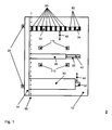
- Fig. 1 shows a top view 2 on a horizontally oriented exemplary mounting device.
- a flat mounting area 12 with a length and a width of some meters each for example, is provided for pivoting around a swiveling axis 99.
- a platform 14 is attached, the height of which corresponds at least to the maximum thickness of a transformer core which my be for example 2 m.
- Four fixtures 110 are fixed to the surface of the flat mounting area by magnetic force, but also different number e.g. six or more is within the idea of the invention. Such fixtures are provided as a helping device for the positioning of the metal sheets on the stack.
- Three beams being adjustable in length 22, 24, 26, 28, 30 are arranged in parallel on the flat mounting area, having a base module 22, 26, 30 (see Fig. 2 ) and a prolongation module 24, 28, 32 each. Also different number of beams, for example five, is possible. There may be more than one prolongation module provided for a base module each inserted into the other. For the second beam 26, 28, the prolongation direction is marked with the arrow 40, the other beams are comparable to this.
- leveling elements 50, 52 are attached to the upper side of the first beam 22, 24 by means of magnetic force, whereas the first leveling elements 50 are attached on the base module of the first beam 22 and the second leveling elements 52, the thickness of which is bigger than that of the first leveling elements 50, are attached on the prolongation module of the first beam 24, what is not exactly shown in this drawing.
- the second beam 26, 28 and the third beam 30, 32 are equipped with leveling elements in the same way, which is not shown in this drawing. All beams 22, 24, 30, 32 except the middle one 26, 28 are movable in the direction, which is marked with the arrows 42 and 44.
- two second skid-like beams 20 are attached, on which the mounting device is supported, if it is in vertical position as shown in Fig. 3 , but also more than two skid-like beams 20 are covered by the idea of this invention.
- Fig. 2 shows a side view on the same horizontal oriented exemplary mounting device.
- the third beam 30, 32 is now shown in total. This beam is located on three supports 34, 36, whereas the base module of the first beam 30 is located on two first supports 34 and the prolongation module of the first beam is located on a second support 36.
- the number of supports may differ from this example. It is also shown, that the first leveling elements 50, which are fixed on the base module 30 of the first beam, are thinner than the second leveling elements 52, which are fixed to the prolongation part 32 of the third beam.
- All leveling elements 50, 52 form a plane basis for stacking a transformer core, respectively a transformer limb 90, as shown in this figure.
- This transformer limb 90 is indicated to be composed of several metals sheets in Fig. 2 .
- the transformer limb 90 is adjacent to the platform 14 on its left side. When the mounting device is turned into its vertical position, as shown in Fig. 3 , the whole weight load of the transformer core respectively of the transformer limb is on the platform 14 then.
- a first skid-like beam 16 is shown, on which the mounting device stands in its horizontal position, whereas of course at least two of them are provided in order to keep it in a stable position.
- Adjacent to the skid-like beam a support bend 18 is shown and adjacent to this a second skid-like beam 20 is shown, too.
- Fig. 3 shows the same exemplary mounting device in its upright position.
- a support beam 38 is attached along at least one first skid-like beam to stabilize the upright position.
- Several fixing device to temporarily fix the transformer core on the flat mounting area are not shown.
Landscapes
- Engineering & Computer Science (AREA)
- Power Engineering (AREA)
- Manufacturing & Machinery (AREA)
- Manufacturing Cores, Coils, And Magnets (AREA)
- Housings And Mounting Of Transformers (AREA)
Abstract
Description
- The invention relates to a mounting device for the manufacturing of transformer cores composed of stacked metal sheets, having a flat mounting area.
- It is known, that cores for electrical transformers are composed of stacked metal sheets to prevent eddy currents during operation of such a transformer. Transformer cores for high power three phase transformers, for example in the range of 10 MVA up to several 100 MVA, have a size of some meters in length and width. Several transformer limbs, preferably 2, 3 or 5, are provided, which normally are arranged in parallel to each other. Those limbs are connected at their ends with yokes.
- Since the weight of such transformer cores is partially more than several 1000 kg, it is advantageous for stacking of such cores to have a certain mounting device, which is adjusted to the shape of the transformer core to be stacked. A high power transformer is no mass product and therefore the setup of such a mounting device has to be adjusted very often.
- Disadvantageously within the state of the art is that the adjustment of the setup of the mounting device to the shape of transformer core to be stacked is very complex and takes several hours.
- Therefore this invention aims at the reduction of the effort for changing the setup of a mounting device for transformer cores.
- This problem is solved by a mounting device for transformer cores with the features described in claim 1.
- Accordingly the mounting device for transformer cores mentioned above is characterized in that the flat mounting area is pivotable around a swiveling axis, that a platform is provided in parallel to the swiveling axis and upright to the flat mounting area, that on the flat mounting area in parallel to it and crosswise to the swiveling axis at least two beams being adjustable in length parallel to each other are arranged, that on that side of the beams which is opposite to the flat mounting area at least two block-shaped leveling elements are provided, which are connected to the beam by magnetic force, that those sides of the at least two block-shaped leveling elements being opposite to the flat mounting area are in line and in parallel to the flat mounting area and that the bock shaped leveling elements being attached to the at least two beams form a basis for the metal sheets to be stacked on them.
- Hence it is possible to easily adapt the basic shape of the basis for stacking the metal sheets. Each limp of the transformer core to be mounted is related to its own beam, which is adjustable in length according to the length of the limb. A beam adjustable in length features at least a base module, which is preferably a hollow beam, and also at least one prolongation module, which is a beam with a smaller cross-section and which is guided moveable inside the hollow base module. By such a telescopic mechanism, the beam becomes adjustable in length.
- Block shaped elements are connected to the upper side of the beams to provide a basis for stacking the metal sheets. This connection is preferably realized by magnetic force. In this case the leveling elements can easily become mounted on and removed from the beam. Since the prolongation module of the beam adjustable in length has a smaller cross-section than the base module, all leveling elements placed on the prolongation module have to be thicker than those which are placed on the base module to provide a plane basis. A distance between the leveling elements is required for example to enable surrounding the completely stacked transformer core with a tape for stabilizing, which is guided between neighbored leveling elements.
- During stacking the metal sheets, the flat mounting area is in horizontal position. This enables an easy stacking. After stacking and unifying the transformer core, the whole mounting area is pivotable into a vertical position to ensure an easier handling and transportation of the transformer core. The transformer core has to be stacked with one side adjacent to the platform, so the weight load of the transformer core goes over on the platform while pivoting.
- In a variant of the invention, the gap between the at least two beams being adjustable in length is also adjustable. This enables an easy adjustment of the stacking base to the shape of the transformer core to be stacked, in particular the distance of the transformer limbs.
- In a certain embodiment of the invention at least two first skid-like beams are connected to the mounting device opposite to the flat mounting area and in parallel to it, being crosswise to the swiveling axis and comprising a support bend at this end which is opposite to the swiveling axis. Preferably a second skid-like beam is connected at the opposite end of each support bend which is in parallel to the platform.
- Hence the mounting device can be as well in horizontal as in vertical position always supported by skid-like beams. Further it is possible to change between those positions in a rolling motion with the support bend.
- In a further variant at least one support beam may be attached to at least one first skid-like beam for stabilizing the position of the mounting device in vertical orientation. Thus it becomes possible to stabilize the mounting device, when it is in vertical position.
- In another version of the invention at least two block-shaped leveling elements may be fixed with at least one permanent magnet each. Those block-shaped leveling elements are preferably made for example of wood. A permanent magnet enables an easy fixing and removing of them and therefore it provides a high flexibility. The material wood enables an easier manual handling due to its little weight.
- In a further embodiment of the invention, at least one actuator is provided for adjusting the length of the at least two beams and/or at least one actuator is provided for the adjustments of the distances between the beams. By using at least one actuator, for example an electrical motor, the adjustment of the mounting device to the requirements of the transformer core to be stacked becomes easier and the handling at all is simplified in an advantageous manner.
- In further variant of the invention at least one mounting fixture is connected with the magnetic force of a permanent magnet on the flat mounting area. Those mounting fixtures are used to match the right position of the metal sheets during stacking. A fixing of those fixtures on the mounting area with a magnetic force will also simplify the handling. Preferably the locations, where to fix those fixtures to the mounting area, are marked for example with color.
- The problem mentioned above is also solved by a method for manufacturing of transformer cores, whereas pre-manufactured metal sheets are stacked into the contour of a transformer core. This method is characterized in that the metal sheets are stacked on a horizontal basis, that the stacked metal sheets are unified to a transformer core, that the transformer core is fixed to the horizontal basis, that the former horizontal basis is pivoted together with the transformer core to a vertical orientation and that the fixed transformer core is released from the basis.
- In this way, i.e. in a horizontal position stacking the metal sheets becomes feasible in a very comfortable and safe way. After unifying the stacked metal sheets to form a transformer core this transformer core will be pivoted into a vertical position, for example by means of a crane, in order to make the further handling of the transformer easier. Such a handling, for example its transportation, can be executed with a crane.
- Further advantageous embodiments of the invention are mentioned in the dependent claims.
- The invention will now be further explained by means of an exemplary embodiment and with reference to the accompanying drawings, in which:
- Figure 1
- shows a top view on a horizontally oriented mounting device,
- Figure 2
- shows a side elevation of a horizontally oriented mounting device and
- Figure 3
- shows a side elevation of a vertically oriented mounting device.
-
Fig. 1 shows atop view 2 on a horizontally oriented exemplary mounting device. Aflat mounting area 12 with a length and a width of some meters each for example, is provided for pivoting around aswiveling axis 99. Upright to theflat mounting area 12 and in parallel to the swiveling axis 99 aplatform 14 is attached, the height of which corresponds at least to the maximum thickness of a transformer core which my be for example 2 m. Fourfixtures 110 are fixed to the surface of the flat mounting area by magnetic force, but also different number e.g. six or more is within the idea of the invention. Such fixtures are provided as a helping device for the positioning of the metal sheets on the stack. - Three beams being adjustable in
length Fig. 2 ), 32 are arranged in parallel on the flat mounting area, having abase module Fig. 2 ) and aprolongation module second beam arrow 40, the other beams are comparable to this. - Furthermore several block-
shaped leveling elements first beam first leveling elements 50 are attached on the base module of thefirst beam 22 and thesecond leveling elements 52, the thickness of which is bigger than that of thefirst leveling elements 50, are attached on the prolongation module of thefirst beam 24, what is not exactly shown in this drawing. Thesecond beam third beam 30, 32 (seeFig. 2 ) are equipped with leveling elements in the same way, which is not shown in this drawing. All beams 22, 24, 30, 32 except themiddle one arrows - On the third beam 30 (s.
Fig. 2 ), 32, atransformer limb 90 is shown, whereas comparable transformer limbs on the other beams and also the transformer yokes are not shown in this drawing. - At the rear side of the
platform 14, two second skid-like beams 20 are attached, on which the mounting device is supported, if it is in vertical position as shown inFig. 3 , but also more than two skid-like beams 20 are covered by the idea of this invention. -
Fig. 2 shows a side view on the same horizontal oriented exemplary mounting device. On theflat mounting area 12 thethird beam supports first beam 30 is located on twofirst supports 34 and the prolongation module of the first beam is located on asecond support 36. - The number of supports may differ from this example. It is also shown, that the
first leveling elements 50, which are fixed on thebase module 30 of the first beam, are thinner than thesecond leveling elements 52, which are fixed to theprolongation part 32 of the third beam. - All leveling
elements transformer limb 90, as shown in this figure. Thistransformer limb 90 is indicated to be composed of several metals sheets inFig. 2 . Thetransformer limb 90 is adjacent to theplatform 14 on its left side. When the mounting device is turned into its vertical position, as shown inFig. 3 , the whole weight load of the transformer core respectively of the transformer limb is on theplatform 14 then. - Opposite to the flat mounting area a first skid-
like beam 16 is shown, on which the mounting device stands in its horizontal position, whereas of course at least two of them are provided in order to keep it in a stable position. Adjacent to the skid-like beam asupport bend 18 is shown and adjacent to this a second skid-like beam 20 is shown, too. - When turning the mounting device into its upright position as shown in
Fig. 3 a rolling motion over thesupport bend 18 has to be done, so that the mounting device stands on the second skid-like beams in its vertical or upright position. -
Fig. 3 shows the same exemplary mounting device in its upright position. Asupport beam 38 is attached along at least one first skid-like beam to stabilize the upright position. Several fixing device to temporarily fix the transformer core on the flat mounting area are not shown. -
- 2
- top view on a horizontal oriented exemplary mounting device
- 4
- side view on a horizontal oriented exemplary mounting device
- 6
- side view on vertical oriented exemplary mounting device
- 12
- mounting area
- 14
- platform
- 16
- first skid-like beam
- 18
- support bend
- 20
- second skid-like beam
- 22
- base module of the first beam
- 24
- prolongation module of the first beam
- 26
- base module of the second beam
- 28
- prolongation module of the second beam
- 30
- base module of the third beam
- 32
- prolongation module of the third beam
- 34
- first support
- 36
- second support
- 38
- support beam
- 40
- prolongation direction
- 42
- move direction of the first beam
- 44
- move direction of the second beam
- 50
- first leveling elements
- 52
- second leveling elements
- 90
- transformer core
- 99
- swiveling axis
- 100
- base
- 110
- mounting fixture
Claims (13)
- A mounting device for manufacturing of transformer cores (90) composed of stacked metal sheets, having a flat mounting area (12),
characterized in that
the flat mounting area (12) is pivotable around a swiveling axis (99), that a platform (14) is provided in parallel to the swiveling axis (99) and upright to the flat mounting area (12), that at least two beams being adjustable in length (22, 24, 26, 28, 30, 32) parallel to each other are arranged on the flat mounting area (12) in parallel to it (12) and crosswise to the swiveling axis (99), that at least two block-shaped leveling elements (50, 52) are provided on that side of the beams which is opposite to the flat mounting area (12), being connected to the beam (22, 24, 26, 28, 30, 32) by magnetic force, that those sides of the at least two block-shaped leveling elements (50, 52) being opposite to the flat mounting area (12) are in line and in parallel to the flat mounting area (12) and that the block shaped leveling elements (50, 52) being attached to the at least two beams (22, 24, 26, 28, 30, 32) form a basis for the metal sheets to be stacked on them. - A mounting device according to claim 1, characterized in that the gap between the at least two beams adjustable in length (22, 24, 26, 28, 30, 32) is also adjustable.
- A mounting device according to claim 1 or claim 2, characterized in that the flat mounting area (12) is pivotable around a swiveling axis (99) at least in-between horizontal and vertical orientation.
- A mounting device according to any of the previous claims, characterized in that at least two first skid-like beams (16) are connected to the mounting device opposite to the flat mounting area (12) and in parallel to it (12), being crosswise to the swiveling axis (99) and comprising a support bend (18) at this end which is opposite to the swiveling axis (99).
- A mounting device according to claim 4, characterized in that at the opposite end of each support bend (18) a second skid-like beam (20) is connected which is in parallel to the platform (14).
- A mounting device according to claim 4 or 5, characterized in that along at least one first skid-like beam (16) at least one support beam (38) is attached for stabilizing the position of the mounting device in vertical orientation.
- A mounting device according to any of the previous claims, characterized in that the at least two block-shaped leveling elements (50, 52) are fixed with at least one permanent magnet each.
- A mounting device according to any of the previous claims characterized in that the at least two block-shaped leveling elements (50, 52) are made of wood.
- A mounting device according to any of the previous claims characterized in that the flat mounting area (12) features at least partial magnetic characteristics.
- A mounting device according to any of the previous claims characterized in that at least one actuator is foreseen for adjusting the length of the at least two beams and/or at least one actuator is foreseen for the adjustments of the distances between the beams (22, 24, 26, 28, 30, 32).
- A mounting device according to any of the previous claims characterized in that at least one mounting fixture (110) is connected with the magnetic force of a permanent magnet on the flat mounting area (12).
- Method for manufacturing of transformer cores, whereas pre-manufactured metal sheets are stacked into the contour of a transformer core (90), characterized in that the metal sheets are stacked on a horizontal basis, that the stacked metal sheets are unified to a transformer core (90), that the transformer core is fixed on the horizontal basis, that the former horizontal basis is pivoted together with the transformer core to a vertical orientation and that the fixed transformer core is released from the plane.
- Usage of a mounting device according to claim 1 or 11 for the manufacturing of a transformer core.
Priority Applications (3)
| Application Number | Priority Date | Filing Date | Title |
|---|---|---|---|
| EP08005409A EP2104119A1 (en) | 2008-03-22 | 2008-03-22 | Mounting device for transformer cores |
| PCT/EP2009/001750 WO2009118099A1 (en) | 2008-03-22 | 2009-03-10 | Mounting device for transformer cores |
| CN2009901001610U CN202145423U (en) | 2008-03-22 | 2009-03-10 | Assembly device for the manufacture of transformer cores consisting of stacked metal sheets |
Applications Claiming Priority (1)
| Application Number | Priority Date | Filing Date | Title |
|---|---|---|---|
| EP08005409A EP2104119A1 (en) | 2008-03-22 | 2008-03-22 | Mounting device for transformer cores |
Publications (1)
| Publication Number | Publication Date |
|---|---|
| EP2104119A1 true EP2104119A1 (en) | 2009-09-23 |
Family
ID=39664500
Family Applications (1)
| Application Number | Title | Priority Date | Filing Date |
|---|---|---|---|
| EP08005409A Withdrawn EP2104119A1 (en) | 2008-03-22 | 2008-03-22 | Mounting device for transformer cores |
Country Status (3)
| Country | Link |
|---|---|
| EP (1) | EP2104119A1 (en) |
| CN (1) | CN202145423U (en) |
| WO (1) | WO2009118099A1 (en) |
Cited By (2)
| Publication number | Priority date | Publication date | Assignee | Title |
|---|---|---|---|---|
| CN103964172A (en) * | 2014-05-21 | 2014-08-06 | 无锡铁新科技有限公司 | Automatic iron core overturning platform |
| CN115985666A (en) * | 2022-12-21 | 2023-04-18 | 无锡普天铁心股份有限公司 | A positioning device for the width and height of iron core windows |
Citations (3)
| Publication number | Priority date | Publication date | Assignee | Title |
|---|---|---|---|---|
| US3685435A (en) | 1969-09-02 | 1972-08-22 | Pshenichny Gennady I | Stand for assembling and pressing magnetic circuits of power transformers |
| US3812567A (en) | 1972-07-07 | 1974-05-28 | I Gryazev | Stand for assembling and pressing magnetic circuits of power transformers |
| DD128398A1 (en) | 1976-11-29 | 1977-11-16 | Horst Schwarze | DEVICE FOR LAYING AND ESTABLISHING A LAMINATED MAGNETIC CORE |
-
2008
- 2008-03-22 EP EP08005409A patent/EP2104119A1/en not_active Withdrawn
-
2009
- 2009-03-10 WO PCT/EP2009/001750 patent/WO2009118099A1/en not_active Ceased
- 2009-03-10 CN CN2009901001610U patent/CN202145423U/en not_active Expired - Lifetime
Patent Citations (3)
| Publication number | Priority date | Publication date | Assignee | Title |
|---|---|---|---|---|
| US3685435A (en) | 1969-09-02 | 1972-08-22 | Pshenichny Gennady I | Stand for assembling and pressing magnetic circuits of power transformers |
| US3812567A (en) | 1972-07-07 | 1974-05-28 | I Gryazev | Stand for assembling and pressing magnetic circuits of power transformers |
| DD128398A1 (en) | 1976-11-29 | 1977-11-16 | Horst Schwarze | DEVICE FOR LAYING AND ESTABLISHING A LAMINATED MAGNETIC CORE |
Cited By (3)
| Publication number | Priority date | Publication date | Assignee | Title |
|---|---|---|---|---|
| CN103964172A (en) * | 2014-05-21 | 2014-08-06 | 无锡铁新科技有限公司 | Automatic iron core overturning platform |
| CN103964172B (en) * | 2014-05-21 | 2016-06-08 | 无锡普天铁心股份有限公司 | Automatic reversible table unshakable in one's determination |
| CN115985666A (en) * | 2022-12-21 | 2023-04-18 | 无锡普天铁心股份有限公司 | A positioning device for the width and height of iron core windows |
Also Published As
| Publication number | Publication date |
|---|---|
| CN202145423U (en) | 2012-02-15 |
| WO2009118099A1 (en) | 2009-10-01 |
Similar Documents
| Publication | Publication Date | Title |
|---|---|---|
| CA2781203C (en) | Electrical transformer assembly | |
| CN102385973A (en) | Wound transformer core with support structure | |
| JP6901788B2 (en) | Three-phase transformer | |
| ES2544850T3 (en) | Method for manufacturing a stacked triangular core transformer | |
| KR20180125989A (en) | Rotational ball-guided voice coil motor | |
| KR20110098734A (en) | Gravity Compensation for Optical Elements in Projection Exposure Equipment | |
| US20180040409A1 (en) | Transformer | |
| EP2104119A1 (en) | Mounting device for transformer cores | |
| US9580270B2 (en) | Winding fixing device | |
| JP6198978B2 (en) | Transformer | |
| EP2395521B1 (en) | Method for manufacture of triangular transformer cores made of amorphous metal | |
| KR20130029761A (en) | Method and device for assembling a transformer | |
| EP1895830A1 (en) | A displacement device as well as a component placement device | |
| EP2618347B1 (en) | Transformer-core | |
| EP3369161B1 (en) | Machine for shaping rectangular wire coil heads and method therefor | |
| WO2014066075A1 (en) | Transformer having an interlocking core frame | |
| EP1081722A3 (en) | Electromagnetic actuator, its manufacturing method, and optical scanner using the same electromagnetic actuator | |
| EP2618346B1 (en) | Transformer-core | |
| US8919839B2 (en) | Electromagnetic lifter for moving horizontal-axis coils and the like | |
| CN105337428B (en) | A kind of portable radio energy transmission system multiple degrees of freedom test fixture and its application method | |
| DE102013208768A1 (en) | Electromagnetic actuator, actuatable movable system containing a plurality of such actuators and actuator movement method | |
| KR20230153263A (en) | Stage apparatus, transfer apparatus and article manufacturing method | |
| US12215594B2 (en) | Support member and support system for installing a turbine assembly | |
| CN214689663U (en) | Feeding device for machining winding wire body for motor | |
| CN102290203A (en) | Transformer |
Legal Events
| Date | Code | Title | Description |
|---|---|---|---|
| PUAI | Public reference made under article 153(3) epc to a published international application that has entered the european phase |
Free format text: ORIGINAL CODE: 0009012 |
|
| AK | Designated contracting states |
Kind code of ref document: A1 Designated state(s): AT BE BG CH CY CZ DE DK EE ES FI FR GB GR HR HU IE IS IT LI LT LU LV MC MT NL NO PL PT RO SE SI SK TR |
|
| AX | Request for extension of the european patent |
Extension state: AL BA MK RS |
|
| 17P | Request for examination filed |
Effective date: 20091006 |
|
| 17Q | First examination report despatched |
Effective date: 20100125 |
|
| AKX | Designation fees paid |
Designated state(s): AT BE BG CH CY CZ DE DK EE ES FI FR GB GR HR HU IE IS IT LI LT LU LV MC MT NL NO PL PT RO SE SI SK TR |
|
| STAA | Information on the status of an ep patent application or granted ep patent |
Free format text: STATUS: THE APPLICATION IS DEEMED TO BE WITHDRAWN |
|
| 18D | Application deemed to be withdrawn |
Effective date: 20121002 |