EP2103869A1 - Light-emitting diode lighting system - Google Patents
Light-emitting diode lighting system Download PDFInfo
- Publication number
- EP2103869A1 EP2103869A1 EP09003522A EP09003522A EP2103869A1 EP 2103869 A1 EP2103869 A1 EP 2103869A1 EP 09003522 A EP09003522 A EP 09003522A EP 09003522 A EP09003522 A EP 09003522A EP 2103869 A1 EP2103869 A1 EP 2103869A1
- Authority
- EP
- European Patent Office
- Prior art keywords
- facets
- lighting system
- light
- reflector
- light rays
- Prior art date
- Legal status (The legal status is an assumption and is not a legal conclusion. Google has not performed a legal analysis and makes no representation as to the accuracy of the status listed.)
- Granted
Links
- 230000005540 biological transmission Effects 0.000 claims description 6
- 230000004438 eyesight Effects 0.000 description 2
- 238000005286 illumination Methods 0.000 description 2
- 238000009792 diffusion process Methods 0.000 description 1
- 230000004313 glare Effects 0.000 description 1
- 238000001465 metallisation Methods 0.000 description 1
Images
Classifications
-
- F—MECHANICAL ENGINEERING; LIGHTING; HEATING; WEAPONS; BLASTING
- F21—LIGHTING
- F21V—FUNCTIONAL FEATURES OR DETAILS OF LIGHTING DEVICES OR SYSTEMS THEREOF; STRUCTURAL COMBINATIONS OF LIGHTING DEVICES WITH OTHER ARTICLES, NOT OTHERWISE PROVIDED FOR
- F21V7/00—Reflectors for light sources
- F21V7/0008—Reflectors for light sources providing for indirect lighting
-
- F—MECHANICAL ENGINEERING; LIGHTING; HEATING; WEAPONS; BLASTING
- F21—LIGHTING
- F21V—FUNCTIONAL FEATURES OR DETAILS OF LIGHTING DEVICES OR SYSTEMS THEREOF; STRUCTURAL COMBINATIONS OF LIGHTING DEVICES WITH OTHER ARTICLES, NOT OTHERWISE PROVIDED FOR
- F21V7/00—Reflectors for light sources
- F21V7/04—Optical design
- F21V7/048—Optical design with facets structure
-
- F—MECHANICAL ENGINEERING; LIGHTING; HEATING; WEAPONS; BLASTING
- F21—LIGHTING
- F21V—FUNCTIONAL FEATURES OR DETAILS OF LIGHTING DEVICES OR SYSTEMS THEREOF; STRUCTURAL COMBINATIONS OF LIGHTING DEVICES WITH OTHER ARTICLES, NOT OTHERWISE PROVIDED FOR
- F21V7/00—Reflectors for light sources
- F21V7/04—Optical design
- F21V7/09—Optical design with a combination of different curvatures
-
- F—MECHANICAL ENGINEERING; LIGHTING; HEATING; WEAPONS; BLASTING
- F21—LIGHTING
- F21S—NON-PORTABLE LIGHTING DEVICES; SYSTEMS THEREOF; VEHICLE LIGHTING DEVICES SPECIALLY ADAPTED FOR VEHICLE EXTERIORS
- F21S43/00—Signalling devices specially adapted for vehicle exteriors, e.g. brake lamps, direction indicator lights or reversing lights
- F21S43/30—Signalling devices specially adapted for vehicle exteriors, e.g. brake lamps, direction indicator lights or reversing lights characterised by reflectors
-
- F—MECHANICAL ENGINEERING; LIGHTING; HEATING; WEAPONS; BLASTING
- F21—LIGHTING
- F21Y—INDEXING SCHEME ASSOCIATED WITH SUBCLASSES F21K, F21L, F21S and F21V, RELATING TO THE FORM OR THE KIND OF THE LIGHT SOURCES OR OF THE COLOUR OF THE LIGHT EMITTED
- F21Y2115/00—Light-generating elements of semiconductor light sources
- F21Y2115/10—Light-emitting diodes [LED]
Definitions
- the present invention relates to a light emitting diode lighting system.
- a lighting system comprising a light-emitting diode (LED) emitting light rays in at least one transmission direction, in a first direction, and a reflector adapted to redirect the light rays in an output direction.
- LED light-emitting diode
- the document US 2005/0083699 describes a lighting system of the type described above, wherein the reflector comprises a first reflector consisting of a reflecting mirror and a second reflector for returning the light received from the first reflector in all directions.
- the lighting system described in this document initially makes it possible to send the light in a direction opposite to the direction of emission of the LED and then to return the light in a direction substantially perpendicular to the direction of emission thanks to a second reflector .
- the latter has a substantially conical shape.
- the system described in this document is cumbersome and can not be used in small spaces, for example for vehicle brake lights.
- the system does not make it possible to direct the final light beam in a direction opposite to the initial beam.
- the present invention aims to overcome these disadvantages.
- the present invention proposes a lighting system of the type described above, in which the reflector comprises at least one mirror and one deflection facet, the mirror being adapted to direct the light rays emitted by the LED towards at least one facet of return which is adapted to redirect the light rays in the direction of exit, parallel to the direction of emission, in a second direction opposite to the first direction.
- the system makes it possible to obtain a homogeneous light without direct vision of the LED.
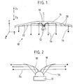
- the figure 1 represents the lighting system 10 according to the invention.
- the system 10 comprises a light emitting diode 12, hereinafter called LED, which emits a set of light rays 14 in a transmission direction Z, in a first direction Z1.
- the system further comprises a reflector 16 of glossy polished plastic material having a reflective treatment of metallization type, adapted to reflect light.
- a reflector 16 of glossy polished plastic material having a reflective treatment of metallization type, adapted to reflect light.
- the reflector 16 has two parts.
- a first part consists of a mirror 18 which directly receives the light rays 14 emitted by the LED 12 and which sends them in a determined direction to a second part of the reflector.
- the mirror 18 is adapted to return the light rays 14 in the direction perpendicular x to the direction of emission Z. However, it can be expected to redirect the light rays 14 in other directions, depending on the position of the second part reflector.
- the second part of the reflector comprises at least one deflection facet 20 adapted to direct the light rays 14, arriving on the facet 20, in a direction parallel to the transmission direction Z, but in an opposite direction Z2.
- the light rays 14 coming out of the lighting system 10 are directed in a direction opposite to the rays emitted by the LED 12.
- the second part of the reflector further comprises a series of deflection facets 20 alternating with side facets 22.
- the side facets 22 extend in a plane so that the light rays 14 directed by the mirror 18 do not
- These lateral facets 22 extend in a plane inclined with respect to the direction of the light rays redirected by the mirror 18, so that the distal ends of the lateral facets 22 can be directed onto said lateral facets 22. , in relation to the mirror, move away from the light rays 14.
- the return facets 20 are mirror surfaces that direct the rays on a given target.
- the dimensions of each deflection facet 20 are determined so that each of them returns the same amount of light, in order to obtain an illumination homogeneity.
- the final illumination obtained consists of a set of light beams spaced at a constant pitch depending on the total length of the reflector, each beam corresponding to a quantity of light reflected by the return facet.
- the pitch between each deflection facet (20) corresponds to the length of a side facet (22) and is determined according to the length of the reflector to be obtained.
- each return facet (20) is variable and determined so that each of them returns the same amount of light.
- the height is calculated according to the number of deflection facets (20) desired so the step between each facet.
- the return facets (20) can take different forms depending on the target to be illuminated.
- the shape of these return facets can be flat or complex such as concave or convex combined or not with a circular or polygon shape.
- the shape of the return facet is determined according to the shape of the desired final beam.
- the final beam extends along the transmission direction Z in the direction Z2.
- the diffusion of the final beam may be in the form of a conical beam around the emission direction Z, or a beam which has a constant section of the same dimension as the surface of the return facet.
- the reflector as shown on the figure 1 comprises two mirrors (18), and two sets of alternating facets (20) and side facets (22).
- the two mirrors (18) as well as the two series are symmetrical with respect to a central axis C substantially parallel to the emission direction Z.
- the reflector is made in one piece, and is arranged so that the central axis is substantially coincident with the emission direction Z.
- the present invention finds particular application in vehicle lights. Indeed its compact dimensions allow to have the system in relatively small spaces. In addition this system allows a non-direct vision of the LED, to avoid any glare of the following vehicles by the LED light.
Abstract
Description
La présente invention se rapporte à un système d'éclairage à diode électroluminescente.The present invention relates to a light emitting diode lighting system.
Plus particulièrement elle concerne un système d'éclairage comportant une diode électroluminescente (LED) émettant des rayons lumineux selon au moins une direction d'émission, dans un premier sens, et un réflecteur adapté à rediriger les rayons lumineux selon une direction de sortie.More particularly, it relates to a lighting system comprising a light-emitting diode (LED) emitting light rays in at least one transmission direction, in a first direction, and a reflector adapted to redirect the light rays in an output direction.
Le document
Toutefois le système décrit dans ce document est encombrant et ne peut pas être utilisé dans des espaces réduits, par exemple pour des feux stop de véhicule. De plus le système ne permet pas de diriger le faisceau de lumière final selon une direction opposée au faisceau initial.However, the system described in this document is cumbersome and can not be used in small spaces, for example for vehicle brake lights. In addition, the system does not make it possible to direct the final light beam in a direction opposite to the initial beam.
La présente invention a pour but de remédier à ces inconvénients.The present invention aims to overcome these disadvantages.
A cet effet la présente invention propose un système d'éclairage du type décrit précédemment, dans lequel le réflecteur comporte au moins un miroir et une facette de renvoi, le miroir étant adapté à diriger les rayons lumineux émis par la LED vers au moins une facette de renvoi qui est adaptée à rediriger les rayons lumineux selon la direction de sortie, parallèlement à la direction d'émission, dans un deuxième sens opposé au premier sens.For this purpose, the present invention proposes a lighting system of the type described above, in which the reflector comprises at least one mirror and one deflection facet, the mirror being adapted to direct the light rays emitted by the LED towards at least one facet of return which is adapted to redirect the light rays in the direction of exit, parallel to the direction of emission, in a second direction opposite to the first direction.
Grâce à ces dispositions, le système permet d'obtenir une lumière homogène sans vision directe de la LED.Thanks to these arrangements, the system makes it possible to obtain a homogeneous light without direct vision of the LED.
Selon d'autres caractéristiques:
- le réflecteur comporte une série de facettes de renvoi en alternance avec des facettes latérales;
- le miroir est disposé adjacent à une facette latérale;
- le réflecteur comporte deux miroirs et deux séries de facettes de renvois en alternance avec des parties latérales, les deux miroirs et les deux séries étant disposés symétriques par rapport à un axe central sensiblement parallèle à la direction d'émission;
- les deux miroirs sont disposés adjacents;
- the reflector has a series of return facets alternating with lateral facets;
- the mirror is disposed adjacent to a side facet;
- the reflector comprises two mirrors and two sets of alternating facets of references with lateral parts, the two mirrors and the two series being arranged symmetrically with respect to a central axis substantially parallel to the emission direction;
- the two mirrors are arranged adjacent;
D'autres caractéristiques et avantages de l'invention apparaîtront au cours de la description suivante des modes de réalisation, donnés à titre d'exemple non limitatif, en regard des dessins joints et dans lesquels :
- la
figure 1 représente une vue d'ensemble du système d'éclairage selon l'invention, - la
figure 2 représente une vue de détail de la LED et du miroir dans le système d'éclairage selon l'invention.
- the
figure 1 represents an overview of the lighting system according to the invention, - the
figure 2 represents a detailed view of the LED and the mirror in the lighting system according to the invention.
Sur les différentes figures, les mêmes références désignent des éléments identiques ou similaires.In the different figures, the same references designate identical or similar elements.
La
Le système comporte en outre un réflecteur 16 en matière plastique polie glacée disposant d'un traitement réfléchissant de type métallisation, adapté à réfléchir la lumière. Ainsi la lumière émise par la LED 12 ne pénètre pas dans le réflecteur 16 et est complètement réfléchie par ce dernier.The system further comprises a
Le réflecteur 16 comporte deux parties. Une première partie est constituée d'un miroir 18 qui reçoit directement les rayons lumineux 14 émis par la LED 12 et qui les renvoie selon une direction déterminée, vers une deuxième partie du réflecteur. Tel que représenté à la
La deuxième partie du réflecteur comporte au moins une facette de renvoi 20 adaptée à diriger les rayons lumineux 14, arrivant sur la facette 20, selon une direction parallèle à la direction d'émission Z, mais dans un sens opposé Z2. Ainsi les rayons de lumière 14 sortant du système d'éclairage 10 sont dirigés selon un sens opposé aux rayons émis par la LED 12.The second part of the reflector comprises at least one
Tel que représenté sur la
Les facettes de renvoi 20 sont des surfaces miroir qui permettent de diriger les rayons sur une cible donnée. Les dimensions de chaque facette de renvoi 20 sont déterminées pour que chacune d'elle renvoie la même quantité de lumière, afin d'obtenir une homogénéité d'éclairage. L'éclairage final obtenu est constitué d'un ensemble de faisceaux lumineux espacés d'un pas constant dépendant de la longueur totale du réflecteur, chaque faisceau correspondant à une quantité de lumière renvoyée par la facette de renvoi.The
Le pas entre chaque facette de renvoi (20) correspond à la longueur d'une facette latérale (22) et est déterminé en fonction de la longueur du réflecteur à obtenir.The pitch between each deflection facet (20) corresponds to the length of a side facet (22) and is determined according to the length of the reflector to be obtained.
La hauteur de chaque facette de renvoi (20) est variable et déterminée pour que chacune d'elle renvoie la même quantité de lumière. La hauteur est calculée en fonction du nombre de facettes de renvoi (20) désiré donc du pas entre chaque facette.The height of each return facet (20) is variable and determined so that each of them returns the same amount of light. The height is calculated according to the number of deflection facets (20) desired so the step between each facet.
Selon une vue de dessous, les facettes de renvoi (20) peuvent prendre différentes formes en fonction de la cible à éclairer. La forme de ces facettes de renvoi peut être plane ou complexe telle que concave ou convexe combinée ou non à une forme circulaire ou de polygone. La forme de la facette de renvoi est déterminée en fonction de la forme du faisceau final souhaité. Le faisceau final s'étend le long de la direction d'émission Z dans le sens Z2. Par exemple la diffusion du faisceau final peut se présenter sous la forme d'un faisceau conique autour de la direction d'émission Z, ou bien un faisceau qui présente une section constante de même dimension que la surface de la facette de renvoi.According to a view from below, the return facets (20) can take different forms depending on the target to be illuminated. The shape of these return facets can be flat or complex such as concave or convex combined or not with a circular or polygon shape. The shape of the return facet is determined according to the shape of the desired final beam. The final beam extends along the transmission direction Z in the direction Z2. For example, the diffusion of the final beam may be in the form of a conical beam around the emission direction Z, or a beam which has a constant section of the same dimension as the surface of the return facet.
Le réflecteur, tel que représenté sur la
Le réflecteur est réalisé en une seule pièce, et il est disposé de manière à ce que l'axe central soit sensiblement confondu avec la direction d'émission Z.The reflector is made in one piece, and is arranged so that the central axis is substantially coincident with the emission direction Z.
La présente invention trouve une application particulière dans les feux de véhicule. En effet ses dimensions compactes permettent de disposer le système dans des espaces relativement réduits. De plus ce système permet une vision non directe de la LED, pour éviter tout éblouissement des véhicules suivants par la lumière de la LED.The present invention finds particular application in vehicle lights. Indeed its compact dimensions allow to have the system in relatively small spaces. In addition this system allows a non-direct vision of the LED, to avoid any glare of the following vehicles by the LED light.
Claims (6)
Applications Claiming Priority (1)
| Application Number | Priority Date | Filing Date | Title |
|---|---|---|---|
| FR0801492A FR2928992B1 (en) | 2008-03-19 | 2008-03-19 | ELECTROLUMINESCENT DIODE LIGHTING SYSTEM. |
Publications (2)
| Publication Number | Publication Date |
|---|---|
| EP2103869A1 true EP2103869A1 (en) | 2009-09-23 |
| EP2103869B1 EP2103869B1 (en) | 2014-05-14 |
Family
ID=39473983
Family Applications (1)
| Application Number | Title | Priority Date | Filing Date |
|---|---|---|---|
| EP09003522.1A Not-in-force EP2103869B1 (en) | 2008-03-19 | 2009-03-11 | Light-emitting diode lighting system |
Country Status (2)
| Country | Link |
|---|---|
| EP (1) | EP2103869B1 (en) |
| FR (1) | FR2928992B1 (en) |
Cited By (2)
| Publication number | Priority date | Publication date | Assignee | Title |
|---|---|---|---|---|
| WO2013182966A1 (en) * | 2012-06-04 | 2013-12-12 | Koninklijke Philips N.V. | Lighting device with optical reflector, luminaire having such lighting device and method of manufacturing a compact optical reflector |
| CN104662363A (en) * | 2012-06-04 | 2015-05-27 | 皇家飞利浦有限公司 | Lighting device with optical reflector, luminaire having such lighting device and method of manufacturing a compact optical reflector |
Citations (7)
| Publication number | Priority date | Publication date | Assignee | Title |
|---|---|---|---|---|
| US6527420B1 (en) * | 2001-12-06 | 2003-03-04 | Prokia Technology Co., Ltd. | Illuminating module for a display apparatus |
| EP1300626A2 (en) * | 2001-10-05 | 2003-04-09 | Schefenacker Vision Systems Germany GmbH & Co. KG | Reflector for a lamp, such as a tail lamp, a headlamp or a inner lamp of a motor vehicle |
| WO2003078203A1 (en) * | 2002-03-14 | 2003-09-25 | Schefenacker Vision Systems Germany Gmbh & Co. Kg | Luminous unit, particularly as an additional light in sideview mirrors of motor vehicles |
| WO2004097293A1 (en) * | 2003-04-30 | 2004-11-11 | Lighting Innovation Center Ag | Carrier for light and light head provided with a carrier and reflector |
| US20050083699A1 (en) | 2003-08-12 | 2005-04-21 | Greg Rhoads | Apparatus and method for using emitting diodes (LED) in a side-emitting device |
| WO2007022314A2 (en) * | 2005-08-17 | 2007-02-22 | Illumination Management Solutions, Inc. | An improved optic for leds and other light sources |
| US20070217193A1 (en) * | 2006-03-17 | 2007-09-20 | Industrial Technology Research Institute | Reflective illumination device |
-
2008
- 2008-03-19 FR FR0801492A patent/FR2928992B1/en not_active Expired - Fee Related
-
2009
- 2009-03-11 EP EP09003522.1A patent/EP2103869B1/en not_active Not-in-force
Patent Citations (7)
| Publication number | Priority date | Publication date | Assignee | Title |
|---|---|---|---|---|
| EP1300626A2 (en) * | 2001-10-05 | 2003-04-09 | Schefenacker Vision Systems Germany GmbH & Co. KG | Reflector for a lamp, such as a tail lamp, a headlamp or a inner lamp of a motor vehicle |
| US6527420B1 (en) * | 2001-12-06 | 2003-03-04 | Prokia Technology Co., Ltd. | Illuminating module for a display apparatus |
| WO2003078203A1 (en) * | 2002-03-14 | 2003-09-25 | Schefenacker Vision Systems Germany Gmbh & Co. Kg | Luminous unit, particularly as an additional light in sideview mirrors of motor vehicles |
| WO2004097293A1 (en) * | 2003-04-30 | 2004-11-11 | Lighting Innovation Center Ag | Carrier for light and light head provided with a carrier and reflector |
| US20050083699A1 (en) | 2003-08-12 | 2005-04-21 | Greg Rhoads | Apparatus and method for using emitting diodes (LED) in a side-emitting device |
| WO2007022314A2 (en) * | 2005-08-17 | 2007-02-22 | Illumination Management Solutions, Inc. | An improved optic for leds and other light sources |
| US20070217193A1 (en) * | 2006-03-17 | 2007-09-20 | Industrial Technology Research Institute | Reflective illumination device |
Cited By (4)
| Publication number | Priority date | Publication date | Assignee | Title |
|---|---|---|---|---|
| WO2013182966A1 (en) * | 2012-06-04 | 2013-12-12 | Koninklijke Philips N.V. | Lighting device with optical reflector, luminaire having such lighting device and method of manufacturing a compact optical reflector |
| CN104662363A (en) * | 2012-06-04 | 2015-05-27 | 皇家飞利浦有限公司 | Lighting device with optical reflector, luminaire having such lighting device and method of manufacturing a compact optical reflector |
| CN104662363B (en) * | 2012-06-04 | 2017-05-17 | 飞利浦照明控股有限公司 | Lighting device with optical reflector, luminaire having such lighting device and method of manufacturing a compact optical reflector |
| US9989213B2 (en) | 2012-06-04 | 2018-06-05 | Philips Lighting Holding B.V. | Lighting device with optical reflector, luminaire having such lighting device and method of manufacturing a compact optical reflector |
Also Published As
| Publication number | Publication date |
|---|---|
| FR2928992A1 (en) | 2009-09-25 |
| FR2928992B1 (en) | 2010-05-14 |
| EP2103869B1 (en) | 2014-05-14 |
Similar Documents
| Publication | Publication Date | Title |
|---|---|---|
| EP2901075B1 (en) | Light guide for a motor vehicle lighting and/or signalling device | |
| EP1746339B1 (en) | Device for lighting or signalising, in particular for vehicles | |
| EP1288562B1 (en) | Lighting or signalling device for motor vehicle | |
| EP2541128B1 (en) | Optical device and signalling and / or lighting system | |
| FR2852379A1 (en) | Vehicle lamp, has coupling unit with optical waveguide units that are formed with ellipsoidal surface with two focuses and coupled in series by coupling part | |
| FR2901345A1 (en) | LIGHTING AND / OR SIGNALING DEVICE FOR A MOTOR VEHICLE. | |
| EP1443265A1 (en) | Light guide provided with reflectors | |
| FR2973476A1 (en) | OPTICAL SYSTEM FOR GENERATING A COMPOSITE LARGE BEAM OF LARGE ANGULAR OPENING | |
| FR2844033A1 (en) | Motor vehicle headlamp with predetermined light distribution diagram, uses lamp units containing one or more light-emitting diodes with some units providing direct lighting, some controlled-direction lighting and others diffuse lighting | |
| FR2860280A1 (en) | VEHICLE HEADLIGHT WITH PHOTOEMISSIVE ELEMENT LAMPS | |
| FR3030684B1 (en) | LUMINOUS DEVICE COMPRISING SURFACE SOURCES OF LIGHT | |
| FR2904680A1 (en) | VEHICLE FIRE | |
| FR2886237A1 (en) | IMPROVED APPEARANCE LIGHTING OR SIGNALING DEVICE FOR MOTOR VEHICLE | |
| FR2890917A1 (en) | Signaling light for vehicle e.g. automobile, has light guides installed with respect to light sources so that part of emitted light arrive in guides, where remaining part of light is emitted outwards without passing through guides | |
| FR2863038A1 (en) | VEHICLE HEADLIGHT HAVING THREE REFLECTORS | |
| FR2929682A1 (en) | LIGHTING DEVICE FOR A MOTOR VEHICLE | |
| EP1739468B1 (en) | Lighting or signalling device for an automobile | |
| EP2738448A2 (en) | Illuminating and/or signalling device, more particularly for automobile vehicle | |
| EP3521692B1 (en) | Dual-function light module with common lit surface | |
| EP2103869B1 (en) | Light-emitting diode lighting system | |
| FR3009060A1 (en) | LIGHTING SYSTEM COMPRISING A WHITE LIGHT AND A LIGHT OF ANOTHER COLOR | |
| EP2803903A1 (en) | Lighting and/or signalling device, in particular for a motor vehicle | |
| EP2711610A1 (en) | Lighting and/or signalling device, in particular for a motor vehicle | |
| EP1488954A1 (en) | Lighting or signaling system for automotive vehicle | |
| EP2650600A1 (en) | Lightguide for a light-emitting device of a motor vehicle |
Legal Events
| Date | Code | Title | Description |
|---|---|---|---|
| PUAI | Public reference made under article 153(3) epc to a published international application that has entered the european phase |
Free format text: ORIGINAL CODE: 0009012 |
|
| AK | Designated contracting states |
Kind code of ref document: A1 Designated state(s): AT BE BG CH CY CZ DE DK EE ES FI FR GB GR HR HU IE IS IT LI LT LU LV MC MK MT NL NO PL PT RO SE SI SK TR |
|
| AX | Request for extension of the european patent |
Extension state: AL BA RS |
|
| 17P | Request for examination filed |
Effective date: 20100323 |
|
| AKX | Designation fees paid |
Designated state(s): AT BE BG CH CY CZ DE DK EE ES FI FR GB GR HR HU IE IS IT LI LT LU LV MC MK MT NL NO PL PT RO SE SI SK TR |
|
| 17Q | First examination report despatched |
Effective date: 20100503 |
|
| GRAP | Despatch of communication of intention to grant a patent |
Free format text: ORIGINAL CODE: EPIDOSNIGR1 |
|
| INTG | Intention to grant announced |
Effective date: 20140127 |
|
| GRAS | Grant fee paid |
Free format text: ORIGINAL CODE: EPIDOSNIGR3 |
|
| GRAA | (expected) grant |
Free format text: ORIGINAL CODE: 0009210 |
|
| AK | Designated contracting states |
Kind code of ref document: B1 Designated state(s): AT BE BG CH CY CZ DE DK EE ES FI FR GB GR HR HU IE IS IT LI LT LU LV MC MK MT NL NO PL PT RO SE SI SK TR |
|
| REG | Reference to a national code |
Ref country code: GB Ref legal event code: FG4D Free format text: NOT ENGLISH |
|
| REG | Reference to a national code |
Ref country code: AT Ref legal event code: REF Ref document number: 668572 Country of ref document: AT Kind code of ref document: T Effective date: 20140615 |
|
| REG | Reference to a national code |
Ref country code: IE Ref legal event code: FG4D Free format text: LANGUAGE OF EP DOCUMENT: FRENCH |
|
| REG | Reference to a national code |
Ref country code: DE Ref legal event code: R096 Ref document number: 602009024043 Country of ref document: DE Effective date: 20140626 |
|
| REG | Reference to a national code |
Ref country code: NL Ref legal event code: VDEP Effective date: 20140514 Ref country code: AT Ref legal event code: MK05 Ref document number: 668572 Country of ref document: AT Kind code of ref document: T Effective date: 20140514 |
|
| REG | Reference to a national code |
Ref country code: LT Ref legal event code: MG4D |
|
| PG25 | Lapsed in a contracting state [announced via postgrant information from national office to epo] |
Ref country code: FI Free format text: LAPSE BECAUSE OF FAILURE TO SUBMIT A TRANSLATION OF THE DESCRIPTION OR TO PAY THE FEE WITHIN THE PRESCRIBED TIME-LIMIT Effective date: 20140514 Ref country code: IS Free format text: LAPSE BECAUSE OF FAILURE TO SUBMIT A TRANSLATION OF THE DESCRIPTION OR TO PAY THE FEE WITHIN THE PRESCRIBED TIME-LIMIT Effective date: 20140914 Ref country code: CY Free format text: LAPSE BECAUSE OF FAILURE TO SUBMIT A TRANSLATION OF THE DESCRIPTION OR TO PAY THE FEE WITHIN THE PRESCRIBED TIME-LIMIT Effective date: 20140514 Ref country code: LT Free format text: LAPSE BECAUSE OF FAILURE TO SUBMIT A TRANSLATION OF THE DESCRIPTION OR TO PAY THE FEE WITHIN THE PRESCRIBED TIME-LIMIT Effective date: 20140514 Ref country code: GR Free format text: LAPSE BECAUSE OF FAILURE TO SUBMIT A TRANSLATION OF THE DESCRIPTION OR TO PAY THE FEE WITHIN THE PRESCRIBED TIME-LIMIT Effective date: 20140815 Ref country code: NO Free format text: LAPSE BECAUSE OF FAILURE TO SUBMIT A TRANSLATION OF THE DESCRIPTION OR TO PAY THE FEE WITHIN THE PRESCRIBED TIME-LIMIT Effective date: 20140814 |
|
| PG25 | Lapsed in a contracting state [announced via postgrant information from national office to epo] |
Ref country code: PL Free format text: LAPSE BECAUSE OF FAILURE TO SUBMIT A TRANSLATION OF THE DESCRIPTION OR TO PAY THE FEE WITHIN THE PRESCRIBED TIME-LIMIT Effective date: 20140514 Ref country code: AT Free format text: LAPSE BECAUSE OF FAILURE TO SUBMIT A TRANSLATION OF THE DESCRIPTION OR TO PAY THE FEE WITHIN THE PRESCRIBED TIME-LIMIT Effective date: 20140514 Ref country code: HR Free format text: LAPSE BECAUSE OF FAILURE TO SUBMIT A TRANSLATION OF THE DESCRIPTION OR TO PAY THE FEE WITHIN THE PRESCRIBED TIME-LIMIT Effective date: 20140514 Ref country code: LV Free format text: LAPSE BECAUSE OF FAILURE TO SUBMIT A TRANSLATION OF THE DESCRIPTION OR TO PAY THE FEE WITHIN THE PRESCRIBED TIME-LIMIT Effective date: 20140514 Ref country code: SE Free format text: LAPSE BECAUSE OF FAILURE TO SUBMIT A TRANSLATION OF THE DESCRIPTION OR TO PAY THE FEE WITHIN THE PRESCRIBED TIME-LIMIT Effective date: 20140514 Ref country code: ES Free format text: LAPSE BECAUSE OF FAILURE TO SUBMIT A TRANSLATION OF THE DESCRIPTION OR TO PAY THE FEE WITHIN THE PRESCRIBED TIME-LIMIT Effective date: 20140514 |
|
| PG25 | Lapsed in a contracting state [announced via postgrant information from national office to epo] |
Ref country code: PT Free format text: LAPSE BECAUSE OF FAILURE TO SUBMIT A TRANSLATION OF THE DESCRIPTION OR TO PAY THE FEE WITHIN THE PRESCRIBED TIME-LIMIT Effective date: 20140915 |
|
| PG25 | Lapsed in a contracting state [announced via postgrant information from national office to epo] |
Ref country code: DK Free format text: LAPSE BECAUSE OF FAILURE TO SUBMIT A TRANSLATION OF THE DESCRIPTION OR TO PAY THE FEE WITHIN THE PRESCRIBED TIME-LIMIT Effective date: 20140514 Ref country code: CZ Free format text: LAPSE BECAUSE OF FAILURE TO SUBMIT A TRANSLATION OF THE DESCRIPTION OR TO PAY THE FEE WITHIN THE PRESCRIBED TIME-LIMIT Effective date: 20140514 Ref country code: SK Free format text: LAPSE BECAUSE OF FAILURE TO SUBMIT A TRANSLATION OF THE DESCRIPTION OR TO PAY THE FEE WITHIN THE PRESCRIBED TIME-LIMIT Effective date: 20140514 Ref country code: RO Free format text: LAPSE BECAUSE OF FAILURE TO SUBMIT A TRANSLATION OF THE DESCRIPTION OR TO PAY THE FEE WITHIN THE PRESCRIBED TIME-LIMIT Effective date: 20140514 Ref country code: EE Free format text: LAPSE BECAUSE OF FAILURE TO SUBMIT A TRANSLATION OF THE DESCRIPTION OR TO PAY THE FEE WITHIN THE PRESCRIBED TIME-LIMIT Effective date: 20140514 |
|
| REG | Reference to a national code |
Ref country code: DE Ref legal event code: R097 Ref document number: 602009024043 Country of ref document: DE |
|
| PG25 | Lapsed in a contracting state [announced via postgrant information from national office to epo] |
Ref country code: NL Free format text: LAPSE BECAUSE OF FAILURE TO SUBMIT A TRANSLATION OF THE DESCRIPTION OR TO PAY THE FEE WITHIN THE PRESCRIBED TIME-LIMIT Effective date: 20140514 |
|
| PLBE | No opposition filed within time limit |
Free format text: ORIGINAL CODE: 0009261 |
|
| STAA | Information on the status of an ep patent application or granted ep patent |
Free format text: STATUS: NO OPPOSITION FILED WITHIN TIME LIMIT |
|
| 26N | No opposition filed |
Effective date: 20150217 |
|
| PG25 | Lapsed in a contracting state [announced via postgrant information from national office to epo] |
Ref country code: IT Free format text: LAPSE BECAUSE OF FAILURE TO SUBMIT A TRANSLATION OF THE DESCRIPTION OR TO PAY THE FEE WITHIN THE PRESCRIBED TIME-LIMIT Effective date: 20140514 |
|
| REG | Reference to a national code |
Ref country code: DE Ref legal event code: R097 Ref document number: 602009024043 Country of ref document: DE Effective date: 20150217 |
|
| PG25 | Lapsed in a contracting state [announced via postgrant information from national office to epo] |
Ref country code: SI Free format text: LAPSE BECAUSE OF FAILURE TO SUBMIT A TRANSLATION OF THE DESCRIPTION OR TO PAY THE FEE WITHIN THE PRESCRIBED TIME-LIMIT Effective date: 20140514 |
|
| PG25 | Lapsed in a contracting state [announced via postgrant information from national office to epo] |
Ref country code: MC Free format text: LAPSE BECAUSE OF FAILURE TO SUBMIT A TRANSLATION OF THE DESCRIPTION OR TO PAY THE FEE WITHIN THE PRESCRIBED TIME-LIMIT Effective date: 20140514 Ref country code: LU Free format text: LAPSE BECAUSE OF FAILURE TO SUBMIT A TRANSLATION OF THE DESCRIPTION OR TO PAY THE FEE WITHIN THE PRESCRIBED TIME-LIMIT Effective date: 20150311 |
|
| REG | Reference to a national code |
Ref country code: CH Ref legal event code: PL |
|
| GBPC | Gb: european patent ceased through non-payment of renewal fee |
Effective date: 20150311 |
|
| REG | Reference to a national code |
Ref country code: IE Ref legal event code: MM4A |
|
| PG25 | Lapsed in a contracting state [announced via postgrant information from national office to epo] |
Ref country code: IE Free format text: LAPSE BECAUSE OF NON-PAYMENT OF DUE FEES Effective date: 20150311 Ref country code: CH Free format text: LAPSE BECAUSE OF NON-PAYMENT OF DUE FEES Effective date: 20150331 Ref country code: LI Free format text: LAPSE BECAUSE OF NON-PAYMENT OF DUE FEES Effective date: 20150331 Ref country code: GB Free format text: LAPSE BECAUSE OF NON-PAYMENT OF DUE FEES Effective date: 20150311 |
|
| REG | Reference to a national code |
Ref country code: FR Ref legal event code: PLFP Year of fee payment: 8 |
|
| PG25 | Lapsed in a contracting state [announced via postgrant information from national office to epo] |
Ref country code: MT Free format text: LAPSE BECAUSE OF FAILURE TO SUBMIT A TRANSLATION OF THE DESCRIPTION OR TO PAY THE FEE WITHIN THE PRESCRIBED TIME-LIMIT Effective date: 20140514 |
|
| REG | Reference to a national code |
Ref country code: FR Ref legal event code: PLFP Year of fee payment: 9 |
|
| PG25 | Lapsed in a contracting state [announced via postgrant information from national office to epo] |
Ref country code: HU Free format text: LAPSE BECAUSE OF FAILURE TO SUBMIT A TRANSLATION OF THE DESCRIPTION OR TO PAY THE FEE WITHIN THE PRESCRIBED TIME-LIMIT; INVALID AB INITIO Effective date: 20090311 Ref country code: BG Free format text: LAPSE BECAUSE OF FAILURE TO SUBMIT A TRANSLATION OF THE DESCRIPTION OR TO PAY THE FEE WITHIN THE PRESCRIBED TIME-LIMIT Effective date: 20140514 |
|
| PG25 | Lapsed in a contracting state [announced via postgrant information from national office to epo] |
Ref country code: BE Free format text: LAPSE BECAUSE OF NON-PAYMENT OF DUE FEES Effective date: 20150331 |
|
| PG25 | Lapsed in a contracting state [announced via postgrant information from national office to epo] |
Ref country code: TR Free format text: LAPSE BECAUSE OF FAILURE TO SUBMIT A TRANSLATION OF THE DESCRIPTION OR TO PAY THE FEE WITHIN THE PRESCRIBED TIME-LIMIT Effective date: 20140514 |
|
| REG | Reference to a national code |
Ref country code: FR Ref legal event code: PLFP Year of fee payment: 10 |
|
| PG25 | Lapsed in a contracting state [announced via postgrant information from national office to epo] |
Ref country code: MK Free format text: LAPSE BECAUSE OF FAILURE TO SUBMIT A TRANSLATION OF THE DESCRIPTION OR TO PAY THE FEE WITHIN THE PRESCRIBED TIME-LIMIT Effective date: 20140514 |
|
| RIC2 | Information provided on ipc code assigned after grant |
Ipc: F21V 7/00 20060101AFI20090520BHEP Ipc: F21Y 101/02 20000101ALN20090520BHEP |
|
| PGFP | Annual fee paid to national office [announced via postgrant information from national office to epo] |
Ref country code: FR Payment date: 20190328 Year of fee payment: 11 Ref country code: DE Payment date: 20190321 Year of fee payment: 11 |
|
| REG | Reference to a national code |
Ref country code: DE Ref legal event code: R119 Ref document number: 602009024043 Country of ref document: DE |
|
| PG25 | Lapsed in a contracting state [announced via postgrant information from national office to epo] |
Ref country code: FR Free format text: LAPSE BECAUSE OF NON-PAYMENT OF DUE FEES Effective date: 20200331 Ref country code: DE Free format text: LAPSE BECAUSE OF NON-PAYMENT OF DUE FEES Effective date: 20201001 |