EP2103550B1 - Air enclosure with check valve capable of being filled with high pressure air - Google Patents
Air enclosure with check valve capable of being filled with high pressure air Download PDFInfo
- Publication number
- EP2103550B1 EP2103550B1 EP20080164038 EP08164038A EP2103550B1 EP 2103550 B1 EP2103550 B1 EP 2103550B1 EP 20080164038 EP20080164038 EP 20080164038 EP 08164038 A EP08164038 A EP 08164038A EP 2103550 B1 EP2103550 B1 EP 2103550B1
- Authority
- EP
- European Patent Office
- Prior art keywords
- air
- films
- filled
- sheets
- high pressure
- Prior art date
- Legal status (The legal status is an assumption and is not a legal conclusion. Google has not performed a legal analysis and makes no representation as to the accuracy of the status listed.)
- Active
Links
Images


Classifications
-
- B—PERFORMING OPERATIONS; TRANSPORTING
- B65—CONVEYING; PACKING; STORING; HANDLING THIN OR FILAMENTARY MATERIAL
- B65D—CONTAINERS FOR STORAGE OR TRANSPORT OF ARTICLES OR MATERIALS, e.g. BAGS, BARRELS, BOTTLES, BOXES, CANS, CARTONS, CRATES, DRUMS, JARS, TANKS, HOPPERS, FORWARDING CONTAINERS; ACCESSORIES, CLOSURES, OR FITTINGS THEREFOR; PACKAGING ELEMENTS; PACKAGES
- B65D81/00—Containers, packaging elements, or packages, for contents presenting particular transport or storage problems, or adapted to be used for non-packaging purposes after removal of contents
- B65D81/02—Containers, packaging elements, or packages, for contents presenting particular transport or storage problems, or adapted to be used for non-packaging purposes after removal of contents specially adapted to protect contents from mechanical damage
- B65D81/03—Wrappers or envelopes with shock-absorbing properties, e.g. bubble films
-
- B—PERFORMING OPERATIONS; TRANSPORTING
- B65—CONVEYING; PACKING; STORING; HANDLING THIN OR FILAMENTARY MATERIAL
- B65D—CONTAINERS FOR STORAGE OR TRANSPORT OF ARTICLES OR MATERIALS, e.g. BAGS, BARRELS, BOTTLES, BOXES, CANS, CARTONS, CRATES, DRUMS, JARS, TANKS, HOPPERS, FORWARDING CONTAINERS; ACCESSORIES, CLOSURES, OR FITTINGS THEREFOR; PACKAGING ELEMENTS; PACKAGES
- B65D81/00—Containers, packaging elements, or packages, for contents presenting particular transport or storage problems, or adapted to be used for non-packaging purposes after removal of contents
- B65D81/02—Containers, packaging elements, or packages, for contents presenting particular transport or storage problems, or adapted to be used for non-packaging purposes after removal of contents specially adapted to protect contents from mechanical damage
- B65D81/05—Containers, packaging elements, or packages, for contents presenting particular transport or storage problems, or adapted to be used for non-packaging purposes after removal of contents specially adapted to protect contents from mechanical damage maintaining contents at spaced relation from package walls, or from other contents
- B65D81/051—Containers, packaging elements, or packages, for contents presenting particular transport or storage problems, or adapted to be used for non-packaging purposes after removal of contents specially adapted to protect contents from mechanical damage maintaining contents at spaced relation from package walls, or from other contents using pillow-like elements filled with cushioning material, e.g. elastic foam, fabric
- B65D81/052—Containers, packaging elements, or packages, for contents presenting particular transport or storage problems, or adapted to be used for non-packaging purposes after removal of contents specially adapted to protect contents from mechanical damage maintaining contents at spaced relation from package walls, or from other contents using pillow-like elements filled with cushioning material, e.g. elastic foam, fabric filled with fluid, e.g. inflatable elements
-
- B—PERFORMING OPERATIONS; TRANSPORTING
- B65—CONVEYING; PACKING; STORING; HANDLING THIN OR FILAMENTARY MATERIAL
- B65D—CONTAINERS FOR STORAGE OR TRANSPORT OF ARTICLES OR MATERIALS, e.g. BAGS, BARRELS, BOTTLES, BOXES, CANS, CARTONS, CRATES, DRUMS, JARS, TANKS, HOPPERS, FORWARDING CONTAINERS; ACCESSORIES, CLOSURES, OR FITTINGS THEREFOR; PACKAGING ELEMENTS; PACKAGES
- B65D31/00—Bags or like containers made of paper and having structural provision for thickness of contents
- B65D31/14—Valve bags, i.e. with valves for filling
-
- F—MECHANICAL ENGINEERING; LIGHTING; HEATING; WEAPONS; BLASTING
- F16—ENGINEERING ELEMENTS AND UNITS; GENERAL MEASURES FOR PRODUCING AND MAINTAINING EFFECTIVE FUNCTIONING OF MACHINES OR INSTALLATIONS; THERMAL INSULATION IN GENERAL
- F16K—VALVES; TAPS; COCKS; ACTUATING-FLOATS; DEVICES FOR VENTING OR AERATING
- F16K15/00—Check valves
- F16K15/14—Check valves with flexible valve members
- F16K15/144—Check valves with flexible valve members the closure elements being fixed along all or a part of their periphery
- F16K15/147—Check valves with flexible valve members the closure elements being fixed along all or a part of their periphery the closure elements having specially formed slits or being of an elongated easily collapsible form
-
- Y—GENERAL TAGGING OF NEW TECHNOLOGICAL DEVELOPMENTS; GENERAL TAGGING OF CROSS-SECTIONAL TECHNOLOGIES SPANNING OVER SEVERAL SECTIONS OF THE IPC; TECHNICAL SUBJECTS COVERED BY FORMER USPC CROSS-REFERENCE ART COLLECTIONS [XRACs] AND DIGESTS
- Y10—TECHNICAL SUBJECTS COVERED BY FORMER USPC
- Y10T—TECHNICAL SUBJECTS COVERED BY FORMER US CLASSIFICATION
- Y10T137/00—Fluid handling
- Y10T137/7722—Line condition change responsive valves
- Y10T137/7837—Direct response valves [i.e., check valve type]
- Y10T137/7879—Resilient material valve
Definitions
- the present invention relates to an air enclosure capable of being filled with high pressure air.
- cushioning air bags When large-scale articles are placed in a container for transportation, cushioning air bags will be placed in among the articles so as to protect the articles from impact during transportation to avoid scratching and damage and to increase efficiency during transportation.
- the present invention is proposed.
- the present invention proposes an air enclosure capable of being filled with high pressure air, including:
- the present invention uses the two first inner films and the two second inner films stacked together to constitute the check valve, where the two second inner films are stacked between the two first inner films so that high pressure air may enter the air cylinder, causing the air cylinder to fill with air and expand. Breakage of the check valve by high pressure while air is entering will not occur, the air can be retained can be achieved, and the air filling speed can further be increased to reduce the time required.
- FIGS. 1A and 1B are plane views, showing an air enclosure of a first embodiment being not part of the present invention before being filled with air;
- FIG. 2 is a cross sectional view, showing an air enclosure of the first embodiment after being filled with air;
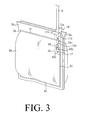
- FIG. 3 is a schematic view, showing an air enclosure of the first embodiment after being filled with air;
- FIG. 4 is a plane view, showing an air enclosure of a second embodiment according to the present invention before being filled with air;
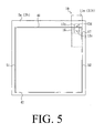
- FIG. 5 is a plane view, showing an air enclosure of a third embodiment being not part of the present invention before being filled with air;
- FIG. 6 is a cross sectional view, showing an air enclosure of the third embodiment being not part of the present invention after being filled with air;
- FIG. 7 is a plane view, showing an air enclosure of a fourth embodiment being not part of the present invention before being filled with air;
- FIG. 8 is a cross sectional view, showing an air enclosure of the fourth embodiment being not part of the present invention after being filled with air;
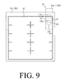
- FIG. 9 is a plane view, showing an air enclosure of a fifth embodiment being not part of the present invention before being filled with air.
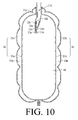
- FIG. 10 is a cross sectional view, showing an air enclosure of the fifth embodiment after being filled with air.
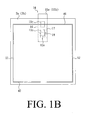
- FIGS. 1A , 1B , 2 and 3 are plane views, showing an air enclosure of a first embodiment before being filled with air.
- FIG. 2 is a cross sectional view, showing an air enclosure of the first embodiment after being filled with air.
- FIG. 3 is a schematic view, showing an air enclosure of the first embodiment after being filled with air.
- An air enclosure capable of being filled with high pressure gas includes at least one air cylinder 20 and at least one check valve 10.
- the air cylinder 20 is formed between the two outer films 2a and 2b by adhering the two sheets of outer film 2a and 2b to each other by means of hot sealing along hot sealing lines 41, 42, 51 and 52. After the two sheets of outer film 2a and 2b are stacked together vertically, it is used for storing air (gas).
- the check valve 10 is placed in between the two sheets of outer film 2a and 2b, and includes the two sheets of first inner film 11 a and 11 b and two sheets of second inner film 12a and 12b, in which parts of the two sheets of first inner film 11 a and 11 b respectively project from the air cylinder 20, and the width of the first inner film 11a (11b) is equal to the width of the second inner film 12a (12b), but the length of the second inner film 12a (12b) is shorter than the length of the first inner film 11a (11 b).
- the two sheets of second inner film 12a and 12b are placed between the two sheets of first inner film 11 a and 11 b after being stacked together vertically, and hot sealing lines 16, 17 and 18 are used to adhere the two sheets of the two sheets of first inner film 11 a and 11 b and the two sheets of second inner film 12a and 12b.
- one side of the first inner film 11a (11b) is aligned with one side of the outer film 2a (2b), and they are adhered together by means of hot sealing to allow the hot sealing line 52 to be overlapped with the hot sealing line 17 as FIG. 1A , and may also allow the two sheets of first inner film 11 a and 11 b to be placed between the hot sealing lines 51 and 52 as FIG. 1B shows.
- the two sheets of second inner films 12a and 12b are positioned between the two sheets of first inner film 11 a and 11 b and at the lower half thereof, i.e. the two sheets of second inner film 12a and 12b are positioned in the air cylinder 20 but the present embodiment is not limited to this.
- the two sheets of second inner film 12a and 12b may be placed between the two sheets of first inner film 11 a and 11 b depending on practical design requirements.
- the thickness of the first inner film 11 a (11 b) is larger than the thickness of the second inner film 12a (12b) but the present embodiment is not limited to this.
- Two sheets of first inner film 11 a and 11 b are not adhered to each other at the hot sealing line 41 to form a first air inlet 11d when the two sheets of outer film 2a and 2b as well as the two sheets of first inner film 11 a and 11 b are adhered together by means of hot sealing along the hot sealing line 41, where a heat resistant material 11c is spread or a heat resistant pad is placed in advance between the two sheets of first inner film 11 a and 11 b to prevent them from adhering to each other during the hot sealing, but the present embodiment is not limited to this.
- the hot sealing line 18 is used to adhere the two sheets of first inner film 11 a and 11 b as well as the two sheets of second inner film 12a and 12b to each other at the top ends of the two sheets of second inner film 12a and 12b or correct locations respectively close to the top ends of thereof, the two sheets of second inner film 12a and 12b are not adhered to each other at the hot sealing line 18 to form a second air inlet 12d, where the heat resistant material 12c may be spread or a heat resistant pad may be placed in advance between the two sheets of second inner film 12a and 12b to prevent them from adhering to each other during the hot sealing, but the present embodiment is not limited to this.
- the two sheets of second inner film 12a and 12b are adhered to each other by means of hot sealing to form a second air passageway 12e connected with the second air inlet 12d between the two sheets of second inner film 12a and 12b, where one end of the second air passageway 12e connected to the second air inlet 12d may be larger than the width of another end thereof to allow air in the second air inlet 12d to enter easily but not to escape easily.
- the shape of the second air passageway 12e is not limited to this; it may also be a curved shape, a mesh shape or a shape capable of being adjusted depending on practical design requirements.
- Internal air pressure of air cylinder 20 compresses the two sheets of first inner film 11 a and 11 b, as well as the two sheets of second inner film 12a and 12b to cover the second air inlet 12 and the second air passageway 12e, shielding the air cylinder 20 after the air enters, preventing air leakage and retaining the air.
- the check valve is protected from breakage by high pressure, while the air enters and is retained, further increasing the air filling speed to reduce the air filling time, through the design of the two sheets of first inner film 11 a and 11b together with the two sheets of second inner film 12a and 12b.
- check valve 10 is hung in the air cylinder 20 after the air bag is filled.
- the check valve 10 is able to attach closely to the air filling tool 9 because the internal air pressure of the air cylinder 20 compresses the check valve 10 when the user takes out the air filling tool 9.
- the check valve 10 may be prevented from being pulled out of the air cylinder 20 after the user takes out the air filling tool 9, by virtue of the fact that one side of the two sheets of first inner film 11 a and 11 b is adhered to one side of the two sheets of outer film 2a and 2b by means of hot sealing.
- FIG. 4 is a plane view, showing an air enclosure of a second embodiment according to the present invention before being filled with air.
- the two sheets of first inner film 11a and 11b are also adhered to each other by means of hot sealing to form a first air passageway 11e connected to the first air inlet 11 d between the two sheets of first inner film 11 a and 11 b, in which the width of one end of the first air passageway 11e connected to the first air inlet 11d may be larger than the width of another end thereof to allow air in the first air inlet 11d to enter easily but not to escape easily.
- the shape of the first air passageway 11e is not limited to this; it may be a curved shape, a mesh shape or a shape capable of being adjusted depending on practical design requirements.
- FIG. 5 is a plane view, showing an air enclosure of a third embodiment being not part of the present invention before being filled with air.
- FIG. 6 is a cross sectional view, showing an air enclosure of the third embodiment being not part of the present invention after being filled with air.
- the two sheets of second inner film 12a and 12b are positioned between the two sheets of first inner film 11 a and 11 b at the upper half part thereof, i.e. at least one part of the two sheets of second inner film 12a and 12b projects from the air cylinder 20, where the top ends of the two sheets of second inner film 12a and 12b are aligned with the top ends of the two sheets of first inner film 11 a and 11 b, and the bottom ends of the two sheets of second inner film 12a and 12b are positioned in the air cylinder 20.
- the present embodiment does not include the structure of the first air inlet 11 d in the first embodiment.
- FIG. 7 is a plane view, showing an air enclosure of a fourth embodiment being not part of the present invention before being filled with air.
- FIG. 8 is a cross sectional view, showing an air enclosure of the fourth embodiment being not part of the present invention after being filled with air.
- Two sets of the two sheets of second inner film 12a and 12b respectively may be positioned between the two sheets of first inner film 11 a and 11 b at the upper half part and the lower half part thereof, i.e. a part of one set of the two sheets of second inner film 12a and 12b among them projects from the air cylinder 20 and another part thereof is placed in the air cylinder 20, and another set of the two sheets of second inner film 12a and 12b is placed below the aforementioned set of the two sheets of second inner film 12a and 12b and completely in the air cylinder 20.
- FIG. 9 is a plane view, showing an air enclosure of a fifth embodiment according to the present before being filled with air.
- FIG. 10 is a cross sectional view, showing an air enclosure of the fifth embodiment after being filled with air.
- the outer film 2a constitutes film sheets 21 a and 22a
- the outer film 2b constitutes two film sheets 21 b and 22b
- the film sheets 21 a and 22a may be hot-sealed to cause parts of the area thereof to adhere to each other
- the film sheets 21 b and 22b may be hot-sealed to cause parts of the area thereof to be adhere to each other so as to strengthen the structure of the two sheets of outer film 2a and 2b, and preventing the two sheets of outer film 2a and 2b from being pierced by a sharp article and subsequently leaking.
- the film sheets 21 a and 22a may be formed with an air storable auxiliary air chamber 23a by means of hot sealing
- the film sheets 21 b and 22b may be formed with an air storable auxiliary air chamber 23b by means of hot sealing, thereby strengthening the cushioning protection effect, and ensuring that the cushioning protection effect of the air cylinder 20 will also not be lost if auxiliary air chambers 23a or 23b are pierced.
- Two first inner and two second inner films stacked together are used to form a check valve in an air enclosure capable of being filled with high pressure air according to the present invention, where the two second inner films are stacked together between the two first inner films thereby strengthening the strength of the check valve to allow the air cylinder to be filled with high pressure air via the check valve, to enabling the air cylinder to be filled with air and expanded quickly without breaking the check valve with high pressure during the air filling process, to ensure air retention, and further increasing the air filling speed, thus reducing the air filling time.
- the present invention may use a plurality of film sheets independent of one another and not glued to one another to form an outer film, thereby strengthening the strength of the outer film. Hence, the cushioning protection effect will not be lost if a film sheet is broken.
Description
- The present invention relates to an air enclosure capable of being filled with high pressure air.
- When large-scale articles are placed in a container for transportation, cushioning air bags will be placed in among the articles so as to protect the articles from impact during transportation to avoid scratching and damage and to increase efficiency during transportation.
- However, the volume of such a cushioning air bag always is very large (in order to provide a good cushioning effect), such that a lot of time needs to be spent to fill it with air; it is rather time and labor wasting. If a cushioning air bag is filled with high pressure gas, breakage of the air bag's check valve is easily caused, making it impossible to retain the air; or the outer film of the air bag is broken, causing air leakage. Moreover, such a cushioning bag is commonly scratched and damaged by a sharp or acute angle of the article in the container, causing air in the cushioning air bag to leak and reducing the cushioning protection effect, which will usually not be discovered until the article is taken out of the container. In the meantime, the article is scratched or damaged because of the lack of a cushioning medium during transportation. Air enclosures are for example known from
JP 01 158477 U DE 20 2006 002935 U1 . - To improve a cushioning air bag, increasing the air filling speed to reduce the time needed to fill the cushioning air bag with air, and further solve the problem of the cushioning air bag being scratched easily by a sharp angle or acute angle of an article in a container (causing air to leak and reducing the cushioning protection effect), by improving the structure of the cushioning air bag, the present invention is proposed.
- The present invention proposes an air enclosure capable of being filled with high pressure air, including:
- two outer films;
- at least one air cylinder, formed between the two outer films by adhering the two outer films to each other by means of hot sealing; and
- a check valve assembled in the at least one air cylinder, the check valve comprising:
- two first inner films, placed in between the two outer films, parts of the two inner films projecting from the air cylinder;
- at least one first air inlet, formed by one of a heat resistant material and a heat resistant pad spread or placed between the first inner films by adhering the first inner films to each other by means of hot sealing;
- at least one first air passageway, connected to the first air inlet and formed between the first inner films by adhering the first inner films to each other by means of hot sealing;
- two second inner films, placed in between the two first inner films, and a length of either second inner film being shorter than a length of either first inner film; and
- at least one second air inlet, formed between the two second inner films by adhering the two second inner films to each other by means of hot sealing, whereby high pressure air can be forced into the second air inlet through an air filling tool and into the air cylinder, causing the air cylinder to fill with air and expand.
- The present invention uses the two first inner films and the two second inner films stacked together to constitute the check valve, where the two second inner films are stacked between the two first inner films so that high pressure air may enter the air cylinder, causing the air cylinder to fill with air and expand. Breakage of the check valve by high pressure while air is entering will not occur, the air can be retained can be achieved, and the air filling speed can further be increased to reduce the time required.
- The present invention can be more fully understood by reference to the following description and accompanying drawings, in which:
-
FIGS. 1A and1B are plane views, showing an air enclosure of a first embodiment being not part of the present invention before being filled with air; -
FIG. 2 is a cross sectional view, showing an air enclosure of the first embodiment after being filled with air; -
FIG. 3 is a schematic view, showing an air enclosure of the first embodiment after being filled with air; -
FIG. 4 is a plane view, showing an air enclosure of a second embodiment according to the present invention before being filled with air; -
FIG. 5 is a plane view, showing an air enclosure of a third embodiment being not part of the present invention before being filled with air; -
FIG. 6 is a cross sectional view, showing an air enclosure of the third embodiment being not part of the present invention after being filled with air; -
FIG. 7 is a plane view, showing an air enclosure of a fourth embodiment being not part of the present invention before being filled with air; -
FIG. 8 is a cross sectional view, showing an air enclosure of the fourth embodiment being not part of the present invention after being filled with air; -
FIG. 9 is a plane view, showing an air enclosure of a fifth embodiment being not part of the present invention before being filled with air; and -
FIG. 10 is a cross sectional view, showing an air enclosure of the fifth embodiment after being filled with air. - Please refer to
FIGS. 1A ,1B ,2 and3 .FIGS. 1A and1B are plane views, showing an air enclosure of a first embodiment before being filled with air.FIG. 2 is a cross sectional view, showing an air enclosure of the first embodiment after being filled with air.FIG. 3 is a schematic view, showing an air enclosure of the first embodiment after being filled with air. - An air enclosure capable of being filled with high pressure gas includes at least one
air cylinder 20 and at least onecheck valve 10. - The
air cylinder 20 is formed between the twoouter films outer film hot sealing lines outer film - The
check valve 10 is placed in between the two sheets ofouter film inner film inner film inner film air cylinder 20, and the width of the firstinner film 11a (11b) is equal to the width of the secondinner film 12a (12b), but the length of the secondinner film 12a (12b) is shorter than the length of the firstinner film 11a (11 b). In addition, the two sheets of secondinner film inner film hot sealing lines inner film inner film inner film 11a (11b) is aligned with one side of theouter film 2a (2b), and they are adhered together by means of hot sealing to allow thehot sealing line 52 to be overlapped with thehot sealing line 17 asFIG. 1A , and may also allow the two sheets of firstinner film hot sealing lines FIG. 1B shows. - In the present embodiment, the two sheets of second
inner films inner film inner film air cylinder 20 but the present embodiment is not limited to this. The two sheets of secondinner film inner film inner film 11 a (11 b) is larger than the thickness of the secondinner film 12a (12b) but the present embodiment is not limited to this. - Two sheets of first
inner film hot sealing line 41 to form afirst air inlet 11d when the two sheets ofouter film inner film hot sealing line 41, where a heatresistant material 11c is spread or a heat resistant pad is placed in advance between the two sheets of firstinner film - The
hot sealing line 18 is used to adhere the two sheets of firstinner film inner film inner film inner film hot sealing line 18 to form asecond air inlet 12d, where the heatresistant material 12c may be spread or a heat resistant pad may be placed in advance between the two sheets of secondinner film inner film second air passageway 12e connected with thesecond air inlet 12d between the two sheets of secondinner film second air passageway 12e connected to thesecond air inlet 12d may be larger than the width of another end thereof to allow air in the second air inlet 12d to enter easily but not to escape easily. However, the shape of thesecond air passageway 12e is not limited to this; it may also be a curved shape, a mesh shape or a shape capable of being adjusted depending on practical design requirements. - When a user wants to fill the bag with air, they first pull the two sheets of first
inner film first air inlet 11 d. The two sheets of secondinner film second air inlet 12d when the two sheets of firstinner film hot sealing line 18 adheres the firstinner film 11a to the secondinner film 12a and the firstinner film 11 b to the secondinner film 12b. The user inserts an air filling tool into thesecond air passageway 12e to fill the bag with high pressure air, and the high pressure air is fillsair cylinder 20, which then expands via thesecond air inlet 12d and thesecond air passageway 12e. Internal air pressure ofair cylinder 20 compresses the two sheets of firstinner film inner film second air passageway 12e, shielding theair cylinder 20 after the air enters, preventing air leakage and retaining the air. The check valve is protected from breakage by high pressure, while the air enters and is retained, further increasing the air filling speed to reduce the air filling time, through the design of the two sheets of firstinner film inner film - One end of the
check valve 10 is hung in theair cylinder 20 after the air bag is filled. Thecheck valve 10 is able to attach closely to theair filling tool 9 because the internal air pressure of theair cylinder 20 compresses thecheck valve 10 when the user takes out theair filling tool 9. In the meantime thecheck valve 10 may be prevented from being pulled out of theair cylinder 20 after the user takes out theair filling tool 9, by virtue of the fact that one side of the two sheets of firstinner film outer film - Please refer to
FIG. 4. FIG. 4 is a plane view, showing an air enclosure of a second embodiment according to the present invention before being filled with air. - In the present embodiment, the two sheets of first
inner film first air inlet 11 d between the two sheets of firstinner film first air inlet 11d may be larger than the width of another end thereof to allow air in thefirst air inlet 11d to enter easily but not to escape easily. However, the shape of the first air passageway 11e is not limited to this; it may be a curved shape, a mesh shape or a shape capable of being adjusted depending on practical design requirements. -
FIG. 5 is a plane view, showing an air enclosure of a third embodiment being not part of the present invention before being filled with air.FIG. 6 is a cross sectional view, showing an air enclosure of the third embodiment being not part of the present invention after being filled with air. - The two sheets of second
inner film inner film inner film air cylinder 20, where the top ends of the two sheets of secondinner film inner film inner film air cylinder 20. The present embodiment does not include the structure of thefirst air inlet 11 d in the first embodiment. - When a user wants to fill the bag with air, they first pull the two sheets of second
inner film second air inlet 12d, and then insert theair filling tool 9 between the two sheets of secondinner film second air passageway 12e, causing theair cylinder 20 to be filled with air and expanded. Internal air pressure of theair cylinder 20 compresses the two sheets of firstinner film inner film second air inlet 12d and thesecond air passageway 12e to shield theair cylinder 20, preventing air leakage and retaining the air. -
FIG. 7 is a plane view, showing an air enclosure of a fourth embodiment being not part of the present invention before being filled with air.FIG. 8 is a cross sectional view, showing an air enclosure of the fourth embodiment being not part of the present invention after being filled with air. - Two sets of the two sheets of second
inner film inner film inner film air cylinder 20 and another part thereof is placed in theair cylinder 20, and another set of the two sheets of secondinner film inner film air cylinder 20. -
FIG. 9 is a plane view, showing an air enclosure of a fifth embodiment according to the present before being filled with air.FIG. 10 is a cross sectional view, showing an air enclosure of the fifth embodiment after being filled with air. - In the present embodiment, the
outer film 2a constitutesfilm sheets outer film 2b constitutes twofilm sheets film sheets film sheets outer film outer film - In addition, the
film sheets auxiliary air chamber 23a by means of hot sealing, and thefilm sheets auxiliary air chamber 23b by means of hot sealing, thereby strengthening the cushioning protection effect, and ensuring that the cushioning protection effect of theair cylinder 20 will also not be lost ifauxiliary air chambers - Two first inner and two second inner films stacked together are used to form a check valve in an air enclosure capable of being filled with high pressure air according to the present invention, where the two second inner films are stacked together between the two first inner films thereby strengthening the strength of the check valve to allow the air cylinder to be filled with high pressure air via the check valve, to enabling the air cylinder to be filled with air and expanded quickly without breaking the check valve with high pressure during the air filling process, to ensure air retention, and further increasing the air filling speed, thus reducing the air filling time. In addition, the present invention may use a plurality of film sheets independent of one another and not glued to one another to form an outer film, thereby strengthening the strength of the outer film. Hence, the cushioning protection effect will not be lost if a film sheet is broken.
- Additional advantages and modifications will readily occur to those skilled in the art. Therefore, the invention in its broader aspects is not limited to the specific details and representative embodiments shown and described herein. Accordingly, various modifications may be made without departing from the scope of the general inventive concept as defined by the appended claims.
Claims (7)
- An air enclosure capable of being filled with high pressure air, comprising:two outer films (2a, 2b);at least one air cylinder (20), formed between the two outer films (2a, 2b) by adhering the two outer films (2a, 2b) to each other by means of hot sealing; anda check valve (10) assembled in the at least one air cylinder (20), the check valve (10) comprising:two first inner films (11 a, 11 b), placed in between the two outer films (2a, 2b), parts of the two first inner films (11a, 11b) projecting from the air cylinder (20);at least one first air inlet (11d), formed by one of a heat resistant material (11c) and a heat resistant pad spread or placed between the first inner films (11a, 11b) by adhering the first inner films (11 a, 11 b) to each other by means of hot sealing;at least one first air passageway (11e), connected to the first air inlet (11d) and formed between the first inner films (11 a, 11 b) by adhering the first inner films (11 a, 11 b) to each other by means of hot sealing;two second inner films (12a, 12b), placed in between the two first inner films (11 a, 11 b), and a length of either second inner film (12a, 12b) being shorter than a length of either first inner film (11a, 11b); andat least one second air inlet (12d), formed between the second inner films (12a, 12b) by adhering the two second inner films (12a, 12b) to each other by means of hot sealing, whereby high pressure air can be forced into the second air inlet (12d) through an air filling tool (9) and into the air cylinder (20), causing the air cylinder (20) to fill with air and expand.
- The air enclosure capable of being filled with high pressure air according to claim 1, wherein one side of the first inner films (11 a, 11 b) is aligned with one side of the outer films (2a, 2b) and adhered to the side of the outer films (2a, 2b) by means of hot sealing.
- The air enclosure capable of being filled with high pressure air according to claim 1, wherein at least one part of the second inner films (12a, 12b) projects from the air cylinder (20).
- The air enclosure capable of being filled with high pressure air according to claim 1, wherein the second inner films (12a, 12b) are positioned in the air cylinder (20).
- The air enclosure capable of being filled with high pressure air according to claim 1, wherein one of a heat resistant material (12c) and a heat resistant pad is spread or placed between the second inner films (12a, 12b) to form the second air inlet (12d) by adhering the second inner films (12a, 12b) to each other by means of hot sealing.
- The air enclosure capable of being filled with high pressure air according to claim 1, further comprising at least one second air passageway (12e) connected to the second air inlet (12d) and formed between the second inner films (12a, 12b) by adhering the second inner films (12a, 12b) to each other by means of hot sealing.
- The air enclosure capable of being filled with high pressure air according to claim 1, wherein the outer films comprise a plurality of film sheets, and the plurality of film sheets are adhered to one another by means of hot sealing to form at least one auxiliary air chamber among the plurality of film sheets.
Applications Claiming Priority (1)
| Application Number | Priority Date | Filing Date | Title |
|---|---|---|---|
| TW97110266A TW200940421A (en) | 2008-03-21 | 2008-03-21 | Air enclosure and check valve capable of being filled with high-pressure air |
Publications (3)
| Publication Number | Publication Date |
|---|---|
| EP2103550A2 EP2103550A2 (en) | 2009-09-23 |
| EP2103550A3 EP2103550A3 (en) | 2010-07-21 |
| EP2103550B1 true EP2103550B1 (en) | 2012-11-14 |
Family
ID=40848125
Family Applications (1)
| Application Number | Title | Priority Date | Filing Date |
|---|---|---|---|
| EP20080164038 Active EP2103550B1 (en) | 2008-03-21 | 2008-09-10 | Air enclosure with check valve capable of being filled with high pressure air |
Country Status (5)
| Country | Link |
|---|---|
| US (1) | US7959003B2 (en) |
| EP (1) | EP2103550B1 (en) |
| JP (1) | JP4928527B2 (en) |
| KR (1) | KR20090101051A (en) |
| TW (1) | TW200940421A (en) |
Families Citing this family (15)
| Publication number | Priority date | Publication date | Assignee | Title |
|---|---|---|---|---|
| US20140224699A1 (en) * | 2001-07-03 | 2014-08-14 | Jack V. Smith | Inflatable box and method of use thereof |
| TW200848328A (en) * | 2007-06-04 | 2008-12-16 | Chieh-Hua Liao | Air packing bag for tightly holding article and manufacturing method thereof |
| CN102381518B (en) * | 2010-09-03 | 2013-12-11 | 廖建华 | Air seal and manufacturing method thereof |
| TWI413608B (en) * | 2011-06-08 | 2013-11-01 | Yaw Shin Liao | Can be a number of gas filling structure |
| JP2013079170A (en) * | 2011-10-04 | 2013-05-02 | Mitsuboshi Diamond Industrial Co Ltd | Scribing method |
| US8910664B2 (en) * | 2012-02-14 | 2014-12-16 | AIRBAG Packing Co, Ltd. | Nonlinear air stop valve structure |
| US8978158B2 (en) * | 2012-04-27 | 2015-03-10 | Google Inc. | Privacy management across multiple devices |
| US9881301B2 (en) | 2012-04-27 | 2018-01-30 | Google Llc | Conversion tracking of a user across multiple devices |
| CN103121543B (en) * | 2013-02-04 | 2014-11-05 | 广东树业环保科技股份有限公司 | Vacuum bag manufacturing method and product of the same |
| US9725066B2 (en) * | 2013-05-04 | 2017-08-08 | Shanghai Air-Paq Composite Material Co., Ltd | Air bag packaging arrangement and self-adhesive checking valve |
| CN105292768B (en) * | 2014-12-31 | 2019-02-22 | 聂会平 | Fluid container and its shut-off valve and manufacturing method |
| US10021808B1 (en) * | 2016-09-23 | 2018-07-10 | Apple Inc. | Integrated bi-directional controlled vent |
| WO2019009139A1 (en) * | 2017-07-04 | 2019-01-10 | 株式会社柏原製袋 | Closing valve made of sheet and bag with closing valve |
| SE542352C2 (en) * | 2018-04-03 | 2020-04-14 | Bengt Pettersson | Valve for air and liquid containers |
| WO2021054148A1 (en) * | 2019-09-18 | 2021-03-25 | Terumo Kabushiki Kaisha | Check valve, cassette having check valve, and method of manufacturing check valve |
Family Cites Families (17)
| Publication number | Priority date | Publication date | Assignee | Title |
|---|---|---|---|---|
| US4267684A (en) * | 1975-09-15 | 1981-05-19 | Ambrose Charles J | Method of packaging delicate articles |
| US4674532A (en) * | 1984-10-30 | 1987-06-23 | Toshimichi Koyanagi | Check valve |
| JPH0314614Y2 (en) * | 1985-12-04 | 1991-04-02 | ||
| JPH01158477A (en) * | 1987-12-16 | 1989-06-21 | Canon Inc | Touching information output apparatus |
| JPH01158477U (en) | 1988-04-20 | 1989-11-01 | ||
| JPH01164177U (en) * | 1988-05-02 | 1989-11-16 | ||
| JPH0624219Y2 (en) * | 1990-03-02 | 1994-06-29 | 株式会社浜田写真工芸社 | Postcard card |
| US5178281A (en) * | 1992-01-21 | 1993-01-12 | S. P. Chemical Co., Ltd. | Cushioning package |
| DE29519421U1 (en) * | 1995-12-08 | 1996-02-22 | Bayyomi Fawzi Ali | Packaging container with flexible walls |
| US5845806A (en) * | 1996-05-29 | 1998-12-08 | Parchman; William J. | Inflatable insulating jacket for beverage container |
| JP4634666B2 (en) * | 2001-08-23 | 2011-02-16 | 有限会社神山包装材料 | Check valve |
| JP2006117311A (en) | 2004-10-25 | 2006-05-11 | Tomematsu Abe | Air shock absorbing material |
| KR200397141Y1 (en) * | 2005-07-13 | 2005-09-28 | (주)에어텍네츄럴 | Air pouring buffering packing structure |
| DE202006002935U1 (en) | 2006-02-23 | 2006-04-20 | Leadpak Industrial Co., Ltd. | Multilayer diaphragm valve arrangement |
| CN100467358C (en) | 2006-03-13 | 2009-03-11 | 廖建华 | Air cushion cylinder having a sealer of air sealing and locking device and the method for preparing the same |
| TW200827254A (en) * | 2006-12-29 | 2008-07-01 | Chieh-Hua Liao | Apparatus and method for manufacturing double layer air cylinder type air enclosure |
| TW200827253A (en) * | 2006-12-29 | 2008-07-01 | Chieh-Hua Liao | Block reinforced air enclosure and manufacture thereof |
-
2008
- 2008-03-21 TW TW97110266A patent/TW200940421A/en not_active IP Right Cessation
- 2008-08-26 US US12/198,822 patent/US7959003B2/en not_active Expired - Fee Related
- 2008-09-10 EP EP20080164038 patent/EP2103550B1/en active Active
- 2008-10-06 KR KR1020080097646A patent/KR20090101051A/en not_active Application Discontinuation
- 2008-11-07 JP JP2008286558A patent/JP4928527B2/en not_active Expired - Fee Related
Also Published As
| Publication number | Publication date |
|---|---|
| EP2103550A3 (en) | 2010-07-21 |
| EP2103550A2 (en) | 2009-09-23 |
| US7959003B2 (en) | 2011-06-14 |
| JP4928527B2 (en) | 2012-05-09 |
| TW200940421A (en) | 2009-10-01 |
| KR20090101051A (en) | 2009-09-24 |
| US20090238496A1 (en) | 2009-09-24 |
| JP2009227336A (en) | 2009-10-08 |
| TWI336307B (en) | 2011-01-21 |
Similar Documents
| Publication | Publication Date | Title |
|---|---|---|
| EP2103550B1 (en) | Air enclosure with check valve capable of being filled with high pressure air | |
| US7913848B2 (en) | Air filling bag with outer film strengthening structure | |
| JP4628432B2 (en) | Gas packaging bag for tightly sandwiching an article and method for manufacturing the same | |
| EP2006217B1 (en) | Method of using air vacuum for binding object by an inflatable packing bag | |
| KR101018979B1 (en) | Multi-sectional clamping type air enclosure | |
| EP1938961B1 (en) | Apparatus and method for manufacturing double layer air cylinder type air enclosure | |
| KR20080063087A (en) | Lock strengthening air enclosure and manufacture thereof | |
| JP4381431B2 (en) | Air seal body having multiple layers of different substrates | |
| CN101462624B (en) | Vacuum suction type gas packing bag and packing method thereof | |
| JP2008074490A (en) | Buffering packing device made of different base materials with a plurality of layers | |
| KR20130132218A (en) | Packing bag with cushioning function | |
| WO2014131137A1 (en) | Box body having inflatable packaging bag | |
| US20090239006A1 (en) | Air enclosure without heat resistant material and manufacturing of same | |
| CN206813671U (en) | A kind of reusable air column bag | |
| CN101746562B (en) | High-pressure aerated air sealing body and air stopping valve thereof | |
| JP2007253981A (en) | Air injecting type cushioning body and conveying container | |
| CN208470559U (en) | Inflating buffer pad | |
| CN105857848A (en) | Anti-roll packaging box | |
| CN216333882U (en) | High-barrier co-extrusion film bubble express bag | |
| TW200831364A (en) | Inflatable gas bag having multiple-sections of gas pockets | |
| CN203997556U (en) | A kind of SCR box assembly packing chest |
Legal Events
| Date | Code | Title | Description |
|---|---|---|---|
| PUAI | Public reference made under article 153(3) epc to a published international application that has entered the european phase |
Free format text: ORIGINAL CODE: 0009012 |
|
| AK | Designated contracting states |
Kind code of ref document: A2 Designated state(s): AT BE BG CH CY CZ DE DK EE ES FI FR GB GR HR HU IE IS IT LI LT LU LV MC MT NL NO PL PT RO SE SI SK TR |
|
| AX | Request for extension of the european patent |
Extension state: AL BA MK RS |
|
| PUAL | Search report despatched |
Free format text: ORIGINAL CODE: 0009013 |
|
| AK | Designated contracting states |
Kind code of ref document: A3 Designated state(s): AT BE BG CH CY CZ DE DK EE ES FI FR GB GR HR HU IE IS IT LI LT LU LV MC MT NL NO PL PT RO SE SI SK TR |
|
| AX | Request for extension of the european patent |
Extension state: AL BA MK RS |
|
| 17P | Request for examination filed |
Effective date: 20110121 |
|
| AKX | Designation fees paid |
Designated state(s): DE FR GB |
|
| 17Q | First examination report despatched |
Effective date: 20110831 |
|
| GRAP | Despatch of communication of intention to grant a patent |
Free format text: ORIGINAL CODE: EPIDOSNIGR1 |
|
| GRAS | Grant fee paid |
Free format text: ORIGINAL CODE: EPIDOSNIGR3 |
|
| GRAA | (expected) grant |
Free format text: ORIGINAL CODE: 0009210 |
|
| AK | Designated contracting states |
Kind code of ref document: B1 Designated state(s): DE FR GB |
|
| REG | Reference to a national code |
Ref country code: GB Ref legal event code: FG4D |
|
| REG | Reference to a national code |
Ref country code: DE Ref legal event code: R096 Ref document number: 602008020072 Country of ref document: DE Effective date: 20130110 |
|
| PLBE | No opposition filed within time limit |
Free format text: ORIGINAL CODE: 0009261 |
|
| STAA | Information on the status of an ep patent application or granted ep patent |
Free format text: STATUS: NO OPPOSITION FILED WITHIN TIME LIMIT |
|
| 26N | No opposition filed |
Effective date: 20130815 |
|
| REG | Reference to a national code |
Ref country code: DE Ref legal event code: R097 Ref document number: 602008020072 Country of ref document: DE Effective date: 20130815 |
|
| REG | Reference to a national code |
Ref country code: FR Ref legal event code: PLFP Year of fee payment: 9 |
|
| REG | Reference to a national code |
Ref country code: FR Ref legal event code: PLFP Year of fee payment: 10 |
|
| REG | Reference to a national code |
Ref country code: FR Ref legal event code: PLFP Year of fee payment: 11 |
|
| PGFP | Annual fee paid to national office [announced via postgrant information from national office to epo] |
Ref country code: FR Payment date: 20190916 Year of fee payment: 12 |
|
| PG25 | Lapsed in a contracting state [announced via postgrant information from national office to epo] |
Ref country code: FR Free format text: LAPSE BECAUSE OF NON-PAYMENT OF DUE FEES Effective date: 20200930 |
|
| PGFP | Annual fee paid to national office [announced via postgrant information from national office to epo] |
Ref country code: DE Payment date: 20210929 Year of fee payment: 14 |
|
| REG | Reference to a national code |
Ref country code: DE Ref legal event code: R119 Ref document number: 602008020072 Country of ref document: DE |
|
| PG25 | Lapsed in a contracting state [announced via postgrant information from national office to epo] |
Ref country code: DE Free format text: LAPSE BECAUSE OF NON-PAYMENT OF DUE FEES Effective date: 20230401 |
|
| PGFP | Annual fee paid to national office [announced via postgrant information from national office to epo] |
Ref country code: GB Payment date: 20230926 Year of fee payment: 16 |