EP2103013B1 - Radio transceiver and method thereof - Google Patents
Radio transceiver and method thereof Download PDFInfo
- Publication number
- EP2103013B1 EP2103013B1 EP08727465.0A EP08727465A EP2103013B1 EP 2103013 B1 EP2103013 B1 EP 2103013B1 EP 08727465 A EP08727465 A EP 08727465A EP 2103013 B1 EP2103013 B1 EP 2103013B1
- Authority
- EP
- European Patent Office
- Prior art keywords
- data
- radio transceiver
- transceiver
- control system
- transmitting
- Prior art date
- Legal status (The legal status is an assumption and is not a legal conclusion. Google has not performed a legal analysis and makes no representation as to the accuracy of the status listed.)
- Active
Links
Images



Classifications
-
- G—PHYSICS
- G08—SIGNALLING
- G08C—TRANSMISSION SYSTEMS FOR MEASURED VALUES, CONTROL OR SIMILAR SIGNALS
- G08C17/00—Arrangements for transmitting signals characterised by the use of a wireless electrical link
- G08C17/02—Arrangements for transmitting signals characterised by the use of a wireless electrical link using a radio link
-
- H—ELECTRICITY
- H04—ELECTRIC COMMUNICATION TECHNIQUE
- H04B—TRANSMISSION
- H04B1/00—Details of transmission systems, not covered by a single one of groups H04B3/00 - H04B13/00; Details of transmission systems not characterised by the medium used for transmission
- H04B1/69—Spread spectrum techniques
- H04B1/713—Spread spectrum techniques using frequency hopping
-
- H—ELECTRICITY
- H04—ELECTRIC COMMUNICATION TECHNIQUE
- H04W—WIRELESS COMMUNICATION NETWORKS
- H04W88/00—Devices specially adapted for wireless communication networks, e.g. terminals, base stations or access point devices
- H04W88/02—Terminal devices
- H04W88/06—Terminal devices adapted for operation in multiple networks or having at least two operational modes, e.g. multi-mode terminals
Definitions
- Embodiments of the present invention generally relate to a wireless control system and method thereof. More specifically, embodiments of the present invention relate to wireless radio transceiver control devices for use in entertainment technology applications, and methods of controlling entertainment fixtures utilizing same.
- Entertainment control systems used in entertainment applications traditionally comprise complex computer-controlled systems utilizing a wide range of stationary and moving lighting and effect devices, otherwise known as fixtures.
- fixtures include, but are not limited to, luminaries, dimmers, stepper motors, fog/ smoke generators, and the like.
- control cables between control devices and one or more fixtures.
- installation of control cables is difficult, time consuming and thus, expensive.
- control cables to not allow for easy connectivity, configuration and often control of individual fixtures, particularly when such connectivity or configuration needs to be modified during a live performance.
- WO2006/012239 A2 discloses methods and apparatus for controlling devices used in entertainment lighting applications and, in particular, a transceiver adapted for incorporation in controllers and controlled devices utilizing industry- standard wired control protocols (e.g., DMX512, RDM, or ACN protocol).
- the transceiver uses wireless broadcasting transmission techniques (e.g., IEEE 802.11 Ethernet Frequency Hopping Spread Spectrum (FHSS) and Direct Sequence Spread Spectrum (DSSS)) and facilitates a bi-directional wireless interface between a controller and controlled devices of a lighting system.
- FHSS Frequency Hopping Spread Spectrum
- DSSS Direct Sequence Spread Spectrum
- EP 1 187 414 A1 discloses a data transmission method and data transmission apparatus. Data are transmitted bi-directionally between two devices and if a side receives a command, it executes an action instructed by the command.
- the used protocol is Bluetooth.
- US 2004/0085941 A1 discloses an information appliance control system that also uses the Bluetooth standard.
- US 2001/0050943 A1 teaches a radio frequency communication network.
- the network includes a multiplicity of mobile transceiver units selectively in communication with a plurality of base transceiver units, which communicate with one or two host computers for storage and manipulation of data collected by barcode scanners or other collection means associated with the mobile transceiver units.
- Embodiments of the present invention generally relate to a wireless control system and method thereof. More specifically, embodiments of the present invention relate to wireless radio transceiver control devices for use in entertainment technology applications, and methods of controlling entertainment fixtures utilizing same.
- a radio transceiver system comprises a control system, a first radio transceiver for transmitting control data formatted in at least an industry- standard control protocol from the control system to at least a second radio transceiver, a second radio transceiver for receiving control data from the first radio transceiver and communicating the same to at least a load, wherein the control data is transmitted from the first radio transceiver to the second radio transceiver utilizing an frequency hopping spread spectrum broadcast, wherein the industry-standard control protocol comprises at least one from the group consisting of DMX512, RDM and ACN.
- a method of transmitting data within a control system comprises initiating a hopping signal from a first transceiver having a constant timing period, transmitting control data from a control system to the first transceiver upon initiation of the hopping signal, transmitting the control data from the first transceiver to a second transceiver on a first frequency, and retransmitting the control data from the first transceiver to the second transceiver on a second frequency.
- the method of transmitting data within an entertainment control system comprises that a hopping sequence for the frequency hopping spread spectrum broadcast is calculated using a function of at least a sequency number and a position in a particular sequence. It may further of advantage, if the second transceiver follows a hopping sequence identical to the hopping sequence of the first transceiver and/or the control data is between about 39 and about 552 bytes and/or the constant timing period of the hopping signal is between about 22.0 mS. and about 23.0 mS, wherein the control data is formatted in at least an industry-standard control protocol comprising at least one from the group consisting of DMX512, RDM and ACN.
- the method comprises performing a cyclic redundancy check on the control data received from the transmission to ensure error-free transmission of the data.
- Embodiments of the present invention generally relate to a radio transceiver system and method thereof. More specifically, embodiments of the present invention relate to wireless radio transceiver control devices for use in the entertainment industry, and methods of controlling entertainment fixtures utilizing same.
- Embodiments of the present invention are intended to be compatible with existing Wireless Data SystemTM (WDS) components, commercially available from City Theatrical, Inc. of Carlstadt, NJ, to alleviate the need to replace an entire control system.
- WDS Wireless Data System
- Exemplary WDS components are disclosed in United States Patent Application Serial No. 11/109,013, filed April 18, 2005 , entitled “Wireless Control System and Method Thereof," published as United States Patent Application Publication No. 2005/0286646 .
- embodiments of the present invention may be plug-compatible with Aerocomm 5124 and Aerocomm-equivalent commands, to accomodate older entertainment systems.
- FIG. 1 depicts a radio transceiver system in accordance with one embodiments of the present invention.
- the system 100 generally comprises a controller 110 (e.g., a DMX controller), at least a controlled device 130 (e.g., a dimmer, a fixture, or the like), a remote controller 120, and a plurality of radio transceivers 200 in accordance with embodiments of the present invention.
- a controller 110 e.g., a DMX controller
- a controlled device 130 e.g., a dimmer, a fixture, or the like
- remote controller 120 e.g., a dimmer, a fixture, or the like
- a remote controller 120 e.g., a dimmer, a fixture, or the like
- the controller 110 generally comprises a specialized or general-purpose computer executing a predefined or interactive program capable of providing instructions to operate and/ or control the controlled devices 130.
- the controller 110 may provide such instructions in accordance with any format or protocol suitable for embodiments of the present invention.
- the communication format utilized by the controller 110 is at least one of several entertainment industry-standard control protocols.
- the controller 110 provides instructions in the DMX512 control protocol developed by the U.S. Institute for Theater Technology, Inc. (USITT) Engineering Commission and adopted by the Entertainment Services and Technology Association (ESTA).
- Each control protocol utilized by embodiments of the present invention may comprise a plurality of independent data/ command channels (e.g., 512 or more channels), where channel corresponds to a specific parameter of a particular controlled device 130, as discussed below in greater detail.
- a controlled device 130 may be any controllable device utilized in a standard entertainment application, or controllable by a radio transceiver system, suitable for embodiments of the present invention.
- the controlled device 130 comprises a fixture, such as a luminaire, dimmer, stepper motor, fog/ smoke generator, light-emitting diode (LED) device, and DMX-controlled device, and the like.
- the controlled device 130 may be controlled using any communication format or protocol suitable for embodiments of the present invention.
- the controlled device 130 may be controlled using the DMX512 control protocol.
- the controlled device 130 may be controlled using a Remote Device Management (RDM) protocol or an Advanced Control Network (ACN) protocol, both developed by the ESTA, or any additional entertainment Ethernet protocol suitable for embodiments of the present invention.
- RDM Remote Device Management
- ACN Advanced Control Network
- the controlled device 130 generally comprises a plurality of controllable parameters, which may vary depending on type of device.
- Exemplary controllable parameters may include: setting of a dimmer, position of a stepper motor, angle of projection of a luminaire, and the like.
- a remote controller 120 is generally a control device acting as an RDM manager of RDM data signals transmitted and received within the system.
- the remote controller 120 may comprise a portable or handheld computer adapted for in-situ operation by service personnel installing, operating and/or monitoring the controlled devices 130. In operation, the remote controller 120 allows remote controllability, configurability and addressability of each controlled device 130, or radio transceiver 200 utilized in the system 100.
- a radio transceiver 200 generally comprises a baseband CPU 210, an RF transceiver 220, a radio amplifier 230, and an antenna 240, and optionally, a power source 260.
- the baseband CPU 210 comprises a processing means, such as a central processing unit, for processing data from a control system (e.g., the controller 110, the remote controller 120, and the like) via an interface 250, and transmitting and receiving data with the RF transceiver 220.
- the baseband CPU 210 comprises a microcontroller having sufficient speed and functionality to meet the demands of buffering, processing, and transferring data at a relatively high continuous rate, as required by embodiments of the present invention.
- the baseband CPU 210 may also comprise direct memory access (DMA) to allow transfer of blocks of data without over-utilizing the processor.
- the baseband CPU 210 comprises a microcontroller, commercially available under the product name AT91SAM7S64, by Atmel Corporation, a Delaware corporation, with a headquarters in San Jose, California.
- the interface 250 comprises any number of ports (not shown) for connecting to any number of inputs from the control system.
- the ports comprise serial ports, USB ports, or the like, capable of transmitting and receiving transmit data (TxD), receive data (RxD), request to send (RTS), and clear to send (CTS) signals.
- the ports comprise a universal asynchronous receiver/transmitter (UART) type connection having at least 40-pin connectors.
- the RF transceiver 220 generally comprises a single chip radio integrated circuit (IC) suitable for performing the necessary functions, as required by embodiments of the present invention.
- the RF transceiver 220 comprises at least one of a half duplex or full duplex transceiver.
- the RF transceiver 220 comprises a half duplex transceiver commercially available under the product name CC2400, by Texas Instruments, Inc., a Delaware corporation, with a headquarters in Dallas, Texas.
- the RF transceiver 220 generally has a transmitting power between about .01mW and about 400mW, as measured by the FCC pre-antenna standards, and in one embodiment has a transmitting power of about 1mW.
- the radio transceiver 200 may comprise a power amplifier (PA) to increase the RF transceiver 220 transmit power where necessary.
- the radio transceiver comprises a power amplifier capable of increasing the RF transceiver 220 transmit power to at least about 1.0W.
- the radio transceiver 200 may optionally comprise a low noise amplifier (LNA) to accommodate the sensitivity of the reception of the RF transceiver 220.
- LNA low noise amplifier
- the radio transceiver 200 may comprise two RF switches to separate the TxD signals and RxD signals. Furthermore, the radio transceiver 200 may additionally comprise a bandpass filter for reducing out-of-band spurious emissions and out-of-band interference for the RF transceiver 220.
- the antenna 240 generally comprises a standard omnidirectional antenna for use in data communication applications.
- the antenna 240 comprises a board-edge mounted coaxial or MMCX type connector.
- Exemplary commercially available antennas for use with embodiments of the present invention include model numbers S151AH-2450S and S141AH-2450, from Nearson Enterprise Corporation, of Taipei, Taiwan, and model number WCP2400-MMCX4, from Laird Technologies (formally Centurion Wireless Technologies), with corporate offices in London, England.
- At least a pair of radio transceivers 200 are utilized in a radio transceiver system in accordance with embodiments of the present invention.
- a first radio transceiver primarily dedicated to transmitting the data from a control system (e.g., a controller 110, etc.) to a receiving device may be termed “transmitter” or “server.”
- a second radio transceiver primarily dedicated to receiving data from a first radio transceiver may be termed a "receiver" or "client.”
- a pair of radio transceivers 200 will solely be operating in either transmitter or receiver mode in accordance with the following disclosure, it is contemplated by embodiments to the present invention to provide each radio transceiver only with such hardware as each respective device would require to operate in such dedicated manner.
- the radio transceiver 200 can operate in a plurality of modes. Generally, in each mode involving transmission of data, the radio transceiver 200 utilizes a Frequency Hopping Spread Spectrum (FHSS) broadcast.
- FHSS Frequency Hopping Spread Spectrum
- the FHSS broadcast format is a highly reliable and robust radio broadcasting technology utilizing an entire broadcast spectrum by rapidly hopping from channel to channel and broadcasting briefly on each one. The order that the radio follows to hop from channel to channel is called the "hopping pattern," and transmitters and associated receivers must be synchronized on the same hopping pattern in order to communicate.
- the radio transceiver 200 utilizes an Adaptive Frequency Hopping Spread Spectrum (AFHSS) broadcast.
- AFHSS Adaptive Frequency Hopping Spread Spectrum
- Such broadcasting in accordance with embodiments of the present invention, generally occurs in the unlicensed 2.4 GHz Industrial Scientific and Medical (ISM) radio band.
- ISM Industrial Scientific and Medical
- the radio transceiver 200 can operate in at least four modes, including: a broadcast mode, half-duplex mode, configuration mode (i.e., testing mode), and sleep mode (i.e., standby).
- the modes may be selected automatically selected based on the data processes occurring in the system.
- the mode may be selected via a switch or pin located on the radio transceiver 200.
- Each mode involving active data transmission is discussed below, in accordance with at least one exemplary embodiment. As is understood by those of ordinary skill in the art, general concepts and alternative embodiments to the exemplary embodiments discussed herein are fully supported by the following disclosure.
- a broadcast mode in accordance with embodiments of the present invention, may be utilized for the transmission from a transmitter (server) or the reception at a receiver (client) of control data, formatted in an industry standard control protocol.
- control data is formatted using the DMX512 communication protocol.
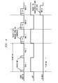
- Figure 3 depicts a timing diagram at a transmitter, representing the data transmission through the transmitter, in accordance with one exemplary embodiment of the present invention.
- the transfer of data from a control system to the transmitter is synchronized by a "HOP" signal which originates from the transmitter.
- the data from each DMX512 packet is first transferred from the control system to the transmitter via the interface and associated ports.
- the DMX512 packet is then transmitted from the transmitter to the receiver, first on one frequency and then again on a next frequency in the hopping pattern.
- the DMX512 data only has to be transferred from the control system to the transmitter once per packet, whereas the transmitter may store the packet for the second transmission on an internal memory.
- the transfer of data from the control system to the transmitter commences when the transmitter toggles the HOP signal from low to high.
- the HOP signal remains high until the beginning of the subsequent hop when the transmitter transmits the redundant packet.
- the transmitter sets the timing of the hopping pattern by transmitting a beacon packet indicating the timing/expected transmission of a packet transmission. Even if the transmitter does not receive an expected amount of data from the control system, a beacon packet is still transmitted to the receiver.
- the beacon packet is generally a short data set, as it represents a header and enough data to indicate to the receiver that it is a beacon packet only. This allows the receiver to stay synchronized with the hopping pattern even where no DMX512 data packets are being transmitted.
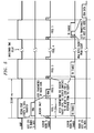
- Figure 4 depicts a timing diagram at a receiver, representing the data transmission to a receiver from a transmitter, in accordance with one exemplary embodiment of the present invention.
- a receiver when a receiver is in broadcast mode, it may be receiving and hopping through a hopping pattern in time with the transmitter.
- a receiver When a receiver is receiving a signal from a transmitter, and is synchronized, it generates the "HOP" signal to indicate the timing hopping pattern. Similar to the timing at the transmitter, the HOP signal goes high at the beginning of every second hop. The toggling of the HOP signal will indicate the receiver is receiving a signal from the transmitter and is synchronized to it, even if there is no data being transmitted.
- the receiver will receive two packets of the same data each with a sequence number (0 or 1).
- the receiver may perform a cyclic redundancy check (CRC) on the first packet to determine if it is acceptable. If it is found unacceptable, the second packet is checked. If one or both of the packets have been received without error, then the errorless packet is allowed to be passed through. If both packets are in error, then the receiver does not transfer any data.
- CRC cyclic redundancy check
- the receiver After the receiver has determined there is an errorless packet, it will start to transfer the received data packet immediately after the HOP signal goes high. If both packets were in error or if no data was received (i.e., only a beacon packet) then the HOP signal will still toggle but there will be no data transferred.
- the total average latency for transmission of a DMX512 packet is between about 40.0ms and about 60.0ms. This delay is reflective of a time period when the transmitter transfers a DMX packet to the receiver until the receiver transfers the same DMX packet to its baseband CPU.
- a half-duplex mode in accordance with embodiments of the present invention, may be utilized where a transmitter is transmitting commands to and receiving replies from a receiver.
- the half-duplex mode may be utilized when RDM commands are used in the system.
- the transmitter first transmits data to a receiver, whereby the receiver may reply, if necessary.
- the half-duplex mode provides the transmitter only transmits each packet once, on the odd hop (i.e., hop 1). On the even hop (i.e., hop 0), the receiver may transmit a reply back to the transmitter.
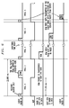
- Figure 5 depicts a timing diagram at a transmitter, representing the data transmission through the transmitter, in accordance with one exemplary embodiment of the present invention. As shown in the Figure, when the transmitter is put into half-duplex mode, the timing of the hopping pattern is not substantially different from the broadcast mode. The transmitter will generally continue to transmit beacon packets every hop so the receiver can stay synchronized.
- the transmitter may expect a data packet from the control system.
- This data packet is generally expected with a particular number of bytes specific to the format and protocol of the data transmission (e.g., normally 257B for RDM protocol transmission).
- the transmitter If the transmitter has not received a complete packet from the control system by the time of the next falling edge of HOP, it will transmit solely a beacon packet. If a complete data packet is received, it will be transmitted on the subsequent falling edge (hop "1").
- the transmitter Upon transmission of a data packet, the transmitter will await a reply from the receiver (although a reply is not always required or received). The reply, if any, will be transmitted from the receiver to the transmitter after the next beacon packet on hop "0".
- Figure 6 depicts a timing diagram at a receiver, representing the data transmission to a receiver from a transmitter, in accordance with one exemplary embodiment of the present invention.
- the receiver may generally be in broadcast mode when it receives the packet from the transmitter because it will not know to change modes unless its own CPU provides such instructions. Thus, to change modes, the receiver will receive a packet of type "half-duplex command" on hop "1," and this data is transferred to the receiver CPU.
- the receiver CPU If the receiver CPU needs to send a reply back to the transmitter then it will switch the receiver into half-duplex mode and send data (e.g., RDM reply) to the transmitter after the appropriate falling edge of the HOP signal.
- data e.g., RDM reply
- a reply is transmitted by the receiver immediately after receiving the next beacon (hop "0") from the transmitter.
- the transmitter will be in half-duplex mode still if it is expecting a reply, will therefore be ready to receive any transmitted data.
- Data packets transmitted with the embodiments of the present invention will generally follow a specific format and timing structure.
- the structure will generally be the same whether the packet is transmitting DMX data, RDM data or some other data.
- the packet type and data length fields will vary accordingly and the length of the data packet may change as well.
- FIG. 7 generally depicts the structure of a data packet, in accordance with embodiments of the present invention.
- a data packet generally comprises a preamble, sync word, data set, and CRC16.
- the preamble, sync word and CRC 16 are added automatically to each data packet transmitted by each radio transceiver.
- the preamble is to allow the receiver time to synchronize with an incoming packet.
- the sync word is to identify to the radio transceiver that the packet is intended for the correct system.
- the CRC16 value will be calculated automatically by the RF transceiver of each radio transceiver, and inserted at the end of the packet.
- the RF transceiver of the receiving device then calculates the CRC16 value on the received data and compares to the transmitted value.
- the baseband CPU of the receiving device will generally check if the CRC value is correct. Any errors found in the CRC16 value will prevent the packet from being passed on to the receiving devices' baseband CPU.
- a data set generally comprises a data header and a data field.
- the data header comprises a packet type, a data length, and a sequence number.
- the data header bits are added by a radio transceiver's baseband CPU to add additional information about the type of packet, length of packet, and indication if the packet is on the odd hop or even hop.
- the data field which carries the relative instructions between radio transceivers, ranges from 33 bytes to 513 bytes, in accordance with embodiments of the present invention.
- the radio transceiver will generally operate in the 2.4 GHz ISM band and will use frequency hopping FSK modulation at an over-the-air data rate of about 1 Mbps.
- the RF signal has a bandwidth of about 1.25 MHz and the channels will be spaced with the center frequencies about 2 MHz apart.
- the 2.4 GHz band covers the range from about 2.40 to about 2.50, and more specifically between about 2.4000 to about 2.4835 GHz. However, leaving guard band at each edge of the band leaves room for 37 channels. Thus, in such an embodiment, the lowest channel is at about 2.406GHz and the highest is at about 2.476GHz.
- the radio transceiver has at least eight different hopping bands within this range that can be selected by the baseband CPU.
- Each band may use even frequencies or odd frequencies.
- This scheme provides some flexibility for choosing different bands to operate simultaneously without interfering with each other. Furthermore, by providing such flexibility, the ability to select a sub-band to avoid other devices such as Wi-Fi.
- a number of different hopping sequences are available for each individual band. For example, in accordance with embodiments of the present invention, 36 sequences are available for the full-bands, and 16 sequences are available for the sub-bands. Each respective sequence has low cross-correlation with every other sequence, thus minimizing the likelihood of interference between a plurality of radio transceivers operating simultaneously within different (or the same) systems. Such an ability to select limited bandwidth in a radio transceiver, to avoid interference from other devices operating in the vicinity, is incomparable in the entertainment industry, and provides a very valuable advantage.
- a transmitter will transmit DMX packets twice on two different channels for redundancy. If the first DMX packet transmission collides with an interfering signal, the receiver may not receive the packet, or at least not an error-free packet. However, the receiver will likely recover the DMX packet on the next hop (i.e., the second transmission), whereas it will be on a different channel.
- the hopping sequences utilized by the radio transceiver is calculated mathematically using hyperbolic codes and they are stored as look-up tables in the firmware.
- One method used to determine the specific time to transmit on each channel utilizes a crystal-controlled timer with a controlled period (e.g., 11.334 ms), and a pseudorandom frequency hopping sequence, as discussed above.
- a crystal-controlled timer with a controlled period (e.g., 11.334 ms), and a pseudorandom frequency hopping sequence, as discussed above.
- a pseudorandom frequency hopping sequence as discussed above.
- a transmitter in broadcast mode begins transmitting beacon packets automatically after coming out of a reset stage. If, for example, DMX data is being transferred to a receiver, then that data will be transmitted as well as the beacon header.
- the transmitter starts its transmission on the first channel of the selected sequence and transmits a packet. When the baseband CPU is interrupted by the timer, the next channel in the sequence is chosen and the next packet is transmitted on that channel. The process continues until the end of the sequence is reached and then it continues from the beginning of the sequence again. This process may be cyclical and will continue until the radio is either powered off, put into a sleep mode or reset.
- a transmitter in half-duplex mode operates almost the same as in broadcast mode.
- One primary difference is that on every alternate hop the transmitter only transmits a beacon packet, and then immediately awaits a reply signal from the receiver for the remaining time on that frequency.
- the timing of the hopping sequence is exactly the same as in broadcast mode.
- the receiver in half-duplex mode normally remains in broadcast mode, i.e., receives packets from a transmitter, until needed, at which time it can transmit reply data packets back to the transmitter.
- the receiver is synchronized with the beacon packets, and will only transmit a data packet back to the transmitter immediately after receiving the beacon packet on a second hop.
- the receiver half-duplex mode will generally only be used when the receiver must respond to a request from the transmitter. Therefore, the transmissions from a receiver will be timed randomly, and will happen on the channel that the system is hopping to at the time.
- a receiver that is meant to be used with a specific transmitter will usually be set to use the same hopping band and hopping sequence as the transmitter. It will also generally have a crystal controlled timer with the same time period. However, when the receiver is first powered on, it will not be synchronized with the transmitter. Generally, the receiver initially starts up in an acquisition phase until it receives a valid server signal and synchronizes with it.
- a receiver in broadcast mode or half-duplex mode will start in the acquisition phase after coming out of a reset.
- acquisition phase the receiver will enable its RF transceiver and start searching for a valid packet from a transmitter on the first channel in a programmed hopping sequence.
- a valid packet will be identified with the correct sync word at the beginning of the packet to indicate that the two radio transceivers are intended to be on the same system. If the receiver does not receive a valid packet on the first channel, it hops to a another channel to look for a valid packet.
- the receiver does not utilize a normal hopping sequence, but rather a modified hopping sequence that results in a quicker acquisition of a valid packet.
- the hopping rate during acquisition is the same as the transmitter uses, within the tolerances of the timer clock.
- the acquisition hopping sequence may be generated by adding an offset to the normal sequence that increments with each hop and also alternates its sign between positive and negative. i.e.:
- this acquisition hopping sequence provides the index for the pseudorandom hopping sequence, it is not the pseudorandom sequence itself. Rather, the index is used with the selected hopping sequence to generate the modified hopping sequence for acquisition.
- the receiver Once the receiver identifies a valid packet from the transmitter, it switches to the normal hopping sequence and synchronizes its timing to the beacon packets. After a receiver has acquired the server beacon packets, it will track the hop timing of the transmitter by constantly measuring the time between packets from the transmitter and adjusting its hop timing to match.
- a receiver If a receiver loses synchronization with its transmitter, it will attempt to resynchronize by one of the following: (1) if no beacon packet is received for 5 hops, it hops to the next channel in the sequence and then waits for 5 hop times looking for a valid beacon packet; (2) if no beacon packet is received in step 1, it starts over at the beginning with the acquisition phase as described above; or (3) if step 2, is unsuccessful and the receiver has missed a count of 240 beacons, then the receiver resets the RF transceiver to an idle state, restarts the receiver and begins the acquisition phase again.
- Additional output features of the radio transceiver include selectable bandwidth hopping (i.e., Full, Limited or Limited Burst Output).
- selectable bandwidth hopping i.e., Full, Limited or Limited Burst Output.
- Full Bandwidth Hopping the radio transceiver will continuously hop across a full ISM band (e.g., 2.4 GHz) spectrum, providing a substantially interference-free delivery mode.
- ISM band e.g., 2.4 GHz
- the radio transceiver is assigned to one of three sub-bands in the full ISM band spectrum. Each sub-band comprises about two-fifths of the full band, with low end, center, and high-end positions. By selecting a sub-band, the radio transceiver may be set to broadcast in a different position of the spectrum than other equipment being used in the area, to minimize or eliminate interference with WiFi channels. In one embodiment, the Limited Bandwidth Hopping mode can be utilized when the radio transceiver is broadcasting at less than about 125 mW output power.
- any contiguous group of 32 or more protocol values may be selected, in multiples of 32 values, and any starting address may be utilized.
- embodiments of the present invention may provide adjustable output power.
- the output power may be adjustable between about 5mW and about 200mW. In another embodiment, the output power may be adjustable between about 10mW and about 125mW.
- embodiments of the present invention are fully scalable to as many transmitters or receivers as may be necessary in a system.
Landscapes
- Engineering & Computer Science (AREA)
- Computer Networks & Wireless Communication (AREA)
- Signal Processing (AREA)
- Physics & Mathematics (AREA)
- General Physics & Mathematics (AREA)
- Mobile Radio Communication Systems (AREA)
- Transceivers (AREA)
Description
- Embodiments of the present invention generally relate to a wireless control system and method thereof. More specifically, embodiments of the present invention relate to wireless radio transceiver control devices for use in entertainment technology applications, and methods of controlling entertainment fixtures utilizing same.
- Entertainment control systems used in entertainment applications (e.g., stage shows, Broadway productions, sporting events, theme parks, etc.) traditionally comprise complex computer-controlled systems utilizing a wide range of stationary and moving lighting and effect devices, otherwise known as fixtures. Known fixtures include, but are not limited to, luminaries, dimmers, stepper motors, fog/ smoke generators, and the like.
- Conventional systems utilize control cables between control devices and one or more fixtures. However, installation of control cables is difficult, time consuming and thus, expensive. Additionally, control cables to not allow for easy connectivity, configuration and often control of individual fixtures, particularly when such connectivity or configuration needs to be modified during a live performance.
- Attempted solutions to wirelessly control such systems have been introduced to the market, utilizing known wireless communication technologies to transmit data between devices. However, many of these attempted solutions fail to account for the existence of the other wireless devices (e.g., computer networks, mobile telephones, walkie-talkies, etc.) also communicating via known wireless communication technologies, and thus, causing interference in the system.
-
WO2006/012239 A2 discloses methods and apparatus for controlling devices used in entertainment lighting applications and, in particular, a transceiver adapted for incorporation in controllers and controlled devices utilizing industry- standard wired control protocols (e.g., DMX512, RDM, or ACN protocol). The transceiver uses wireless broadcasting transmission techniques (e.g., IEEE 802.11 Ethernet Frequency Hopping Spread Spectrum (FHSS) and Direct Sequence Spread Spectrum (DSSS)) and facilitates a bi-directional wireless interface between a controller and controlled devices of a lighting system. -
EP 1 187 414 A1 -
US 2004/0085941 A1 discloses an information appliance control system that also uses the Bluetooth standard. -
US 2001/0050943 A1 teaches a radio frequency communication network. The network includes a multiplicity of mobile transceiver units selectively in communication with a plurality of base transceiver units, which communicate with one or two host computers for storage and manipulation of data collected by barcode scanners or other collection means associated with the mobile transceiver units. - Therefore, an improved entertainment control system, device and method, accounting for such potential interferences, is needed in the industry.
- Embodiments of the present invention generally relate to a wireless control system and method thereof. More specifically, embodiments of the present invention relate to wireless radio transceiver control devices for use in entertainment technology applications, and methods of controlling entertainment fixtures utilizing same.
- In one embodiment, a radio transceiver system comprises a control system, a first radio transceiver for transmitting control data formatted in at least an industry- standard control protocol from the control system to at least a second radio transceiver, a second radio transceiver for receiving control data from the first radio transceiver and communicating the same to at least a load, wherein the control data is transmitted from the first radio transceiver to the second radio transceiver utilizing an frequency hopping spread spectrum broadcast, wherein the industry-standard control protocol comprises at least one from the group consisting of DMX512, RDM and ACN.
- In yet another embodiment, a method of transmitting data within a control system comprises initiating a hopping signal from a first transceiver having a constant timing period, transmitting control data from a control system to the first transceiver upon initiation of the hopping signal, transmitting the control data from the first transceiver to a second transceiver on a first frequency, and retransmitting the control data from the first transceiver to the second transceiver on a second frequency.
- It is of further advantage, if the method of transmitting data within an entertainment control system comprises that a hopping sequence for the frequency hopping spread spectrum broadcast is calculated using a function of at least a sequency number and a position in a particular sequence. It may further of advantage, if the second transceiver follows a hopping sequence identical to the hopping sequence of the first transceiver and/or the control data is between about 39 and about 552 bytes and/or the constant timing period of the hopping signal is between about 22.0 mS. and about 23.0 mS, wherein the control data is formatted in at least an industry-standard control protocol comprising at least one from the group consisting of DMX512, RDM and ACN.
- It may be further of advantage that the method comprises performing a cyclic redundancy check on the control data received from the transmission to ensure error-free transmission of the data.
- So the manner in which the above recited features of the present invention can be understood in detail, a more particular description of embodiments of the present invention, briefly summarized above, may be had by reference to embodiments, which are illustrated in the appended drawings. It is to be noted, however, the appended drawings illustrate only typical embodiments of embodiments encompassed within the scope of the present invention, and, therefore, are not to be considered limiting, for the present invention may admit to other equally effective embodiments, wherein:
-
Figure 1 depicts a radio transceiver system in accordance with one embodiments of the present invention; -
Figure 2 depicts a block diagram of a radio transceiver in accordance with one embodiment of the present invention; -
Figure 3 depicts a timing diagram at a transmitter, representing the data transmission through the transmitter, in accordance with one exemplary embodiment of the present invention; -
Figure 4 depicts a timing diagram at a receiver, representing the data transmission to a receiver from a transmitter, in accordance with one exemplary embodiment of the present invention; -
Figure 5 depicts a timing diagram at a transmitter, representing the data transmission through the transmitter, in accordance with one exemplary embodiment of the present invention; -
Figure 6 depicts a timing diagram at a receiver, representing the data transmission to a receiver from a transmitter, in accordance with one exemplary embodiment of the present invention; and -
Figure 7 generally depicts the structure of a data packet, in accordance with embodiments of the present invention. - The headings used herein are for organizational purposes only and are not meant to be used to limit the scope of the description or the claims. As used throughout this application, the word "may" is used in a permissive sense (i.e., meaning having the potential to), rather than the mandatory sense (i.e., meaning must). Similarly, the words "include", "including", and "includes" mean including but not limited to. To facilitate understanding, like reference numerals have been used, where possible, to designate like elements common to the figures.
- Embodiments of the present invention generally relate to a radio transceiver system and method thereof. More specifically, embodiments of the present invention relate to wireless radio transceiver control devices for use in the entertainment industry, and methods of controlling entertainment fixtures utilizing same.
- Embodiments of the present invention are intended to be compatible with existing Wireless Data System™ (WDS) components, commercially available from City Theatrical, Inc. of Carlstadt, NJ, to alleviate the need to replace an entire control system. Exemplary WDS components are disclosed in United States Patent Application Serial No.
11/109,013, filed April 18, 2005 2005/0286646 . In this regard, embodiments of the present invention may be plug-compatible with Aerocomm 5124 and Aerocomm-equivalent commands, to accomodate older entertainment systems. -
Figure 1 depicts a radio transceiver system in accordance with one embodiments of the present invention. The system 100 generally comprises a controller 110 (e.g., a DMX controller), at least a controlled device 130 (e.g., a dimmer, a fixture, or the like), aremote controller 120, and a plurality ofradio transceivers 200 in accordance with embodiments of the present invention. - The
controller 110 generally comprises a specialized or general-purpose computer executing a predefined or interactive program capable of providing instructions to operate and/ or control the controlleddevices 130. Thecontroller 110 may provide such instructions in accordance with any format or protocol suitable for embodiments of the present invention. - In many embodiments, the communication format utilized by the
controller 110 is at least one of several entertainment industry-standard control protocols. For example, in one embodiment, thecontroller 110 provides instructions in the DMX512 control protocol developed by the U.S. Institute for Theater Technology, Inc. (USITT) Engineering Commission and adopted by the Entertainment Services and Technology Association (ESTA). Each control protocol utilized by embodiments of the present invention may comprise a plurality of independent data/ command channels (e.g., 512 or more channels), where channel corresponds to a specific parameter of a particular controlleddevice 130, as discussed below in greater detail. - A controlled
device 130 may be any controllable device utilized in a standard entertainment application, or controllable by a radio transceiver system, suitable for embodiments of the present invention. In many embodiments, the controlleddevice 130 comprises a fixture, such as a luminaire, dimmer, stepper motor, fog/ smoke generator, light-emitting diode (LED) device, and DMX-controlled device, and the like. - The controlled
device 130 may be controlled using any communication format or protocol suitable for embodiments of the present invention. In one embodiment, the controlleddevice 130 may be controlled using the DMX512 control protocol. In another embodiment, the controlleddevice 130 may be controlled using a Remote Device Management (RDM) protocol or an Advanced Control Network (ACN) protocol, both developed by the ESTA, or any additional entertainment Ethernet protocol suitable for embodiments of the present invention. - The controlled
device 130 generally comprises a plurality of controllable parameters, which may vary depending on type of device. Exemplary controllable parameters may include: setting of a dimmer, position of a stepper motor, angle of projection of a luminaire, and the like. - A
remote controller 120 is generally a control device acting as an RDM manager of RDM data signals transmitted and received within the system. Theremote controller 120 may comprise a portable or handheld computer adapted for in-situ operation by service personnel installing, operating and/or monitoring the controlleddevices 130. In operation, theremote controller 120 allows remote controllability, configurability and addressability of each controlleddevice 130, orradio transceiver 200 utilized in the system 100. - The structure of a
radio transceiver 200 may be described with respect toFigure 2. Figure 2 depicts a block diagram of a radio transceiver in accordance with one embodiment of the present invention. Aradio transceiver 200 generally comprises a baseband CPU 210, an RF transceiver 220, a radio amplifier 230, and an antenna 240, and optionally, a power source 260. - The baseband CPU 210 comprises a processing means, such as a central processing unit, for processing data from a control system (e.g., the
controller 110, theremote controller 120, and the like) via an interface 250, and transmitting and receiving data with the RF transceiver 220. In many embodiments, the baseband CPU 210 comprises a microcontroller having sufficient speed and functionality to meet the demands of buffering, processing, and transferring data at a relatively high continuous rate, as required by embodiments of the present invention. The baseband CPU 210 may also comprise direct memory access (DMA) to allow transfer of blocks of data without over-utilizing the processor. In one embodiment, the baseband CPU 210 comprises a microcontroller, commercially available under the product name AT91SAM7S64, by Atmel Corporation, a Delaware corporation, with a headquarters in San Jose, California. - The interface 250 comprises any number of ports (not shown) for connecting to any number of inputs from the control system. In many embodiments, the ports comprise serial ports, USB ports, or the like, capable of transmitting and receiving transmit data (TxD), receive data (RxD), request to send (RTS), and clear to send (CTS) signals. In one embodiment, the ports comprise a universal asynchronous receiver/transmitter (UART) type connection having at least 40-pin connectors.
- The RF transceiver 220 generally comprises a single chip radio integrated circuit (IC) suitable for performing the necessary functions, as required by embodiments of the present invention. The RF transceiver 220 comprises at least one of a half duplex or full duplex transceiver. In one embodiment, the RF transceiver 220 comprises a half duplex transceiver commercially available under the product name CC2400, by Texas Instruments, Inc., a Delaware corporation, with a headquarters in Dallas, Texas.
- The RF transceiver 220 generally has a transmitting power between about .01mW and about 400mW, as measured by the FCC pre-antenna standards, and in one embodiment has a transmitting power of about 1mW. Optionally, the
radio transceiver 200 may comprise a power amplifier (PA) to increase the RF transceiver 220 transmit power where necessary. In one embodiment, the radio transceiver comprises a power amplifier capable of increasing the RF transceiver 220 transmit power to at least about 1.0W. Similarly, theradio transceiver 200 may optionally comprise a low noise amplifier (LNA) to accommodate the sensitivity of the reception of the RF transceiver 220. - In certain embodiments, where both a PA and a LNA are utilized, the
radio transceiver 200 may comprise two RF switches to separate the TxD signals and RxD signals. Furthermore, theradio transceiver 200 may additionally comprise a bandpass filter for reducing out-of-band spurious emissions and out-of-band interference for the RF transceiver 220. - The antenna 240 generally comprises a standard omnidirectional antenna for use in data communication applications. In several embodiments, the antenna 240 comprises a board-edge mounted coaxial or MMCX type connector. Exemplary commercially available antennas for use with embodiments of the present invention include model numbers S151AH-2450S and S141AH-2450, from Nearson Enterprise Corporation, of Taipei, Taiwan, and model number WCP2400-MMCX4, from Laird Technologies (formally Centurion Wireless Technologies), with corporate offices in London, England.
- Typically, at least a pair of
radio transceivers 200 are utilized in a radio transceiver system in accordance with embodiments of the present invention. In this regard, as is understood by embodiments of the present invention, a first radio transceiver primarily dedicated to transmitting the data from a control system (e.g., acontroller 110, etc.) to a receiving device, may be termed "transmitter" or "server." Conversely, a second radio transceiver primarily dedicated to receiving data from a first radio transceiver may be termed a "receiver" or "client." In applications where a pair ofradio transceivers 200 will solely be operating in either transmitter or receiver mode in accordance with the following disclosure, it is contemplated by embodiments to the present invention to provide each radio transceiver only with such hardware as each respective device would require to operate in such dedicated manner. - In operation, the
radio transceiver 200 can operate in a plurality of modes. Generally, in each mode involving transmission of data, theradio transceiver 200 utilizes a Frequency Hopping Spread Spectrum (FHSS) broadcast. As is generally understood with FHSS technology, the FHSS broadcast format is a highly reliable and robust radio broadcasting technology utilizing an entire broadcast spectrum by rapidly hopping from channel to channel and broadcasting briefly on each one. The order that the radio follows to hop from channel to channel is called the "hopping pattern," and transmitters and associated receivers must be synchronized on the same hopping pattern in order to communicate. - While embodiments of the present invention may generally broadcast data utilizing FHSS broadcast technology, in one embodiment, the
radio transceiver 200 utilizes an Adaptive Frequency Hopping Spread Spectrum (AFHSS) broadcast. Such broadcasting, in accordance with embodiments of the present invention, generally occurs in the unlicensed 2.4 GHz Industrial Scientific and Medical (ISM) radio band. - In many embodiments, the
radio transceiver 200 can operate in at least four modes, including: a broadcast mode, half-duplex mode, configuration mode (i.e., testing mode), and sleep mode (i.e., standby). The modes may be selected automatically selected based on the data processes occurring in the system. In one embodiment, the mode may be selected via a switch or pin located on theradio transceiver 200. Each mode involving active data transmission is discussed below, in accordance with at least one exemplary embodiment. As is understood by those of ordinary skill in the art, general concepts and alternative embodiments to the exemplary embodiments discussed herein are fully supported by the following disclosure. - A broadcast mode, in accordance with embodiments of the present invention, may be utilized for the transmission from a transmitter (server) or the reception at a receiver (client) of control data, formatted in an industry standard control protocol. In one embodiment, the control data is formatted using the DMX512 communication protocol.
-
Figure 3 depicts a timing diagram at a transmitter, representing the data transmission through the transmitter, in accordance with one exemplary embodiment of the present invention. - In one embodiment, the transfer of data from a control system to the transmitter is synchronized by a "HOP" signal which originates from the transmitter. The data from each DMX512 packet is first transferred from the control system to the transmitter via the interface and associated ports. The DMX512 packet is then transmitted from the transmitter to the receiver, first on one frequency and then again on a next frequency in the hopping pattern. By retransmitting the same DMX512 packet on two separate frequencies (i.e., frequency diversity), the chance of error-free reception of each packet by the receiver.
- Generally, the DMX512 data only has to be transferred from the control system to the transmitter once per packet, whereas the transmitter may store the packet for the second transmission on an internal memory. The transfer of data from the control system to the transmitter commences when the transmitter toggles the HOP signal from low to high. The HOP signal remains high until the beginning of the subsequent hop when the transmitter transmits the redundant packet.
- The transmitter sets the timing of the hopping pattern by transmitting a beacon packet indicating the timing/expected transmission of a packet transmission. Even if the transmitter does not receive an expected amount of data from the control system, a beacon packet is still transmitted to the receiver. The beacon packet is generally a short data set, as it represents a header and enough data to indicate to the receiver that it is a beacon packet only. This allows the receiver to stay synchronized with the hopping pattern even where no DMX512 data packets are being transmitted.
-
Figure 4 depicts a timing diagram at a receiver, representing the data transmission to a receiver from a transmitter, in accordance with one exemplary embodiment of the present invention. - In one embodiment, when a receiver is in broadcast mode, it may be receiving and hopping through a hopping pattern in time with the transmitter. When a receiver is receiving a signal from a transmitter, and is synchronized, it generates the "HOP" signal to indicate the timing hopping pattern. Similar to the timing at the transmitter, the HOP signal goes high at the beginning of every second hop. The toggling of the HOP signal will indicate the receiver is receiving a signal from the transmitter and is synchronized to it, even if there is no data being transmitted.
- Generally, if data is being transmitted by the transmitter, the receiver will receive two packets of the same data each with a sequence number (0 or 1). The receiver may perform a cyclic redundancy check (CRC) on the first packet to determine if it is acceptable. If it is found unacceptable, the second packet is checked. If one or both of the packets have been received without error, then the errorless packet is allowed to be passed through. If both packets are in error, then the receiver does not transfer any data.
- After the receiver has determined there is an errorless packet, it will start to transfer the received data packet immediately after the HOP signal goes high. If both packets were in error or if no data was received (i.e., only a beacon packet) then the HOP signal will still toggle but there will be no data transferred.
- In one embodiment, the total average latency for transmission of a DMX512 packet is between about 40.0ms and about 60.0ms. This delay is reflective of a time period when the transmitter transfers a DMX packet to the receiver until the receiver transfers the same DMX packet to its baseband CPU.
- A half-duplex mode, in accordance with embodiments of the present invention, may be utilized where a transmitter is transmitting commands to and receiving replies from a receiver. For example, the half-duplex mode may be utilized when RDM commands are used in the system.
- Generally, in the half-duplex mode, the transmitter first transmits data to a receiver, whereby the receiver may reply, if necessary. In contrast to the broadcast mode, where each packed it transmitted on two consecutive hops for redundancy, the half-duplex mode provides the transmitter only transmits each packet once, on the odd hop (i.e., hop 1). On the even hop (i.e., hop 0), the receiver may transmit a reply back to the transmitter.
-
Figure 5 depicts a timing diagram at a transmitter, representing the data transmission through the transmitter, in accordance with one exemplary embodiment of the present invention. As shown in the Figure, when the transmitter is put into half-duplex mode, the timing of the hopping pattern is not substantially different from the broadcast mode. The transmitter will generally continue to transmit beacon packets every hop so the receiver can stay synchronized. - In the half-duplex mode, between the rising edge and the next falling edge of the HOP signal, the transmitter may expect a data packet from the control system. This data packet is generally expected with a particular number of bytes specific to the format and protocol of the data transmission (e.g., normally 257B for RDM protocol transmission). If the transmitter has not received a complete packet from the control system by the time of the next falling edge of HOP, it will transmit solely a beacon packet. If a complete data packet is received, it will be transmitted on the subsequent falling edge (hop "1"). Upon transmission of a data packet, the transmitter will await a reply from the receiver (although a reply is not always required or received). The reply, if any, will be transmitted from the receiver to the transmitter after the next beacon packet on hop "0".
-
Figure 6 depicts a timing diagram at a receiver, representing the data transmission to a receiver from a transmitter, in accordance with one exemplary embodiment of the present invention. - The receiver may generally be in broadcast mode when it receives the packet from the transmitter because it will not know to change modes unless its own CPU provides such instructions. Thus, to change modes, the receiver will receive a packet of type "half-duplex command" on hop "1," and this data is transferred to the receiver CPU.
- If the receiver CPU needs to send a reply back to the transmitter then it will switch the receiver into half-duplex mode and send data (e.g., RDM reply) to the transmitter after the appropriate falling edge of the HOP signal. A reply is transmitted by the receiver immediately after receiving the next beacon (hop "0") from the transmitter. The transmitter will be in half-duplex mode still if it is expecting a reply, will therefore be ready to receive any transmitted data.
- Data packets transmitted with the embodiments of the present invention will generally follow a specific format and timing structure. The structure will generally be the same whether the packet is transmitting DMX data, RDM data or some other data. The packet type and data length fields will vary accordingly and the length of the data packet may change as well.
-
Figure 7 generally depicts the structure of a data packet, in accordance with embodiments of the present invention. A data packet generally comprises a preamble, sync word, data set, and CRC16. The preamble, sync word andCRC 16 are added automatically to each data packet transmitted by each radio transceiver. The preamble is to allow the receiver time to synchronize with an incoming packet. The sync word is to identify to the radio transceiver that the packet is intended for the correct system. The CRC16 value will be calculated automatically by the RF transceiver of each radio transceiver, and inserted at the end of the packet. The RF transceiver of the receiving device then calculates the CRC16 value on the received data and compares to the transmitted value. The baseband CPU of the receiving device will generally check if the CRC value is correct. Any errors found in the CRC16 value will prevent the packet from being passed on to the receiving devices' baseband CPU. - A data set generally comprises a data header and a data field. The data header comprises a packet type, a data length, and a sequence number. The data header bits are added by a radio transceiver's baseband CPU to add additional information about the type of packet, length of packet, and indication if the packet is on the odd hop or even hop. The data field, which carries the relative instructions between radio transceivers, ranges from 33 bytes to 513 bytes, in accordance with embodiments of the present invention.
- In accordance with one exemplary embodiment of the present invention, the radio transceiver will generally operate in the 2.4 GHz ISM band and will use frequency hopping FSK modulation at an over-the-air data rate of about 1 Mbps. At this data rate the RF signal has a bandwidth of about 1.25 MHz and the channels will be spaced with the center frequencies about 2 MHz apart.
- The 2.4 GHz band covers the range from about 2.40 to about 2.50, and more specifically between about 2.4000 to about 2.4835 GHz. However, leaving guard band at each edge of the band leaves room for 37 channels. Thus, in such an embodiment, the lowest channel is at about 2.406GHz and the highest is at about 2.476GHz.
- In many embodiments, the radio transceiver has at least eight different hopping bands within this range that can be selected by the baseband CPU. Generally, there are at least four different bands to choose from, including: full-band, low-band, mid-band, and high-band. Each band may use even frequencies or odd frequencies. This scheme provides some flexibility for choosing different bands to operate simultaneously without interfering with each other. Furthermore, by providing such flexibility, the ability to select a sub-band to avoid other devices such as Wi-Fi.
- Moreover, for each individual band, a number of different hopping sequences (or patterns) are available. For example, in accordance with embodiments of the present invention, 36 sequences are available for the full-bands, and 16 sequences are available for the sub-bands. Each respective sequence has low cross-correlation with every other sequence, thus minimizing the likelihood of interference between a plurality of radio transceivers operating simultaneously within different (or the same) systems. Such an ability to select limited bandwidth in a radio transceiver, to avoid interference from other devices operating in the vicinity, is incomparable in the entertainment industry, and provides a very valuable advantage.
- During operation, in one embodiment, a transmitter will transmit DMX packets twice on two different channels for redundancy. If the first DMX packet transmission collides with an interfering signal, the receiver may not receive the packet, or at least not an error-free packet. However, the receiver will likely recover the DMX packet on the next hop (i.e., the second transmission), whereas it will be on a different channel.
- In one exemplary embodiment of the present invention, the hopping sequences utilized by the radio transceiver is calculated mathematically using hyperbolic codes and they are stored as look-up tables in the firmware. In one embodiment, the formula used to calculate them is:

Where: p is a prime number; a is the sequence number; k is the position in thesequence - Thus, for the full-band hopping sequences, p = 37 was used to generate 36 different sequences each with 36 channels. For the sub-bands, p = 17 was used to generate 16 different sequences each with 16 channels. Since only 15 channels were required for the sub-bands,
channel 16 of each sequence may be removed. - One method used to determine the specific time to transmit on each channel utilizes a crystal-controlled timer with a controlled period (e.g., 11.334 ms), and a pseudorandom frequency hopping sequence, as discussed above. To implement this method, each of the three different transmission modes (i.e., transmitter broadcast, transmitter half-duplex, and receiver half-duplex) are individually addressed.
- A transmitter in broadcast mode begins transmitting beacon packets automatically after coming out of a reset stage. If, for example, DMX data is being transferred to a receiver, then that data will be transmitted as well as the beacon header. The transmitter starts its transmission on the first channel of the selected sequence and transmits a packet. When the baseband CPU is interrupted by the timer, the next channel in the sequence is chosen and the next packet is transmitted on that channel. The process continues until the end of the sequence is reached and then it continues from the beginning of the sequence again. This process may be cyclical and will continue until the radio is either powered off, put into a sleep mode or reset.
- A transmitter in half-duplex mode operates almost the same as in broadcast mode. One primary difference is that on every alternate hop the transmitter only transmits a beacon packet, and then immediately awaits a reply signal from the receiver for the remaining time on that frequency. However, the timing of the hopping sequence is exactly the same as in broadcast mode.
- The receiver in half-duplex mode normally remains in broadcast mode, i.e., receives packets from a transmitter, until needed, at which time it can transmit reply data packets back to the transmitter. The receiver is synchronized with the beacon packets, and will only transmit a data packet back to the transmitter immediately after receiving the beacon packet on a second hop. However, the receiver half-duplex mode will generally only be used when the receiver must respond to a request from the transmitter. Therefore, the transmissions from a receiver will be timed randomly, and will happen on the channel that the system is hopping to at the time.
- A receiver that is meant to be used with a specific transmitter will usually be set to use the same hopping band and hopping sequence as the transmitter. It will also generally have a crystal controlled timer with the same time period. However, when the receiver is first powered on, it will not be synchronized with the transmitter. Generally, the receiver initially starts up in an acquisition phase until it receives a valid server signal and synchronizes with it.
- In accordance with an exemplary embodiment, a receiver in broadcast mode or half-duplex mode will start in the acquisition phase after coming out of a reset. In acquisition phase, the receiver will enable its RF transceiver and start searching for a valid packet from a transmitter on the first channel in a programmed hopping sequence. A valid packet will be identified with the correct sync word at the beginning of the packet to indicate that the two radio transceivers are intended to be on the same system. If the receiver does not receive a valid packet on the first channel, it hops to a another channel to look for a valid packet. During the acquisition phase, the receiver does not utilize a normal hopping sequence, but rather a modified hopping sequence that results in a quicker acquisition of a valid packet. The hopping rate during acquisition is the same as the transmitter uses, within the tolerances of the timer clock.
- The acquisition hopping sequence may be generated by adding an offset to the normal sequence that increments with each hop and also alternates its sign between positive and negative. i.e.:
- normal index sequence = 0,1, 2, ... 35
- offset = 0,1, -1, 2, -2, ... -17
- The two sequences are added to get:
- acquisition sequence = 0, 2, 1, 5, 2 ...
- While this acquisition hopping sequence provides the index for the pseudorandom hopping sequence, it is not the pseudorandom sequence itself. Rather, the index is used with the selected hopping sequence to generate the modified hopping sequence for acquisition.
- Once the receiver identifies a valid packet from the transmitter, it switches to the normal hopping sequence and synchronizes its timing to the beacon packets. After a receiver has acquired the server beacon packets, it will track the hop timing of the transmitter by constantly measuring the time between packets from the transmitter and adjusting its hop timing to match.
- If a receiver loses synchronization with its transmitter, it will attempt to resynchronize by one of the following: (1) if no beacon packet is received for 5 hops, it hops to the next channel in the sequence and then waits for 5 hop times looking for a valid beacon packet; (2) if no beacon packet is received in
step 1, it starts over at the beginning with the acquisition phase as described above; or (3) ifstep 2, is unsuccessful and the receiver has missed a count of 240 beacons, then the receiver resets the RF transceiver to an idle state, restarts the receiver and begins the acquisition phase again. - Additional output features of the radio transceiver, in accordance with embodiments of the present invention, include selectable bandwidth hopping (i.e., Full, Limited or Limited Burst Output). In Full Bandwidth Hopping, the radio transceiver will continuously hop across a full ISM band (e.g., 2.4 GHz) spectrum, providing a substantially interference-free delivery mode.
- In Limited Bandwidth Hopping, the radio transceiver is assigned to one of three sub-bands in the full ISM band spectrum. Each sub-band comprises about two-fifths of the full band, with low end, center, and high-end positions. By selecting a sub-band, the radio transceiver may be set to broadcast in a different position of the spectrum than other equipment being used in the area, to minimize or eliminate interference with WiFi channels. In one embodiment, the Limited Bandwidth Hopping mode can be utilized when the radio transceiver is broadcasting at less than about 125 mW output power.
- In Limited Burst Output, the number of possible transmission channels is reduced, as well as the level of output power of the radio transceiver. In this mode, any contiguous group of 32 or more protocol values (e.g., DMX values) may be selected, in multiples of 32 values, and any starting address may be utilized.
- Additionally, embodiments of the present invention may provide adjustable output power. In one embodiment, the output power may be adjustable between about 5mW and about 200mW. In another embodiment, the output power may be adjustable between about 10mW and about 125mW.
- While the foregoing is directed to embodiments of the present invention, other and further embodiments of the invention may be devised without departing from the basic scope thereof. For example, embodiments of the present invention are fully scalable to as many transmitters or receivers as may be necessary in a system.
Claims (11)
- A radio transceiver system (100) comprising:a control system (110);a first radio transceiver (200) for transmitting control data formatted in at least an industry-standard control protocol from the control system (110) to at least a second radio transceiver (200);a second radio transceiver (200) for receiving control data from the first radio transceiver (200) and communicating the same to at least a load;wherein
the load comprises at least one of a luminaire, dimmer, stepper motor, fog generator, smoke generator, light-emitting diode (LED) device or other DMX-controlled device; wherein
the control data is transmitted from the first radio transceiver (200) to the second radio transceiver (200) utilizing a frequency hopping spread spectrum broadcast; wherein
the industry-standard control protocol comprises at least one from the group consisting of DMX512, RDM and ACN; wherein
the frequency hopping spread spectrum broadcast comprises a duplicate transmission of a first data packet on two unequal frequencies; characterized in that
the first radio transceiver (200) sets the timing of the hopping pattern by transmitting a beacon packet indicating the timing/expected transmission of a packet transmission]; wherein
even if the first radio transceiver (200) does not receive an expected amount of data from the control system (110), a beacon packet is still transmitted to the second radio transceiver (200). - The radio transceiver system of claim 1, wherein frequency hopping spread spectrum broadcast is an adaptive frequency hopping spread spectrum broadcast.
- The radio transceiver system of claim 1, wherein the frequency hopping spread spectrum broadcast occurs across a sub-band of the 2.4 GHz, representing about two fifths of the 2.4 GHz spectrum.
- A method of transmitting data within an entertainment control system (100) comprising:initiating a hopping signal from a first transceiver having a constant timing period;transmitting control data from a control system to the first transceiver (200) upon initiation of the hopping signal;transmitting the control data from the first transceiver (200) to a second transceiver (200) on a first frequency; andretransmitting the control data from the first transceiver (200) to the second transceiver (200) on a second frequency, characterized in that the control data is formatted in at least an industry-standard control protocol comprises at least one from the group consisting of DMX512, RDM and ACN; characterized in that
the first radio transceiver (200) sets the timing of the hopping pattern by transmitting a beacon packet indicating the timing/expected transmission of a packet transmission; wherein
even if the first radio transceiver (200) does not receive an expected amount of data from the control system (110), a beacon packet is still transmitted to the second radio transceiver (200). - The method of transmitting data within an entertainment control system of claim 4, wherein the transmitting of the control data and the retransmitting of the control data occur within a single timing period of the hopping signal.
- The method of transmitting data within an entertainment control system of claim 4, wherein the first frequency and the second frequency are sequential frequencies in a frequency hopping spread spectrum broadcast.
- The method of transmitting data within an entertainment control system of claim 6, wherein the frequency hopping spread spectrum broadcast occurs across a full 2.4 GHz spectrum.
- The method of transmitting data within an entertainment control system of claim 6, wherein the frequency hopping spread spectrum broadcast occurs across a sub-band of the 2.4 GHz, representing about two-fifths of the 2.4 GHz spectrum.
- The method of transmitting data within an entertainment control system of claim 6, wherein a hopping sequence for the frequency hopping spread spectrum broadcast is calculated using a function of at least a sequence number and a position in a particular sequence.
- The method of transmitting data within an entertainment control system of claim 4, wherein the control data is between about 39 and about 552 bytes.
- The method of transmitting data within an entertainment control system of claim 4, wherein the constant timing period of the hopping signal is between about 22.0 mS. and about 23.0 mS.
Applications Claiming Priority (2)
| Application Number | Priority Date | Filing Date | Title |
|---|---|---|---|
| US88417107P | 2007-01-09 | 2007-01-09 | |
| PCT/US2008/050607 WO2008086408A2 (en) | 2007-01-09 | 2008-01-09 | Radio transceiver and method thereof |
Publications (3)
| Publication Number | Publication Date |
|---|---|
| EP2103013A2 EP2103013A2 (en) | 2009-09-23 |
| EP2103013A4 EP2103013A4 (en) | 2012-01-11 |
| EP2103013B1 true EP2103013B1 (en) | 2016-11-23 |
Family
ID=39609354
Family Applications (1)
| Application Number | Title | Priority Date | Filing Date |
|---|---|---|---|
| EP08727465.0A Active EP2103013B1 (en) | 2007-01-09 | 2008-01-09 | Radio transceiver and method thereof |
Country Status (2)
| Country | Link |
|---|---|
| EP (1) | EP2103013B1 (en) |
| WO (1) | WO2008086408A2 (en) |
Families Citing this family (1)
| Publication number | Priority date | Publication date | Assignee | Title |
|---|---|---|---|---|
| US10485358B2 (en) | 2017-03-28 | 2019-11-26 | Theatre FX, LLC | Systems and methods for simultaneously controlling cinema seats |
Citations (4)
| Publication number | Priority date | Publication date | Assignee | Title |
|---|---|---|---|---|
| EP1187414A1 (en) | 2000-04-12 | 2002-03-13 | Sony Corporation | Data transmission method and data transmission apparatus |
| US20020150147A1 (en) * | 2001-03-03 | 2002-10-17 | Ping Liang | Multichannel signal transmission and reception for bluetooth systems |
| US20050128988A1 (en) | 2003-09-30 | 2005-06-16 | Simpson Floyd D. | Enhanced passive scanning |
| WO2006012239A2 (en) * | 2004-06-25 | 2006-02-02 | City Theatrical, Inc. | Wireless control system and method thereof |
Family Cites Families (5)
| Publication number | Priority date | Publication date | Assignee | Title |
|---|---|---|---|---|
| US20010050943A1 (en) * | 1989-08-03 | 2001-12-13 | Mahany Ronald L. | Radio frequency communication network having adaptive communication parameters |
| AU7210894A (en) * | 1993-06-25 | 1995-01-17 | Xircom, Inc. | Virtual carrier detection for wireless local area network with distributed control |
| US6463090B1 (en) * | 2000-06-19 | 2002-10-08 | Bertrand Dorfman | Communication in high rise buildings |
| US7054301B1 (en) * | 2001-12-31 | 2006-05-30 | Arraycomm, Llc. | Coordinated hopping in wireless networks using adaptive antenna arrays |
| US20040085941A1 (en) * | 2002-11-06 | 2004-05-06 | Pei-Zhi Li | Information appliance control system |
-
2008
- 2008-01-09 EP EP08727465.0A patent/EP2103013B1/en active Active
- 2008-01-09 WO PCT/US2008/050607 patent/WO2008086408A2/en not_active Ceased
Patent Citations (4)
| Publication number | Priority date | Publication date | Assignee | Title |
|---|---|---|---|---|
| EP1187414A1 (en) | 2000-04-12 | 2002-03-13 | Sony Corporation | Data transmission method and data transmission apparatus |
| US20020150147A1 (en) * | 2001-03-03 | 2002-10-17 | Ping Liang | Multichannel signal transmission and reception for bluetooth systems |
| US20050128988A1 (en) | 2003-09-30 | 2005-06-16 | Simpson Floyd D. | Enhanced passive scanning |
| WO2006012239A2 (en) * | 2004-06-25 | 2006-02-02 | City Theatrical, Inc. | Wireless control system and method thereof |
Also Published As
| Publication number | Publication date |
|---|---|
| EP2103013A4 (en) | 2012-01-11 |
| EP2103013A2 (en) | 2009-09-23 |
| WO2008086408A3 (en) | 2008-09-04 |
| WO2008086408A2 (en) | 2008-07-17 |
Similar Documents
| Publication | Publication Date | Title |
|---|---|---|
| US20080170601A1 (en) | Oem radio transceiver and method thereof | |
| US7454218B2 (en) | Method of band multiplexing to improve system capacity for a multi-band communication system | |
| EP1453258B1 (en) | Methods, piconet member and piconet coordinator for controlling frequency hopping sequences by using a beacon specifying a hopping sequence rotation sequence and a hopping sequence | |
| JP4997284B2 (en) | FDD / TDD wireless link for UNII band | |
| US6751251B2 (en) | Fixed frequency transceiver for use in a frequency hopping system | |
| JP4499974B2 (en) | Method and apparatus for minimizing the probability of self-interference between adjacent wireless communication networks | |
| CN101507192B (en) | Radio communication method and radio communication device | |
| CN101461151B (en) | Communicating over a wireless network | |
| EP1583282A1 (en) | Wireless communication system, wireless communication device and wireless communication method, and computer program | |
| US20120002702A1 (en) | Systems and methods for indoor positioning | |
| WO2005027420A1 (en) | Channel access methods and apparatus in low-power wireless communications systems | |
| CN105071831A (en) | Media access control for ultra-wide band communication | |
| EP0745297A1 (en) | Robust frequency management and acquisition in a wireless local area network that uses frequency-hopping radios | |
| KR20110070351A (en) | Multiband wireless communication device and channel allocation method thereof | |
| US11706046B2 (en) | Dynamic superframe slotting | |
| CN105553509B (en) | Interference in frequency hopping radio networks avoids | |
| US20050122948A1 (en) | Communication device, method for controlling communication, game machine, and game system | |
| Radunović et al. | Weeble: Enabling low-power nodes to coexist with high-power nodes in white space networks | |
| US7453843B2 (en) | Wireless bandwidth aggregator | |
| US20070042795A1 (en) | Method of band multiplexing to improve system capacity for a multi-band communication system | |
| WO2008086408A2 (en) | Radio transceiver and method thereof | |
| US10652844B1 (en) | Paging auto-acknowledgement | |
| WO2007064708A2 (en) | Quiet periods for detecting wireless devices | |
| US9979435B1 (en) | System and device for evened frequency emission impact distribution using a preamble-based DSS communication link | |
| CN110035418A (en) | Wireless telecom equipment and related wireless communication method |
Legal Events
| Date | Code | Title | Description |
|---|---|---|---|
| PUAI | Public reference made under article 153(3) epc to a published international application that has entered the european phase |
Free format text: ORIGINAL CODE: 0009012 |
|
| 17P | Request for examination filed |
Effective date: 20090805 |
|
| AK | Designated contracting states |
Kind code of ref document: A2 Designated state(s): AT BE BG CH CY CZ DE DK EE ES FI FR GB GR HR HU IE IS IT LI LT LU LV MC MT NL NO PL PT RO SE SI SK TR |
|
| DAX | Request for extension of the european patent (deleted) | ||
| A4 | Supplementary search report drawn up and despatched |
Effective date: 20111213 |
|
| RIC1 | Information provided on ipc code assigned before grant |
Ipc: G08C 17/02 20060101ALI20111207BHEP Ipc: H04B 1/713 20110101AFI20111207BHEP |
|
| 17Q | First examination report despatched |
Effective date: 20150804 |
|
| REG | Reference to a national code |
Ref country code: DE Ref legal event code: R079 Ref document number: 602008047511 Country of ref document: DE Free format text: PREVIOUS MAIN CLASS: H04H0020470000 Ipc: G08C0017020000 |
|
| GRAP | Despatch of communication of intention to grant a patent |
Free format text: ORIGINAL CODE: EPIDOSNIGR1 |
|
| RIC1 | Information provided on ipc code assigned before grant |
Ipc: H04B 1/713 20110101ALI20160523BHEP Ipc: G08C 17/02 20060101AFI20160523BHEP Ipc: H04W 88/06 20090101ALN20160523BHEP |
|
| INTG | Intention to grant announced |
Effective date: 20160617 |
|
| GRAS | Grant fee paid |
Free format text: ORIGINAL CODE: EPIDOSNIGR3 |
|
| GRAA | (expected) grant |
Free format text: ORIGINAL CODE: 0009210 |
|
| AK | Designated contracting states |
Kind code of ref document: B1 Designated state(s): AT BE BG CH CY CZ DE DK EE ES FI FR GB GR HR HU IE IS IT LI LT LU LV MC MT NL NO PL PT RO SE SI SK TR |
|
| REG | Reference to a national code |
Ref country code: GB Ref legal event code: FG4D |
|
| REG | Reference to a national code |
Ref country code: CH Ref legal event code: EP |
|
| REG | Reference to a national code |
Ref country code: IE Ref legal event code: FG4D |
|
| REG | Reference to a national code |
Ref country code: AT Ref legal event code: REF Ref document number: 848529 Country of ref document: AT Kind code of ref document: T Effective date: 20161215 |
|
| REG | Reference to a national code |
Ref country code: DE Ref legal event code: R096 Ref document number: 602008047511 Country of ref document: DE |
|
| REG | Reference to a national code |
Ref country code: FR Ref legal event code: PLFP Year of fee payment: 10 |
|
| PG25 | Lapsed in a contracting state [announced via postgrant information from national office to epo] |
Ref country code: LV Free format text: LAPSE BECAUSE OF FAILURE TO SUBMIT A TRANSLATION OF THE DESCRIPTION OR TO PAY THE FEE WITHIN THE PRESCRIBED TIME-LIMIT Effective date: 20161123 |
|
| REG | Reference to a national code |
Ref country code: LT Ref legal event code: MG4D |
|
| REG | Reference to a national code |
Ref country code: NL Ref legal event code: MP Effective date: 20161123 |
|
| REG | Reference to a national code |
Ref country code: AT Ref legal event code: MK05 Ref document number: 848529 Country of ref document: AT Kind code of ref document: T Effective date: 20161123 |
|
| PG25 | Lapsed in a contracting state [announced via postgrant information from national office to epo] |
Ref country code: GR Free format text: LAPSE BECAUSE OF FAILURE TO SUBMIT A TRANSLATION OF THE DESCRIPTION OR TO PAY THE FEE WITHIN THE PRESCRIBED TIME-LIMIT Effective date: 20170224 Ref country code: NO Free format text: LAPSE BECAUSE OF FAILURE TO SUBMIT A TRANSLATION OF THE DESCRIPTION OR TO PAY THE FEE WITHIN THE PRESCRIBED TIME-LIMIT Effective date: 20170223 Ref country code: LT Free format text: LAPSE BECAUSE OF FAILURE TO SUBMIT A TRANSLATION OF THE DESCRIPTION OR TO PAY THE FEE WITHIN THE PRESCRIBED TIME-LIMIT Effective date: 20161123 Ref country code: SE Free format text: LAPSE BECAUSE OF FAILURE TO SUBMIT A TRANSLATION OF THE DESCRIPTION OR TO PAY THE FEE WITHIN THE PRESCRIBED TIME-LIMIT Effective date: 20161123 Ref country code: NL Free format text: LAPSE BECAUSE OF FAILURE TO SUBMIT A TRANSLATION OF THE DESCRIPTION OR TO PAY THE FEE WITHIN THE PRESCRIBED TIME-LIMIT Effective date: 20161123 |
|
| PG25 | Lapsed in a contracting state [announced via postgrant information from national office to epo] |
Ref country code: BE Free format text: LAPSE BECAUSE OF NON-PAYMENT OF DUE FEES Effective date: 20170131 Ref country code: ES Free format text: LAPSE BECAUSE OF FAILURE TO SUBMIT A TRANSLATION OF THE DESCRIPTION OR TO PAY THE FEE WITHIN THE PRESCRIBED TIME-LIMIT Effective date: 20161123 Ref country code: PT Free format text: LAPSE BECAUSE OF FAILURE TO SUBMIT A TRANSLATION OF THE DESCRIPTION OR TO PAY THE FEE WITHIN THE PRESCRIBED TIME-LIMIT Effective date: 20170323 Ref country code: PL Free format text: LAPSE BECAUSE OF FAILURE TO SUBMIT A TRANSLATION OF THE DESCRIPTION OR TO PAY THE FEE WITHIN THE PRESCRIBED TIME-LIMIT Effective date: 20161123 Ref country code: HR Free format text: LAPSE BECAUSE OF FAILURE TO SUBMIT A TRANSLATION OF THE DESCRIPTION OR TO PAY THE FEE WITHIN THE PRESCRIBED TIME-LIMIT Effective date: 20161123 Ref country code: AT Free format text: LAPSE BECAUSE OF FAILURE TO SUBMIT A TRANSLATION OF THE DESCRIPTION OR TO PAY THE FEE WITHIN THE PRESCRIBED TIME-LIMIT Effective date: 20161123 Ref country code: FI Free format text: LAPSE BECAUSE OF FAILURE TO SUBMIT A TRANSLATION OF THE DESCRIPTION OR TO PAY THE FEE WITHIN THE PRESCRIBED TIME-LIMIT Effective date: 20161123 |
|
| PG25 | Lapsed in a contracting state [announced via postgrant information from national office to epo] |
Ref country code: EE Free format text: LAPSE BECAUSE OF FAILURE TO SUBMIT A TRANSLATION OF THE DESCRIPTION OR TO PAY THE FEE WITHIN THE PRESCRIBED TIME-LIMIT Effective date: 20161123 Ref country code: CZ Free format text: LAPSE BECAUSE OF FAILURE TO SUBMIT A TRANSLATION OF THE DESCRIPTION OR TO PAY THE FEE WITHIN THE PRESCRIBED TIME-LIMIT Effective date: 20161123 Ref country code: SK Free format text: LAPSE BECAUSE OF FAILURE TO SUBMIT A TRANSLATION OF THE DESCRIPTION OR TO PAY THE FEE WITHIN THE PRESCRIBED TIME-LIMIT Effective date: 20161123 Ref country code: RO Free format text: LAPSE BECAUSE OF FAILURE TO SUBMIT A TRANSLATION OF THE DESCRIPTION OR TO PAY THE FEE WITHIN THE PRESCRIBED TIME-LIMIT Effective date: 20161123 Ref country code: DK Free format text: LAPSE BECAUSE OF FAILURE TO SUBMIT A TRANSLATION OF THE DESCRIPTION OR TO PAY THE FEE WITHIN THE PRESCRIBED TIME-LIMIT Effective date: 20161123 |
|
| REG | Reference to a national code |
Ref country code: DE Ref legal event code: R026 Ref document number: 602008047511 Country of ref document: DE |
|
| PG25 | Lapsed in a contracting state [announced via postgrant information from national office to epo] |
Ref country code: BG Free format text: LAPSE BECAUSE OF FAILURE TO SUBMIT A TRANSLATION OF THE DESCRIPTION OR TO PAY THE FEE WITHIN THE PRESCRIBED TIME-LIMIT Effective date: 20170223 Ref country code: BE Free format text: LAPSE BECAUSE OF FAILURE TO SUBMIT A TRANSLATION OF THE DESCRIPTION OR TO PAY THE FEE WITHIN THE PRESCRIBED TIME-LIMIT Effective date: 20161123 Ref country code: IT Free format text: LAPSE BECAUSE OF FAILURE TO SUBMIT A TRANSLATION OF THE DESCRIPTION OR TO PAY THE FEE WITHIN THE PRESCRIBED TIME-LIMIT Effective date: 20161123 |
|
| REG | Reference to a national code |
Ref country code: CH Ref legal event code: PL |
|
| PLBI | Opposition filed |
Free format text: ORIGINAL CODE: 0009260 |
|
| PG25 | Lapsed in a contracting state [announced via postgrant information from national office to epo] |
Ref country code: MC Free format text: LAPSE BECAUSE OF FAILURE TO SUBMIT A TRANSLATION OF THE DESCRIPTION OR TO PAY THE FEE WITHIN THE PRESCRIBED TIME-LIMIT Effective date: 20161123 |
|
| 26 | Opposition filed |
Opponent name: MANGERSNES, KRISTER Effective date: 20170821 |
|
| PLAX | Notice of opposition and request to file observation + time limit sent |
Free format text: ORIGINAL CODE: EPIDOSNOBS2 |
|
| PG25 | Lapsed in a contracting state [announced via postgrant information from national office to epo] |
Ref country code: LI Free format text: LAPSE BECAUSE OF NON-PAYMENT OF DUE FEES Effective date: 20170131 Ref country code: CH Free format text: LAPSE BECAUSE OF NON-PAYMENT OF DUE FEES Effective date: 20170131 |
|
| REG | Reference to a national code |
Ref country code: IE Ref legal event code: MM4A |
|
| PG25 | Lapsed in a contracting state [announced via postgrant information from national office to epo] |
Ref country code: LU Free format text: LAPSE BECAUSE OF NON-PAYMENT OF DUE FEES Effective date: 20170109 Ref country code: SI Free format text: LAPSE BECAUSE OF FAILURE TO SUBMIT A TRANSLATION OF THE DESCRIPTION OR TO PAY THE FEE WITHIN THE PRESCRIBED TIME-LIMIT Effective date: 20161123 |
|
| REG | Reference to a national code |
Ref country code: FR Ref legal event code: PLFP Year of fee payment: 11 |
|
| PLAF | Information modified related to communication of a notice of opposition and request to file observations + time limit |
Free format text: ORIGINAL CODE: EPIDOSCOBS2 |
|
| PG25 | Lapsed in a contracting state [announced via postgrant information from national office to epo] |
Ref country code: IE Free format text: LAPSE BECAUSE OF NON-PAYMENT OF DUE FEES Effective date: 20170109 |
|
| PLBB | Reply of patent proprietor to notice(s) of opposition received |
Free format text: ORIGINAL CODE: EPIDOSNOBS3 |
|
| PG25 | Lapsed in a contracting state [announced via postgrant information from national office to epo] |
Ref country code: MT Free format text: LAPSE BECAUSE OF NON-PAYMENT OF DUE FEES Effective date: 20170109 |
|
| PG25 | Lapsed in a contracting state [announced via postgrant information from national office to epo] |
Ref country code: HU Free format text: LAPSE BECAUSE OF FAILURE TO SUBMIT A TRANSLATION OF THE DESCRIPTION OR TO PAY THE FEE WITHIN THE PRESCRIBED TIME-LIMIT; INVALID AB INITIO Effective date: 20080109 |
|
| REG | Reference to a national code |
Ref country code: DE Ref legal event code: R100 Ref document number: 602008047511 Country of ref document: DE |
|
| PG25 | Lapsed in a contracting state [announced via postgrant information from national office to epo] |
Ref country code: CY Free format text: LAPSE BECAUSE OF NON-PAYMENT OF DUE FEES Effective date: 20161123 |
|
| PLCK | Communication despatched that opposition was rejected |
Free format text: ORIGINAL CODE: EPIDOSNREJ1 |
|
| PLBN | Opposition rejected |
Free format text: ORIGINAL CODE: 0009273 |
|
| STAA | Information on the status of an ep patent application or granted ep patent |
Free format text: STATUS: OPPOSITION REJECTED |
|
| PG25 | Lapsed in a contracting state [announced via postgrant information from national office to epo] |
Ref country code: TR Free format text: LAPSE BECAUSE OF FAILURE TO SUBMIT A TRANSLATION OF THE DESCRIPTION OR TO PAY THE FEE WITHIN THE PRESCRIBED TIME-LIMIT Effective date: 20161123 |
|
| 27O | Opposition rejected |
Effective date: 20191008 |
|
| PGFP | Annual fee paid to national office [announced via postgrant information from national office to epo] |
Ref country code: DE Payment date: 20200129 Year of fee payment: 13 |
|
| PGFP | Annual fee paid to national office [announced via postgrant information from national office to epo] |
Ref country code: FR Payment date: 20200127 Year of fee payment: 13 |
|
| PG25 | Lapsed in a contracting state [announced via postgrant information from national office to epo] |
Ref country code: IS Free format text: LAPSE BECAUSE OF FAILURE TO SUBMIT A TRANSLATION OF THE DESCRIPTION OR TO PAY THE FEE WITHIN THE PRESCRIBED TIME-LIMIT Effective date: 20170323 |
|
| REG | Reference to a national code |
Ref country code: DE Ref legal event code: R119 Ref document number: 602008047511 Country of ref document: DE |
|
| PG25 | Lapsed in a contracting state [announced via postgrant information from national office to epo] |
Ref country code: FR Free format text: LAPSE BECAUSE OF NON-PAYMENT OF DUE FEES Effective date: 20210131 |
|
| PG25 | Lapsed in a contracting state [announced via postgrant information from national office to epo] |
Ref country code: DE Free format text: LAPSE BECAUSE OF NON-PAYMENT OF DUE FEES Effective date: 20210803 |
|
| REG | Reference to a national code |
Ref country code: GB Ref legal event code: 732E Free format text: REGISTERED BETWEEN 20230727 AND 20230802 |
|
| PGFP | Annual fee paid to national office [announced via postgrant information from national office to epo] |
Ref country code: GB Payment date: 20260127 Year of fee payment: 19 |