EP2102091B1 - System and method for transporting inventory items - Google Patents
System and method for transporting inventory items Download PDFInfo
- Publication number
- EP2102091B1 EP2102091B1 EP07855066.2A EP07855066A EP2102091B1 EP 2102091 B1 EP2102091 B1 EP 2102091B1 EP 07855066 A EP07855066 A EP 07855066A EP 2102091 B1 EP2102091 B1 EP 2102091B1
- Authority
- EP
- European Patent Office
- Prior art keywords
- drive unit
- mobile drive
- housing
- elevating shaft
- operable
- Prior art date
- Legal status (The legal status is an assumption and is not a legal conclusion. Google has not performed a legal analysis and makes no representation as to the accuracy of the status listed.)
- Active
Links
Images





Classifications
-
- B—PERFORMING OPERATIONS; TRANSPORTING
- B66—HOISTING; LIFTING; HAULING
- B66F—HOISTING, LIFTING, HAULING OR PUSHING, NOT OTHERWISE PROVIDED FOR, e.g. DEVICES WHICH APPLY A LIFTING OR PUSHING FORCE DIRECTLY TO THE SURFACE OF A LOAD
- B66F3/00—Devices, e.g. jacks, adapted for uninterrupted lifting of loads
- B66F3/44—Devices, e.g. jacks, adapted for uninterrupted lifting of loads with self-contained electric driving motors
-
- B—PERFORMING OPERATIONS; TRANSPORTING
- B66—HOISTING; LIFTING; HAULING
- B66F—HOISTING, LIFTING, HAULING OR PUSHING, NOT OTHERWISE PROVIDED FOR, e.g. DEVICES WHICH APPLY A LIFTING OR PUSHING FORCE DIRECTLY TO THE SURFACE OF A LOAD
- B66F3/00—Devices, e.g. jacks, adapted for uninterrupted lifting of loads
- B66F3/08—Devices, e.g. jacks, adapted for uninterrupted lifting of loads screw operated
-
- B—PERFORMING OPERATIONS; TRANSPORTING
- B66—HOISTING; LIFTING; HAULING
- B66F—HOISTING, LIFTING, HAULING OR PUSHING, NOT OTHERWISE PROVIDED FOR, e.g. DEVICES WHICH APPLY A LIFTING OR PUSHING FORCE DIRECTLY TO THE SURFACE OF A LOAD
- B66F9/00—Devices for lifting or lowering bulky or heavy goods for loading or unloading purposes
- B66F9/06—Devices for lifting or lowering bulky or heavy goods for loading or unloading purposes movable, with their loads, on wheels or the like, e.g. fork-lift trucks
- B66F9/063—Automatically guided
Definitions
- This invention relates in general to material handling systems, and more particularly, to a method and system for transporting inventory items within an inventory system.
- Modem inventory systems such as those in mail-order and e-commerce warehouses, airport luggage systems, and custom-order manufacturing facilities, face significant challenges in providing fast, accurate responses to requests for inventory items. Delays and backlogs in the process of responding to such inventory requests can result in reduced worker productivity, order cancellations, reduced throughput, or other losses. In recent years, automation has improved the speed and efficiency of storing and retrieving inventory items within such systems. Nonetheless, in high volume systems, the speed and efficiency of automated systems may still limit the overall effectiveness of automated systems.
- An inventory system with a mobile drive unit and inventory holder can be found in WO 2006/044108 .
- an inventory system that utilizes improved techniques for transporting inventory holders.
- a mobile drive unit for transporting inventory items includes a housing, a drive module, a docking module, an elevating shaft, and a rotation module.
- the drive module is capable of propelling the mobile drive unit in at least a first direction.
- the docking head is capable of coupling to or supporting an inventory holder.
- the rotation module is capable of inducing rotation in the housing relative to the elevating shaft.
- the elevating shaft connects to the docking head and is capable of raising the docking head when the housing is rotated relative to the elevating shaft.
- a method for transporting inventory items includes positioning a mobile drive unit beneath an inventory holder at a first location.
- the mobile drive unit includes a housing, a docking head, and an elevating shaft.
- the docking head is connected to the elevating shaft, and the elevating shaft is capable of raising the docking head when the housing is rotated relative to the elevating shaft.
- the method also includes raising the docking head with the elevating shaft by rotating the housing relative to the elevating shaft and docking the mobile drive unit with the inventory holder so that the docking head couples to or supports the inventory holder. Additionally, the method includes moving the mobile drive unit and the inventory holder to a second location.
- FIGURE 1 illustrates an inventory system 10 for storing, sorting, and retrieving inventory items 40 that includes a mobile drive unit 20 and an inventory holder 30.
- Inventory holder 30 stores multiple inventory items 40 of various item types.
- Mobile drive unit 20 moves inventory holder 30 between designated points within a workspace associated with inventory system 10.
- mobile drive unit 20 supports certain techniques for transporting inventory holder 30 that may result in reduced transport times for inventory items 40, reduced power usage, more refined control of inventory holders 30 during transport, and/or other benefits.
- Mobile drive unit 20 is capable of moving within the workspace of inventory system 10 and may include any appropriate components for propelling itself and navigating to a particular destination within the workspace. Additionally, mobile drive unit 20 may dock with inventory holder 30 so that inventory holder 30 is coupled to and/or supported by mobile drive unit 20. When docked with inventory holder 30, mobile drive unit 20 is also capable of propelling and/or otherwise moving inventory holder 30. Mobile drive unit 20 may include any appropriate components for docking with inventory holder 30 and for maneuvering inventory holder 30 while inventory holder 30 is docked with mobile drive unit 20. The components of particular embodiments of mobile drive unit 20 are described in greater detail below with respect to FIGURES 2A-2B and 3A-3D .
- Inventory holder 30 stores inventory items 40 on or within inventory holder 30.
- inventory holder 30 includes multiple storage bins with each storage bin capable of holding inventory items 40. Additionally, in particular embodiments, inventory items 40 hang from hooks or bars within or on inventory holder 30.
- inventory holder 30 may store inventory items 40 in any appropriate manner within inventory holder 30 and/or on the external surface of inventory holder 30. Inventory holder 30 is capable of being rolled, carried, or otherwise moved by mobile drive unit 20.
- FIGURE 1 shows, for the sake of simplicity, only a single inventory holder 30, inventory system 10 may include any appropriate number of inventory holders 30. As a result, inventory holder 30 may represent one of several inventory holders 30 storing inventory items 40 in inventory system 10.
- Inventory items 40 represent any objects suitable for storage, retrieval, and/or processing in an automated inventory system 10.
- inventory system 10 may represent a mail order warehouse facility, and inventory items 40 may represent merchandise stored in the warehouse facility.
- inventory system 10 may represent a merchandise-return facility, and inventory items 40 may represent merchandise returned by customers.
- inventory system 10 may represent a manufacturing facility, and inventory items 40 may represent individual components of a manufacturing kit to be assembled into a finished product, such as electronic components for a customized computer system. More generally, however, inventory items 40 may represent any appropriate objects that may be stored and retrieved in inventory system 10.
- mobile drive unit 20 may, in particular embodiments, be capable of docking with multiple inventory holders 30 simultaneously and/or docking with additional inventory holders 30 after docking with a first inventory holder 30.
- mobile drive units 20 and inventory holders 30 may be configured to allow multiple different mobile drive units 20 to dock with a single inventory holder 30 or group of inventory holders 30.
- mobile drive unit 20 may be used to transport other types of objects and equipment in other types of systems.
- inventory holders 30 may, in particular embodiments, hold other appropriate objects suitable for storage in inventory holder 30.
- inventory holder 30 may also be replaced by vacuum cleaners, floor sweepers, inventory checking units, or other suitable equipment, which mobile drive unit 20 may transport within inventory system 10 or other types of systems.
- mobile drive unit 20 is capable of moving between points within a workspace associated with inventory system 10 and, when coupled to inventory holder 30, of transporting inventory holder 30 between locations within the workspace.
- Mobile drive unit 20 may determine the movement of mobile drive unit 20 autonomously and/or based on commands received by mobile drive unit 20. For example, in particular embodiments, mobile drive unit 20 may receive information that identifies destinations for mobile drive unit 20 from a management device of inventory system 10, from an operator of inventory system 10, or any other suitable party or device. Mobile drive unit 20 may receive the information through a wireless interface, over a wired connection, or using any other suitable components to communicate with an operator or management device of inventory system 10.
- mobile drive unit 20 may use fixed objects, such as fiducial marks, located in the workspace as reference points to assist in navigation.
- mobile drive unit 20 may be configured to detect fiducial marks and to determine the location of mobile drive unit 20 and/or measure its movement based on the detection of fiducial marks.
- movement of mobile drive unit 20 may, depending on the configuration of mobile drive unit 20 and inventory system 10, be controlled, in whole or in part, by mobile drive unit 20, or any appropriate external devices or parties.
- mobile drive unit 20 wirelessly receives orders, data, instructions, commands, or information structured in any other appropriate form, referred to here as a "command" or “commands,” from a remote component of inventory system 10. These commands identify a particular inventory holder 30 to be moved by mobile drive unit 20 and/or a current location for that inventory holder 30, and a destination for that inventory holder 30. Mobile drive unit 20 then controls operation of motors, wheels, and/or other components of mobile drive unit 20 to move mobile drive unit 20 and/or inventory holder 30.
- mobile drive unit 20 moves to a storage location identified by the command.
- Mobile drive unit 20 may then initiate a docking process with the identified inventory holder 30.
- Mobile drive unit 20 may dock with inventory holder 30 in any appropriate manner so that inventory holder 30 is coupled to and/or supported by mobile drive unit 20 when mobile drive unit 20 is docked with inventory holder 30.
- mobile drive unit 20 docks with inventory holder 30 by positioning itself beneath inventory holder 30 and raising a docking head of mobile drive unit 20 until the docking head lifts inventory holder 30 off the ground.
- mobile drive unit 20 include an elevating shaft 202 attached to docking head 204.
- mobile drive unit 20 may raise docking head 204 by rotating some or all of the remainder of mobile drive unit 20 relative to elevating shaft 202.
- mobile drive unit 20 may also perform additional steps to maintain the orientation of docking head 204 while mobile drive unit 20 is rotating elevating shaft 202 relative to mobile drive unit 20.
- elevating shaft 202 comprises a screw or other form of threaded shaft that is raised or lowered when certain portions of mobile drive unit 20 are rotated relative to the screw or threaded shaft. Consequently, in such embodiments, mobile drive unit 20 may raise elevating shaft 202 by driving in a circle while the orientation of elevating shaft 202 is fixed.
- mobile drive unit 20 may support none, some, or all of the weight of inventory holder 30. Additionally, in particular embodiments, one or more components of mobile drive unit 20 may grasp, connect to, interlock with, or otherwise interact with one or more components of inventory holder 30 to form a coupling between mobile drive unit 20 and inventory holder 30.
- docking head 202 may include one or more spines that fit within apertures of inventory holder 30 when mobile drive unit 20 docks with inventory holder 30, allowing mobile drive unit 20 to maneuver inventory holder 30 by applying force to inventory holder 30.
- docking head 202 may include a high-friction surface that abuts a high-friction surface of inventory holder 30 when mobile drive unit 20 is docked with inventory holder 30.
- mobile drive unit 20 may utilize friction forces induced between the abutting surfaces to move and rotate inventory holder 30.
- mobile drive unit 20 may move inventory holder 30 to a second location, such as an inventory station, where inventory items 40 may be removed from inventory holder 30 (e.g., to be packed for shipping), added to inventory holder 30 (e.g., to replenish the supply of inventory items 40 available in inventory system 10), counted, or otherwise processed.
- Mobile drive unit 20 may navigate between the first and second location using any appropriate techniques.
- mobile drive unit 20 is capable of moving inventory holder 30 along a two-dimensional grid, combining forward and backward movement along straight-line segments with ninety-degree rotations and arcing paths to transport inventory holder 30 from the first location to the second location. Additionally, while moving forward or backwards, mobile drive unit 20 may also be capable of performing smaller rotational movements to make navigational corrections or otherwise adjust its heading. When mobile drive unit 20 rotates, mobile drive unit 20 may maintain the orientation of docking head 204. Techniques for achieving this are described in greater detail below with respect to FIGURES 2A-2C and 3A-3D .
- Maintaining the orientation of the docking head 204 while mobile drive unit 20 rotates may prevent the docked inventory holder 30 from colliding with other nearby inventory holders 30, particularly where inventory system 10 utilizes a densely-packed workspace and relies upon components to perform precisely-constrained movements.
- mobile drive unit 20 may undock from inventory holder 30.
- Mobile drive unit 20 may undock from inventory holder 30 in any appropriate manner based on the configuration and characteristics of mobile drive unit 20.
- docking head 204 is attached to an elevating shaft 202 that is raised and lowered in response to the rotation of some or all of the remainder of mobile drive unit 20.
- mobile drive unit 20 may lower docking head 204 by rotating elevating shaft 202 relative to the remainder of mobile drive unit 20.
- mobile drive unit 20 may raise docking head 204 by rotating the relevant portion of mobile drive unit 20 in a first direction relative to elevating shaft 202 and lower docking head 204 by rotating the relevant portion of mobile drive unit 20 in a second direction relative to elevating shaft 202.
- mobile drive unit 20 may move away from inventory holder 30. Mobile drive unit 20 may then begin performing other tasks within inventory system 10.
- mobile drive unit 20 is capable of transporting any of a plurality of inventory holders 30 between locations within inventory system 10 for purposes of fulfilling orders or completing other tasks involving inventory items 40.
- mobile drive unit 20 is able to dock and undock from inventory holder 30 by rotating elevating shaft 202 relative to mobile drive unit 20, particular embodiments of mobile drive unit 20 may be able to dock and undock from inventory holders 30 in less time and using less power. Furthermore, configuring mobile drive unit 20 to utilize the described rotation movement for docking and undocking with inventory holder 30 may make it possible to reduce the number of mechanical parts included in mobile drive unit 20, as discussed further below. In addition, by maintaining the orientation of inventory holder 30 while rotating, mobile drive unit 20 may maneuver inventory holder 30 without inventory holder 30 colliding with other nearby inventory holders. As a result, particular embodiments of mobile drive unit 20 may provide multiple benefits. Alternative embodiments, however, may provide some, none, or all of these benefits.
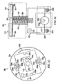
- FIGURES 2A and 2B are side and top views, respectively, of a particular embodiment of mobile drive unit 20.
- FIGURES 2A and 2B illustrate a mobile drive unit 20a that includes elevating shaft 202, docking head 204, a drive module 206, a rotation module 208, a load control module 210, and a processing module 212. Some or all of these components are enclosed in a housing 200.
- Housing 200 encloses and/or connects to one or more of drive module 206, rotation module 208, load control module 210, and processing module 212.
- housing 200 may represent all or a portion of the physical components of any one or more of drive module 206, rotation module 208, load control module 210, and processing module 212.
- Housing 200 may comprise any appropriate material.
- housing represents a metal or plastic casing that encloses components of drive module 206, rotation module 208, load control module 210, and processing module 212, and includes a cavity that holds elevating shaft 202.
- Docking head 204 couples mobile drive unit 20 to inventory holder 30 and/or supports inventory holder 30 when mobile drive unit 20 is docked to inventory holder 30. Docking head 204 may additionally allow mobile drive unit 20a to maneuver inventory holder 30, such as by lifting inventory holder 30, propelling inventory holder 30, rotating inventory holder 30, and/or moving inventory holder 30 in any other appropriate manner. Docking head 204 may also include any appropriate combination of components, such as ribs, spikes, and/or corrugations, to facilitate such manipulation of inventory holder 30. For example, in particular embodiments, docking head 204 may include a high-friction portion that abuts a portion of inventory holder 30 while mobile drive unit 20a is docked to inventory holder 30.
- frictional forces created between the high-friction portion of docking head 204 and a surface of inventory holder 30 may induce translational and rotational movement in inventory holder 30 when docking head 204 moves and rotates, respectively.
- mobile drive unit 20a may be able to manipulate inventory holder 30 by moving or rotating docking head 204, either independently or as a part of the movement of mobile drive unit 20a as a whole.
- Elevating shaft 202 attaches docking head 204 to the remainder of mobile drive unit 20a and is capable of raising and/or lowering docking head 204.
- Elevating shaft 202 may include or represent any element capable of being raised or lowered as a result of rotation induced in elevating shaft 202 or portions of mobile drive unit 20a in contact with elevating shaft 202.
- elevating shaft 202 may represent a shaft or other element that, when rotated, rises as a result of threading on its surface and/or as the result of bearings or other rolling elements following a sloped track within the cavity that holds elevating shaft 202.
- elevating shaft 202 may represent a threaded shaft that rests in a threaded cavity within housing 200.
- elevating shaft 202 may represent any appropriate component or components configured to raise or lower as a result of the rotation of housing 200 and/or elevating shaft 202.
- Drive module 206 (shown in FIGURE 2A only) propels mobile drive unit 20a and, when mobile drive unit 20a and inventory holder 30 are docked, inventory holder 30.
- Drive module 206 may represent any appropriate collection of components operable to propel drive module 206.
- drive module 206 includes a pair of actuators 222 (222a and 22b), a pair of motorized wheels 224 (224a and 224b), and a pair of stabilizing wheels 226 (226a and 226b).
- An actuator 222 is responsible for rotating each of motorized wheels 224.
- drive module 206 may move mobile drive unit 20a in a forward direction relative to a particular face of mobile drive unit 20a by rotating motorized wheels 224 clockwise and in a backward direction relative to that face by rotating motorized wheels 224 counter-clockwise.
- mobile drive unit 20a may include an actuator that is capable of rotating motorized wheels 224 in only a single direction and may utilize a differential drive system to rotate itself.
- mobile drive unit 20 may achieve backward motion by rotating one-hundred and eighty degrees and then moving forward.
- drive module 206 may include any appropriate components capable of moving mobile drive unit 20 in any manner suitable for use in inventory system 10.
- Rotation module 208 induces rotation in all, or a portion of, mobile drive unit 20a relative to elevating shaft 202.
- This rotation may represent any rotation of the relevant portion of mobile drive unit 20a and/or any rotation of elevating shaft 202 such that the orientation of the relevant portion of mobile drive unit 20a changes relative to elevating shaft 202.
- mobile drive unit 20a raises docking head 204 towards inventory holder 30 to facilitate docking of mobile drive unit 20a and inventory holder 30.
- rotation module 208 raises docking head 204 by inducing rotation in mobile drive unit 20a relative to elevating shaft 202 and/or rotation in elevating shaft 202 relative to mobile drive unit 20a.
- Rotation module 208 may represent any appropriate collection of components operable to rotate mobile drive unit 20a and/or elevating shaft 202.
- rotation module 208 may include or represent some or all of the components of drive module 206. This may reduce the number of components in mobile drive unit 20a, making mobile drive unit 20a less expensive to manufacture.
- rotation module 208 of mobile drive unit 20a includes actuators 222a and 22b.
- mobile drive unit 20a rotates mobile drive unit 20a relative to elevating shaft 202 by using actuators 222a and 222b to rotate motorized wheels 224 in opposite directions.
- drive module 206 may include only a single actuator for moving mobile drive unit 20a.
- rotation module 208 may include this single actuator and a differential drive system that interacts with the actuator to rotate mobile drive unit 20a.
- mobile drive unit 20 may, in general, include any appropriate components capable of rotating the mobile drive unit 20 in any manner suitable for use in inventory system 10.
- Load control module 210 controls the orientation of an inventory holder 30 to which mobile drive unit 20a is docked.
- load control module 210 may control the orientation of the relevant inventory holder 30 by adjusting or maintaining the orientation of elevating shaft 202 and/or docking head 204.
- Load control module 210 may include any appropriate components, based on the configuration of mobile drive unit 20a and inventory holder 30, for adjusting the orientation of elevating shaft 202, docking head 204, and/or other appropriate components of mobile drive unit 20a.
- Load control module 210 may adjust the orientation of docking head 204 to rotate a docked inventory holder 30, for example, to present a particular face of the inventory holder 30 to a user. Additionally, as described in greater detail below, load control module 210 may maintain the orientation of docking head 204 while the remainder of mobile drive unit 20 is rotating to prevent any rotation in the docked inventory holder 30.
- load control module 210 includes an actuator 222c capable of applying a torque to elevating shaft 202.
- actuator 222c may be capable of inducing a rotation in elevating shaft 202 to change the orientation of inventory holder 30.
- actuator 222c may also be capable of applying a torque to elevating shaft 202 that counteracts a torque induced by the rotation of the remainder of mobile drive unit 20a.
- load control module 210 may be capable of maintaining an orientation of inventory holder 30 while mobile drive unit 20a is rotating.
- load control module 210 may represent, in part, a portion of rotation module 208, such as an actuator that is responsible for driving motorized wheels 224 and that is coupled to load control module 210 through a clutch mechanism. When the clutch is engaged, the actuator can provide a counter-rotational torque to elevating shaft 202 that maintains the orientation of elevating shaft 202 and/or docking head 204 despite any rotation in the remainder of mobile drive unit 20.
- Processing module 212 monitors and/or controls operation of drive module 206, rotation module 208, and load control module 210. Processing module 212 may also receive information from sensors and adjust the operation of drive module 206, rotation module 208, load control module 210, and/or other components of mobile drive unit 20a based on this information. More specifically, processing module 212 may generate control signals and transmit these control signals to the various components of mobile drive unit 20a to initiate any or all of their described functionality. Additionally, in particular embodiments, mobile drive unit 20a may be configured to communicate with a management device of inventory system 10, and processing module 212 may receive commands transmitted to mobile drive unit 20a and communicate information back to the management device utilizing appropriate communication components of mobile drive unit 20a.
- Processing module 212 may include any appropriate hardware and/or software suitable to provide the described functionality.
- processing module 212 includes a general-purpose microprocessor programmed to provide the described functionality. Additionally, processing module 212 may include all or portions of drive module 206, rotation module 208, and/or load control module 210, and/or share components with any of these elements of mobile drive unit 20a.
- mobile drive unit 20a may provide a number of operational benefits. For example, the rotation movement used by particular embodiments of mobile drive unit 20a to dock with inventory holder 30 may reduce the time and energy utilized in docking. Additionally, in particular embodiments, load control module 210 may allow portions of mobile drive unit 20a to rotate (e.g., for purposes of docking or turning) without changing the orientation of an inventory holder 30 with which mobile drive unit 20a is docked. As a result, particular embodiments of mobile drive unit 20a may reduce or eliminate collisions between the docked inventory holder 30 and other nearby inventory holders while mobile drive unit 20a is rotating. Nonetheless, while mobile drive unit 20a may provide such benefits, particular embodiments may provide some, none, or all such benefits.
- FIGURE 2C illustrates the operation of mobile drive unit 20a when rotating.
- FIGURE 2C shows an example of how mobile drive unit 20a may rotate while maintaining a substantially constant orientation for docking head 204.
- actuators 222a and 222b operate to rotate mobile drive unit 20a in a counter-clockwise direction, while actuator 222c maintains the orientation of docking head 204 (as reflected by the position of mark 234 in FIGURES 2B and 2C ).
- actuator 222a applies a torque (shown in FIGURE 2C by arrow 230a) to motorized wheel 224a
- actuator 222b applies a torque (shown in FIGURE 2C by arrow 230b) to motorized wheel 224b
- the rotation of motorized wheels 224a and 224b causes housing 200 and/or other portions of mobile drive unit 20a to rotate (as shown by arrow 232c).
- actuator 222c applies a torque (shown in FIGURE 2C by arrow 230c) to elevating shaft 202.
- the torque applied to elevating shaft 202 by actuator 222c counteracts any torque applied to elevating shaft 222c as a result of the rotation of housing 200 or other portions of mobile drive unit 20a.
- the torque applied by actuator 222c also lifts docking head 204 and any load on docking head 204, the force applied by actuator 222c may be different in magnitude from the torque applied to housing 200 by actuators 222a and 22b.
- the orientation of docking head 204 remains substantially constant despite the rotation of housing 200 or other portions of mobile drive unit 20a. This is illustrated by the similar position of mark 234 in FIGURES 2B and 2C .
- processing module 212 may be responsible for monitoring and controlling the operation of the various actuators 222 to insure that the torque applied by actuator 222c substantially counteracts the torque applied by actuators 222a and 222b so that docking head 204 experiences no substantial net rotational velocity.
- the torque applied by each of the various actuators 222a-c may be dynamically determined during operation.
- actuators 222a-c may each be configured to provide a torque of a predetermined magnitude chosen so that, overall, the various torques applied by actuators 222a-c produce no rotation in docking head 204.
- FIGURES 3A and 3B are side and top views, respectively, of an alternative embodiment of mobile drive unit 20. Specifically, FIGURES 3A and 3B illustrate a mobile drive unit 20b that includes an alternative embodiment of load control module. In the embodiment of mobile drive unit 20b illustrated by FIGURES 3A and 3B , illustrated components represent components similar in content and operation to any similarly-numbered components in FIGURES 2A and 2B .
- Load control module 310 controls the orientation of an inventory holder 30 to which mobile drive unit 20b is docked.
- load control module 310 includes a braking element 312 that prevents the rotation of docking head 204 when processing module 212 activates braking element 312.
- Braking element 312 may represent any appropriate components suitable to passively inhibit the rotation of docking head 204 once activated.
- an example configuration of braking element 312 includes one or more feet 314 that are attached to docking head 204.
- feet 314 When braking element 312 is activated, feet 314 are pressed against the surface on which mobile drive unit 20b is resting (as shown in FIGURE 3C ).
- feet 314 apply a torque to docking head 204 that counters the torque that is applied by the rotation of mobile drive unit 20b. Consequently, mobile drive unit 20b, or a portion of mobile drive unit 20b, rotates without the orientation of the docked inventory holder 30 changing.
- braking element 312 may include feet 314 that are positioned outside housing 200 and that extend wide of housing 200 when activated. Nonetheless, braking element 312 may, in alternative embodiments, include feet 314 that are positioned within an inner cavity of housing 200 and that extend through this cavity within housing 200 when activated. Feet 314 may be extensible or capable of sliding to maintain contact with the surface. More generally, as noted above, braking element 312 may include any appropriate elements configured in any appropriate manner to inhibit the rotation of docking head 204 when activated.
- FIGURES 3C and 3D illustrate the operation of mobile drive unit 20b when rotating.
- FIGURES 3C and 3D show from the side and top, respectively, an example of how mobile drive unit 20b may rotate while maintaining the orientation of docking head 204 substantially constant.
- actuators 222a and 222b operate to rotate mobile drive unit 20b in a counter-clockwise direction, while braking element 312 maintains the orientation of docking head 204 (as reflected by the position of mark 334 in FIGURES 3B and 3D ).
- actuator 222a applies a torque (shown in FIGURE 3D by arrow 330a) to motorized wheel 224a
- actuator 222b applies a torque (shown in FIGURE 3D by arrow 330b) to motorized wheel 224b.
- the rotation of motorized wheels 224a and 224b causes housing 200 and/or other portions of mobile drive unit 20b to rotate (as shown by arrow 332c).
- processing module 212 or another element of mobile drive unit 20b activates braking element 312.
- Mobile drive unit 20b is illustrated in FIGURE 3C with braking element 312 activated.
- the embodiment of braking element 312 included in mobile drive unit 20b comprises one or more feet 314 that may be deployed when braking element 312 is activated. When feet 314 are deployed, feet 314 press against the surface on which mobile drive unit 20b is resting. Friction between feet 314 and the relevant surface may prevent feet 314 from moving while housing 200 and/or other elements of mobile drive unit 20b rotate.
- feet 314 may each apply a torque to docking head 204 (shown in FIGURE 3D by arrows 330c and 33d) that opposes any torque applied by the rotation of housing 200 or other portions of mobile drive unit 20b. Consequently, the orientation of docking head 204 may remain substantially constant despite the rotation of housing 200 or other portions of mobile drive unit 20b. This is illustrated by the similar position of mark 234 in FIGURES 3B and 3D .
- elevating shaft 202 may represent or incorporate any components suitable to lift docking head 204 in response to rotation of all or a portion of housing 200 relative to elevating shaft 202.
- FIGURES 4A-4D and 5A-5C illustrate further example configurations of elevating shaft 202 that may be used in particular embodiments of mobile drive unit 20.
- FIGURES 4A-4D and 5A-5C illustrate certain examples embodiments and configurations, elevating shaft 202 and mobile drive unit 20 in general may incorporate or include any appropriate components configured in any suitable manner to provide the functionality described herein.
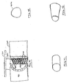
- FIGURES 4A-4D illustrate the components of a particular embodiment of mobile drive unit 20 that utilizes bearings 404 to facilitate the rotation of elevating shaft 202 and housing 200 relative to one another.
- FIGURE 4A shows a partial cutaway view of an embodiment of mobile drive unit 20 that utilizes a recirculating ball screw to raise or lower elevating shaft 202.
- the example embodiment illustrated in FIGURE 4A includes races 402a and 402b, one or more bearings 404, and a recirculating path 406.
- Races 402 comprise pathways in which bearings, rollers, or other rolling or sliding contact elements can move.
- mobile drive unit 20 includes both an inner race 402a and an outer race 402b.
- inner race 402a may represent a portion of elevating shaft 202
- outer race 402b may represent a portion of housing 200.
- bearings 404 may be in contact with one or both of inner race 402a and outer race 402b while rolling or sliding within races 402.
- either or both of races 402 may be sloped to facilitate the elevation of elevating shaft 202.
- Bearings 404 may represent any form of bearings, rollers, or other components capable of rolling along or within races 402 and, in particular embodiments, may abut or contact either or both of races 402 while rolling.
- bearings 404 may be lubricated or made of a low-friction material to facilitate movement along races 402. In general, however, bearings 404 may be comprised of any appropriate material.
- FIGURE 4A illustrates a particular embodiment of mobile drive unit 20 in which bearings 404 represent ball bearings 404a having a substantially spherical shape (as shown in FIGURE 4B ), bearings 404 may represent rolling components of any appropriate shape.
- FIGURES 4C and 4D illustrate two example of bearings 404 that may used in alternative embodiments of mobile drive unit 20. More specifically, FIGURE 4C illustrates a roller bearing 404b having a substantially cylindrical shape, and FIGURE 4D illustrates a tapered roller bearing 404c having the shape of a tapered cylinder.
- Recirculating path 406 comprises a pathway through mobile drive unit 20 that connects one endpoint of outer race 402b with the other endpoint of outer race 402b.
- Recirculating path 406 is sized and shaped to allow bearings 404 to pass between the two endpoints.
- FIGURE 4A includes recirculating path 406 for purposes of illustration, particular embodiments of mobile drive unit 20 may be configured to operate without any recirculating path 406.
- inner race 402a and outer race 402b rotate relative to one another when mobile drive unit 20 rotates housing 200. As a result of the slope of one or both races 402, this rotation also raises or lowers elevating shaft 202.
- Bearings 404 situated between inner race 402a and outer race 402b may reduce friction forces that inhibit the relative rotation of elevating shaft 202 and housing 200. Consequently, the inclusion of bearings 404 may reduce the amount of torque required for mobile drive unit 20 to raise docking head 204 and may reduce the amount of energy and/or time expended in raising or lowering loads supported by docking head 204.
- mobile drive unit 20 may also include recirculating path 206 connecting one endpoint of outer race 402b with the other endpoint of outer race 402b.
- the relative rotation of inner race 402a and outer race 402b may cause bearings 404 to move along races 402.
- the rotation of races 402 carries a particular bearing 404 beyond one of the endpoints of outer race 402b
- the movement of other bearings along races 402 may force the relevant bearing 404 into and through recirculating path 406.
- the relevant bearing 404 is eventually circulated back to the other endpoint of outer race 402b where that bearing 404 re-enters outer race 402b.
- FIGURE 5A-5C illustrate the components of a particular embodiment of mobile drive unit 20 that utilizes pinned rollers 504 to facilitate the rotation of elevating shaft 202 and housing 200 relative to one another.
- FIGURE 5A shows a partial cutaway view of such an embodiment of mobile drive unit 20.
- the example embodiment illustrated in FIGURE 5A includes one or more rollers 504 and a race 502.
- race 502 represents a pathway over which rollers 504 or other rolling or sliding contact elements can move.
- race 502 represents an inner surface of housing 200
- rollers 504 may be attached to housing 200 and race 502 may represent a surface of elevating shaft 202.
- race 502 is sloped to raise or lower elevating shaft 202 as elevating shaft 202 and housing 200 rotate relative to one another.
- the slope of race 502 may not be constant, and race 502 may include one or more plateaus (not shown) at appropriate locations along race 502.
- rollers 504 when elevating shaft 202 is fully extended, rollers 504 may all be located in the middle of one of these plateaus.
- mobile drive unit 20 may then be able to perform small rotations without raising or lowering elevating shaft 202.
- Rollers 504 may represent any appropriate components of any suitable shape attached to either elevating shaft 202 or housing 200 and capable of rolling along race 502. Rollers 504 may be attached to elevating shaft 202 or to housing 200 in any suitable manner.
- FIGURES 5B and 5C show front and side views, respectively, of one embodiment of roller 504 in which roller 504 represents a cylindrical disk. As show in FIGURE 5A , in particular embodiments, rollers 504 are pinned to elevating shaft 202 by bolts or other suitable fasteners (represented in FIGURES 5A-5C by pins 506).
- elevating shaft 202 rotates relative to race 502 when mobile drive unit 20 rotates housing 200.
- rollers 504 roll along race 502. Because race 502 is sloped, rollers 504 rise or fall as they traverse race 502. Furthermore, because rollers 504 are pinned to elevating shaft 202 this also causes elevating shaft 202 to rise or fall.
- use of this rolling action to raise and lower elevating shaft 202 may result in lower friction forces than in embodiments of mobile drive unit 20 that utilize a conventional screw. Consequently, the inclusion of rollers 504 may also reduce the amount of torque required for mobile drive unit 20 to raise docking head 204 and may reduce the amount of energy and/or time expended in raising or lowering loads supported by docking head 204.
- FIGURE 6 is a flowchart illustrating example operation of a particular embodiment of mobile drive unit 20. Some of the steps illustrated in FIGURE 6 may be combined, modified, or deleted where appropriate, and additional steps may also be added to the flowchart. Additionally, the steps may be performed in any suitable order without departing from the scope of the invention.
- operation begins with mobile drive unit 20 positioning itself beneath a selected inventory holder at a first location at step 600.
- mobile drive unit 20 may begin a docking process.
- mobile drive unit 20 may raise docking head 204 at step 610.
- mobile drive unit 20 raises docking head 204 by rotating housing 200 in a first direction relative to elevating shaft 202.
- Mobile drive unit 20 may then execute any other appropriate steps to complete the docking process based on the configuration of mobile drive unit 20 and the selected inventory holder 30.
- mobile drive unit 20 is coupled to and/or supports the inventory holder 30.
- Mobile drive unit 20 may then move the selected inventory holder 30 to a destination where inventory items 40 may be picked from inventory holder 30, replenished, counted, or otherwise processed and/or where inventory holder 30 may be stored until used by inventory system.
- mobile drive unit 20 is capable of moving in a forward and backward direction and rotating.
- mobile drive unit 20 moves to the destination by performing an appropriate combination of straight-line movements and rotations.
- mobile drive unit 20 may maintain the orientation of the selected inventory holder 30 to prevent the selected inventory holder 30 from colliding with other objects or components in inventory system 10.
- FIGURE 6 An example of this movement is shown in FIGURE 6 at steps 620-650. More specifically, while moving the selected inventory holder 30 to the destination, mobile drive unit 20 moves in a first direction at step 620. At step 630, mobile drive unit 20 applies a first torque to its housing 200 using, at least in part, a first actuator 222. Furthermore, at step 640, mobile drive unit 20 applies a second torque to elevating shaft 202 using, at least in part, a second actuator 222, so that an orientation of docking head 204 remains substantially constant while first actuator 222 applies the first torque to housing 200. As a result, the first torque causes housing 200 (including, in this example, drive module 206, rotation module 208, and processing module 212) to rotate and take on a different orientation.
- housing 200 including, in this example, drive module 206, rotation module 208, and processing module 212
- mobile drive unit 20 changes its orientation without changing the orientation of inventory holder 30.
- Mobile drive unit 20 may then move in a second direction at step 650.
- mobile drive unit 20 may rotate inventory holder 30 to present a particular face of inventory holder 30 to an operator of inventory system 10, for example, to allow the operator to select an inventory holder 30 from a bin accessible through the presented face.
- mobile drive unit 20 may rotate both mobile drive unit 20 and inventory holder 30. This is illustrated in FIGURE 6 at steps 660-670.
- mobile drive unit 20 applies a torque to housing 200 at step 660 using the first actuator 222. While applying this torque, mobile drive unit 20 does not apply any torque to elevating shaft 202 to counteract the torque applied to housing 200. As a result, the applied torque rotates both mobile drive unit 20 and inventory holder 30 at step 670.
- mobile drive unit 20 may move the selected inventory holder 30 to a storage location or another final destination at step 680.
- mobile drive unit 20 then lowers docking head 204 by rotating housing 200 in a second direction relative to elevating shaft 202 at step 690.
- Mobile drive unit 20 may then execute any other appropriate steps to complete the undocking process based on the configuration of mobile drive unit 20 and the selected inventory holder 30. As a result of this undocking process, mobile drive unit 20 is no longer coupled to or supports the inventory holder 30.
- Mobile drive unit 20 may then move away from the selected inventory holder 30, at step 700, and begin completing other tasks within inventory system 10 or elsewhere. Operation of mobile drive unit 20 with respect to transporting the selected inventory holder 30 may then end as shown in FIGURE 6 .
Landscapes
- Engineering & Computer Science (AREA)
- Structural Engineering (AREA)
- Life Sciences & Earth Sciences (AREA)
- Geology (AREA)
- Mechanical Engineering (AREA)
- Transportation (AREA)
- Civil Engineering (AREA)
- Warehouses Or Storage Devices (AREA)
Description
- This invention relates in general to material handling systems, and more particularly, to a method and system for transporting inventory items within an inventory system.
- Modem inventory systems, such as those in mail-order and e-commerce warehouses, airport luggage systems, and custom-order manufacturing facilities, face significant challenges in providing fast, accurate responses to requests for inventory items. Delays and backlogs in the process of responding to such inventory requests can result in reduced worker productivity, order cancellations, reduced throughput, or other losses. In recent years, automation has improved the speed and efficiency of storing and retrieving inventory items within such systems. Nonetheless, in high volume systems, the speed and efficiency of automated systems may still limit the overall effectiveness of automated systems. One example of an inventory system with a mobile drive unit and inventory holder can be found in
WO 2006/044108 . - In accordance with the present invention, the disadvantages and problems associated with inventory systems have been substantially reduced or eliminated. In particular, an inventory system is provided that utilizes improved techniques for transporting inventory holders.
- In accordance with one embodiment of the present invention, a mobile drive unit for transporting inventory items includes a housing, a drive module, a docking module, an elevating shaft, and a rotation module. The drive module is capable of propelling the mobile drive unit in at least a first direction. The docking head is capable of coupling to or supporting an inventory holder. The rotation module is capable of inducing rotation in the housing relative to the elevating shaft. The elevating shaft connects to the docking head and is capable of raising the docking head when the housing is rotated relative to the elevating shaft.
- In accordance with another embodiment of the present invention, a method for transporting inventory items includes positioning a mobile drive unit beneath an inventory holder at a first location. The mobile drive unit includes a housing, a docking head, and an elevating shaft. The docking head is connected to the elevating shaft, and the elevating shaft is capable of raising the docking head when the housing is rotated relative to the elevating shaft. The method also includes raising the docking head with the elevating shaft by rotating the housing relative to the elevating shaft and docking the mobile drive unit with the inventory holder so that the docking head couples to or supports the inventory holder. Additionally, the method includes moving the mobile drive unit and the inventory holder to a second location.
- Technical advantages of certain embodiments of the present invention include an inventory-moving apparatus that increases system throughput, reduces power usage, and utilizes fewer mechanical parts. Additionally, particular embodiments of the present invention may support improved techniques for transporting and manipulating inventory storage components. Other technical advantages of the present invention will be readily apparent to one skilled in the art from the following figures, descriptions, and claims. Moreover, while specific advantages have been enumerated above, various embodiments may include all, some, or none of the enumerated advantages.
- For a more complete understanding of the present invention and its advantages, reference is now made, by way of example, to the following description, taken in conjunction with the accompanying drawings, in which:
-
FIGURE 1 illustrates an inventory storage system according to a particular embodiment; -
FIGURES 2A-2C present various views of a particular embodiment of a mobile drive unit that may be used in the inventory storage system; -
FIGURES 3A-3D present various views of an alternative embodiment of the mobile drive unit; -
FIGURES 4A-4D illustrate example components and configurations for particular embodiments of the mobile drive unit; -
FIGURES 5A-5C illustrate example components and configurations for additional embodiments of the mobile drive unit; and -
FIGURE 6 is a flowchart illustrating example operation of a particular embodiment of the mobile drive unit in moving an inventory holder between locations within the inventory system. -
FIGURE 1 illustrates aninventory system 10 for storing, sorting, and retrievinginventory items 40 that includes amobile drive unit 20 and aninventory holder 30. Inventory holder 30 storesmultiple inventory items 40 of various item types.Mobile drive unit 20 movesinventory holder 30 between designated points within a workspace associated withinventory system 10. In particular embodiments,mobile drive unit 20 supports certain techniques for transportinginventory holder 30 that may result in reduced transport times forinventory items 40, reduced power usage, more refined control ofinventory holders 30 during transport, and/or other benefits. -
Mobile drive unit 20 is capable of moving within the workspace ofinventory system 10 and may include any appropriate components for propelling itself and navigating to a particular destination within the workspace. Additionally,mobile drive unit 20 may dock withinventory holder 30 so thatinventory holder 30 is coupled to and/or supported bymobile drive unit 20. When docked withinventory holder 30,mobile drive unit 20 is also capable of propelling and/or otherwise movinginventory holder 30.Mobile drive unit 20 may include any appropriate components for docking withinventory holder 30 and for maneuveringinventory holder 30 whileinventory holder 30 is docked withmobile drive unit 20. The components of particular embodiments ofmobile drive unit 20 are described in greater detail below with respect toFIGURES 2A-2B and3A-3D . - Inventory holder 30
stores inventory items 40 on or withininventory holder 30. In particular embodiments,inventory holder 30 includes multiple storage bins with each storage bin capable of holdinginventory items 40. Additionally, in particular embodiments,inventory items 40 hang from hooks or bars within or oninventory holder 30. In general,inventory holder 30 may storeinventory items 40 in any appropriate manner withininventory holder 30 and/or on the external surface ofinventory holder 30.Inventory holder 30 is capable of being rolled, carried, or otherwise moved bymobile drive unit 20. AlthoughFIGURE 1 shows, for the sake of simplicity, only asingle inventory holder 30,inventory system 10 may include any appropriate number ofinventory holders 30. As a result,inventory holder 30 may represent one ofseveral inventory holders 30 storinginventory items 40 ininventory system 10. -
Inventory items 40 represent any objects suitable for storage, retrieval, and/or processing in anautomated inventory system 10. As one example,inventory system 10 may represent a mail order warehouse facility, andinventory items 40 may represent merchandise stored in the warehouse facility. As another example,inventory system 10 may represent a merchandise-return facility, andinventory items 40 may represent merchandise returned by customers. As yet another example,inventory system 10 may represent a manufacturing facility, andinventory items 40 may represent individual components of a manufacturing kit to be assembled into a finished product, such as electronic components for a customized computer system. More generally, however,inventory items 40 may represent any appropriate objects that may be stored and retrieved ininventory system 10. - Although the description below focuses, for purposes of simplicity, on embodiments of
inventory system 10 in which a singlemobile drive unit 20 docks with and transports asingle inventory holder 30,mobile drive unit 20 may, in particular embodiments, be capable of docking withmultiple inventory holders 30 simultaneously and/or docking withadditional inventory holders 30 after docking with afirst inventory holder 30. Furthermore, in particular embodiments,mobile drive units 20 andinventory holders 30 may be configured to allow multiple differentmobile drive units 20 to dock with asingle inventory holder 30 or group ofinventory holders 30. - Furthermore, although the description below also focuses on embodiments of
mobile drive unit 20 that are utilized to transport one ormore inventory holders 30 storinginventory items 40 in aninventory system 10,mobile drive unit 20 may be used to transport other types of objects and equipment in other types of systems. For example, instead ofinventory items 40,inventory holders 30 may, in particular embodiments, hold other appropriate objects suitable for storage ininventory holder 30. Moreover, in alternativeembodiments inventory holder 30 may also be replaced by vacuum cleaners, floor sweepers, inventory checking units, or other suitable equipment, whichmobile drive unit 20 may transport withininventory system 10 or other types of systems. - In operation,
mobile drive unit 20 is capable of moving between points within a workspace associated withinventory system 10 and, when coupled toinventory holder 30, of transportinginventory holder 30 between locations within the workspace.Mobile drive unit 20 may determine the movement ofmobile drive unit 20 autonomously and/or based on commands received bymobile drive unit 20. For example, in particular embodiments,mobile drive unit 20 may receive information that identifies destinations formobile drive unit 20 from a management device ofinventory system 10, from an operator ofinventory system 10, or any other suitable party or device.Mobile drive unit 20 may receive the information through a wireless interface, over a wired connection, or using any other suitable components to communicate with an operator or management device ofinventory system 10. Additionally, in particular embodiments,mobile drive unit 20 may use fixed objects, such as fiducial marks, located in the workspace as reference points to assist in navigation. In such embodiments,mobile drive unit 20 may be configured to detect fiducial marks and to determine the location ofmobile drive unit 20 and/or measure its movement based on the detection of fiducial marks. In general, however, movement ofmobile drive unit 20 may, depending on the configuration ofmobile drive unit 20 andinventory system 10, be controlled, in whole or in part, bymobile drive unit 20, or any appropriate external devices or parties. - For the sake of simplicity, however, the remainder of this description assumes that
mobile drive unit 20 wirelessly receives orders, data, instructions, commands, or information structured in any other appropriate form, referred to here as a "command" or "commands," from a remote component ofinventory system 10. These commands identify aparticular inventory holder 30 to be moved bymobile drive unit 20 and/or a current location for thatinventory holder 30, and a destination for thatinventory holder 30.Mobile drive unit 20 then controls operation of motors, wheels, and/or other components ofmobile drive unit 20 to movemobile drive unit 20 and/orinventory holder 30. - In response to receiving such a command,
mobile drive unit 20 moves to a storage location identified by the command.Mobile drive unit 20 may then initiate a docking process with the identifiedinventory holder 30.Mobile drive unit 20 may dock withinventory holder 30 in any appropriate manner so thatinventory holder 30 is coupled to and/or supported bymobile drive unit 20 whenmobile drive unit 20 is docked withinventory holder 30. In particular embodiments,mobile drive unit 20 docks withinventory holder 30 by positioning itself beneathinventory holder 30 and raising a docking head ofmobile drive unit 20 until the docking head liftsinventory holder 30 off the ground. - As discussed in greater detail with respect to
FIGURES 2A-2C and3A-3D , particular embodiments ofmobile drive unit 20 include an elevatingshaft 202 attached todocking head 204. In such embodiments,mobile drive unit 20 may raisedocking head 204 by rotating some or all of the remainder ofmobile drive unit 20 relative to elevatingshaft 202. Depending on the configuration and characteristics ofmobile drive unit 20,mobile drive unit 20 may also perform additional steps to maintain the orientation ofdocking head 204 whilemobile drive unit 20 is rotating elevatingshaft 202 relative tomobile drive unit 20. For example, in particular embodiments, elevatingshaft 202 comprises a screw or other form of threaded shaft that is raised or lowered when certain portions ofmobile drive unit 20 are rotated relative to the screw or threaded shaft. Consequently, in such embodiments,mobile drive unit 20 may raise elevatingshaft 202 by driving in a circle while the orientation of elevatingshaft 202 is fixed. - As a result of the docking process,
mobile drive unit 20 may support none, some, or all of the weight ofinventory holder 30. Additionally, in particular embodiments, one or more components ofmobile drive unit 20 may grasp, connect to, interlock with, or otherwise interact with one or more components ofinventory holder 30 to form a coupling betweenmobile drive unit 20 andinventory holder 30. As one example, in particular embodiments,docking head 202 may include one or more spines that fit within apertures ofinventory holder 30 whenmobile drive unit 20 docks withinventory holder 30, allowingmobile drive unit 20 to maneuverinventory holder 30 by applying force toinventory holder 30. As another example, in particular embodiments,docking head 202 may include a high-friction surface that abuts a high-friction surface ofinventory holder 30 whenmobile drive unit 20 is docked withinventory holder 30. In such embodiments,mobile drive unit 20 may utilize friction forces induced between the abutting surfaces to move and rotateinventory holder 30. - After docking with
inventory holder 30,mobile drive unit 20 may moveinventory holder 30 to a second location, such as an inventory station, whereinventory items 40 may be removed from inventory holder 30 (e.g., to be packed for shipping), added to inventory holder 30 (e.g., to replenish the supply ofinventory items 40 available in inventory system 10), counted, or otherwise processed.Mobile drive unit 20 may navigate between the first and second location using any appropriate techniques. - In particular embodiments,
mobile drive unit 20 is capable of movinginventory holder 30 along a two-dimensional grid, combining forward and backward movement along straight-line segments with ninety-degree rotations and arcing paths to transportinventory holder 30 from the first location to the second location. Additionally, while moving forward or backwards,mobile drive unit 20 may also be capable of performing smaller rotational movements to make navigational corrections or otherwise adjust its heading. Whenmobile drive unit 20 rotates,mobile drive unit 20 may maintain the orientation ofdocking head 204. Techniques for achieving this are described in greater detail below with respect toFIGURES 2A-2C and3A-3D . Maintaining the orientation of thedocking head 204 whilemobile drive unit 20 rotates may prevent the dockedinventory holder 30 from colliding with othernearby inventory holders 30, particularly whereinventory system 10 utilizes a densely-packed workspace and relies upon components to perform precisely-constrained movements. - After
mobile drive unit 20 arrives at the second location,mobile drive unit 20 may undock frominventory holder 30.Mobile drive unit 20 may undock frominventory holder 30 in any appropriate manner based on the configuration and characteristics ofmobile drive unit 20. In particular embodiments,docking head 204 is attached to an elevatingshaft 202 that is raised and lowered in response to the rotation of some or all of the remainder ofmobile drive unit 20. In such embodiments,mobile drive unit 20 may lower dockinghead 204 by rotating elevatingshaft 202 relative to the remainder ofmobile drive unit 20. Moreover, in particular embodiments,mobile drive unit 20 may raisedocking head 204 by rotating the relevant portion ofmobile drive unit 20 in a first direction relative to elevatingshaft 202 andlower docking head 204 by rotating the relevant portion ofmobile drive unit 20 in a second direction relative to elevatingshaft 202. - Once
mobile drive unit 20 has undocked frominventory holder 30,mobile drive unit 20 may move away frominventory holder 30.Mobile drive unit 20 may then begin performing other tasks withininventory system 10. As a result, in particular embodiments,mobile drive unit 20 is capable of transporting any of a plurality ofinventory holders 30 between locations withininventory system 10 for purposes of fulfilling orders or completing other tasks involvinginventory items 40. - Because
mobile drive unit 20, in particular embodiments, is able to dock and undock frominventory holder 30 by rotating elevatingshaft 202 relative tomobile drive unit 20, particular embodiments ofmobile drive unit 20 may be able to dock and undock frominventory holders 30 in less time and using less power. Furthermore, configuringmobile drive unit 20 to utilize the described rotation movement for docking and undocking withinventory holder 30 may make it possible to reduce the number of mechanical parts included inmobile drive unit 20, as discussed further below. In addition, by maintaining the orientation ofinventory holder 30 while rotating,mobile drive unit 20 may maneuverinventory holder 30 withoutinventory holder 30 colliding with other nearby inventory holders. As a result, particular embodiments ofmobile drive unit 20 may provide multiple benefits. Alternative embodiments, however, may provide some, none, or all of these benefits. -
FIGURES 2A and 2B are side and top views, respectively, of a particular embodiment ofmobile drive unit 20. In particular,FIGURES 2A and 2B illustrate amobile drive unit 20a that includes elevatingshaft 202,docking head 204, adrive module 206, arotation module 208, aload control module 210, and aprocessing module 212. Some or all of these components are enclosed in ahousing 200. -
Housing 200 encloses and/or connects to one or more ofdrive module 206,rotation module 208,load control module 210, andprocessing module 212. Alternatively,housing 200 may represent all or a portion of the physical components of any one or more ofdrive module 206,rotation module 208,load control module 210, andprocessing module 212.Housing 200 may comprise any appropriate material. In particular embodiments, housing represents a metal or plastic casing that encloses components ofdrive module 206,rotation module 208,load control module 210, andprocessing module 212, and includes a cavity that holds elevatingshaft 202. -
Docking head 204 couplesmobile drive unit 20 toinventory holder 30 and/or supportsinventory holder 30 whenmobile drive unit 20 is docked toinventory holder 30.Docking head 204 may additionally allowmobile drive unit 20a to maneuverinventory holder 30, such as by liftinginventory holder 30, propellinginventory holder 30,rotating inventory holder 30, and/or movinginventory holder 30 in any other appropriate manner.Docking head 204 may also include any appropriate combination of components, such as ribs, spikes, and/or corrugations, to facilitate such manipulation ofinventory holder 30. For example, in particular embodiments,docking head 204 may include a high-friction portion that abuts a portion ofinventory holder 30 whilemobile drive unit 20a is docked toinventory holder 30. In such embodiments, frictional forces created between the high-friction portion ofdocking head 204 and a surface ofinventory holder 30 may induce translational and rotational movement ininventory holder 30 when dockinghead 204 moves and rotates, respectively. As a result,mobile drive unit 20a may be able to manipulateinventory holder 30 by moving orrotating docking head 204, either independently or as a part of the movement ofmobile drive unit 20a as a whole. - Elevating
shaft 202 attachesdocking head 204 to the remainder ofmobile drive unit 20a and is capable of raising and/or loweringdocking head 204. Elevatingshaft 202 may include or represent any element capable of being raised or lowered as a result of rotation induced in elevatingshaft 202 or portions ofmobile drive unit 20a in contact with elevatingshaft 202. In particular embodiments, elevatingshaft 202 may represent a shaft or other element that, when rotated, rises as a result of threading on its surface and/or as the result of bearings or other rolling elements following a sloped track within the cavity that holds elevatingshaft 202. As one example, elevatingshaft 202 may represent a threaded shaft that rests in a threaded cavity withinhousing 200. As a result, the threading of the shaft and cavitycauses elevating shaft 202 to move upwards or downwards whenhousing 200 is rotated relative to the elevatingshaft 202. In general, however, elevatingshaft 202 may represent any appropriate component or components configured to raise or lower as a result of the rotation ofhousing 200 and/or elevatingshaft 202. - Drive module 206 (shown in
FIGURE 2A only) propelsmobile drive unit 20a and, whenmobile drive unit 20a andinventory holder 30 are docked,inventory holder 30.Drive module 206 may represent any appropriate collection of components operable to propeldrive module 206. For example, in the illustrated embodiment,drive module 206 includes a pair of actuators 222 (222a and 22b), a pair of motorized wheels 224 (224a and 224b), and a pair of stabilizing wheels 226 (226a and 226b). An actuator 222 is responsible for rotating each of motorized wheels 224. As a result,drive module 206 may movemobile drive unit 20a in a forward direction relative to a particular face ofmobile drive unit 20a by rotating motorized wheels 224 clockwise and in a backward direction relative to that face by rotating motorized wheels 224 counter-clockwise. In alternative embodiments,mobile drive unit 20a may include an actuator that is capable of rotating motorized wheels 224 in only a single direction and may utilize a differential drive system to rotate itself. In such embodiments,mobile drive unit 20 may achieve backward motion by rotating one-hundred and eighty degrees and then moving forward. More generally, however,drive module 206 may include any appropriate components capable of movingmobile drive unit 20 in any manner suitable for use ininventory system 10. - Rotation module 208 (shown in
FIGURE 2A only) induces rotation in all, or a portion of,mobile drive unit 20a relative to elevatingshaft 202. This rotation may represent any rotation of the relevant portion ofmobile drive unit 20a and/or any rotation of elevatingshaft 202 such that the orientation of the relevant portion ofmobile drive unit 20a changes relative to elevatingshaft 202. As a result of this rotation,mobile drive unit 20a raisesdocking head 204 towardsinventory holder 30 to facilitate docking ofmobile drive unit 20a andinventory holder 30. More specifically, in particular embodiments,rotation module 208 raisesdocking head 204 by inducing rotation inmobile drive unit 20a relative to elevatingshaft 202 and/or rotation in elevatingshaft 202 relative tomobile drive unit 20a.Rotation module 208 may represent any appropriate collection of components operable to rotatemobile drive unit 20a and/or elevatingshaft 202. - Additionally, in particular embodiments,
rotation module 208 may include or represent some or all of the components ofdrive module 206. This may reduce the number of components inmobile drive unit 20a, makingmobile drive unit 20a less expensive to manufacture. For example, as shown inFIGURE 2A ,rotation module 208 ofmobile drive unit 20a includesactuators 222a and 22b. As a result, in the illustrated embodiment,mobile drive unit 20a rotatesmobile drive unit 20a relative to elevatingshaft 202 by usingactuators drive module 206 may include only a single actuator for movingmobile drive unit 20a. In such embodiments,rotation module 208 may include this single actuator and a differential drive system that interacts with the actuator to rotatemobile drive unit 20a. As noted, above however,mobile drive unit 20 may, in general, include any appropriate components capable of rotating themobile drive unit 20 in any manner suitable for use ininventory system 10. -
Load control module 210 controls the orientation of aninventory holder 30 to whichmobile drive unit 20a is docked. In particular embodiments,load control module 210 may control the orientation of therelevant inventory holder 30 by adjusting or maintaining the orientation of elevatingshaft 202 and/ordocking head 204.Load control module 210 may include any appropriate components, based on the configuration ofmobile drive unit 20a andinventory holder 30, for adjusting the orientation of elevatingshaft 202,docking head 204, and/or other appropriate components ofmobile drive unit 20a.Load control module 210 may adjust the orientation ofdocking head 204 to rotate a dockedinventory holder 30, for example, to present a particular face of theinventory holder 30 to a user. Additionally, as described in greater detail below,load control module 210 may maintain the orientation ofdocking head 204 while the remainder ofmobile drive unit 20 is rotating to prevent any rotation in the dockedinventory holder 30. - For example, in the illustrated embodiment,
load control module 210 includes anactuator 222c capable of applying a torque to elevatingshaft 202. As a result, in particular embodiments,actuator 222c may be capable of inducing a rotation in elevatingshaft 202 to change the orientation ofinventory holder 30. Additionally,actuator 222c may also be capable of applying a torque to elevatingshaft 202 that counteracts a torque induced by the rotation of the remainder ofmobile drive unit 20a. Thus, in particular embodiments,load control module 210 may be capable of maintaining an orientation ofinventory holder 30 whilemobile drive unit 20a is rotating. This may allowmobile drive unit 20a to rotate (e.g., to dock withinventory holder 30 or to change its direction of travel) without rotating theinventory holder 30 to which it is docked. Additionally, in alternative embodiments,load control module 210 may represent, in part, a portion ofrotation module 208, such as an actuator that is responsible for driving motorized wheels 224 and that is coupled to loadcontrol module 210 through a clutch mechanism. When the clutch is engaged, the actuator can provide a counter-rotational torque to elevatingshaft 202 that maintains the orientation of elevatingshaft 202 and/ordocking head 204 despite any rotation in the remainder ofmobile drive unit 20. -
Processing module 212 monitors and/or controls operation ofdrive module 206,rotation module 208, andload control module 210.Processing module 212 may also receive information from sensors and adjust the operation ofdrive module 206,rotation module 208,load control module 210, and/or other components ofmobile drive unit 20a based on this information. More specifically,processing module 212 may generate control signals and transmit these control signals to the various components ofmobile drive unit 20a to initiate any or all of their described functionality. Additionally, in particular embodiments,mobile drive unit 20a may be configured to communicate with a management device ofinventory system 10, andprocessing module 212 may receive commands transmitted tomobile drive unit 20a and communicate information back to the management device utilizing appropriate communication components ofmobile drive unit 20a. -
Processing module 212 may include any appropriate hardware and/or software suitable to provide the described functionality. In particular embodiments,processing module 212 includes a general-purpose microprocessor programmed to provide the described functionality. Additionally,processing module 212 may include all or portions ofdrive module 206,rotation module 208, and/orload control module 210, and/or share components with any of these elements ofmobile drive unit 20a. - Thus, overall, particular embodiments of
mobile drive unit 20a may provide a number of operational benefits. For example, the rotation movement used by particular embodiments ofmobile drive unit 20a to dock withinventory holder 30 may reduce the time and energy utilized in docking. Additionally, in particular embodiments,load control module 210 may allow portions ofmobile drive unit 20a to rotate (e.g., for purposes of docking or turning) without changing the orientation of aninventory holder 30 with whichmobile drive unit 20a is docked. As a result, particular embodiments ofmobile drive unit 20a may reduce or eliminate collisions between the dockedinventory holder 30 and other nearby inventory holders whilemobile drive unit 20a is rotating. Nonetheless, whilemobile drive unit 20a may provide such benefits, particular embodiments may provide some, none, or all such benefits. -
FIGURE 2C illustrates the operation ofmobile drive unit 20a when rotating. In particular,FIGURE 2C shows an example of howmobile drive unit 20a may rotate while maintaining a substantially constant orientation for dockinghead 204. In the illustrated example, actuators 222a and 222b operate to rotatemobile drive unit 20a in a counter-clockwise direction, whileactuator 222c maintains the orientation of docking head 204 (as reflected by the position ofmark 234 inFIGURES 2B and2C ). - More specifically,
actuator 222a applies a torque (shown inFIGURE 2C byarrow 230a) tomotorized wheel 224a, whileactuator 222b applies a torque (shown inFIGURE 2C byarrow 230b) tomotorized wheel 224b. This results in the rotation of both ofmotorized wheels motorized wheels housing 200 and/or other portions ofmobile drive unit 20a to rotate (as shown byarrow 232c). Meanwhile, at an appropriate time before, while, or after this process is initiated,actuator 222c applies a torque (shown inFIGURE 2C byarrow 230c) to elevatingshaft 202. Thus, in this example, the torque applied to elevatingshaft 202 byactuator 222c counteracts any torque applied to elevatingshaft 222c as a result of the rotation ofhousing 200 or other portions ofmobile drive unit 20a. (However, because the torque applied byactuator 222c also liftsdocking head 204 and any load ondocking head 204, the force applied byactuator 222c may be different in magnitude from the torque applied tohousing 200 byactuators 222a and 22b.) Consequently, the orientation ofdocking head 204 remains substantially constant despite the rotation ofhousing 200 or other portions ofmobile drive unit 20a. This is illustrated by the similar position ofmark 234 inFIGURES 2B and2C . - In particular embodiments,
processing module 212 may be responsible for monitoring and controlling the operation of the various actuators 222 to insure that the torque applied byactuator 222c substantially counteracts the torque applied byactuators head 204 experiences no substantial net rotational velocity. As a result, the torque applied by each of thevarious actuators 222a-c may be dynamically determined during operation. In alternative embodiments, actuators 222a-c may each be configured to provide a torque of a predetermined magnitude chosen so that, overall, the various torques applied byactuators 222a-c produce no rotation indocking head 204. -
FIGURES 3A and3B are side and top views, respectively, of an alternative embodiment ofmobile drive unit 20. Specifically,FIGURES 3A and3B illustrate amobile drive unit 20b that includes an alternative embodiment of load control module. In the embodiment ofmobile drive unit 20b illustrated byFIGURES 3A and3B , illustrated components represent components similar in content and operation to any similarly-numbered components inFIGURES 2A and 2B . -
Load control module 310, likeload control module 210 illustrated inFIGURES 2A and 2B , controls the orientation of aninventory holder 30 to whichmobile drive unit 20b is docked. In the illustrated embodiment,load control module 310 includes abraking element 312 that prevents the rotation ofdocking head 204 when processingmodule 212 activatesbraking element 312.Braking element 312 may represent any appropriate components suitable to passively inhibit the rotation ofdocking head 204 once activated. - As shown in
FIGURES 3A and3B , an example configuration ofbraking element 312 includes one ormore feet 314 that are attached todocking head 204. When brakingelement 312 is activated,feet 314 are pressed against the surface on whichmobile drive unit 20b is resting (as shown inFIGURE 3C ). As a result,feet 314 apply a torque to dockinghead 204 that counters the torque that is applied by the rotation ofmobile drive unit 20b. Consequently,mobile drive unit 20b, or a portion ofmobile drive unit 20b, rotates without the orientation of the dockedinventory holder 30 changing. - As shown in
FIGURES 3A-3D , particular embodiments ofbraking element 312 may includefeet 314 that are positioned outsidehousing 200 and that extend wide ofhousing 200 when activated. Nonetheless,braking element 312 may, in alternative embodiments, includefeet 314 that are positioned within an inner cavity ofhousing 200 and that extend through this cavity withinhousing 200 when activated.Feet 314 may be extensible or capable of sliding to maintain contact with the surface. More generally, as noted above,braking element 312 may include any appropriate elements configured in any appropriate manner to inhibit the rotation ofdocking head 204 when activated. -
FIGURES 3C and3D illustrate the operation ofmobile drive unit 20b when rotating. In particular,FIGURES 3C and3D show from the side and top, respectively, an example of howmobile drive unit 20b may rotate while maintaining the orientation ofdocking head 204 substantially constant. In the illustrated example, actuators 222a and 222b operate to rotatemobile drive unit 20b in a counter-clockwise direction, while brakingelement 312 maintains the orientation of docking head 204 (as reflected by the position of mark 334 inFIGURES 3B and3D ). - More specifically,
actuator 222a applies a torque (shown inFIGURE 3D byarrow 330a) tomotorized wheel 224a, whileactuator 222b applies a torque (shown inFIGURE 3D byarrow 330b) tomotorized wheel 224b. This results in the rotation of both ofmotorized wheels arrows motorized wheels housing 200 and/or other portions ofmobile drive unit 20b to rotate (as shown byarrow 332c). - Meanwhile, at an appropriate time before or after this process is initiated,
processing module 212 or another element ofmobile drive unit 20b activatesbraking element 312.Mobile drive unit 20b is illustrated inFIGURE 3C withbraking element 312 activated. The embodiment ofbraking element 312 included inmobile drive unit 20b comprises one ormore feet 314 that may be deployed when brakingelement 312 is activated. Whenfeet 314 are deployed,feet 314 press against the surface on whichmobile drive unit 20b is resting. Friction betweenfeet 314 and the relevant surface may preventfeet 314 from moving whilehousing 200 and/or other elements ofmobile drive unit 20b rotate. Becausefeet 314 are connected todocking head 204 and are prevented from moving,feet 314 may each apply a torque to docking head 204 (shown inFIGURE 3D byarrows 330c and 33d) that opposes any torque applied by the rotation ofhousing 200 or other portions ofmobile drive unit 20b. Consequently, the orientation ofdocking head 204 may remain substantially constant despite the rotation ofhousing 200 or other portions ofmobile drive unit 20b. This is illustrated by the similar position ofmark 234 inFIGURES 3B and3D . - As noted above, elevating
shaft 202 may represent or incorporate any components suitable to liftdocking head 204 in response to rotation of all or a portion ofhousing 200 relative to elevatingshaft 202.FIGURES 4A-4D and5A-5C illustrate further example configurations of elevatingshaft 202 that may be used in particular embodiments ofmobile drive unit 20. AlthoughFIGURES 4A-4D and5A-5C illustrate certain examples embodiments and configurations, elevatingshaft 202 andmobile drive unit 20 in general may incorporate or include any appropriate components configured in any suitable manner to provide the functionality described herein. -
FIGURES 4A-4D illustrate the components of a particular embodiment ofmobile drive unit 20 that utilizes bearings 404 to facilitate the rotation of elevatingshaft 202 andhousing 200 relative to one another. In particular,FIGURE 4A shows a partial cutaway view of an embodiment ofmobile drive unit 20 that utilizes a recirculating ball screw to raise or lower elevatingshaft 202. The example embodiment illustrated inFIGURE 4A includes races 402a and 402b, one or more bearings 404, and a recirculating path 406. - Races 402 comprise pathways in which bearings, rollers, or other rolling or sliding contact elements can move. In particular embodiments,
mobile drive unit 20 includes both an inner race 402a and an outer race 402b. As shown inFIGURE 4A , inner race 402a may represent a portion of elevatingshaft 202, while outer race 402b may represent a portion ofhousing 200. Additionally, in particular embodiments, bearings 404 may be in contact with one or both of inner race 402a and outer race 402b while rolling or sliding within races 402. Furthermore, either or both of races 402 may be sloped to facilitate the elevation of elevatingshaft 202. - Bearings 404 may represent any form of bearings, rollers, or other components capable of rolling along or within races 402 and, in particular embodiments, may abut or contact either or both of races 402 while rolling. In particular embodiments, bearings 404 may be lubricated or made of a low-friction material to facilitate movement along races 402. In general, however, bearings 404 may be comprised of any appropriate material.
- Although
FIGURE 4A illustrates a particular embodiment ofmobile drive unit 20 in which bearings 404 represent ball bearings 404a having a substantially spherical shape (as shown inFIGURE 4B ), bearings 404 may represent rolling components of any appropriate shape.FIGURES 4C and 4D illustrate two example of bearings 404 that may used in alternative embodiments ofmobile drive unit 20. More specifically,FIGURE 4C illustrates a roller bearing 404b having a substantially cylindrical shape, andFIGURE 4D illustrates a tapered roller bearing 404c having the shape of a tapered cylinder. - Recirculating path 406 comprises a pathway through
mobile drive unit 20 that connects one endpoint of outer race 402b with the other endpoint of outer race 402b. Recirculating path 406 is sized and shaped to allow bearings 404 to pass between the two endpoints. Although the embodiment ofmobile drive unit 20 shown inFIGURE 4A includes recirculating path 406 for purposes of illustration, particular embodiments ofmobile drive unit 20 may be configured to operate without any recirculating path 406. - In operation, inner race 402a and outer race 402b rotate relative to one another when
mobile drive unit 20 rotateshousing 200. As a result of the slope of one or both races 402, this rotation also raises or lowers elevatingshaft 202. Bearings 404 situated between inner race 402a and outer race 402b may reduce friction forces that inhibit the relative rotation of elevatingshaft 202 andhousing 200. Consequently, the inclusion of bearings 404 may reduce the amount of torque required formobile drive unit 20 to raisedocking head 204 and may reduce the amount of energy and/or time expended in raising or lowering loads supported by dockinghead 204. - Additionally, in particular embodiments,
mobile drive unit 20 may also include recirculatingpath 206 connecting one endpoint of outer race 402b with the other endpoint of outer race 402b. The relative rotation of inner race 402a and outer race 402b may cause bearings 404 to move along races 402. When the rotation of races 402 carries a particular bearing 404 beyond one of the endpoints of outer race 402b, the movement of other bearings along races 402 may force the relevant bearing 404 into and through recirculating path 406. As races 402 continue to rotate relative to one another, the relevant bearing 404 is eventually circulated back to the other endpoint of outer race 402b where that bearing 404 re-enters outer race 402b.FIGURE 5A-5C illustrate the components of a particular embodiment ofmobile drive unit 20 that utilizes pinnedrollers 504 to facilitate the rotation of elevatingshaft 202 andhousing 200 relative to one another. In particular,FIGURE 5A shows a partial cutaway view of such an embodiment ofmobile drive unit 20. The example embodiment illustrated inFIGURE 5A includes one ormore rollers 504 and arace 502. - Similar to races 402 in
FIGURE 4A ,race 502 represents a pathway over whichrollers 504 or other rolling or sliding contact elements can move. Although as shown inFIGURE 5A ,race 502 represents an inner surface ofhousing 200, in particular embodiments,rollers 504 may be attached tohousing 200 andrace 502 may represent a surface of elevatingshaft 202. Additionally,race 502 is sloped to raise or lower elevatingshaft 202 as elevatingshaft 202 andhousing 200 rotate relative to one another. In particular embodiments, the slope ofrace 502 may not be constant, andrace 502 may include one or more plateaus (not shown) at appropriate locations alongrace 502. In such embodiments, when elevatingshaft 202 is fully extended,rollers 504 may all be located in the middle of one of these plateaus. As a result, in such embodiments,mobile drive unit 20 may then be able to perform small rotations without raising or lowering elevatingshaft 202. -
Rollers 504 may represent any appropriate components of any suitable shape attached to either elevatingshaft 202 orhousing 200 and capable of rolling alongrace 502.Rollers 504 may be attached to elevatingshaft 202 or tohousing 200 in any suitable manner.FIGURES 5B and 5C show front and side views, respectively, of one embodiment ofroller 504 in whichroller 504 represents a cylindrical disk. As show inFIGURE 5A , in particular embodiments,rollers 504 are pinned to elevatingshaft 202 by bolts or other suitable fasteners (represented inFIGURES 5A-5C by pins 506). - In operation, elevating
shaft 202 rotates relative to race 502 whenmobile drive unit 20 rotateshousing 200. As a result of this rotation,rollers 504 roll alongrace 502. Becauserace 502 is sloped,rollers 504 rise or fall as they traverserace 502. Furthermore, becauserollers 504 are pinned to elevatingshaft 202 this also causes elevatingshaft 202 to rise or fall. In particular embodiments, use of this rolling action to raise and lower elevatingshaft 202 may result in lower friction forces than in embodiments ofmobile drive unit 20 that utilize a conventional screw. Consequently, the inclusion ofrollers 504 may also reduce the amount of torque required formobile drive unit 20 to raisedocking head 204 and may reduce the amount of energy and/or time expended in raising or lowering loads supported by dockinghead 204. -
FIGURE 6 is a flowchart illustrating example operation of a particular embodiment ofmobile drive unit 20. Some of the steps illustrated inFIGURE 6 may be combined, modified, or deleted where appropriate, and additional steps may also be added to the flowchart. Additionally, the steps may be performed in any suitable order without departing from the scope of the invention. - In this example, operation begins with
mobile drive unit 20 positioning itself beneath a selected inventory holder at a first location at step 600. Oncemobile drive unit 20 positions itself beneath the selectedinventory holder 30,mobile drive unit 20 may begin a docking process. As part of this process,mobile drive unit 20 may raisedocking head 204 atstep 610. In particular embodiments,mobile drive unit 20 raisesdocking head 204 by rotatinghousing 200 in a first direction relative to elevatingshaft 202.Mobile drive unit 20 may then execute any other appropriate steps to complete the docking process based on the configuration ofmobile drive unit 20 and the selectedinventory holder 30. As a result of the docking process,mobile drive unit 20 is coupled to and/or supports theinventory holder 30. -
Mobile drive unit 20 may then move the selectedinventory holder 30 to a destination whereinventory items 40 may be picked frominventory holder 30, replenished, counted, or otherwise processed and/or whereinventory holder 30 may be stored until used by inventory system. In the described example,mobile drive unit 20 is capable of moving in a forward and backward direction and rotating. Thus,mobile drive unit 20 moves to the destination by performing an appropriate combination of straight-line movements and rotations. Furthermore, while rotating to change its direction of travel,mobile drive unit 20 may maintain the orientation of the selectedinventory holder 30 to prevent the selectedinventory holder 30 from colliding with other objects or components ininventory system 10. - An example of this movement is shown in
FIGURE 6 at steps 620-650. More specifically, while moving the selectedinventory holder 30 to the destination,mobile drive unit 20 moves in a first direction atstep 620. At step 630,mobile drive unit 20 applies a first torque to itshousing 200 using, at least in part, a first actuator 222. Furthermore, atstep 640,mobile drive unit 20 applies a second torque to elevatingshaft 202 using, at least in part, a second actuator 222, so that an orientation ofdocking head 204 remains substantially constant while first actuator 222 applies the first torque tohousing 200. As a result, the first torque causes housing 200 (including, in this example,drive module 206,rotation module 208, and processing module 212) to rotate and take on a different orientation. Meanwhile, the second torque prevents elevatingshaft 202 anddocking head 204 from rotating (relative to objects other thanhousing 200 and those components thathousing 200 connects to and/or encloses). Consequently, in the described example,mobile drive unit 20 changes its orientation without changing the orientation ofinventory holder 30.Mobile drive unit 20 may then move in a second direction at step 650. - When
mobile drive unit 20 arrives at the destination,mobile drive unit 20 may rotateinventory holder 30 to present a particular face ofinventory holder 30 to an operator ofinventory system 10, for example, to allow the operator to select aninventory holder 30 from a bin accessible through the presented face. As a result,mobile drive unit 20 may rotate bothmobile drive unit 20 andinventory holder 30. This is illustrated inFIGURE 6 at steps 660-670. - More specifically,
mobile drive unit 20 applies a torque tohousing 200 atstep 660 using the first actuator 222. While applying this torque,mobile drive unit 20 does not apply any torque to elevatingshaft 202 to counteract the torque applied tohousing 200. As a result, the applied torque rotates bothmobile drive unit 20 andinventory holder 30 atstep 670. - After any appropriate actions are taken by the operator with respect to the selected
inventory holder 30,mobile drive unit 20 may move the selectedinventory holder 30 to a storage location or another final destination atstep 680. In particular embodiments,mobile drive unit 20 then lowersdocking head 204 by rotatinghousing 200 in a second direction relative to elevatingshaft 202 atstep 690.Mobile drive unit 20 may then execute any other appropriate steps to complete the undocking process based on the configuration ofmobile drive unit 20 and the selectedinventory holder 30. As a result of this undocking process,mobile drive unit 20 is no longer coupled to or supports theinventory holder 30.Mobile drive unit 20 may then move away from the selectedinventory holder 30, atstep 700, and begin completing other tasks withininventory system 10 or elsewhere. Operation ofmobile drive unit 20 with respect to transporting the selectedinventory holder 30 may then end as shown inFIGURE 6 . - Although the present invention has been described with several embodiments, a myriad of changes, variations, alterations, transformations, and modifications may be suggested to one skilled in the art, and it is intended that the present invention encompass such changes, variations, alterations, transformations, and modifications as fall within the scope of the appended claims.
Claims (19)
- A mobile drive unit (20) for transporting inventory items (40), comprising:a housing (200);a drive module (206) operable to selectively propel the mobile drive unit (20) in at least a first direction;a docking head (204) operable to at least one of couple to and support an inventory holder (30);an elevating shaft (202) connected to the docking head (204) and operable to raise the docking head (204) when the housing (200) is rotated relative to the elevating shaft (202); anda rotation module (208) operable to induce rotation in the housing (200) relative to the elevating shaft (202).
- The mobile drive unit (20) of Claim 1, wherein the drive module (206) is operable to position the mobile drive unit (20) under the inventory holder (30), and wherein the mobile drive unit (20) is operable to dock with the inventory holder (30), at least in part, by raising the docking head (204) towards the inventory holder (30).
- The mobile drive unit (20) of Claim 1 or 2, wherein the rotation module (208) comprises:a first actuator (222a) operable to rotate the housing (200); anda second actuator (222b) operable to apply a torque to the elevating shaft (202) so that an orientation of the docking head (204) remains substantially constant while the first actuator (222a) rotates the housing (200).
- The mobile drive unit (20) according to any one of the preceding claims, further comprising a braking element (312) operable to prevent the docking head (204) from rotating when activated, and wherein the mobile drive unit (20) is operable to:activate the braking element (312); androtate the housing (200) while the braking element (312) is activated.
- The mobile drive unit (20) of Claim 4, wherein the braking element (312) comprises one or more feet (314) that, when deployed, press against a surface on which the mobile drive unit (20) is resting, and wherein the one or more feet (314) are operable to prevent the docking head (204) from rotating when deployed.
- The mobile drive unit (20) according to any one of the preceding claims, wherein the rotation module (208) comprises all or a portion of the drive module (206).
- The mobile drive unit (20) of Claim 6, wherein:the drive module (206) comprises a first wheel (224a) and a second wheel (224b) and is further operable to propel the mobile drive unit (20) in the forward direction by rotating the first wheel (224a) and the second wheel (224b) in a first direction and to propel the mobile drive unit (20) in the backward direction by rotating the first wheel (224a) and the second wheel (224b) in a second direction; andthe rotation module (208) comprises the first wheel (224a) and the second wheel (224b) and wherein the rotation module (208) is further operable to induce rotation in the housing (200) by rotating the first wheel (224a) and the second wheel (224b) in opposite directions.
- The mobile drive unit (20) according to any one of the preceding claims, further comprising a processing module (212) operable to selectively instruct the rotation module (208) to perform one of a first rotation movement and a second rotation movement, wherein:the first rotation movement comprises rotating the housing (200) without substantially changing an orientation of the docking head (204); andthe second rotation movement comprises rotating the docking head (204) while rotating the housing (200).
- The mobile drive unit (20) according to any one of the preceding claims, wherein the elevating shaft (202) comprises a threaded shaft.
- The mobile drive unit (20) of Claim 9, wherein the elevating shaft (202) is operable to raise the docking head (204) when the housing (200) is rotated in a first direction relative to the elevating shaft (202); and
wherein the elevating shaft (202) is further operable to lower the docking head (204) when the housing (200) is rotated in a second direction relative to the elevating shaft (202). - A method for transporting inventory items (40), comprising:positioning a mobile drive unit (20) of Claim 1 beneath an inventory holder (30) at a first location;raising the docking head (204) with the elevating shaft (202) by rotating the housing (200) relative to the elevating shaft (202);docking the mobile drive unit (20) with the inventory holder (30) so that the docking head (204) at least one of couples to and supports the inventory holder (30); andmoving the mobile drive unit (20) and the inventory holder (30) to a second location.
- The method of Claim 11, wherein rotating the housing (200) relative to the elevating shaft (202) comprises:applying a first torque to the housing (200) using a first actuator (222a); andapplying a second torque to the elevating shaft (202) using a second actuator (222b) so that an orientation of the docking head (204) remains substantially constant while the first actuator (222a) applies the first torque to the housing (200).
- The method of Claim 11 or 12, wherein the mobile drive unit (20) further comprises a braking element (312) operable to prevent the docking head (204) from rotating when activated, and wherein rotating the housing (200) relative to the elevating shaft (202) comprises:activating the braking element (312); andapplying a torque to the housing (200) while the braking element (312) is activated.
- The method of Claim 13, wherein the braking element (312) comprises one or more feet (314) operable, when deployed, to press against a surface on which the mobile drive unit (20) is resting, and wherein activating the braking element (312) comprises deploying the one or more feet (314).
- The method according to any one of the preceding Claims 11 to 14, wherein moving the mobile drive unit (20) to the second location comprises:moving the mobile drive unit (20) in a first direction to the second location;rotating the mobile drive unit (20) without changing an orientation of the docking head (204) while rotating the mobile drive unit (20); andmoving the mobile drive unit (20) in a second direction to a third location.
- The method of Claim 15, further comprising rotating the mobile drive unit (20) and the docking head (204) at the third location to present a particular face of the inventory holder (30) to an operator.
- The method according to any one of the preceding Claims 11 to 16, wherein raising the docking head (204) with the elevating shaft (202) comprises rotating the housing (200) in a first direction relative to the elevating shaft (202), and further comprising lowering the docking head (204) by rotating the housing (200) in a second direction relative to the elevating shaft (202).
- A system (10) for transporting inventory items (40), comprising:a plurality of inventory holders (30), each operable to store inventory items (40); andthe mobile drive unit (20) of Claim 1, whereinthe drive module (206) is operable to selectively propel the mobile drive unit (20) in a forward direction and a backward direction, wherein the drive module (206) is further operable to position the mobile drive unit (20) under a selected one of the inventory holders (30);the docking head (204) is operable to at least one of couple to or support the selected inventory holder (30) when the mobile drive unit (20) is docked with the selected inventory holder (30)
- The system (10) of Claim 18, wherein the mobile drive unit (20) further comprises a load control module (210) operable to maintain an orientation of the selected inventory holder (30) when the housing (200) rotates relative to the elevating shaft (202).
Priority Applications (1)
| Application Number | Priority Date | Filing Date | Title |
|---|---|---|---|
| PL07855066T PL2102091T3 (en) | 2007-01-05 | 2007-12-11 | System and method for transporting inventory items |
Applications Claiming Priority (2)
| Application Number | Priority Date | Filing Date | Title |
|---|---|---|---|
| US11/620,170 US7850413B2 (en) | 2007-01-05 | 2007-01-05 | System and method for transporting inventory items |
| PCT/US2007/087059 WO2008085639A1 (en) | 2007-01-05 | 2007-12-11 | System and method for transporting inventory items |
Publications (2)
| Publication Number | Publication Date |
|---|---|
| EP2102091A1 EP2102091A1 (en) | 2009-09-23 |
| EP2102091B1 true EP2102091B1 (en) | 2013-06-05 |
Family
ID=39231073
Family Applications (1)
| Application Number | Title | Priority Date | Filing Date |
|---|---|---|---|
| EP07855066.2A Active EP2102091B1 (en) | 2007-01-05 | 2007-12-11 | System and method for transporting inventory items |
Country Status (9)
| Country | Link |
|---|---|
| US (1) | US7850413B2 (en) |
| EP (1) | EP2102091B1 (en) |
| JP (1) | JP5265573B2 (en) |
| CA (1) | CA2671955C (en) |
| DK (1) | DK2102091T3 (en) |
| ES (1) | ES2431591T3 (en) |
| PL (1) | PL2102091T3 (en) |
| PT (1) | PT2102091E (en) |
| WO (1) | WO2008085639A1 (en) |
Cited By (3)
| Publication number | Priority date | Publication date | Assignee | Title |
|---|---|---|---|---|
| WO2019009729A2 (en) | 2017-07-07 | 2019-01-10 | Eurotec B.V. | Robotic vehicle, system therewith and use thereof |
| WO2021255586A1 (en) * | 2020-06-19 | 2021-12-23 | Effidence | System of towable supports |
| US11634165B2 (en) | 2017-07-07 | 2023-04-25 | Eurotec B.V. | Robotic vehicle, system therewith and use thereof |
Families Citing this family (100)
| Publication number | Priority date | Publication date | Assignee | Title |
|---|---|---|---|---|
| US20130302132A1 (en) * | 2012-05-14 | 2013-11-14 | Kiva Systems, Inc. | System and Method for Maneuvering a Mobile Drive Unit |
| US7912574B2 (en) | 2006-06-19 | 2011-03-22 | Kiva Systems, Inc. | System and method for transporting inventory items |
| US7920962B2 (en) | 2006-06-19 | 2011-04-05 | Kiva Systems, Inc. | System and method for coordinating movement of mobile drive units |
| US8220710B2 (en) | 2006-06-19 | 2012-07-17 | Kiva Systems, Inc. | System and method for positioning a mobile drive unit |
| US8538692B2 (en) | 2006-06-19 | 2013-09-17 | Amazon Technologies, Inc. | System and method for generating a path for a mobile drive unit |
| US8649899B2 (en) | 2006-06-19 | 2014-02-11 | Amazon Technologies, Inc. | System and method for maneuvering a mobile drive unit |
| CA2653370C (en) * | 2009-02-10 | 2014-12-16 | Alvin Herman | Rotatable bin or like object |
| US9321591B2 (en) | 2009-04-10 | 2016-04-26 | Symbotic, LLC | Autonomous transports for storage and retrieval systems |
| US8740538B2 (en) | 2009-04-10 | 2014-06-03 | Symbotic, LLC | Storage and retrieval system |
| US10822168B2 (en) | 2010-12-15 | 2020-11-03 | Symbotic Llc | Warehousing scalable storage structure |
| US8696010B2 (en) | 2010-12-15 | 2014-04-15 | Symbotic, LLC | Suspension system for autonomous transports |
| US9187244B2 (en) | 2010-12-15 | 2015-11-17 | Symbotic, LLC | BOT payload alignment and sensing |
| US9499338B2 (en) | 2010-12-15 | 2016-11-22 | Symbotic, LLC | Automated bot transfer arm drive system |
| US8965619B2 (en) | 2010-12-15 | 2015-02-24 | Symbotic, LLC | Bot having high speed stability |
| US9561905B2 (en) | 2010-12-15 | 2017-02-07 | Symbotic, LLC | Autonomous transport vehicle |
| US11078017B2 (en) | 2010-12-15 | 2021-08-03 | Symbotic Llc | Automated bot with transfer arm |
| US8831984B2 (en) | 2011-10-19 | 2014-09-09 | Amazon Technologies, Inc. | System and method for inventory management using mobile drive units |
| US20130177379A1 (en) * | 2012-01-06 | 2013-07-11 | Kuka Systems Corporation North America | Automated layer picking and storage system |
| US8918202B2 (en) | 2012-08-21 | 2014-12-23 | Amazon Technologies, Inc. | Controlling mobile drive units with active markers |
| US10026044B1 (en) | 2012-09-10 | 2018-07-17 | Amazon Technologies, Inc. | System and method for arranging an order |
| US9009072B2 (en) | 2012-10-04 | 2015-04-14 | Amazon Technologies, Inc. | Filling an order at an inventory pier |
| US9792577B2 (en) | 2012-10-04 | 2017-10-17 | Amazon Technologies, Inc. | Filling an order at an inventory pier |
| US9663293B2 (en) | 2012-10-08 | 2017-05-30 | Amazon Technologies, Inc. | Replenishing a retail facility |
| US8983647B1 (en) | 2012-12-13 | 2015-03-17 | Amazon Technologies, Inc. | Inventory system with climate-controlled inventory |
| US9008827B1 (en) | 2012-12-13 | 2015-04-14 | Amazon Technologies, Inc. | Inventory system with climate-controlled inventory |
| US9008830B2 (en) | 2013-01-28 | 2015-04-14 | Amazon Technologies, Inc. | Inventory system with connectable inventory holders |
| WO2014116947A1 (en) * | 2013-01-28 | 2014-07-31 | Amazon Technologies, Inc. | Inventory system with connectable inventory holders |
| US9008828B2 (en) | 2013-01-28 | 2015-04-14 | Amazon Technologies, Inc. | Inventory system with connectable inventory holders |
| US9008829B2 (en) | 2013-01-28 | 2015-04-14 | Amazon Technologies, Inc. | Inventory system with connectable inventory holders |
| DE102013107873A1 (en) | 2013-07-23 | 2015-01-29 | SSI Schäfer PEEM GmbH | Transport vehicle as well as base frame and modular system for transport vehicle |
| NO2966067T3 (en) * | 2013-08-12 | 2018-03-24 | ||
| MX364080B (en) | 2013-09-09 | 2019-04-11 | Dematic Corp | Autonomous mobile picking. |
| CN105705441B (en) | 2013-09-13 | 2018-04-10 | 西姆伯蒂克有限责任公司 | Autonomous transport car, the method for storing and fetching system and selection face being transmitted in the system |
| EP3074338A1 (en) * | 2013-11-27 | 2016-10-05 | Irob Ileri Robot Otomasyon Sistemleri ve Bilgi Teknolojileri San. Tic. Ltd. Sti. | Modular automatic guided vehicle |
| DE102013020833A1 (en) * | 2013-12-12 | 2015-06-18 | Grenzebach Maschinenbau Gmbh | Driverless transport vehicle for the safe transport of heavy loads |
| DE102013020851A1 (en) * | 2013-12-12 | 2015-06-18 | Grenzebach Maschinenbau Gmbh | Driverless transport vehicle for transporting heavy loads on carriages and method for operating the transport vehicle |
| US9989967B2 (en) | 2014-03-04 | 2018-06-05 | Cybernet Systems Corporation | All weather autonomously driven vehicles |
| US9057508B1 (en) | 2014-10-22 | 2015-06-16 | Codeshelf | Modular hanging lasers to enable real-time control in a distribution center |
| US9884719B2 (en) | 2014-12-12 | 2018-02-06 | Symbotic, LLC | Storage and retrieval system |
| US10521767B2 (en) | 2015-01-16 | 2019-12-31 | Symbotic, LLC | Storage and retrieval system |
| US9856083B2 (en) | 2015-01-16 | 2018-01-02 | Symbotic, LLC | Storage and retrieval system |
| US12280953B2 (en) | 2015-01-16 | 2025-04-22 | Symbotic Llc | Storage and retrieval system |
| US11254502B2 (en) | 2015-01-16 | 2022-02-22 | Symbotic Llc | Storage and retrieval system |
| US11893533B2 (en) | 2015-01-16 | 2024-02-06 | Symbotic Llc | Storage and retrieval system |
| US10214355B2 (en) | 2015-01-16 | 2019-02-26 | Symbotic, LLC | Storage and retrieval system |
| US9850079B2 (en) | 2015-01-23 | 2017-12-26 | Symbotic, LLC | Storage and retrieval system transport vehicle |
| US9327397B1 (en) | 2015-04-09 | 2016-05-03 | Codeshelf | Telepresence based inventory pick and place operations through robotic arms affixed to each row of a shelf |
| JP6909779B2 (en) * | 2015-04-09 | 2021-07-28 | グレイ オレンジ ピーティーイー. リミテッド | Lifting device |
| US9120622B1 (en) | 2015-04-16 | 2015-09-01 | inVia Robotics, LLC | Autonomous order fulfillment and inventory control robots |
| US9262741B1 (en) | 2015-04-28 | 2016-02-16 | Codeshelf | Continuous barcode tape based inventory location tracking |
| US9586510B2 (en) * | 2015-06-25 | 2017-03-07 | Amazon Technologies, Inc. | Tilting platform for stability control |
| US10583982B2 (en) * | 2015-08-03 | 2020-03-10 | Hitachi, Ltd. | Shelf transport system, shelf transport vehicle, and shelf transport method |
| US10328836B2 (en) * | 2015-09-23 | 2019-06-25 | Amazon Technologies, Inc. | Actively balanced mobile drive unit |
| FR3045895B1 (en) * | 2015-12-07 | 2018-11-02 | Exotec Solutions | COMMAND PREPARATION SYSTEM AND METHOD FOR PREPARING AT LEAST ONE PART OF A CORRESPONDING ORDER |
| KR102824771B1 (en) | 2016-01-14 | 2025-06-25 | 크라운 이큅먼트 코포레이션 | Goods-to-people warehouses including multi-level racking, mobile storage units, storage unit transporters and pick-and-place vehicles |
| DE102016006826A1 (en) * | 2016-06-03 | 2017-12-07 | Kuka Roboter Gmbh | Underride tractors |
| EP3519937A4 (en) | 2016-09-30 | 2020-04-29 | Staples, Inc. | HYBRID MODULAR STORAGE RECOVERY SYSTEM |
| US10683171B2 (en) | 2016-09-30 | 2020-06-16 | Staples, Inc. | Hybrid modular storage fetching system |
| US10589931B2 (en) | 2016-09-30 | 2020-03-17 | Staples, Inc. | Hybrid modular storage fetching system |
| US11142399B2 (en) | 2016-10-06 | 2021-10-12 | Doerfer Corporation | Automated warehouse fulfillment system and method of operation |
| WO2018064839A1 (en) * | 2016-10-09 | 2018-04-12 | 浙江国自机器人技术有限公司 | Stock item management system, transfer robot and shelf transferring method therefor |
| AU2017356672A1 (en) * | 2016-11-09 | 2019-06-20 | Filipe CASIMIRO | 3D drive units and systems |
| SG11201906596SA (en) | 2017-01-16 | 2019-08-27 | Zhejiang Guozi Robotics Co Ltd | Robot for carrying container |
| CN108363389A (en) * | 2017-01-16 | 2018-08-03 | 浙江国自机器人技术有限公司 | A kind of ultrasonic evadible system applied to mobile robot |
| SG11201906595XA (en) | 2017-01-16 | 2019-08-27 | Zhejiang Guozi Robotics Co Ltd | Method for carrying goods by robot |
| WO2018195780A1 (en) * | 2017-04-25 | 2018-11-01 | 浙江国自机器人技术有限公司 | Robot and goods handling method thereof |
| CN109129389B (en) | 2017-06-27 | 2025-02-21 | 京东方科技集团股份有限公司 | A robot and its splicing method, and robot splicing system |
| DE102017119421A1 (en) * | 2017-08-24 | 2019-02-28 | Linde Material Handling Gmbh | Autonomous industrial truck, in particular order picking truck |
| GB2565851B (en) * | 2017-08-25 | 2022-05-04 | Haldex Brake Prod Ab | Braking system |
| CN108107862B (en) * | 2018-01-16 | 2022-04-12 | 北京极智嘉科技股份有限公司 | Article conveying system and method integrating storage and sorting |
| US10558214B2 (en) * | 2018-02-05 | 2020-02-11 | Locus Robotics Corp. | Manual control modes for an autonomous mobile robot |
| JP2019156289A (en) * | 2018-03-15 | 2019-09-19 | 株式会社東芝 | Conveyance device |
| CN108658012B (en) * | 2018-05-23 | 2019-12-24 | 苏州元谋智能机器人系统有限公司 | Lifting mechanism and lifting device applying same |
| US10909866B2 (en) | 2018-07-20 | 2021-02-02 | Cybernet Systems Corp. | Autonomous transportation system and methods |
| PL238377B1 (en) * | 2018-08-07 | 2021-08-16 | Przed Produkcyjno Uslugowo Handlowe Zrembud W Cieszynie Spolka Z Ograniczona Odpowiedzialnoscia | Warehouse shelving racks |
| US11590997B1 (en) | 2018-08-07 | 2023-02-28 | Staples, Inc. | Autonomous shopping cart |
| US11084410B1 (en) | 2018-08-07 | 2021-08-10 | Staples, Inc. | Automated guided vehicle for transporting shelving units |
| US11630447B1 (en) | 2018-08-10 | 2023-04-18 | Staples, Inc. | Automated guided vehicle for transporting objects |
| US11407597B2 (en) * | 2018-09-27 | 2022-08-09 | Siemens Logistics Llc | System and method for processing irregular parcels |
| CN111152853A (en) * | 2018-11-07 | 2020-05-15 | 北京京东振世信息技术有限公司 | truck |
| WO2020123445A1 (en) | 2018-12-11 | 2020-06-18 | Autonomous Shelf, Inc. | Mobile inventory transport unit and autonomous operation of mobile inventory transportation unit networks |
| US11059707B2 (en) * | 2018-12-21 | 2021-07-13 | Logistics and Supply Chain MultiTech R&D Centre Limited | Load supporting apparatus for an automated guide vehicle |
| US11180069B2 (en) | 2018-12-31 | 2021-11-23 | Staples, Inc. | Automated loading of delivery vehicles using automated guided vehicles |
| US11119487B2 (en) | 2018-12-31 | 2021-09-14 | Staples, Inc. | Automated preparation of deliveries in delivery vehicles using automated guided vehicles |
| US11052535B2 (en) * | 2019-01-29 | 2021-07-06 | Invia Robotics, Inc. | Floor-to-height object retrieval robot |
| CN111971237A (en) * | 2019-02-25 | 2020-11-20 | 牧今科技 | Storage system |
| US11124401B1 (en) | 2019-03-31 | 2021-09-21 | Staples, Inc. | Automated loading of delivery vehicles |
| US11308444B2 (en) | 2019-05-07 | 2022-04-19 | Autonomous Shelf, Inc. | Systems, methods, computing platforms, and storage media for directing and controlling a supply chain control territory in an autonomous inventory management system |
| DE102019112870A1 (en) * | 2019-05-16 | 2020-11-19 | Homag Automation Gmbh | Compensation unit for a driverless transport system and method for transporting a storage facility |
| US11167923B2 (en) * | 2019-12-27 | 2021-11-09 | Grey Orange Pte. Ltd. | System and method for transporting inventory in storage facility |
| US11465843B2 (en) | 2020-02-25 | 2022-10-11 | Crown Equipment Corporation | Materials handling vehicle and goods storage and retrieval system comprising mobile storage carts, transporters, and materials handling vehicles |
| US11465839B2 (en) | 2020-02-25 | 2022-10-11 | Crown Equipment Corporation | System comprising a multilevel warehouse racking system comprising tote transfer zones, materials handling vehicles, and transporters, and methods of use thereof |
| WO2021183496A1 (en) | 2020-03-09 | 2021-09-16 | Autonomous Shelf, Inc. | Autonomous mobile inventory transport unit |
| US12065310B2 (en) | 2020-06-02 | 2024-08-20 | Prime Robotics Inc. | Systems, methods, computing platforms, and storage media for controlling an autonomous inventory management system |
| US12014321B2 (en) | 2020-06-02 | 2024-06-18 | Prime Robotics, Inc. | Systems, methods, computing platforms, and storage media for directing and controlling an autonomous inventory management system in a retail control territory |
| US12122652B1 (en) * | 2020-09-29 | 2024-10-22 | Amazon Technologies, Inc. | Payload transporting autonomous vehicle for unstructured human collaborative environments |
| JP7494746B2 (en) * | 2021-01-28 | 2024-06-04 | トヨタ自動車株式会社 | AUTONOMOUS MOBILITY SYSTEM, AUTONOMOUS MOBILITY METHOD, AND AUTONOMOUS MOBILITY PROGRAM |
| US11767047B2 (en) * | 2021-03-16 | 2023-09-26 | Amazon Technologies, Inc. | Foldable containers for manual and robotic use |
| WO2022215115A1 (en) * | 2021-04-05 | 2022-10-13 | 株式会社Fuji | Moving body |
| CN113023620B (en) * | 2021-04-12 | 2022-09-30 | 北京京东乾石科技有限公司 | AGV car |
Family Cites Families (13)
| Publication number | Priority date | Publication date | Assignee | Title |
|---|---|---|---|---|
| JPS4850459A (en) * | 1971-10-28 | 1973-07-16 | ||
| US4496274A (en) | 1982-08-11 | 1985-01-29 | Eaton Corporation | Material handling vehicle |
| JPS60187130U (en) * | 1984-05-18 | 1985-12-11 | 株式会社椿本チエイン | transport vehicle |
| JPS61251912A (en) | 1985-02-19 | 1986-11-08 | イ−トン−ケンウエイ,インコ−ポレイテツド | Automatic induction system vehicle |
| US5075853A (en) | 1989-02-17 | 1991-12-24 | Whs Robotics, Inc. | Replaceable vehicle control prom |
| JPH0343807A (en) * | 1989-07-11 | 1991-02-25 | Tsubakimoto Chain Co | Self-traveling carrier |
| JP3928193B2 (en) * | 1996-09-26 | 2007-06-13 | マツダ株式会社 | Trolley loading device |
| US6705815B1 (en) * | 2000-11-02 | 2004-03-16 | Lenjoy Engineering, Inc. | Self-feeder for the handicapped |
| JP3948661B2 (en) * | 2002-08-29 | 2007-07-25 | 日本輸送機株式会社 | Bogie equipment |
| WO2004069699A2 (en) * | 2003-02-03 | 2004-08-19 | Kiva Systems, Inc. | Material handling system and method using autonomous mobile drive units and movable inventory trays |
| JP2005187120A (en) | 2003-12-25 | 2005-07-14 | Fuji Heavy Ind Ltd | Pallet transport device |
| JP2005255395A (en) * | 2004-03-15 | 2005-09-22 | Nippon Yusoki Co Ltd | Automated storage and retrieval warehouse |
| US7402018B2 (en) | 2004-10-14 | 2008-07-22 | Kiva Systems, Inc. | Inventory system with mobile drive unit and inventory holder |
-
2007
- 2007-01-05 US US11/620,170 patent/US7850413B2/en active Active
- 2007-12-11 JP JP2009544869A patent/JP5265573B2/en active Active
- 2007-12-11 ES ES07855066T patent/ES2431591T3/en active Active
- 2007-12-11 EP EP07855066.2A patent/EP2102091B1/en active Active
- 2007-12-11 CA CA2671955A patent/CA2671955C/en active Active
- 2007-12-11 WO PCT/US2007/087059 patent/WO2008085639A1/en not_active Ceased
- 2007-12-11 PT PT78550662T patent/PT2102091E/en unknown
- 2007-12-11 DK DK07855066.2T patent/DK2102091T3/en active
- 2007-12-11 PL PL07855066T patent/PL2102091T3/en unknown
Cited By (4)
| Publication number | Priority date | Publication date | Assignee | Title |
|---|---|---|---|---|
| WO2019009729A2 (en) | 2017-07-07 | 2019-01-10 | Eurotec B.V. | Robotic vehicle, system therewith and use thereof |
| US11634165B2 (en) | 2017-07-07 | 2023-04-25 | Eurotec B.V. | Robotic vehicle, system therewith and use thereof |
| WO2021255586A1 (en) * | 2020-06-19 | 2021-12-23 | Effidence | System of towable supports |
| FR3111596A1 (en) * | 2020-06-19 | 2021-12-24 | Effidence | Towable support system |
Also Published As
| Publication number | Publication date |
|---|---|
| JP5265573B2 (en) | 2013-08-14 |
| US20080166217A1 (en) | 2008-07-10 |
| PT2102091E (en) | 2013-10-01 |
| EP2102091A1 (en) | 2009-09-23 |
| WO2008085639A1 (en) | 2008-07-17 |
| DK2102091T3 (en) | 2013-09-08 |
| ES2431591T3 (en) | 2013-11-27 |
| PL2102091T3 (en) | 2013-12-31 |
| JP2010514647A (en) | 2010-05-06 |
| CA2671955C (en) | 2013-04-02 |
| US7850413B2 (en) | 2010-12-14 |
| CA2671955A1 (en) | 2008-07-17 |
Similar Documents
| Publication | Publication Date | Title |
|---|---|---|
| EP2102091B1 (en) | System and method for transporting inventory items | |
| EP3098111B1 (en) | Inventory system with mobile drive unit and inventory holder | |
| US10112771B2 (en) | Method and system for transporting inventory items | |
| EP3236332B1 (en) | Method and system for transporting inventory items | |
| CN108140160B (en) | Actively balanced mobile drive unit | |
| EP3314551A1 (en) | Tilting platform for stability control | |
| US8161887B2 (en) | System for moving and stabilising a mobile base | |
| US12330871B2 (en) | Adaptive automated guided vehicles and methodologies of operation |
Legal Events
| Date | Code | Title | Description |
|---|---|---|---|
| PUAI | Public reference made under article 153(3) epc to a published international application that has entered the european phase |
Free format text: ORIGINAL CODE: 0009012 |
|
| 17P | Request for examination filed |
Effective date: 20090616 |
|
| AK | Designated contracting states |
Kind code of ref document: A1 Designated state(s): AT BE BG CH CY CZ DE DK EE ES FI FR GB GR HU IE IS IT LI LT LU LV MC MT NL PL PT RO SE SI SK TR |
|
| DAX | Request for extension of the european patent (deleted) | ||
| RAP1 | Party data changed (applicant data changed or rights of an application transferred) |
Owner name: KIVA SYSTEMS, INC. |
|
| 17Q | First examination report despatched |
Effective date: 20120302 |
|
| GRAP | Despatch of communication of intention to grant a patent |
Free format text: ORIGINAL CODE: EPIDOSNIGR1 |
|
| RAP1 | Party data changed (applicant data changed or rights of an application transferred) |
Owner name: AMAZON TECHNOLOGIES, INC. |
|
| GRAS | Grant fee paid |
Free format text: ORIGINAL CODE: EPIDOSNIGR3 |
|
| GRAA | (expected) grant |
Free format text: ORIGINAL CODE: 0009210 |
|
| AK | Designated contracting states |
Kind code of ref document: B1 Designated state(s): AT BE BG CH CY CZ DE DK EE ES FI FR GB GR HU IE IS IT LI LT LU LV MC MT NL PL PT RO SE SI SK TR |
|
| REG | Reference to a national code |
Ref country code: GB Ref legal event code: FG4D |
|
| REG | Reference to a national code |
Ref country code: CH Ref legal event code: EP |
|
| REG | Reference to a national code |
Ref country code: AT Ref legal event code: REF Ref document number: 615579 Country of ref document: AT Kind code of ref document: T Effective date: 20130615 |
|
| REG | Reference to a national code |
Ref country code: IE Ref legal event code: FG4D |
|
| REG | Reference to a national code |
Ref country code: DE Ref legal event code: R096 Ref document number: 602007030939 Country of ref document: DE Effective date: 20130801 |
|
| REG | Reference to a national code |
Ref country code: RO Ref legal event code: EPE |
|
| REG | Reference to a national code |
Ref country code: DK Ref legal event code: T3 |
|
| REG | Reference to a national code |
Ref country code: PT Ref legal event code: SC4A Free format text: AVAILABILITY OF NATIONAL TRANSLATION Effective date: 20130925 Ref country code: SE Ref legal event code: TRGR |
|
| REG | Reference to a national code |
Ref country code: NL Ref legal event code: T3 |
|
| REG | Reference to a national code |
Ref country code: AT Ref legal event code: MK05 Ref document number: 615579 Country of ref document: AT Kind code of ref document: T Effective date: 20130605 |
|
| PG25 | Lapsed in a contracting state [announced via postgrant information from national office to epo] |
Ref country code: LT Free format text: LAPSE BECAUSE OF FAILURE TO SUBMIT A TRANSLATION OF THE DESCRIPTION OR TO PAY THE FEE WITHIN THE PRESCRIBED TIME-LIMIT Effective date: 20130605 Ref country code: SI Free format text: LAPSE BECAUSE OF FAILURE TO SUBMIT A TRANSLATION OF THE DESCRIPTION OR TO PAY THE FEE WITHIN THE PRESCRIBED TIME-LIMIT Effective date: 20130605 Ref country code: AT Free format text: LAPSE BECAUSE OF FAILURE TO SUBMIT A TRANSLATION OF THE DESCRIPTION OR TO PAY THE FEE WITHIN THE PRESCRIBED TIME-LIMIT Effective date: 20130605 Ref country code: GR Free format text: LAPSE BECAUSE OF FAILURE TO SUBMIT A TRANSLATION OF THE DESCRIPTION OR TO PAY THE FEE WITHIN THE PRESCRIBED TIME-LIMIT Effective date: 20130906 |
|
| REG | Reference to a national code |
Ref country code: LT Ref legal event code: MG4D |
|
| REG | Reference to a national code |
Ref country code: ES Ref legal event code: FG2A Ref document number: 2431591 Country of ref document: ES Kind code of ref document: T3 Effective date: 20131127 |
|
| PG25 | Lapsed in a contracting state [announced via postgrant information from national office to epo] |
Ref country code: BG Free format text: LAPSE BECAUSE OF FAILURE TO SUBMIT A TRANSLATION OF THE DESCRIPTION OR TO PAY THE FEE WITHIN THE PRESCRIBED TIME-LIMIT Effective date: 20130905 |
|
| PG25 | Lapsed in a contracting state [announced via postgrant information from national office to epo] |
Ref country code: LV Free format text: LAPSE BECAUSE OF FAILURE TO SUBMIT A TRANSLATION OF THE DESCRIPTION OR TO PAY THE FEE WITHIN THE PRESCRIBED TIME-LIMIT Effective date: 20130605 |
|
| REG | Reference to a national code |
Ref country code: PL Ref legal event code: T3 |
|
| PG25 | Lapsed in a contracting state [announced via postgrant information from national office to epo] |
Ref country code: SK Free format text: LAPSE BECAUSE OF FAILURE TO SUBMIT A TRANSLATION OF THE DESCRIPTION OR TO PAY THE FEE WITHIN THE PRESCRIBED TIME-LIMIT Effective date: 20130605 Ref country code: IS Free format text: LAPSE BECAUSE OF FAILURE TO SUBMIT A TRANSLATION OF THE DESCRIPTION OR TO PAY THE FEE WITHIN THE PRESCRIBED TIME-LIMIT Effective date: 20131005 Ref country code: EE Free format text: LAPSE BECAUSE OF FAILURE TO SUBMIT A TRANSLATION OF THE DESCRIPTION OR TO PAY THE FEE WITHIN THE PRESCRIBED TIME-LIMIT Effective date: 20130605 |
|
| PLBE | No opposition filed within time limit |
Free format text: ORIGINAL CODE: 0009261 |
|
| STAA | Information on the status of an ep patent application or granted ep patent |
Free format text: STATUS: NO OPPOSITION FILED WITHIN TIME LIMIT |
|
| 26N | No opposition filed |
Effective date: 20140306 |
|
| REG | Reference to a national code |
Ref country code: DE Ref legal event code: R097 Ref document number: 602007030939 Country of ref document: DE Effective date: 20140306 |
|
| REG | Reference to a national code |
Ref country code: CH Ref legal event code: PL |
|
| PG25 | Lapsed in a contracting state [announced via postgrant information from national office to epo] |
Ref country code: MC Free format text: LAPSE BECAUSE OF FAILURE TO SUBMIT A TRANSLATION OF THE DESCRIPTION OR TO PAY THE FEE WITHIN THE PRESCRIBED TIME-LIMIT Effective date: 20130605 |
|
| PG25 | Lapsed in a contracting state [announced via postgrant information from national office to epo] |
Ref country code: CH Free format text: LAPSE BECAUSE OF NON-PAYMENT OF DUE FEES Effective date: 20131231 Ref country code: LI Free format text: LAPSE BECAUSE OF NON-PAYMENT OF DUE FEES Effective date: 20131231 |
|
| PG25 | Lapsed in a contracting state [announced via postgrant information from national office to epo] |
Ref country code: CY Free format text: LAPSE BECAUSE OF FAILURE TO SUBMIT A TRANSLATION OF THE DESCRIPTION OR TO PAY THE FEE WITHIN THE PRESCRIBED TIME-LIMIT Effective date: 20130605 |
|
| PG25 | Lapsed in a contracting state [announced via postgrant information from national office to epo] |
Ref country code: HU Free format text: LAPSE BECAUSE OF FAILURE TO SUBMIT A TRANSLATION OF THE DESCRIPTION OR TO PAY THE FEE WITHIN THE PRESCRIBED TIME-LIMIT; INVALID AB INITIO Effective date: 20071211 |
|
| PG25 | Lapsed in a contracting state [announced via postgrant information from national office to epo] |
Ref country code: MT Free format text: LAPSE BECAUSE OF FAILURE TO SUBMIT A TRANSLATION OF THE DESCRIPTION OR TO PAY THE FEE WITHIN THE PRESCRIBED TIME-LIMIT Effective date: 20130605 |
|
| REG | Reference to a national code |
Ref country code: FR Ref legal event code: PLFP Year of fee payment: 9 |
|
| REG | Reference to a national code |
Ref country code: FR Ref legal event code: PLFP Year of fee payment: 10 |
|
| PG25 | Lapsed in a contracting state [announced via postgrant information from national office to epo] |
Ref country code: IT Free format text: LAPSE BECAUSE OF NON-PAYMENT OF DUE FEES Effective date: 20151211 |
|
| PG25 | Lapsed in a contracting state [announced via postgrant information from national office to epo] |
Ref country code: IT Free format text: LAPSE BECAUSE OF NON-PAYMENT OF DUE FEES Effective date: 20151211 |
|
| PGRI | Patent reinstated in contracting state [announced from national office to epo] |
Ref country code: IT Effective date: 20170710 |
|
| REG | Reference to a national code |
Ref country code: FR Ref legal event code: PLFP Year of fee payment: 11 |
|
| PGFP | Annual fee paid to national office [announced via postgrant information from national office to epo] |
Ref country code: PT Payment date: 20251118 Year of fee payment: 19 |
|
| PGFP | Annual fee paid to national office [announced via postgrant information from national office to epo] |
Ref country code: GB Payment date: 20251229 Year of fee payment: 19 |
|
| PGFP | Annual fee paid to national office [announced via postgrant information from national office to epo] |
Ref country code: IT Payment date: 20251219 Year of fee payment: 19 Ref country code: FI Payment date: 20251226 Year of fee payment: 19 Ref country code: DK Payment date: 20251226 Year of fee payment: 19 |
|
| PGFP | Annual fee paid to national office [announced via postgrant information from national office to epo] |
Ref country code: LU Payment date: 20251229 Year of fee payment: 19 Ref country code: NL Payment date: 20251226 Year of fee payment: 19 Ref country code: FR Payment date: 20251226 Year of fee payment: 19 |
|
| PGFP | Annual fee paid to national office [announced via postgrant information from national office to epo] |
Ref country code: BE Payment date: 20251229 Year of fee payment: 19 Ref country code: TR Payment date: 20251121 Year of fee payment: 19 |
|
| PGFP | Annual fee paid to national office [announced via postgrant information from national office to epo] |
Ref country code: SE Payment date: 20251227 Year of fee payment: 19 |
|
| PGFP | Annual fee paid to national office [announced via postgrant information from national office to epo] |
Ref country code: IE Payment date: 20251229 Year of fee payment: 19 Ref country code: CZ Payment date: 20251125 Year of fee payment: 19 |
|
| PGFP | Annual fee paid to national office [announced via postgrant information from national office to epo] |
Ref country code: PL Payment date: 20251119 Year of fee payment: 19 |
|
| PGFP | Annual fee paid to national office [announced via postgrant information from national office to epo] |
Ref country code: RO Payment date: 20251125 Year of fee payment: 19 |
|
| PGFP | Annual fee paid to national office [announced via postgrant information from national office to epo] |
Ref country code: ES Payment date: 20260102 Year of fee payment: 19 |
|
| PGFP | Annual fee paid to national office [announced via postgrant information from national office to epo] |
Ref country code: DE Payment date: 20251229 Year of fee payment: 19 |