EP2101460A2 - Scheduling in multi-cell multi-carrier wireless systems - Google Patents
Scheduling in multi-cell multi-carrier wireless systems Download PDFInfo
- Publication number
- EP2101460A2 EP2101460A2 EP09152679A EP09152679A EP2101460A2 EP 2101460 A2 EP2101460 A2 EP 2101460A2 EP 09152679 A EP09152679 A EP 09152679A EP 09152679 A EP09152679 A EP 09152679A EP 2101460 A2 EP2101460 A2 EP 2101460A2
- Authority
- EP
- European Patent Office
- Prior art keywords
- determining
- subcarriers
- receivers
- receiver
- base station
- Prior art date
- Legal status (The legal status is an assumption and is not a legal conclusion. Google has not performed a legal analysis and makes no representation as to the accuracy of the status listed.)
- Granted
Links
Images



Classifications
-
- H—ELECTRICITY
- H04—ELECTRIC COMMUNICATION TECHNIQUE
- H04L—TRANSMISSION OF DIGITAL INFORMATION, e.g. TELEGRAPHIC COMMUNICATION
- H04L5/00—Arrangements affording multiple use of the transmission path
- H04L5/003—Arrangements for allocating sub-channels of the transmission path
- H04L5/0044—Allocation of payload; Allocation of data channels, e.g. PDSCH or PUSCH
- H04L5/0046—Determination of the number of bits transmitted on different sub-channels
-
- H—ELECTRICITY
- H04—ELECTRIC COMMUNICATION TECHNIQUE
- H04L—TRANSMISSION OF DIGITAL INFORMATION, e.g. TELEGRAPHIC COMMUNICATION
- H04L5/00—Arrangements affording multiple use of the transmission path
- H04L5/0001—Arrangements for dividing the transmission path
- H04L5/0003—Two-dimensional division
- H04L5/0005—Time-frequency
- H04L5/0007—Time-frequency the frequencies being orthogonal, e.g. OFDM(A) or DMT
-
- H—ELECTRICITY
- H04—ELECTRIC COMMUNICATION TECHNIQUE
- H04L—TRANSMISSION OF DIGITAL INFORMATION, e.g. TELEGRAPHIC COMMUNICATION
- H04L5/00—Arrangements affording multiple use of the transmission path
- H04L5/003—Arrangements for allocating sub-channels of the transmission path
- H04L5/0037—Inter-user or inter-terminal allocation
-
- H—ELECTRICITY
- H04—ELECTRIC COMMUNICATION TECHNIQUE
- H04L—TRANSMISSION OF DIGITAL INFORMATION, e.g. TELEGRAPHIC COMMUNICATION
- H04L5/00—Arrangements affording multiple use of the transmission path
- H04L5/003—Arrangements for allocating sub-channels of the transmission path
- H04L5/0058—Allocation criteria
- H04L5/006—Quality of the received signal, e.g. BER, SNR, water filling
-
- H—ELECTRICITY
- H04—ELECTRIC COMMUNICATION TECHNIQUE
- H04W—WIRELESS COMMUNICATION NETWORKS
- H04W72/00—Local resource management
- H04W72/50—Allocation or scheduling criteria for wireless resources
- H04W72/54—Allocation or scheduling criteria for wireless resources based on quality criteria
- H04W72/542—Allocation or scheduling criteria for wireless resources based on quality criteria using measured or perceived quality
-
- H—ELECTRICITY
- H04—ELECTRIC COMMUNICATION TECHNIQUE
- H04W—WIRELESS COMMUNICATION NETWORKS
- H04W72/00—Local resource management
- H04W72/50—Allocation or scheduling criteria for wireless resources
- H04W72/52—Allocation or scheduling criteria for wireless resources based on load
Definitions
- the present invention is related generally to transmission scheduling, and in particular, to scheduling transmission in multi-cell multi-carrier wireless systems.
- Orthogonal Frequency-Division Multiple Access OFDMA
- OFDMA Orthogonal Frequency-Division Multiple Access
- a method for transmission in a multi-cell multi-carrier wireless network includes receiving channel state information, determining assignments for a plurality of subcarriers based at least in part on the received channel state information, scheduling transmission based on the subcarrier assignment, and transmitting information based on the scheduled transmission.
- assignments are determined for a plurality of subcarriers by determining marginal gains for a plurality of receivers, determining a receiver and an associated base station in a plurality of base stations corresponding to a highest marginal gain, and assigning the determined receiver to the determined base station. These steps may be iteratively repeated until each of the plurality of receivers is assigned to an associated base station. The plurality of subcarriers are then allocated to the plurality of receivers by selecting the receiver with the highest gain among the plurality of receivers assigned to the associated base station for each subcarrier in each base station.
- the assignments are determined for a plurality of subcarriers by determining a maximum additional queue size reduction, determining an assignment for each of the plurality of subcarriers based on the determined maximum additional queue size reduction, recording the determined assignments for each of the plurality of subcarriers, determining a receiver from a plurality of receivers associated with a base station from a plurality of base stations that has the determined maximum additional queue size reduction, assigning the receiver from the plurality of receivers to the base station from the plurality of base stations, and allocating the plurality of subcarriers to the plurality of receivers in the plurality of base stations.
- the maximum additional queue size reduction is determined by determining a sum of rates for each of the plurality of subcarriers, determining a minimum queue size, determining the maximum additional queue size reduction based at least in part on the determined minimum queue size, and determining a bit allocation for each of the plurality of subcarriers.
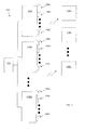
- FIG. 1 depicts an exemplary multi-cell multi-carrier wireless network
- FIG. 2 is a schematic drawing of a controller
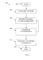
- FIG. 3 is a flowchart of a method of network scheduling according to an embodiment of the present invention.
- FIG. 4 is a flowchart of a method of transmission scheduling according to an embodiment of the present invention.
- FIG. 5 is a flowchart of a method of transmission scheduling according to an embodiment of the present invention.
- FIG. 6 depicts a flowchart of a method 600 of determining maximum additional queue size reduction according to an embodiment of the present invention.
- the present invention is related generally to transmission scheduling, and in particular, to scheduling transmission in multi-cell multi-carrier wireless systems.
- scheduling across multiple cells can be executed. This is advantageous at least because each client (e.g., receiver, user, etc.) may choose the base station with the best signal quality to improve the overall system throughput.
- users are assigned to subcarriers in each base station in order to maximize the overall system throughput. Load balancing and multi-user/multi-channel diversity are exploited to achieve the maximum throughput.
- FIG. 1 depicts an exemplary multi-cell multi-carrier wireless network 100.
- Network 100 includes a controller 102 in communication with a plurality of base stations 104a, 104b, ... , 104M.
- the base stations 104a-104M may transmit signals (e.g., wireless signals) via subcarriers (e.g., in OFDMA systems) 106a-106C to a plurality of receivers 108a, 108b,..., 108N.
- signals e.g., wireless signals
- subcarriers e.g., in OFDMA systems
- Controller 102 is a device adapted to perform the methods 300, 400, 500, and 600 described below with respective reference to FIGS. 3-6 .
- controller 102 is implemented as a controller 200, described below with respect to FIG. 2 .
- Controller may be in communication with base stations 104a-104M via a high speed network.
- network 100 may be an optical wireless integrated network and the conventional components of base stations 104a-104M are located near controller 102.
- Base stations 104a-104M are base stations for transmitting information to mobile stations, as is known.
- Base stations 104a-104M may have and/or be a wireless transmitter (e.g., cellular site, satellite, Tx, etc.) as is known.
- base stations 1 04a-1 04M may each comprise one or more reception antennas (not shown) for receiving input data and/or feedback signals, etc.
- Receivers e.g., users, mobile stations, mobile users, etc.
- 108a-108N may be wireless reception devices (e.g. mobile telephone, ground station, Rx, etc.) as are known and may be capable of receiving signals from base stations 104a-104M and/or sending feedback signals to base stations 104a-104M.
- wireless reception devices e.g. mobile telephone, ground station, Rx, etc.
- FIG. 2 is a schematic drawing of a controller 200 according to an embodiment of the invention.
- Controller 200 may be used as the controller 102 in network 100.
- Controller 200 contains a processor 202 which controls the overall operation of the controller 200 by executing computer program instructions which define such operation.
- the computer program instructions may be stored in a storage device 204 (e.g., magnetic disk, database, etc.) and loaded into memory 206 when execution of the computer program instructions is desired.
- applications for performing the herein-described method steps, such as transmitting data and throughput optimization, in methods 300, 400, 500, and 600 are defined by the computer program instructions stored in the memory 206 and/or storage 204 and controlled by the processor 202 executing the computer program instructions.
- the controller 200 may also include one or more network interfaces 208 for communicating with other devices via a network (e.g., a peer to peer network, etc.).
- the controller 200 also includes input/output devices 210 (e.g., display, keyboard, mouse, speakers, buttons, etc.) that enable user interaction with the controller 200.
- Controller 200 and/or processor 202 may include one or more central processing units, read only memory (ROM) devices and/or random access memory (RAM) devices.
- ROM read only memory
- RAM random access memory
- instructions of a program may be read into memory 206, such as from a ROM device to a RAM device or from a LAN adapter to a RAM device. Execution of sequences of the instructions in the program may cause the controller 200 to perform one or more of the method steps described herein, such as those described below with respect to methods 300, 400, 500, and 600.
- hard-wired circuitry or integrated circuits may be used in place of, or in combination with, software instructions for implementation of the processes of the present invention.
- embodiments of the present invention are not limited to any specific combination of hardware, firmware, and/or software.
- the memory 206 may store the software for the controller 200, which may be adapted to execute the software program and thereby operate in accordance with the present invention and particularly in accordance with the methods described in detail above.
- the invention as described herein could be implemented in many different ways using a wide range of programming techniques as well as general purpose hardware sub-systems or dedicated controllers.
- Such programs may be stored in a compressed, uncompiled and/or encrypted format.
- the programs furthermore may include program elements that may be generally useful, such as an operating system, a database management system, and device drivers for allowing the controller to interface with computer peripheral devices, and other equipment/components.
- Appropriate general purpose program elements are known to those skilled in the art, and need not be described in detail herein.
- FIG. 3 is a flowchart of a method 300 of network transmission according to an embodiment of the present invention.
- Method 300 may be performed (e.g., implemented) by controller 102 and/or base stations 104a-104M of network 100.
- the method 300 starts at step 302.
- step 304 the network is initialized.
- Network 100 is initialized to set up connections and quality of service requirements for each receiver 1 08a-1 08N.
- channel state information is received.
- Channel state information is received from each receiver 108a-108N on each subcarrier 106a-106C in each base station 104a-104M at each frame t.
- the received channel state information includes the achievable rate for each receiver 108a-108N on each subcarrier 106a-106C in each base station 104a-104M.
- only partial channel state information is received. For example, a receiver 108a-108N may only report the data rate on those subcarriers 106a-106C with a rate higher than a certain threshold. Controller 102 may then treat unreported channel gain (e.g., data rate) as zero in the scheduling determination described below with respect to methods 400 and 500.
- unreported channel gain e.g., data rate
- step 308 transmission is scheduled.
- transmission is scheduled by determining subcarrier assignment.
- Controller 102 determines the subcarrier 106a-106C assignment based at least in part on the achievable rate for each receiver 108a-108N on each subcarrier 106a-106C in each base station 104a-104M from step 306.
- controller 102 determines the subcarrier 106a-106C assignment based additionally on a queue size of each receiver 108a-108N.
- step 310 signals are transmitted according to the transmission schedule of step 308. Signals are transmitted from bas stations 104a-104M to receivers 108a-108N via subcarriers 106a-106C.
- the method 300 ends in step 312.
- Subcarrier assignment is discussed in further detail below with respect to methods 400 and 500 of FIGS. 4 and 5 .
- FIG. 4 is a flowchart of a method 400 of transmission scheduling according to an embodiment of the present invention.
- the method 400 may be performed by controller 102 as described above.
- each receiver 108a-108N is served by multiple base stations 104a-104M on different subcarriers 106a-106C.
- the scheduling of method 400 may be used in the determination of subcarrier assignment in step 308 of method 300 above.
- Method 400 may be used in scheduling transmission in a backlogged transmission system. The method begins at step 402.
- step 404 a determination is made as to whether all receivers are assigned. If all receivers 108a-108N are assigned, the method proceeds to step 406 and subcarriers are allocated, as discussed below. If not all of the receivers are assigned, the method proceeds to step 408 and the marginal gain is determined.
- the marginal gain Ag ij is determined for each unassigned receiver j (e.g., of receivers 108a-108N) and each base station I (e.g., of base stations 104a-104M).
- the marginal gain ⁇ g ij may be determined as follows.
- the method 400 then returns control to step 404 and the determination as to whether all receivers are assigned is made again. As before, if all receivers are assigned, the method proceeds to step 406 and subcarriers are allocated. Subcarriers (e.g., subcarriers 106a-106C) are allocated to receivers in each base station by selecting the receiver with the highest gain (e.g., weight multiplied by data rate) among the receivers that have been assigned to the same base station for each subcarrier in each base station.
- gain e.g., weight multiplied by data rate
- the method ends at step 414.
- a fixed receiver is chosen and the best base station is selected to accept the receiver base on the maximum marginal gain ⁇ g ij .
- FIG. 5 is a flowchart of a method 500 of transmission scheduling according to an embodiment of the present invention.
- the method 500 may be performed by controller 102 as described above.
- each receiver 108a-108N is served by multiple base stations 1 04a-1 04M on different subcarriers 106a-106C.
- the scheduling of method 500 may be used in the determination of subcarrier assignment in step 308 of method 300 above.
- Method 500 may be used in scheduling transmission in a transmission system with finite queuing fed by an arrival process. That is, both receiver rates and queue sizes are available to controller 102.
- the method begins at step 502.
- step 504 a determination is made as to whether all receivers are assigned. If all receivers 108a-108N are assigned, the method proceeds to step 506 and the method 500 ends. If not all of the receivers are assigned, the method proceeds to step 508 and the maximum additional queue size reduction is determined.
- the maximum additional queue size reduction ⁇ q ij is determined for each unassigned receiver j and base station i. In at least one embodiment, the maximum additional queue size reduction is determined using dynamic programming, as described below with respect to method 600 of FIG. 6 .
- step 510 the subcarriers assigned to receivers in a base station are recorded. That is, the subcarriers c(i,j) assigned to receiver j in base station i to achieve the additional queue size reduction ⁇ q ij is recorded. In at least one embodiment, this is recorded in a memory (e.g., memory 206 and/or storage 204 in controller 102).
- step 512 the base station and receiver pair that has the maximum additional queue size reduction is determined. That is, the base station/receiver pair (i 0 ,j 0 ) that has the maximum additional queue size reduction ⁇ q ij is determined.
- step 514 the receiver from step 512 is assigned to the base station. That is, the receiver j 0 is assigned to the base station i 0
- step 516 subcarriers are allocated.
- Subcarrier c(i 0 ,j 0 ) e.g., subcarriers 106a-106C
- the method 500 returns control to step 504 and the determination as to whether all receivers are assigned is made again. As before, if all receivers are assigned, the method proceeds to step 506 and ends.
- a fixed receiver is chosen and the best base station that achieves maximum ⁇ q ij is selected to accept the receiver.
- FIG. 6 depicts a flowchart of a method 600 of determining maximum additional queue size reduction according to an embodiment of the present invention.
- Method 600 may be used in determining the maximum additional queue size reduction as in method step 512 of method 500 above. Accordingly, method 600 may be performed by controller 102 of network 100.
- the frame duration is assumed to be one time unit. Otherwise, the data rate may be multiplied on each subcarrier (e.g., subcarriers 106a-106C) by the frame duration.
- the method begins at step 602.
- step 604 the sum of the rates on subcarriers is determined.
- the sum of the rates is calculated on subcarriers for which the receiver j has a higher gain (e.g., weighted data rate).
- step 606 a determination is made as to whether the sum of the rates from step 604 is larger than the total queue size of receiver j. That is, a comparison is made of the sum of the rates from step 604 to the total queue size of receiver j. If the sum of the rates is equal to or smaller than the total queue size of receiver j, this falls to the backlogged traffice model in [0040-0041] and the additional queue size reduction is determined in step 608 as ⁇ q ij as determined above with respect to step 408 of method 400. The method then proceeds to step 622 and ends. If the sum of the rates is larger than the total queue size of receiver j, the method proceeds to step 610 and a minimum queue size required to achieve additional queue size reduction p is determined.
- Q k (p) is the minimum queue size used to have additional queue size reduction p using the first k subcarriers.
- Q k (p) is determined using dynamic programming.
- step 612 the maximum additional weighted queue size reduction is determined.
- bit allocations are determined.
- the bit allocations on each subcarrier k may be found using traditional backtracking or any other equivalent method.
- step 616 a determination is made as to whether the last subcarrier is the only partially allocated subcarrier. If the last subcarrier is the only partially allocated subcarrier the method proceeds to step 618 and the determined maximum weighted sum of queue size reduction for each receiver is output. In at least one embodiment, the determined maximum weighted sum of queue size reduction for each receiver is output to controller 102 (e.g., for use in method 500 above). The method ends at step 622.
- step 620 the allocation is drifted from the last subcarrier allocated to receiver j to the first allocated subcarrier to make the last subcarrier the only partially allocated subcarrier. In this way, it is not necessary to try all possible subcarriers as the last partially allocated subcarrier.
- the recursive equation may be started backwards resulting in the only partially allocated subcarrier being the last allocated subcarrier.
- step 618 the determined maximum weighted sum of queue size reduction for each receiver is output.
- the weighted sum of the data rates on all subcarriers is determined. If it is less than the queue size of receiver j, the optimal solution is the weighted sum of the data rate increase due to receiver j, which is ⁇ g ij , as described above with respect to step 408 of method 400.
- transmission is scheduled in a multi-cell multi carrier wireless network.
- Assignments are determined for subcarriers by determining marginal gains for receivers, determining a receiver and an associated base station corresponding to a highest marginal gain, and assigning the receiver to the base station. These steps may be iteratively repeated until each of the receivers is assigned to a base station. The subcarriers are then allocated to the receivers by selecting the receiver with the highest gain. Alternatively, assignments are determined for subcarriers by determining a maximum additional queue size reduction, determining an assignment for each of the subcarriers, determining a receiver associated with a base station that has the determined maximum additional queue size reduction, assigning the receiver to the base station, and allocating the subcarriers to the receivers in the base stations.
Landscapes
- Engineering & Computer Science (AREA)
- Signal Processing (AREA)
- Computer Networks & Wireless Communication (AREA)
- Quality & Reliability (AREA)
- Mobile Radio Communication Systems (AREA)
Abstract
Description
- This application claims the benefit of
U.S. Provisional Application No. 61/035,752 filed on March 12, 2008 - The present invention is related generally to transmission scheduling, and in particular, to scheduling transmission in multi-cell multi-carrier wireless systems.
- Scheduling problems in cellular networks arise from excessive loading in the networks, delaying transmissions. Proportional fairness scheduling algorithms have been used. At every slot, the user is served with the largest ratio of the instantaneous service rate to its average service rate.
- In Orthogonal Frequency-Division Multiple Access (OFDMA) based multi-carrier systems, scheduling improvements are needed to avoid multi-path interference and to achieve higher spectral efficiency. However, conventional solutions only address scheduling in single-cell networks and do not consider the effect of finite queue size of each user.
- Additionally, in conventional scheduling, it was believed that scheduling across multiple cells was not practical due to the large latency and large overhead between base stations and the radio network controller. For this reason, scheduling in multi-cell multi-carrier wireless systems was ignored.
- Therefore, there remains a need to improve throughput in multi-cell multi-carrier wireless networks.
- In one embodiment of the present invention, a method for transmission in a multi-cell multi-carrier wireless network includes receiving channel state information, determining assignments for a plurality of subcarriers based at least in part on the received channel state information, scheduling transmission based on the subcarrier assignment, and transmitting information based on the scheduled transmission.
- In one embodiment of the present invention, assignments are determined for a plurality of subcarriers by determining marginal gains for a plurality of receivers, determining a receiver and an associated base station in a plurality of base stations corresponding to a highest marginal gain, and assigning the determined receiver to the determined base station. These steps may be iteratively repeated until each of the plurality of receivers is assigned to an associated base station. The plurality of subcarriers are then allocated to the plurality of receivers by selecting the receiver with the highest gain among the plurality of receivers assigned to the associated base station for each subcarrier in each base station.
- In one embodiment of the present invention, the assignments are determined for a plurality of subcarriers by determining a maximum additional queue size reduction, determining an assignment for each of the plurality of subcarriers based on the determined maximum additional queue size reduction, recording the determined assignments for each of the plurality of subcarriers, determining a receiver from a plurality of receivers associated with a base station from a plurality of base stations that has the determined maximum additional queue size reduction, assigning the receiver from the plurality of receivers to the base station from the plurality of base stations, and allocating the plurality of subcarriers to the plurality of receivers in the plurality of base stations.
- The maximum additional queue size reduction is determined by determining a sum of rates for each of the plurality of subcarriers, determining a minimum queue size, determining the maximum additional queue size reduction based at least in part on the determined minimum queue size, and determining a bit allocation for each of the plurality of subcarriers.
- These and other advantages of the invention will be apparent to those of ordinary skill in the art by reference to the following detailed description and the accompanying drawings.
-
FIG. 1 depicts an exemplary multi-cell multi-carrier wireless network; -
FIG. 2 is a schematic drawing of a controller; -
FIG. 3 is a flowchart of a method of network scheduling according to an embodiment of the present invention; -
FIG. 4 is a flowchart of a method of transmission scheduling according to an embodiment of the present invention; -
FIG. 5 is a flowchart of a method of transmission scheduling according to an embodiment of the present invention; and -
FIG. 6 depicts a flowchart of amethod 600 of determining maximum additional queue size reduction according to an embodiment of the present invention. - The present invention is related generally to transmission scheduling, and in particular, to scheduling transmission in multi-cell multi-carrier wireless systems. With the advance of passive optical networks and optical wireless integration, scheduling across multiple cells can be executed. This is advantageous at least because each client (e.g., receiver, user, etc.) may choose the base station with the best signal quality to improve the overall system throughput.
- In at least one embodiment of the present invention, users are assigned to subcarriers in each base station in order to maximize the overall system throughput. Load balancing and multi-user/multi-channel diversity are exploited to achieve the maximum throughput.
-
FIG. 1 depicts an exemplary multi-cell multi-carrierwireless network 100. Network 100 includes acontroller 102 in communication with a plurality ofbase stations base stations 104a-104M may transmit signals (e.g., wireless signals) via subcarriers (e.g., in OFDMA systems) 106a-106C to a plurality ofreceivers -
Controller 102 is a device adapted to perform themethods FIGS. 3-6 . In at least one embodiment,controller 102 is implemented as acontroller 200, described below with respect toFIG. 2 . - Controller may be in communication with
base stations 104a-104M via a high speed network. In at least one embodiment,network 100 may be an optical wireless integrated network and the conventional components ofbase stations 104a-104M are located nearcontroller 102. -
Base stations 104a-104M are base stations for transmitting information to mobile stations, as is known.Base stations 104a-104M may have and/or be a wireless transmitter (e.g., cellular site, satellite, Tx, etc.) as is known. Further, base stations 1 04a-1 04M may each comprise one or more reception antennas (not shown) for receiving input data and/or feedback signals, etc. - Receivers (e.g., users, mobile stations, mobile users, etc.) 108a-108N may be wireless reception devices (e.g. mobile telephone, ground station, Rx, etc.) as are known and may be capable of receiving signals from
base stations 104a-104M and/or sending feedback signals tobase stations 104a-104M. -
FIG. 2 is a schematic drawing of acontroller 200 according to an embodiment of the invention.Controller 200 may be used as thecontroller 102 innetwork 100.Controller 200 contains aprocessor 202 which controls the overall operation of thecontroller 200 by executing computer program instructions which define such operation. The computer program instructions may be stored in a storage device 204 (e.g., magnetic disk, database, etc.) and loaded intomemory 206 when execution of the computer program instructions is desired. Thus, applications for performing the herein-described method steps, such as transmitting data and throughput optimization, inmethods memory 206 and/orstorage 204 and controlled by theprocessor 202 executing the computer program instructions. Thecontroller 200 may also include one ormore network interfaces 208 for communicating with other devices via a network (e.g., a peer to peer network, etc.). Thecontroller 200 also includes input/output devices 210 (e.g., display, keyboard, mouse, speakers, buttons, etc.) that enable user interaction with thecontroller 200.Controller 200 and/orprocessor 202 may include one or more central processing units, read only memory (ROM) devices and/or random access memory (RAM) devices. One skilled in the art will recognize that an implementation of an actual controller could contain other components as well, and that the controller ofFIG. 2 is a high level representation of some of the components of such a controller for illustrative purposes. - According to some embodiments of the present invention, instructions of a program (e.g., controller software) may be read into
memory 206, such as from a ROM device to a RAM device or from a LAN adapter to a RAM device. Execution of sequences of the instructions in the program may cause thecontroller 200 to perform one or more of the method steps described herein, such as those described below with respect tomethods memory 206 may store the software for thecontroller 200, which may be adapted to execute the software program and thereby operate in accordance with the present invention and particularly in accordance with the methods described in detail above. However, it would be understood by one of ordinary skill in the art that the invention as described herein could be implemented in many different ways using a wide range of programming techniques as well as general purpose hardware sub-systems or dedicated controllers. - Such programs may be stored in a compressed, uncompiled and/or encrypted format. The programs furthermore may include program elements that may be generally useful, such as an operating system, a database management system, and device drivers for allowing the controller to interface with computer peripheral devices, and other equipment/components. Appropriate general purpose program elements are known to those skilled in the art, and need not be described in detail herein.
-
FIG. 3 is a flowchart of amethod 300 of network transmission according to an embodiment of the present invention.Method 300 may be performed (e.g., implemented) bycontroller 102 and/orbase stations 104a-104M ofnetwork 100. Themethod 300 starts atstep 302. - In
step 304, the network is initialized.Network 100 is initialized to set up connections and quality of service requirements for each receiver 1 08a-1 08N. - In
step 306, channel state information is received. Channel state information is received from eachreceiver 108a-108N on eachsubcarrier 106a-106C in eachbase station 104a-104M at each frame t. The received channel state information includes the achievable rate for eachreceiver 108a-108N on eachsubcarrier 106a-106C in eachbase station 104a-104M. In at least one embodiment, only partial channel state information is received. For example, areceiver 108a-108N may only report the data rate on thosesubcarriers 106a-106C with a rate higher than a certain threshold.Controller 102 may then treat unreported channel gain (e.g., data rate) as zero in the scheduling determination described below with respect tomethods - In
step 308, transmission is scheduled. In at least one embodiment, transmission is scheduled by determining subcarrier assignment.Controller 102 determines thesubcarrier 106a-106C assignment based at least in part on the achievable rate for eachreceiver 108a-108N on eachsubcarrier 106a-106C in eachbase station 104a-104M fromstep 306. In at least one embodiment,controller 102 determines thesubcarrier 106a-106C assignment based additionally on a queue size of eachreceiver 108a-108N. - In
step 310, signals are transmitted according to the transmission schedule ofstep 308. Signals are transmitted frombas stations 104a-104M toreceivers 108a-108N viasubcarriers 106a-106C. - In at least one embodiment, the
method 300 returns control to step 306 and further channel state information is received. That is, the frame is incremented (t=t+1) and themethod 300 repeats iteratively. - The
method 300 ends instep 312. - Subcarrier assignment is discussed in further detail below with respect to
methods FIGS. 4 and5 . -
FIG. 4 is a flowchart of amethod 400 of transmission scheduling according to an embodiment of the present invention. Themethod 400 may be performed bycontroller 102 as described above. Inmethod 400, eachreceiver 108a-108N is served bymultiple base stations 104a-104M ondifferent subcarriers 106a-106C. In at least one embodiment, the scheduling ofmethod 400 may be used in the determination of subcarrier assignment instep 308 ofmethod 300 above.Method 400 may be used in scheduling transmission in a backlogged transmission system. The method begins atstep 402. - In
step 404, a determination is made as to whether all receivers are assigned. If allreceivers 108a-108N are assigned, the method proceeds to step 406 and subcarriers are allocated, as discussed below. If not all of the receivers are assigned, the method proceeds to step 408 and the marginal gain is determined. - The marginal gain Ag ij is determined for each unassigned receiver j (e.g., of
receivers 108a-108N) and each base station I (e.g., ofbase stations 104a-104M). The marginal gain Δgij may be determined as follows. - If the gain of each receiver j on subcarrier c in base station I is aijc = wijcrijc and Si is the set of receivers assigned to base station j,

- In
step 410, the base station and receiver pair with the highest marginal gain is determined. Based on this determination, the receiver is assigned to the base station instep 412. That is, receiver j0 is assigned to the base station i0. That is, S i0 = S i0 ∪ {j 0}, U = U - (j 0} where U is the set of unassigned receivers. - The
method 400 then returns control to step 404 and the determination as to whether all receivers are assigned is made again. As before, if all receivers are assigned, the method proceeds to step 406 and subcarriers are allocated. Subcarriers (e.g.,subcarriers 106a-106C) are allocated to receivers in each base station by selecting the receiver with the highest gain (e.g., weight multiplied by data rate) among the receivers that have been assigned to the same base station for each subcarrier in each base station. - After allocation of subcarriers in
step 406, the method ends atstep 414. In an alternative embodiment, at each of method steps 408 to 412, a fixed receiver is chosen and the best base station is selected to accept the receiver base on the maximum marginal gain Δgij . -
FIG. 5 is a flowchart of amethod 500 of transmission scheduling according to an embodiment of the present invention. Themethod 500 may be performed bycontroller 102 as described above. Inmethod 500, eachreceiver 108a-108N is served by multiple base stations 1 04a-1 04M ondifferent subcarriers 106a-106C. In at least one embodiment, the scheduling ofmethod 500 may be used in the determination of subcarrier assignment instep 308 ofmethod 300 above.Method 500 may be used in scheduling transmission in a transmission system with finite queuing fed by an arrival process. That is, both receiver rates and queue sizes are available tocontroller 102. The method begins atstep 502. - In
step 504, a determination is made as to whether all receivers are assigned. If allreceivers 108a-108N are assigned, the method proceeds to step 506 and themethod 500 ends. If not all of the receivers are assigned, the method proceeds to step 508 and the maximum additional queue size reduction is determined. - The maximum additional queue size reduction Δqij is determined for each unassigned receiver j and base station i. In at least one embodiment, the maximum additional queue size reduction is determined using dynamic programming, as described below with respect to
method 600 ofFIG. 6 . - In
step 510, the subcarriers assigned to receivers in a base station are recorded. That is, the subcarriers c(i,j) assigned to receiver j in base station i to achieve the additional queue size reduction Δqij is recorded. In at least one embodiment, this is recorded in a memory (e.g.,memory 206 and/orstorage 204 in controller 102). - In
step 512, the base station and receiver pair that has the maximum additional queue size reduction is determined. That is, the base station/receiver pair (i0,j0) that has the maximum additional queue size reduction Δqij is determined. - In
step 514, the receiver fromstep 512 is assigned to the base station. That is, the receiver j0 is assigned to the base station i0 - In
step 516, subcarriers are allocated. Subcarrier c(i0,j0) (e.g.,subcarriers 106a-106C) is allocated in base station i0 to receiver j0. All previous allocations to the subcarriers are removed. Following subcarrier allocation instep 516, themethod 500 returns control to step 504 and the determination as to whether all receivers are assigned is made again. As before, if all receivers are assigned, the method proceeds to step 506 and ends. - In an alternative embodiment, for method steps 508-516, a fixed receiver is chosen and the best base station that achieves maximum Δqij is selected to accept the receiver.
-
FIG. 6 depicts a flowchart of amethod 600 of determining maximum additional queue size reduction according to an embodiment of the present invention.Method 600 may be used in determining the maximum additional queue size reduction as inmethod step 512 ofmethod 500 above. Accordingly,method 600 may be performed bycontroller 102 ofnetwork 100. - Without loss of generality, the frame duration is assumed to be one time unit. Otherwise, the data rate may be multiplied on each subcarrier (e.g.,
subcarriers 106a-106C) by the frame duration. The method begins atstep 602. -
Method 600 is used to determine the maximum additional queue size reduction as max Σ max(0,wjuijc -vic ) such that uijc ≤ rijc for any c and Σ uijc ≤ qj where wj is the weight of the receiver j, vic is the current weighted reduction on subcarrier c, qj is the queue size of receiver j, and uijc is a variable. This may be expressed as max Σ max (0, uijc - v ' ic ) where v ' ic = vic / wj . - In
step 604, the sum of the rates on subcarriers is determined. The sum of the rates is calculated on subcarriers for which the receiver j has a higher gain (e.g., weighted data rate). - In
step 606, a determination is made as to whether the sum of the rates fromstep 604 is larger than the total queue size of receiver j. That is, a comparison is made of the sum of the rates fromstep 604 to the total queue size of receiver j. If the sum of the rates is equal to or smaller than the total queue size of receiver j, this falls to the backlogged traffice model in [0040-0041] and the additional queue size reduction is determined instep 608 as Δqij as determined above with respect to step 408 ofmethod 400. The method then proceeds to step 622 and ends. If the sum of the rates is larger than the total queue size of receiver j, the method proceeds to step 610 and a minimum queue size required to achieve additional queue size reduction p is determined. - Qk(p) is the minimum queue size used to have additional queue size reduction p using the first k subcarriers. Qk(p) is initially


Based on the initial conditions and recursive equations, Qk(p) is determined using dynamic programming. - In
step 612, the maximum additional weighted queue size reduction is determined. The maximum value p is determined such that Qk(p) ≤ qj where qj is the queue size of receiver j.Steps - In
step 614, bit allocations are determined. The bit allocations on each subcarrier k may be found using traditional backtracking or any other equivalent method. - In
step 616, a determination is made as to whether the last subcarrier is the only partially allocated subcarrier. If the last subcarrier is the only partially allocated subcarrier the method proceeds to step 618 and the determined maximum weighted sum of queue size reduction for each receiver is output. In at least one embodiment, the determined maximum weighted sum of queue size reduction for each receiver is output to controller 102 (e.g., for use inmethod 500 above). The method ends at step 622. - If the last subcarrier is not the only partially allocated subcarrier the method proceeds to step 620 and the allocation is drifted from the last subcarrier allocated to receiver j to the first allocated subcarrier to make the last subcarrier the only partially allocated subcarrier. In this way, it is not necessary to try all possible subcarriers as the last partially allocated subcarrier. Alternatively, the recursive equation may be started backwards resulting in the only partially allocated subcarrier being the last allocated subcarrier.
- The method then proceeds to step 618 and the determined maximum weighted sum of queue size reduction for each receiver is output.
- In an alternative embodiment, prior to dynamic programming in
step 610, the weighted sum of the data rates on all subcarriers, where the data rate for receiver j is larger than the current allocation, is determined. If it is less than the queue size of receiver j, the optimal solution is the weighted sum of the data rate increase due to receiver j, which is Δgij , as described above with respect to step 408 ofmethod 400. - The foregoing Detailed Description is to be understood as being in every respect illustrative and exemplary, but not restrictive, and the scope of the invention disclosed herein is not to be determined from the Detailed Description, but rather from the claims as interpreted according to the full breadth permitted by the patent laws. It is to be understood that the embodiments shown and described herein are only illustrative of the principles of the present invention and that various modifications may be implemented by those skilled in the art without departing from the scope and spirit of the invention. Those skilled in the art could implement various other feature combinations without departing from the scope and spirit of the invention.
According to one embodiment transmission is scheduled in a multi-cell multi carrier wireless network. Assignments are determined for subcarriers by determining marginal gains for receivers, determining a receiver and an associated base station corresponding to a highest marginal gain, and assigning the receiver to the base station. These steps may be iteratively repeated until each of the receivers is assigned to a base station. The subcarriers are then allocated to the receivers by selecting the receiver with the highest gain. Alternatively, assignments are determined for subcarriers by determining a maximum additional queue size reduction, determining an assignment for each of the subcarriers, determining a receiver associated with a base station that has the determined maximum additional queue size reduction, assigning the receiver to the base station, and allocating the subcarriers to the receivers in the base stations.
Claims (14)
- A method for transmission in a multi-cell multi-carrier wireless network comprising:receiving channel state information;determining assignments for a plurality of subcarriers based at least in part on the received channel state information; andscheduling transmission based on the subcarrier assignment.
- The method of claim 1 further comprising:transmitting information based on the scheduled transmission.
- The method of claim 1 or 2 wherein determining assignments for the plurality of subcarriers comprises:(a) determining marginal gains for a plurality of receivers;(b) determining a receiver and an associated base station in a plurality of base stations corresponding to a highest marginal gain; and(c) assigning the determined receiver to the determined base station.
- The method of claim 3 further comprising:iteratively repeating steps a to c until each of the plurality of receivers is assigned to an associated base station; andallocating the plurality of subcarriers to the plurality of receivers by selecting the receiver with the highest gain among the plurality of receivers assigned to the associated base station for each subcarrier in each base station.
- The method of claim 3 or 4, wherein determining marginal gains for a plurality of receivers comprises determining Δgij = Σ max(0, aijc - maxaikc ) where Δgij is the marginal gain, j is the plurality of receivers, i is the plurality of base stations, and c is the plurality of subcarriers associated with the plurality of base stations i.
- The method of one of the preceding claims, wherein determining assignments for the plurality of subcarriers comprises:determining a maximum additional queue size reduction;determining an assignment for each of the plurality of subcarriers based on the determined maximum additional queue size reduction;recording the determined assignments for each of the plurality of subcarriers;determining a receiver from a plurality of receivers associated with a base station from a plurality of base stations that has the determined maximum additional queue size reduction;assigning the receiver from the plurality of receivers to the base station from the plurality of base stations; andallocating the plurality of subcarriers to the plurality of receivers in the plurality of base stations.
- The method of claim 6 wherein determining a maximum additional queue size reduction comprises:determining a sum of rates for each of the plurality of subcarriers;determining a minimum queue size to achieve each additional queue size reduction p;determining the maximum additional queue size reduction based at least in part on the determined minimum queue size; anddetermining a bit allocation for each of the plurality of subcarriers.
- The method of claim 7 wherein determining a minimum queue size comprises determining the minimum queue size using dynamic programming.
- The method of claim 7 or 8 further comprising:determining if a last subcarrier of the plurality of subcarriers is the only partially allocated subcarrier; anddrifting an allocation of the last subcarrier to a first subcarrier of the plurality of subcarriers if the last subcarrier of the plurality of subcarriers is not the only partially allocated subcarrier.
- The method of one of claims 1 to 9, wherein determining assignments for the plurality of subcarriers comprises:a) determining marginal gains for a plurality of receivers;b) assigning receivers to respectively associated base stations based on said determined marginal gains.
- The method of claim 1, further comprising:any individual additional feature or any combination of the features as additionally defined in one of claims 2 to 10.
- A computer readable medium having program instructions stored thereon, the instructions capable of execution by a processor and defining the steps of:receiving channel state information;determining assignments for a plurality of subcarriers based at least in part on the received channel state information; andscheduling transmission based on the subcarrier assignment.
- The computer readable medium of claim 10 wherein the instructions further define the steps of the method as defined in one of claims 2 to 11.
- Computer program comprising computer program code which when being executed on a computer enables said computer to carry out a method according to one of claims 1 to 11.
Applications Claiming Priority (2)
| Application Number | Priority Date | Filing Date | Title |
|---|---|---|---|
| US3575208P | 2008-03-12 | 2008-03-12 | |
| US12/237,993 US8023455B2 (en) | 2008-03-12 | 2008-09-25 | Scheduling in multi-cell multi-carrier wireless systems |
Publications (3)
| Publication Number | Publication Date |
|---|---|
| EP2101460A2 true EP2101460A2 (en) | 2009-09-16 |
| EP2101460A3 EP2101460A3 (en) | 2014-12-31 |
| EP2101460B1 EP2101460B1 (en) | 2016-08-31 |
Family
ID=40793110
Family Applications (1)
| Application Number | Title | Priority Date | Filing Date |
|---|---|---|---|
| EP09152679.8A Not-in-force EP2101460B1 (en) | 2008-03-12 | 2009-02-12 | Scheduling in multi-cell multi-carrier wireless systems |
Country Status (2)
| Country | Link |
|---|---|
| US (1) | US8023455B2 (en) |
| EP (1) | EP2101460B1 (en) |
Cited By (1)
| Publication number | Priority date | Publication date | Assignee | Title |
|---|---|---|---|---|
| CN102098737A (en) * | 2009-12-11 | 2011-06-15 | 中兴通讯股份有限公司 | Cell priority level based cooperation scheduling method and system |
Families Citing this family (2)
| Publication number | Priority date | Publication date | Assignee | Title |
|---|---|---|---|---|
| US10932284B2 (en) * | 2016-02-02 | 2021-02-23 | Ethertronics, Inc. | Adaptive antenna for channel selection management in communications systems |
| CN118714586A (en) * | 2017-09-13 | 2024-09-27 | 伊索电子股份有限公司 | Method and system for configuring access points within a communication network |
Family Cites Families (7)
| Publication number | Priority date | Publication date | Assignee | Title |
|---|---|---|---|---|
| US7321614B2 (en) * | 2003-08-08 | 2008-01-22 | Intel Corporation | Apparatus and methods for communicating using symbol-modulated subcarriers |
| KR100943624B1 (en) * | 2003-09-15 | 2010-02-24 | 삼성전자주식회사 | Dynamic Resource Allocation Device and Method in Orthogonal Frequency Division Multiple Communication System |
| WO2005081439A1 (en) * | 2004-02-13 | 2005-09-01 | Neocific, Inc. | Methods and apparatus for multi-carrier communication systems with adaptive transmission and feedback |
| KR100663548B1 (en) * | 2004-08-28 | 2007-01-02 | 삼성전자주식회사 | Apparatus and Method for Subcarrier Allocation in Orthogonal Frequency Division Multiple Access Communication System |
| US7602837B2 (en) * | 2005-10-20 | 2009-10-13 | Freescale Semiconductor, Inc. | Beamforming for non-collaborative, space division multiple access systems |
| EP2375585B1 (en) * | 2006-10-31 | 2018-10-10 | Qualcomm Incorporated | Unified design and centralized scheduling for dynamic Simo, SU-Mimo and MU-Mimo operation for RL transmissions |
| US8121211B2 (en) * | 2007-03-26 | 2012-02-21 | Cisco Technology, Inc. | Adaptive switching techniques for hybrid automatic repeat request systems |
-
2008
- 2008-09-25 US US12/237,993 patent/US8023455B2/en active Active
-
2009
- 2009-02-12 EP EP09152679.8A patent/EP2101460B1/en not_active Not-in-force
Cited By (4)
| Publication number | Priority date | Publication date | Assignee | Title |
|---|---|---|---|---|
| CN102098737A (en) * | 2009-12-11 | 2011-06-15 | 中兴通讯股份有限公司 | Cell priority level based cooperation scheduling method and system |
| WO2011069468A1 (en) * | 2009-12-11 | 2011-06-16 | 中兴通讯股份有限公司 | Method and system for coordinated scheduling based on cell priority |
| CN102098737B (en) * | 2009-12-11 | 2014-02-26 | 中兴通讯股份有限公司 | Cell priority level based cooperation scheduling method and system |
| US9288817B2 (en) | 2009-12-11 | 2016-03-15 | Zte Corporation | Method and system for coordinated scheduling based on cell priority |
Also Published As
| Publication number | Publication date |
|---|---|
| US20090232064A1 (en) | 2009-09-17 |
| EP2101460B1 (en) | 2016-08-31 |
| US8023455B2 (en) | 2011-09-20 |
| EP2101460A3 (en) | 2014-12-31 |
Similar Documents
| Publication | Publication Date | Title |
|---|---|---|
| US9474082B2 (en) | Method and apparatus for co-scheduling transmissions in a wireless network | |
| KR101319795B1 (en) | Operation method of access point and wireless communication system using access point | |
| CN100589474C (en) | A cross-layer scheduling method in OFDM multi-antenna system | |
| EP2244513A1 (en) | Multi-carrier communication base station device and sub carrier allocation method | |
| Li et al. | Joint mode selection and resource allocation for D2D communications under queueing constraints | |
| EP2101460B1 (en) | Scheduling in multi-cell multi-carrier wireless systems | |
| KR20150002316A (en) | Wireless communication apparatus and method of operating the same | |
| KR20080004161A (en) | Apparatus and Method for Radio Resource Allocation in Adaptive Antenna System | |
| US20090002235A1 (en) | Radio Communication System, Transmission Apparatus, Transmission Method, Program and Recording Medium | |
| JP6325170B2 (en) | Method and system for transmitting information from a transmitter to a receiver across a MIMO channel | |
| KR100922959B1 (en) | Resource scheduling apparatus and method in a multi-antenna system | |
| CN113286373A (en) | Uplink multi-user-multi-input multi-output scheduling method and device | |
| KR20200072213A (en) | Noma system and its method for scheduling multi-user | |
| CN101772164B (en) | Method and device for allocating time-frequency resource sending detection signal in base station | |
| CN109787666B (en) | A frequency domain scheduling method, device and equipment | |
| US7852953B2 (en) | Method for allocation of power in multiuser orthogonal frequency division multiplexing | |
| CN116318289B (en) | Space-time-frequency three-dimensional resource allocation method for MU-MIMO system | |
| CN113382475B (en) | Resource scheduling method and device based on MUMIMO | |
| CN103166692A (en) | Receiving device and transmitting device | |
| KR101730730B1 (en) | OFDM System and Method for power allocation using the same | |
| KR20130070847A (en) | Appratus and method for trnasmiting signal in an wireless communication systems | |
| JP2007159153A (en) | Wireless communication system and wireless access method | |
| HK1177374B (en) | An improved method and apparatus for co-scheduling transmissions in a wireless network |
Legal Events
| Date | Code | Title | Description |
|---|---|---|---|
| PUAI | Public reference made under article 153(3) epc to a published international application that has entered the european phase |
Free format text: ORIGINAL CODE: 0009012 |
|
| AK | Designated contracting states |
Kind code of ref document: A2 Designated state(s): AT BE BG CH CY CZ DE DK EE ES FI FR GB GR HR HU IE IS IT LI LT LU LV MC MK MT NL NO PL PT RO SE SI SK TR |
|
| AX | Request for extension of the european patent |
Extension state: AL BA RS |
|
| PUAL | Search report despatched |
Free format text: ORIGINAL CODE: 0009013 |
|
| RIC1 | Information provided on ipc code assigned before grant |
Ipc: H04L 5/00 20060101ALI20141119BHEP Ipc: H04W 16/10 20090101ALI20141119BHEP Ipc: H04L 27/26 20060101AFI20141119BHEP Ipc: H04W 36/30 20090101ALI20141119BHEP Ipc: H04W 72/08 20090101ALI20141119BHEP Ipc: H04W 72/04 20090101ALI20141119BHEP |
|
| AK | Designated contracting states |
Kind code of ref document: A3 Designated state(s): AT BE BG CH CY CZ DE DK EE ES FI FR GB GR HR HU IE IS IT LI LT LU LV MC MK MT NL NO PL PT RO SE SI SK TR |
|
| AX | Request for extension of the european patent |
Extension state: AL BA RS |
|
| 17P | Request for examination filed |
Effective date: 20150630 |
|
| RBV | Designated contracting states (corrected) |
Designated state(s): AT BE BG CH CY CZ DE DK EE ES FI FR GB GR HR HU IE IS IT LI LT LU LV MC MK MT NL NO PL PT RO SE SI SK TR |
|
| AKX | Designation fees paid |
Designated state(s): AT BE BG CH CY CZ DE DK EE ES FI FR GB GR HR HU IE IS IT LI LT LU LV MC MK MT NL NO PL PT RO SE SI SK TR |
|
| AXX | Extension fees paid |
Extension state: BA Extension state: AL Extension state: RS |
|
| 17Q | First examination report despatched |
Effective date: 20150918 |
|
| GRAP | Despatch of communication of intention to grant a patent |
Free format text: ORIGINAL CODE: EPIDOSNIGR1 |
|
| INTG | Intention to grant announced |
Effective date: 20160314 |
|
| GRAS | Grant fee paid |
Free format text: ORIGINAL CODE: EPIDOSNIGR3 |
|
| RAP1 | Party data changed (applicant data changed or rights of an application transferred) |
Owner name: NEC CORPORATION |
|
| GRAA | (expected) grant |
Free format text: ORIGINAL CODE: 0009210 |
|
| AK | Designated contracting states |
Kind code of ref document: B1 Designated state(s): AT BE BG CH CY CZ DE DK EE ES FI FR GB GR HR HU IE IS IT LI LT LU LV MC MK MT NL NO PL PT RO SE SI SK TR |
|
| REG | Reference to a national code |
Ref country code: CH Ref legal event code: EP Ref country code: GB Ref legal event code: FG4D |
|
| REG | Reference to a national code |
Ref country code: IE Ref legal event code: FG4D |
|
| REG | Reference to a national code |
Ref country code: DE Ref legal event code: R096 Ref document number: 602009040730 Country of ref document: DE |
|
| REG | Reference to a national code |
Ref country code: AT Ref legal event code: REF Ref document number: 825832 Country of ref document: AT Kind code of ref document: T Effective date: 20161015 |
|
| REG | Reference to a national code |
Ref country code: LT Ref legal event code: MG4D |
|
| REG | Reference to a national code |
Ref country code: NL Ref legal event code: MP Effective date: 20160831 |
|
| REG | Reference to a national code |
Ref country code: AT Ref legal event code: MK05 Ref document number: 825832 Country of ref document: AT Kind code of ref document: T Effective date: 20160831 |
|
| PG25 | Lapsed in a contracting state [announced via postgrant information from national office to epo] |
Ref country code: HR Free format text: LAPSE BECAUSE OF FAILURE TO SUBMIT A TRANSLATION OF THE DESCRIPTION OR TO PAY THE FEE WITHIN THE PRESCRIBED TIME-LIMIT Effective date: 20160831 Ref country code: LT Free format text: LAPSE BECAUSE OF FAILURE TO SUBMIT A TRANSLATION OF THE DESCRIPTION OR TO PAY THE FEE WITHIN THE PRESCRIBED TIME-LIMIT Effective date: 20160831 Ref country code: FI Free format text: LAPSE BECAUSE OF FAILURE TO SUBMIT A TRANSLATION OF THE DESCRIPTION OR TO PAY THE FEE WITHIN THE PRESCRIBED TIME-LIMIT Effective date: 20160831 Ref country code: NO Free format text: LAPSE BECAUSE OF FAILURE TO SUBMIT A TRANSLATION OF THE DESCRIPTION OR TO PAY THE FEE WITHIN THE PRESCRIBED TIME-LIMIT Effective date: 20161130 |
|
| PG25 | Lapsed in a contracting state [announced via postgrant information from national office to epo] |
Ref country code: GR Free format text: LAPSE BECAUSE OF FAILURE TO SUBMIT A TRANSLATION OF THE DESCRIPTION OR TO PAY THE FEE WITHIN THE PRESCRIBED TIME-LIMIT Effective date: 20161201 Ref country code: NL Free format text: LAPSE BECAUSE OF FAILURE TO SUBMIT A TRANSLATION OF THE DESCRIPTION OR TO PAY THE FEE WITHIN THE PRESCRIBED TIME-LIMIT Effective date: 20160831 Ref country code: ES Free format text: LAPSE BECAUSE OF FAILURE TO SUBMIT A TRANSLATION OF THE DESCRIPTION OR TO PAY THE FEE WITHIN THE PRESCRIBED TIME-LIMIT Effective date: 20160831 Ref country code: SE Free format text: LAPSE BECAUSE OF FAILURE TO SUBMIT A TRANSLATION OF THE DESCRIPTION OR TO PAY THE FEE WITHIN THE PRESCRIBED TIME-LIMIT Effective date: 20160831 Ref country code: LV Free format text: LAPSE BECAUSE OF FAILURE TO SUBMIT A TRANSLATION OF THE DESCRIPTION OR TO PAY THE FEE WITHIN THE PRESCRIBED TIME-LIMIT Effective date: 20160831 Ref country code: AT Free format text: LAPSE BECAUSE OF FAILURE TO SUBMIT A TRANSLATION OF THE DESCRIPTION OR TO PAY THE FEE WITHIN THE PRESCRIBED TIME-LIMIT Effective date: 20160831 |
|
| REG | Reference to a national code |
Ref country code: FR Ref legal event code: PLFP Year of fee payment: 9 |
|
| PG25 | Lapsed in a contracting state [announced via postgrant information from national office to epo] |
Ref country code: RO Free format text: LAPSE BECAUSE OF FAILURE TO SUBMIT A TRANSLATION OF THE DESCRIPTION OR TO PAY THE FEE WITHIN THE PRESCRIBED TIME-LIMIT Effective date: 20160831 Ref country code: EE Free format text: LAPSE BECAUSE OF FAILURE TO SUBMIT A TRANSLATION OF THE DESCRIPTION OR TO PAY THE FEE WITHIN THE PRESCRIBED TIME-LIMIT Effective date: 20160831 |
|
| PG25 | Lapsed in a contracting state [announced via postgrant information from national office to epo] |
Ref country code: BG Free format text: LAPSE BECAUSE OF FAILURE TO SUBMIT A TRANSLATION OF THE DESCRIPTION OR TO PAY THE FEE WITHIN THE PRESCRIBED TIME-LIMIT Effective date: 20161130 Ref country code: SK Free format text: LAPSE BECAUSE OF FAILURE TO SUBMIT A TRANSLATION OF THE DESCRIPTION OR TO PAY THE FEE WITHIN THE PRESCRIBED TIME-LIMIT Effective date: 20160831 Ref country code: CZ Free format text: LAPSE BECAUSE OF FAILURE TO SUBMIT A TRANSLATION OF THE DESCRIPTION OR TO PAY THE FEE WITHIN THE PRESCRIBED TIME-LIMIT Effective date: 20160831 Ref country code: PT Free format text: LAPSE BECAUSE OF FAILURE TO SUBMIT A TRANSLATION OF THE DESCRIPTION OR TO PAY THE FEE WITHIN THE PRESCRIBED TIME-LIMIT Effective date: 20170102 Ref country code: DK Free format text: LAPSE BECAUSE OF FAILURE TO SUBMIT A TRANSLATION OF THE DESCRIPTION OR TO PAY THE FEE WITHIN THE PRESCRIBED TIME-LIMIT Effective date: 20160831 Ref country code: BE Free format text: LAPSE BECAUSE OF FAILURE TO SUBMIT A TRANSLATION OF THE DESCRIPTION OR TO PAY THE FEE WITHIN THE PRESCRIBED TIME-LIMIT Effective date: 20160831 Ref country code: PL Free format text: LAPSE BECAUSE OF FAILURE TO SUBMIT A TRANSLATION OF THE DESCRIPTION OR TO PAY THE FEE WITHIN THE PRESCRIBED TIME-LIMIT Effective date: 20160831 |
|
| REG | Reference to a national code |
Ref country code: DE Ref legal event code: R097 Ref document number: 602009040730 Country of ref document: DE |
|
| PG25 | Lapsed in a contracting state [announced via postgrant information from national office to epo] |
Ref country code: IT Free format text: LAPSE BECAUSE OF FAILURE TO SUBMIT A TRANSLATION OF THE DESCRIPTION OR TO PAY THE FEE WITHIN THE PRESCRIBED TIME-LIMIT Effective date: 20160831 |
|
| PLBE | No opposition filed within time limit |
Free format text: ORIGINAL CODE: 0009261 |
|
| STAA | Information on the status of an ep patent application or granted ep patent |
Free format text: STATUS: NO OPPOSITION FILED WITHIN TIME LIMIT |
|
| 26N | No opposition filed |
Effective date: 20170601 |
|
| PG25 | Lapsed in a contracting state [announced via postgrant information from national office to epo] |
Ref country code: SI Free format text: LAPSE BECAUSE OF FAILURE TO SUBMIT A TRANSLATION OF THE DESCRIPTION OR TO PAY THE FEE WITHIN THE PRESCRIBED TIME-LIMIT Effective date: 20160831 |
|
| PG25 | Lapsed in a contracting state [announced via postgrant information from national office to epo] |
Ref country code: MC Free format text: LAPSE BECAUSE OF FAILURE TO SUBMIT A TRANSLATION OF THE DESCRIPTION OR TO PAY THE FEE WITHIN THE PRESCRIBED TIME-LIMIT Effective date: 20160831 |
|
| REG | Reference to a national code |
Ref country code: CH Ref legal event code: PL |
|
| PG25 | Lapsed in a contracting state [announced via postgrant information from national office to epo] |
Ref country code: CH Free format text: LAPSE BECAUSE OF NON-PAYMENT OF DUE FEES Effective date: 20170228 Ref country code: LI Free format text: LAPSE BECAUSE OF NON-PAYMENT OF DUE FEES Effective date: 20170228 |
|
| REG | Reference to a national code |
Ref country code: IE Ref legal event code: MM4A |
|
| PG25 | Lapsed in a contracting state [announced via postgrant information from national office to epo] |
Ref country code: LU Free format text: LAPSE BECAUSE OF NON-PAYMENT OF DUE FEES Effective date: 20170212 |
|
| REG | Reference to a national code |
Ref country code: FR Ref legal event code: PLFP Year of fee payment: 10 |
|
| PG25 | Lapsed in a contracting state [announced via postgrant information from national office to epo] |
Ref country code: IE Free format text: LAPSE BECAUSE OF NON-PAYMENT OF DUE FEES Effective date: 20170212 |
|
| PG25 | Lapsed in a contracting state [announced via postgrant information from national office to epo] |
Ref country code: MT Free format text: LAPSE BECAUSE OF NON-PAYMENT OF DUE FEES Effective date: 20170212 |
|
| PG25 | Lapsed in a contracting state [announced via postgrant information from national office to epo] |
Ref country code: HU Free format text: LAPSE BECAUSE OF FAILURE TO SUBMIT A TRANSLATION OF THE DESCRIPTION OR TO PAY THE FEE WITHIN THE PRESCRIBED TIME-LIMIT; INVALID AB INITIO Effective date: 20090212 |
|
| PG25 | Lapsed in a contracting state [announced via postgrant information from national office to epo] |
Ref country code: CY Free format text: LAPSE BECAUSE OF NON-PAYMENT OF DUE FEES Effective date: 20160831 |
|
| PG25 | Lapsed in a contracting state [announced via postgrant information from national office to epo] |
Ref country code: MK Free format text: LAPSE BECAUSE OF FAILURE TO SUBMIT A TRANSLATION OF THE DESCRIPTION OR TO PAY THE FEE WITHIN THE PRESCRIBED TIME-LIMIT Effective date: 20160831 |
|
| PG25 | Lapsed in a contracting state [announced via postgrant information from national office to epo] |
Ref country code: TR Free format text: LAPSE BECAUSE OF FAILURE TO SUBMIT A TRANSLATION OF THE DESCRIPTION OR TO PAY THE FEE WITHIN THE PRESCRIBED TIME-LIMIT Effective date: 20160831 |
|
| PG25 | Lapsed in a contracting state [announced via postgrant information from national office to epo] |
Ref country code: IS Free format text: LAPSE BECAUSE OF FAILURE TO SUBMIT A TRANSLATION OF THE DESCRIPTION OR TO PAY THE FEE WITHIN THE PRESCRIBED TIME-LIMIT Effective date: 20161231 |
|
| PGFP | Annual fee paid to national office [announced via postgrant information from national office to epo] |
Ref country code: FR Payment date: 20230220 Year of fee payment: 15 |
|
| PGFP | Annual fee paid to national office [announced via postgrant information from national office to epo] |
Ref country code: GB Payment date: 20230220 Year of fee payment: 15 Ref country code: DE Payment date: 20230216 Year of fee payment: 15 |
|
| REG | Reference to a national code |
Ref country code: DE Ref legal event code: R119 Ref document number: 602009040730 Country of ref document: DE |
|
| GBPC | Gb: european patent ceased through non-payment of renewal fee |
Effective date: 20240212 |
|
| PG25 | Lapsed in a contracting state [announced via postgrant information from national office to epo] |
Ref country code: DE Free format text: LAPSE BECAUSE OF NON-PAYMENT OF DUE FEES Effective date: 20240903 |
|
| PG25 | Lapsed in a contracting state [announced via postgrant information from national office to epo] |
Ref country code: GB Free format text: LAPSE BECAUSE OF NON-PAYMENT OF DUE FEES Effective date: 20240212 |
|
| PG25 | Lapsed in a contracting state [announced via postgrant information from national office to epo] |
Ref country code: FR Free format text: LAPSE BECAUSE OF NON-PAYMENT OF DUE FEES Effective date: 20240229 |
|
| PG25 | Lapsed in a contracting state [announced via postgrant information from national office to epo] |
Ref country code: GB Free format text: LAPSE BECAUSE OF NON-PAYMENT OF DUE FEES Effective date: 20240212 Ref country code: FR Free format text: LAPSE BECAUSE OF NON-PAYMENT OF DUE FEES Effective date: 20240229 Ref country code: DE Free format text: LAPSE BECAUSE OF NON-PAYMENT OF DUE FEES Effective date: 20240903 |