EP2101418A1 - Method for controlling interference generated by a mobile station on neighbour base stations - Google Patents
Method for controlling interference generated by a mobile station on neighbour base stations Download PDFInfo
- Publication number
- EP2101418A1 EP2101418A1 EP08290239A EP08290239A EP2101418A1 EP 2101418 A1 EP2101418 A1 EP 2101418A1 EP 08290239 A EP08290239 A EP 08290239A EP 08290239 A EP08290239 A EP 08290239A EP 2101418 A1 EP2101418 A1 EP 2101418A1
- Authority
- EP
- European Patent Office
- Prior art keywords
- base station
- mobile station
- level
- attenuation
- attenuation value
- Prior art date
- Legal status (The legal status is an assumption and is not a legal conclusion. Google has not performed a legal analysis and makes no representation as to the accuracy of the status listed.)
- Granted
Links
Images


Classifications
-
- H—ELECTRICITY
- H04—ELECTRIC COMMUNICATION TECHNIQUE
- H04W—WIRELESS COMMUNICATION NETWORKS
- H04W52/00—Power management, e.g. TPC [Transmission Power Control], power saving or power classes
- H04W52/04—TPC
- H04W52/18—TPC being performed according to specific parameters
- H04W52/24—TPC being performed according to specific parameters using SIR [Signal to Interference Ratio] or other wireless path parameters
- H04W52/243—TPC being performed according to specific parameters using SIR [Signal to Interference Ratio] or other wireless path parameters taking into account interferences
-
- H—ELECTRICITY
- H04—ELECTRIC COMMUNICATION TECHNIQUE
- H04W—WIRELESS COMMUNICATION NETWORKS
- H04W52/00—Power management, e.g. TPC [Transmission Power Control], power saving or power classes
- H04W52/04—TPC
- H04W52/18—TPC being performed according to specific parameters
- H04W52/24—TPC being performed according to specific parameters using SIR [Signal to Interference Ratio] or other wireless path parameters
- H04W52/247—TPC being performed according to specific parameters using SIR [Signal to Interference Ratio] or other wireless path parameters where the output power of a terminal is based on a path parameter sent by another terminal
-
- H—ELECTRICITY
- H04—ELECTRIC COMMUNICATION TECHNIQUE
- H04W—WIRELESS COMMUNICATION NETWORKS
- H04W52/00—Power management, e.g. TPC [Transmission Power Control], power saving or power classes
- H04W52/04—TPC
- H04W52/06—TPC algorithms
- H04W52/14—Separate analysis of uplink or downlink
- H04W52/146—Uplink power control
Definitions
- the present invention pertains to wireless communication, and more specifically to a method for controlling uplink interference level generated by a mobile station communicating with a current base station, on at least a neighbour base station in a wireless communication system.
- the method comprises at least a step of selecting at least one neighbour base station, and a step of estimating an attenuation level between the mobile station and the current base station, and at least an attenuation level between the mobile station and the neighbour base station.
- a wireless communication network comprises a plurality of zones or cells, for example C0 to C18 in figure 1 , each zone may comprise a base station.
- the base station with which a mobile station does communicate is called the current (or serving) base station, and the other base stations of the network with which the mobile station does not communicate, are called the neighbor base stations.
- the base station BSO of cell C0 with which the mobile station communicates is the current base station, and the other base stations BSi, i being an integer at least equal to 1 and being the reference number of the cells, are the neighbor base stations.
- signal sent in such a network comprises a plurality of frames, each of which comprises data and information relative to the sender station (mobile station or base station) and at least one recipient station (mobile station or base station) of the data.
- the communication between a base station and a mobile station is bidirectional: transmission from the base station to the mobile station is referred to as downlink, and transmission from a mobile station to a base station is referred to as uplink. Therefore, downlink signals coexist with uplink signals, and particularly in uplink communication, a signal transmitted by the mobile station MS to the current base station BS0 is received by the current base station BSO and also by the neighbor base stations BSi.
- the receiving performance of the neighbor base station is limited by a thermal noise and a co-channel interference generated by the mobile station on the neighbor base station, and the capacity of the uplink is reduced.
- the mobile station MS considering the cell C0, the mobile station MS communicates with the current base station BS0, and interferes on the neighbor base station BS1 to BSi. Therefore, the level of the uplink interference generated by the mobile stations on the neighbor base stations in a wireless communication network has to be controlled and limited.
- the control of the uplink interference can be performed in different ways.
- a solution referred to as frequency planning, consists in deploying base stations on the network in such a way that two neighbor base stations do not use the same carrier frequency and this way do not interfere one on another, though this solution leads to important deployment costs.
- each base station filters part of the interference generated by the mobile stations located in the neighboring cells while demodulating the received signal, but this interference cancellation technique requires an increased number of receiving antennas at the base station side and a complex receiving signal processing.
- a base station of a cell controls the average interference level generated by all the mobile stations present in the cell by limiting the number of users that can be allowed in the cell, but this solution does not allow identifying the mobile station which is creating more interference on neighbor cells than the other mobile stations, and thus penalizes mobile stations that are not the source of the interference.
- a plurality of field intensities and bit error rate (BER) of downlink radio wave are measured at different measurement timing, and are used in a complex statistical calculation.
- BER bit error rate
- the purpose of the present invention is to overcome these disadvantages by proposing a less complex method for controlling the interference level generated by a mobile station on the network.
- an object of the invention is to provide a method for controlling the interference level generated by a mobile station, communicating with a current base station, on at least a neighbor base station in a wireless communication system.
- the method comprises at least steps:
- the mobile station can set its transmitted signal strength equal or lower than the maximum transmitted signal strength in order to reduce the interference level generated on the neighbour station of the network.
- the wireless communication network may comprise one or a plurality of neighbor stations.
- a plurality of neighbour base stations may be selected.
- the first attenuation value and a plurality of second attenuation values may be estimated, each second attenuation value among the plurality of second attenuation values being correlated to one neighbour base station among the plurality of neighbour base stations, and being representative of signal attenuation level between the mobile station and the correlated neighbour base station.
- L may be the lowest second attenuation value among the plurality of estimated second attenuation values.
- a given current base station of a cell can identify the mobile station present in the cell that would generate too much interference and can solve the issue by limiting the transmitted signal strength of this mobile station.
- the given current base station controls the uplink transmission of this mobile station without penalizing the other mobile stations present in the cell, and the overall capacity of the network is maximized.
- a wireless communication system may comprise a current base station, a mobile station and at least a neighbour base station.
- the current base station may perform steps A, C', C" and D, and may send to the mobile station information relative to neighbour base stations selected in step A.
- the mobile station may perform the step B, may receive information relative to at least the first and second transmitted signal strengths BS0_TSS, BSi_TSS, and may send at least the first and the second attenuation level of step B to the current base station.
- the transmitted signal strength of the mobile station may be set according to the maximum transmitted signal strength. For example, the transmitted signal level of the mobile station should not exceed the maximum transmitted signal strength.
- the signal attenuation level (or propagation loss) between a given mobile station and a given neighbour base station, and the signal attenuation level between the base station and the mobile station have to be estimated.
- Each mobile station and each base station transmit at their own transmitted signal level (TSS), and have a given received signal level (RSS) at each mobile station and base station receiver inputs of the network.
- TSS transmitted signal level
- RSS received signal level
- the mobile station MS being in the cell C0, the base station BSO is the current (or serving) base station and the base station BSi is the neighbour base station.
- the current base station BSO transmits at a first transmitted signal level, noted BS0_TSS, and receives signal from the mobile station MS with a first received signal strength BS0_RSS.
- the mobile station MS receives signal from the current base station BSO with a second received signal strength MS_RSS0, and receives signal from the neighbour base station BSi with a third received signal strength MS_RSSi.
- the neighbour base station BSi transmits at a second transmitted signal strength MS_TSSi.
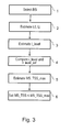
- the current base station BS0 may select (step 1 in figure 3 ) one or a plurality of neighbour base stations BSi and may send this selection to the mobile base station MS, for example by sending a list of neighbour base station identifiers.
- the current base station BSO may also send to the mobile station MS the transmitted signal strength BSi_TSS of each selected neighbour base station BSi and its own transmitted signal strength BS0_TSS.
- the current base station BSO may select the neighbour base stations BSi which are at a distance lower than a maximum distance Dmax of the current base station.
- the current base station BSO may also select the neighbour base stations BSi which are in the first two rings around of its cell C0, for example cells C1 to C18 in figure 1 , the interference being considered as negligible beyond.
- the mobile station MS may estimate a first attenuation value L0 and a second attenuation value Li correlated to the selected neighbour base station BSi ( figure 4 ).
- the first attenuation value L0 is representative of signal attenuation level between the mobile station MS and the current base station BSO
- the second attenuation value Li is representative of signal attenuation level between the mobile station MS and the correlated neighbour base station BSi.
- the mobile station MS receives signals from the current base station and from the neighbour base stations of the network, the mobile station MS can easily estimate the third received signal strength and the first received signal strength.
- the mobile station MS may then report the first and second attenuation values L0, Li to the current base station BSO, for example in a message usually used for handover mechanism.
- the interference level I_level is then for example compared (step 4 in figure 3 ) to a reference interference level I_level_ref.
- the interference level I_level may not be more than a noise floor of the base station BSO plus an additional margin.
- I_level_ref noise floor + margin , wherein:
- the reference interference level I_level_ref may be set differently.
- the reference interference level can be set by an operator of the wireless communication network according to an average interference level measured in the network, or according to other network parameters.
- the reference interference level may also be update according to operating conditions of the network.
- the current station may estimate (step 5 in figure 3 ) and send to the mobile station information relative to a maximum transmitted signal strength MS_TSS_max.
- the mobile station MS may then set (step 6 in figure 3 ) its transmitted signal strength MS_TSS according to this maximum transmitted signal strength MS_TSS_max.
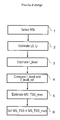
- the current base station can optimize the transmit power level of the mobile station in order to maximize the power of the received signal strength BS0_RSS at a receive antennas BS0_RX of the current base station without exceeding the maximum power level of the signal received at a receive antenna BSi_RX of the neighbour station.
- the received signal strength BSi_RSS of the neighbour base stations should not exceed a threshold named BSi_RSS_max. This threshold may be defined by an operator and may be set for example to the maximum level of noise a mobile station can generate without the neighbour base station to detect it, that is to say the noise floor of the neighbour base station.
- the mobile station MS may estimate the first attenuation value L0 and a plurality of second attenuation values Li.
- each second attenuation value (Li) among the plurality of second attenuation values is correlated to one neighbour base station (BSi) among the plurality of neighbour base stations (for example L1 correlated with BS1, L2 correlated with BS2, Li correlated with BSi).
- Each second attenuation value Li is representative of signal attenuation level between the mobile station MS and the neighbour base station BSi with which it is correlated.
- the relation seen above used to estimate the second attenuation value may also be used to estimate each second attenuation value of the plurality of second attenuation values in this case.
- the mobile station MS may then report the first and all the second attenuation values L0, Li to the current base station BSO, and in this case, the lowest second attenuation value Li among the plurality of estimated second attenuation values is chosen as the parameter L in the relation used to estimate the interference level I_level, as seen above.
- the current base station BS0 has computed the interference level I_level generated by the mobile station, the current base station will be able to discriminate if this particular mobile station generates too much interference on the given neighbour station.
- the current base station is able to reduce the transmit power of a mobile station generating high interference on a neighbour base station without penalizing any other user in the cell.
Abstract
- selecting (1) at least one neighbour base station (BSi);
- estimating (2) a first attenuation value (L0) between the mobile station (MS) and a current base station (BS0), and at least a second attenuation value (Li) between the mobile station (MS) and the neighbour base station;
- estimating (3) an interference level:
- SSO_RSS being a first received signal strength at the base station (BS0), from the mobile station (MS),
- L0 being the first attenuation value, and
- L being one second attenuation value estimated in step B,
- comparing (4) the interference level (I_level) to a reference interference level (I_level_ref), and according to the result of the comparison, sending to the mobile station at least information relative to a maximum transmitted signal strength (MS_TSS_max).
Description
- The present invention pertains to wireless communication, and more specifically to a method for controlling uplink interference level generated by a mobile station communicating with a current base station, on at least a neighbour base station in a wireless communication system. The method comprises at least a step of selecting at least one neighbour base station, and a step of estimating an attenuation level between the mobile station and the current base station, and at least an attenuation level between the mobile station and the neighbour base station.
- A wireless communication network comprises a plurality of zones or cells, for example C0 to C18 in
figure 1 , each zone may comprise a base station. The base station with which a mobile station does communicate, is called the current (or serving) base station, and the other base stations of the network with which the mobile station does not communicate, are called the neighbor base stations. For example infigure 2 , the base station BSO of cell C0 with which the mobile station communicates is the current base station, and the other base stations BSi, i being an integer at least equal to 1 and being the reference number of the cells, are the neighbor base stations. Generally, signal sent in such a network comprises a plurality of frames, each of which comprises data and information relative to the sender station (mobile station or base station) and at least one recipient station (mobile station or base station) of the data. The communication between a base station and a mobile station is bidirectional: transmission from the base station to the mobile station is referred to as downlink, and transmission from a mobile station to a base station is referred to as uplink. Therefore, downlink signals coexist with uplink signals, and particularly in uplink communication, a signal transmitted by the mobile station MS to the current base station BS0 is received by the current base station BSO and also by the neighbor base stations BSi. In such a network, the receiving performance of the neighbor base station is limited by a thermal noise and a co-channel interference generated by the mobile station on the neighbor base station, and the capacity of the uplink is reduced. For example, infigure 2 , considering the cell C0, the mobile station MS communicates with the current base station BS0, and interferes on the neighbor base station BS1 to BSi. Therefore, the level of the uplink interference generated by the mobile stations on the neighbor base stations in a wireless communication network has to be controlled and limited. - The control of the uplink interference can be performed in different ways. For example, a solution, referred to as frequency planning, consists in deploying base stations on the network in such a way that two neighbor base stations do not use the same carrier frequency and this way do not interfere one on another, though this solution leads to important deployment costs. In another solution, each base station filters part of the interference generated by the mobile stations located in the neighboring cells while demodulating the received signal, but this interference cancellation technique requires an increased number of receiving antennas at the base station side and a complex receiving signal processing. In another solution, a base station of a cell controls the average interference level generated by all the mobile stations present in the cell by limiting the number of users that can be allowed in the cell, but this solution does not allow identifying the mobile station which is creating more interference on neighbor cells than the other mobile stations, and thus penalizes mobile stations that are not the source of the interference. In the solution suggested by the patent application
US 5,603,093 , a plurality of field intensities and bit error rate (BER) of downlink radio wave are measured at different measurement timing, and are used in a complex statistical calculation. Moreover, an accurate bit error rate measurement requires long time to be obtained, and in addition, this solution needs to wait for an algorithm to converge in order to know the state of the interference. - The purpose of the present invention is to overcome these disadvantages by proposing a less complex method for controlling the interference level generated by a mobile station on the network.
- For this purpose, an object of the invention is to provide a method for controlling the interference level generated by a mobile station, communicating with a current base station, on at least a neighbor base station in a wireless communication system.
- The method comprises at least steps:
- A: selecting at least one neighbor base station;
- B: estimating a first attenuation value representative of signal attenuation level between the mobile station and the current base station, and at least a second attenuation value correlated to one neighbor base station selected in step A and representative of signal attenuation level between the mobile station and the correlated neighbor base station;
- C': estimating a first received signal strength by measuring power level of signal received by the current base station from the mobile station;
- C": estimating an interference level from the relation: I_level = BS0_RSS + L0 - L, in which
- I_level is the interference level,
- BS0_RSS is the first received signal strength representative of power of signal received by the current base station from the mobile station,
- L0 is the first attenuation value, and
- L is one second attenuation value estimated in step B,
- D: comparing the interference level to a reference interference level, and according to the result of the comparison, sending to the mobile station at least information relative to a maximum transmitted signal strength for the mobile station.
- Thus, the mobile station can set its transmitted signal strength equal or lower than the maximum transmitted signal strength in order to reduce the interference level generated on the neighbour station of the network.
- Advantageously, the wireless communication network may comprise one or a plurality of neighbor stations. In step A, a plurality of neighbour base stations may be selected. In step B, the first attenuation value and a plurality of second attenuation values may be estimated, each second attenuation value among the plurality of second attenuation values being correlated to one neighbour base station among the plurality of neighbour base stations, and being representative of signal attenuation level between the mobile station and the correlated neighbour base station. In step C", L may be the lowest second attenuation value among the plurality of estimated second attenuation values.
- Therefore, a given current base station of a cell can identify the mobile station present in the cell that would generate too much interference and can solve the issue by limiting the transmitted signal strength of this mobile station. Thus, the given current base station controls the uplink transmission of this mobile station without penalizing the other mobile stations present in the cell, and the overall capacity of the network is maximized.
- Preferably, the first attenuation value is estimated from the relation:

- L0 is the first attenuation value,
- BS0_TSS is a first transmitted signal strength representative of power of signal transmitted by the current base station, and
- MS_RSS0 is a second received signal strength representative of power of signal received by the mobile station from the current base station.
- For example, each second attenuation value is estimated from the relation:

- Li is the second attenuation value,
- BSi_TSS is a second transmitted signal strength representative of power of signal transmitted by the correlated neighbour base station, and
- MS_RSSi is a third received signal strength representative of power of signal received by the mobile station from the correlated neighbour base station.
- A wireless communication system may comprise a current base station, a mobile station and at least a neighbour base station.
- The current base station may perform steps A, C', C" and D, and may send to the mobile station information relative to neighbour base stations selected in step A. The mobile station may perform the step B, may receive information relative to at least the first and second transmitted signal strengths BS0_TSS, BSi_TSS, and may send at least the first and the second attenuation level of step B to the current base station. The transmitted signal strength of the mobile station may be set according to the maximum transmitted signal strength. For example, the transmitted signal level of the mobile station should not exceed the maximum transmitted signal strength.
- Other features and advantages of the invention will appear more clearly from the description of one embodiment of the invention made hereinafter, as an indication and by no means restrictive, with reference to the accompanying drawings, wherein:
-
Figure 1 shows cells of a wireless communication network; -
Figure 2 shows cells with mobile station and base stations; -
Figure 3 shows a flowchart of the method according to a particular embodiment of the invention; -
Figure 4 shows propagation loss estimation; and -
Figure 5 shows optimization of the transmitted signal strength of the mobile station. - In a particular embodiment, to control the interference level generated by each mobile station present in a cell, on each neighbour base station, the signal attenuation level (or propagation loss) between a given mobile station and a given neighbour base station, and the signal attenuation level between the base station and the mobile station have to be estimated. Each mobile station and each base station transmit at their own transmitted signal level (TSS), and have a given received signal level (RSS) at each mobile station and base station receiver inputs of the network. For example, considering the cells C0 and Ci of the network, each of which comprising a base station, noted respectively BSO and BSi (
figure 2 ). The mobile station MS being in the cell C0, the base station BSO is the current (or serving) base station and the base station BSi is the neighbour base station. The current base station BSO transmits at a first transmitted signal level, noted BS0_TSS, and receives signal from the mobile station MS with a first received signal strength BS0_RSS. The mobile station MS receives signal from the current base station BSO with a second received signal strength MS_RSS0, and receives signal from the neighbour base station BSi with a third received signal strength MS_RSSi. The neighbour base station BSi transmits at a second transmitted signal strength MS_TSSi. - Referring to
figure 3 , the current base station BS0 may select (step 1 infigure 3 ) one or a plurality of neighbour base stations BSi and may send this selection to the mobile base station MS, for example by sending a list of neighbour base station identifiers. The current base station BSO may also send to the mobile station MS the transmitted signal strength BSi_TSS of each selected neighbour base station BSi and its own transmitted signal strength BS0_TSS. For example, the current base station BSO may select the neighbour base stations BSi which are at a distance lower than a maximum distance Dmax of the current base station. The current base station BSO may also select the neighbour base stations BSi which are in the first two rings around of its cell C0, for example cells C1 to C18 infigure 1 , the interference being considered as negligible beyond. - For example, when only one neighbour base station BSi is selected, the mobile station MS may estimate a first attenuation value L0 and a second attenuation value Li correlated to the selected neighbour base station BSi (
figure 4 ). The first attenuation value L0 is representative of signal attenuation level between the mobile station MS and the current base station BSO, and the second attenuation value Li is representative of signal attenuation level between the mobile station MS and the correlated neighbour base station BSi. - The first attenuation value L0 may be estimated (
step 2 infigure 3 ) by the mobile station from the relation:
in which - L0 is the first attenuation value,
- BS0_TSS is the first transmitted signal strength representative of power of signal transmitted by the current base station on one of its transmit antennas BS0_TX, BS0_TSS may have been sent to the mobile station by the base station, and
- MS_RSS0 is the second received signal strength representative of power of signal received from the current base station by the mobile station on one of its receive antennas MS_RX, MS_RSS0 may have been estimated by the mobile station by measuring power level of signal received from the current base station.
- The second attenuation value Li may be estimated (
step 2 infigure 3 ) by the mobile station MS from the relation:
in which - Li is the second attenuation value,
- BSi_TSS is the second transmitted signal strength representative of power of signal transmitted by the selected neighbour base station on one of its transmit antennas BSi_TX, BS0_TSS may have been sent to the mobile station by the base station, and
- MS_RSSi is the third received signal strength representative of power of signal received from the selected neighbour base station by the mobile station on one of its receive antennas MS_RX, MS_RSS0 may have been estimated by the mobile station by measuring power level of signal received from the selected neighbour base station.
- As the mobile station MS receives signals from the current base station and from the neighbour base stations of the network, the mobile station MS can easily estimate the third received signal strength and the first received signal strength.
- The mobile station MS may then report the first and second attenuation values L0, Li to the current base station BSO, for example in a message usually used for handover mechanism.
- Given these propagation losses, the current base station BSO is able to compute (
step 3 infigure 3 ) the interference level I_level generated by the mobile station on the network by using the following relation:
in which - I_level is the interference level generated by the mobile station,
- BSO_RSS is the first received signal strength representative of power of signal received by the current base station BSO from the mobile station MS, BS0_RSS may have been estimated by the current base station by measuring power level of signal received from the mobile station,
- L0 is the first attenuation value, and
- L is the second attenuation value estimated.
- The interference level I_level is then for example compared (
step 4 infigure 3 ) to a reference interference level I_level_ref. - For example, the interference level I_level may not be more than a noise floor of the base station BSO plus an additional margin. The noise level or noise floor may be estimated from the following relation:

- -134 is a thermal noise for 10 kHz subcarrier spacing expressed in dBm, and
- noise figure is a measure of the degradation of the signal to noise ratio caused by components in radio frequency (RF) signal chain and is typically equal to 6dB.
- The reference interference level can then be derived from the following relation:

wherein: - margin is equal to -3dB and is representative of a margin used to compensate for estimation errors on L0 and L done by the mobile station.
- Therefore, in this example, the reference interference level is equal to -131dBm (I_level_ref = -134+6-3), and the interference level I_level may not exceed -131 dBm.
- Of course, the reference interference level I_level_ref may be set differently. For example, the reference interference level can be set by an operator of the wireless communication network according to an average interference level measured in the network, or according to other network parameters. The reference interference level may also be update according to operating conditions of the network.
- According to the result of the comparison between the interference level and the reference interference level, the current station may estimate (
step 5 infigure 3 ) and send to the mobile station information relative to a maximum transmitted signal strength MS_TSS_max. The mobile station MS may then set (step 6 infigure 3 ) its transmitted signal strength MS_TSS according to this maximum transmitted signal strength MS_TSS_max. - Thus, (
figure 5 ) the current base station can optimize the transmit power level of the mobile station in order to maximize the power of the received signal strength BS0_RSS at a receive antennas BS0_RX of the current base station without exceeding the maximum power level of the signal received at a receive antenna BSi_RX of the neighbour station. The received signal strength BSi_RSS of the neighbour base stations should not exceed a threshold named BSi_RSS_max. This threshold may be defined by an operator and may be set for example to the maximum level of noise a mobile station can generate without the neighbour base station to detect it, that is to say the noise floor of the neighbour base station. - When a plurality of neighbour base stations BSi are selected, the mobile station MS may estimate the first attenuation value L0 and a plurality of second attenuation values Li. In this case, each second attenuation value (Li) among the plurality of second attenuation values is correlated to one neighbour base station (BSi) among the plurality of neighbour base stations (for example L1 correlated with BS1, L2 correlated with BS2, Li correlated with BSi). Each second attenuation value Li is representative of signal attenuation level between the mobile station MS and the neighbour base station BSi with which it is correlated. Of course, the relation seen above used to estimate the second attenuation value may also be used to estimate each second attenuation value of the plurality of second attenuation values in this case. The mobile station MS may then report the first and all the second attenuation values L0, Li to the current base station BSO, and in this case, the lowest second attenuation value Li among the plurality of estimated second attenuation values is chosen as the parameter L in the relation used to estimate the interference level I_level, as seen above. Once the current base station BS0 has computed the interference level I_level generated by the mobile station, the current base station will be able to discriminate if this particular mobile station generates too much interference on the given neighbour station.
- Accordingly, the current base station is able to reduce the transmit power of a mobile station generating high interference on a neighbour base station without penalizing any other user in the cell.
- With this solution, there is no need to wait for a filtering to converge before applying a correction, and this gives a great stability and robustness to the network.
Claims (5)
- Method for controlling the interference level generated by a mobile station (MS) communicating with a current base station (BS0) on at least a neighbour base station (BSi) in a wireless communication system, comprising at least steps:A: selecting (1) at least one neighbour base station;B: estimating (2) a first attenuation value (L0) representative of signal attenuation level between the mobile station (MS) and the current base station (BS0), and at least a second attenuation value (Li) correlated to one neighbour base station selected in step A and representative of signal attenuation level between the mobile station and the correlated neighbour base station;
characterized in that it further comprises steps:C': estimating a first received signal strength (BS0_RSS) by measuring power level of signal received by the current base station (BS0) from the mobile station (MS);C": estimating (3) an interference level (I_level) from the relation: I_level = BS0_RSS + L0 - L, in which- I_level is the interference level,- BS0_RSS is the first received signal strength,- L0 is the first attenuation value, and- L is one second attenuation value estimated in step B,D: comparing (4) the interference level (I_level) to a reference interference level (I_level_ref), and according to the result of the comparison, sending to the mobile station at least information relative to a maximum transmitted signal strength (MS_TSS_max) for the mobile station (MS). - Method according to claim 1,
wherein in step A, a plurality of neighbour base stations (BSi) are selected,
wherein in step B, the first attenuation value (L0) and a plurality of second attenuation values (Li) are estimated, each second attenuation value (Li) among the plurality of second attenuation values being correlated to one neighbour base station (BSi) among the plurality of neighbour base stations, and being representative of signal attenuation level between the mobile station (MS) and the correlated neighbour base station (BSi); and
wherein in step C", L is the lowest second attenuation value (Li) among the plurality of estimated second attenuation values. - Method according to claim 1 or 2, wherein the first attenuation value (L0) is estimating from the relation:
 - L0 is the first attenuation value,- BS0_TSS is a first transmitted signal strength representative of power of signal transmitted by the current base station, and- MS_RSS0 is a second received signal strength representative of power of signal received by the mobile station from the current base station.
 - Method according to any of claims 1 to 3, wherein each second attenuation value (Li) is estimated from the relation:
 - Li is the second attenuation value,- BSi_TSS is a second transmitted signal strength representative of power of signal transmitted by the correlated neighbour base station, and- MS_RSSi is a third received signal strength representative of power of signal received by the mobile station from the correlated neighbour base station.
 - Method according to any of claims 1 to 4, wherein- the current base station (BS0) performs steps A, C', C'' and D, and sends to the mobile station (MS) information relative to neighbour base stations selected in step A;- the mobile station (MS) performs the step B, receives information relative to at least the first and second transmitted signal strengths BS0_TSS, BSi_TSS, sends the first and at least the second attenuation level (L0, Li) of step B to the current base station (BS0);- the transmitted signal strength MS_TSS of the mobile station (MS) is set according to the maximum transmitted signal strength (MS_TSS_max).
Priority Applications (3)
| Application Number | Priority Date | Filing Date | Title |
|---|---|---|---|
| AT08290239T ATE535118T1 (en) | 2008-03-12 | 2008-03-12 | METHOD FOR CONTROLLING INTERFERENCE GENERATED BY A MOBILE STATION ON NEIGHBOR BASE STATIONS |
| EP08290239A EP2101418B1 (en) | 2008-03-12 | 2008-03-12 | Method for controlling interference generated by a mobile station on neighbour base stations |
| US12/399,905 US8219137B2 (en) | 2008-03-12 | 2009-03-06 | Method for controlling interference generated by a mobile station on neighbor base stations |
Applications Claiming Priority (1)
| Application Number | Priority Date | Filing Date | Title |
|---|---|---|---|
| EP08290239A EP2101418B1 (en) | 2008-03-12 | 2008-03-12 | Method for controlling interference generated by a mobile station on neighbour base stations |
Publications (2)
| Publication Number | Publication Date |
|---|---|
| EP2101418A1 true EP2101418A1 (en) | 2009-09-16 |
| EP2101418B1 EP2101418B1 (en) | 2011-11-23 |
Family
ID=39711857
Family Applications (1)
| Application Number | Title | Priority Date | Filing Date |
|---|---|---|---|
| EP08290239A Not-in-force EP2101418B1 (en) | 2008-03-12 | 2008-03-12 | Method for controlling interference generated by a mobile station on neighbour base stations |
Country Status (3)
| Country | Link |
|---|---|
| US (1) | US8219137B2 (en) |
| EP (1) | EP2101418B1 (en) |
| AT (1) | ATE535118T1 (en) |
Cited By (2)
| Publication number | Priority date | Publication date | Assignee | Title |
|---|---|---|---|---|
| WO2014059935A1 (en) * | 2012-10-17 | 2014-04-24 | Huawei Technologies Co., Ltd. | System and Method for Dynamic Inter-Cell Interference Coordination |
| WO2015028723A1 (en) * | 2013-08-29 | 2015-03-05 | Cassidian Sas | Method for defining parameter values for controlling the transmission power of a piece of user equipment |
Families Citing this family (9)
| Publication number | Priority date | Publication date | Assignee | Title |
|---|---|---|---|---|
| EP2246991B1 (en) * | 2009-04-27 | 2013-11-06 | Alcatel Lucent | Uplink communication in a wireless communication network |
| US8379551B2 (en) * | 2009-08-18 | 2013-02-19 | Qualcomm Incorporated | Radio selection in a multi-radio device |
| US8738065B2 (en) * | 2009-10-02 | 2014-05-27 | Kyocera Corporation | Radio communication system, large cell base station, and communication control method |
| US9237459B1 (en) * | 2010-12-10 | 2016-01-12 | Marvell International Ltd | System and method for measuring characteristics of neighbor cells using a synthesized composite antenna pattern |
| WO2013141652A1 (en) * | 2012-03-22 | 2013-09-26 | 엘지전자 주식회사 | Method for measuring interference strength in wireless communication system and device therefor |
| US10560244B2 (en) * | 2013-07-24 | 2020-02-11 | At&T Intellectual Property I, L.P. | System and method for reducing inter-cellsite interference in full-duplex communications |
| US9451558B2 (en) * | 2013-08-20 | 2016-09-20 | Qualcomm Incorporated | Adaptive transmit power control in a communication network |
| US11158185B2 (en) * | 2017-07-28 | 2021-10-26 | Beijing Xiaomi Mobile Software Co., Ltd. | Method and apparatus for controlling controllable device |
| WO2019019164A1 (en) * | 2017-07-28 | 2019-01-31 | 北京小米移动软件有限公司 | Unmanned aerial vehicle management method and apparatus, and communication connection establishment method and apparatus |
Citations (4)
| Publication number | Priority date | Publication date | Assignee | Title |
|---|---|---|---|---|
| US5603093A (en) | 1994-12-28 | 1997-02-11 | Ntt Mobile Communications Network, Inc. | Method for monitoring the state of interference by a base station of a mobile radio communication system |
| WO2003094544A1 (en) * | 2002-04-29 | 2003-11-13 | Nokia Corporation | Method and apparatus for ul interference avoidance by dl measurements and ifho |
| WO2004075423A2 (en) * | 2003-02-19 | 2004-09-02 | Motorola Inc. | Multimode background scans of different communication systems on similar frequencies |
| EP1873925A1 (en) * | 2005-04-20 | 2008-01-02 | Mitsubishi Denki Kabushiki Kaisha | Communication quality judgement method, mobile station, base station, and communication system |
Family Cites Families (3)
| Publication number | Priority date | Publication date | Assignee | Title |
|---|---|---|---|---|
| FI934759A (en) * | 1993-10-27 | 1995-04-28 | Nokia Telecommunications Oy | Procedure for the elimination of multi-use interference and mobile station |
| US7647025B2 (en) * | 2006-09-29 | 2010-01-12 | Alcatel-Lucent Usa Inc. | Method for adaptively controlling and coordinating other cell interference |
| US8717914B2 (en) * | 2009-04-29 | 2014-05-06 | Samsung Electronics Co., Ltd. | Method for controlling interference |
-
2008
- 2008-03-12 EP EP08290239A patent/EP2101418B1/en not_active Not-in-force
- 2008-03-12 AT AT08290239T patent/ATE535118T1/en active
-
2009
- 2009-03-06 US US12/399,905 patent/US8219137B2/en active Active
Patent Citations (4)
| Publication number | Priority date | Publication date | Assignee | Title |
|---|---|---|---|---|
| US5603093A (en) | 1994-12-28 | 1997-02-11 | Ntt Mobile Communications Network, Inc. | Method for monitoring the state of interference by a base station of a mobile radio communication system |
| WO2003094544A1 (en) * | 2002-04-29 | 2003-11-13 | Nokia Corporation | Method and apparatus for ul interference avoidance by dl measurements and ifho |
| WO2004075423A2 (en) * | 2003-02-19 | 2004-09-02 | Motorola Inc. | Multimode background scans of different communication systems on similar frequencies |
| EP1873925A1 (en) * | 2005-04-20 | 2008-01-02 | Mitsubishi Denki Kabushiki Kaisha | Communication quality judgement method, mobile station, base station, and communication system |
Cited By (4)
| Publication number | Priority date | Publication date | Assignee | Title |
|---|---|---|---|---|
| WO2014059935A1 (en) * | 2012-10-17 | 2014-04-24 | Huawei Technologies Co., Ltd. | System and Method for Dynamic Inter-Cell Interference Coordination |
| US10085154B2 (en) | 2012-10-17 | 2018-09-25 | Huawei Technologies Co., Ltd. | System and method for dynamic inter-cell interference coordination |
| WO2015028723A1 (en) * | 2013-08-29 | 2015-03-05 | Cassidian Sas | Method for defining parameter values for controlling the transmission power of a piece of user equipment |
| US9756577B2 (en) | 2013-08-29 | 2017-09-05 | Airbus Ds Sas | Method for defining parameter values for controlling the transmission power of a piece of user equipment |
Also Published As
| Publication number | Publication date |
|---|---|
| US8219137B2 (en) | 2012-07-10 |
| US20090233594A1 (en) | 2009-09-17 |
| EP2101418B1 (en) | 2011-11-23 |
| ATE535118T1 (en) | 2011-12-15 |
Similar Documents
| Publication | Publication Date | Title |
|---|---|---|
| EP2101418B1 (en) | Method for controlling interference generated by a mobile station on neighbour base stations | |
| US8913530B2 (en) | Dynamic band selection for interference minimization in direct device to device communications | |
| US10368357B2 (en) | Mitigating UL-to-DL interference | |
| CN106134236B (en) | Method and apparatus for tracking uplink beam | |
| RU2521522C2 (en) | Pilot signals for use in multi-sector cells | |
| US8792881B2 (en) | Method and apparatus for determining cell for executing comp in multi-cell environment | |
| KR200296459Y1 (en) | A user equipment which determines whether to initiate handover | |
| EP1750472B1 (en) | Apparatus and method for performing handoff in a communication system | |
| US9369996B2 (en) | Base station apparatus, user apparatus and communication control method | |
| EP2247143A1 (en) | Relay transmission system, base station, relay station, and method | |
| EP2945451A1 (en) | Interference reduction in a communication network by scheduling and link adaptation | |
| IL206838A (en) | Serving base station selection in a wireless communication network | |
| JP2005525041A (en) | Antenna adaptation in time division duplex systems | |
| EP1228582A1 (en) | Downlink signal processing in cdma systems utilizing arrays of antennas | |
| EP2373096B1 (en) | Method for selecting a relay station | |
| CA2582366C (en) | Mitigating intermodulation interference using channel power estimation and attenuation in a two-way radio communications system | |
| CN104145512B (en) | Power control in wireless communication system | |
| US9048973B2 (en) | Base station device | |
| Abrardo et al. | Network coding schemes for device-to-device communications based relaying for cellular coverage extension | |
| WO2015154934A1 (en) | Mitigating dl-ul interference | |
| US6907014B1 (en) | Apparatus and method for TDMA-TDD based transmission/reception | |
| JP2004266538A (en) | Mobile communication system, radio controller, base station and transmission power control method | |
| KR100898333B1 (en) | Underlay transmission method in cognitive radio based wireless communication system | |
| Cierny et al. | SINR prediction versus reverse reporting for soft reuse and interference management | |
| EP1058474A1 (en) | Cellular network with optimised mobile terminals/base stations links and method for determining the same |
Legal Events
| Date | Code | Title | Description |
|---|---|---|---|
| PUAI | Public reference made under article 153(3) epc to a published international application that has entered the european phase |
Free format text: ORIGINAL CODE: 0009012 |
|
| AK | Designated contracting states |
Kind code of ref document: A1 Designated state(s): AT BE BG CH CY CZ DE DK EE ES FI FR GB GR HR HU IE IS IT LI LT LU LV MC MT NL NO PL PT RO SE SI SK TR |
|
| AX | Request for extension of the european patent |
Extension state: AL BA MK RS |
|
| 17P | Request for examination filed |
Effective date: 20100312 |
|
| AKX | Designation fees paid |
Designated state(s): AT BE BG CH CY CZ DE DK EE ES FI FR GB GR HR HU IE IS IT LI LT LU LV MC MT NL NO PL PT RO SE SI SK TR |
|
| REG | Reference to a national code |
Ref country code: DE Ref legal event code: R079 Ref document number: 602008011537 Country of ref document: DE Free format text: PREVIOUS MAIN CLASS: H04B0007005000 Ipc: H04W0052240000 |
|
| RIC1 | Information provided on ipc code assigned before grant |
Ipc: H04W 52/24 20090101AFI20110411BHEP Ipc: H04B 17/00 20060101ALI20110411BHEP |
|
| GRAP | Despatch of communication of intention to grant a patent |
Free format text: ORIGINAL CODE: EPIDOSNIGR1 |
|
| GRAS | Grant fee paid |
Free format text: ORIGINAL CODE: EPIDOSNIGR3 |
|
| GRAA | (expected) grant |
Free format text: ORIGINAL CODE: 0009210 |
|
| AK | Designated contracting states |
Kind code of ref document: B1 Designated state(s): AT BE BG CH CY CZ DE DK EE ES FI FR GB GR HR HU IE IS IT LI LT LU LV MC MT NL NO PL PT RO SE SI SK TR |
|
| REG | Reference to a national code |
Ref country code: GB Ref legal event code: FG4D |
|
| REG | Reference to a national code |
Ref country code: CH Ref legal event code: EP |
|
| REG | Reference to a national code |
Ref country code: IE Ref legal event code: FG4D |
|
| REG | Reference to a national code |
Ref country code: DE Ref legal event code: R096 Ref document number: 602008011537 Country of ref document: DE Effective date: 20120119 |
|
| REG | Reference to a national code |
Ref country code: NL Ref legal event code: VDEP Effective date: 20111123 |
|
| LTIE | Lt: invalidation of european patent or patent extension |
Effective date: 20111123 |
|
| PG25 | Lapsed in a contracting state [announced via postgrant information from national office to epo] |
Ref country code: IS Free format text: LAPSE BECAUSE OF FAILURE TO SUBMIT A TRANSLATION OF THE DESCRIPTION OR TO PAY THE FEE WITHIN THE PRESCRIBED TIME-LIMIT Effective date: 20120323 Ref country code: LT Free format text: LAPSE BECAUSE OF FAILURE TO SUBMIT A TRANSLATION OF THE DESCRIPTION OR TO PAY THE FEE WITHIN THE PRESCRIBED TIME-LIMIT Effective date: 20111123 Ref country code: NO Free format text: LAPSE BECAUSE OF FAILURE TO SUBMIT A TRANSLATION OF THE DESCRIPTION OR TO PAY THE FEE WITHIN THE PRESCRIBED TIME-LIMIT Effective date: 20120223 |
|
| PG25 | Lapsed in a contracting state [announced via postgrant information from national office to epo] |
Ref country code: SI Free format text: LAPSE BECAUSE OF FAILURE TO SUBMIT A TRANSLATION OF THE DESCRIPTION OR TO PAY THE FEE WITHIN THE PRESCRIBED TIME-LIMIT Effective date: 20111123 Ref country code: PT Free format text: LAPSE BECAUSE OF FAILURE TO SUBMIT A TRANSLATION OF THE DESCRIPTION OR TO PAY THE FEE WITHIN THE PRESCRIBED TIME-LIMIT Effective date: 20120323 Ref country code: NL Free format text: LAPSE BECAUSE OF FAILURE TO SUBMIT A TRANSLATION OF THE DESCRIPTION OR TO PAY THE FEE WITHIN THE PRESCRIBED TIME-LIMIT Effective date: 20111123 Ref country code: BE Free format text: LAPSE BECAUSE OF FAILURE TO SUBMIT A TRANSLATION OF THE DESCRIPTION OR TO PAY THE FEE WITHIN THE PRESCRIBED TIME-LIMIT Effective date: 20111123 Ref country code: HR Free format text: LAPSE BECAUSE OF FAILURE TO SUBMIT A TRANSLATION OF THE DESCRIPTION OR TO PAY THE FEE WITHIN THE PRESCRIBED TIME-LIMIT Effective date: 20111123 Ref country code: GR Free format text: LAPSE BECAUSE OF FAILURE TO SUBMIT A TRANSLATION OF THE DESCRIPTION OR TO PAY THE FEE WITHIN THE PRESCRIBED TIME-LIMIT Effective date: 20120224 Ref country code: SE Free format text: LAPSE BECAUSE OF FAILURE TO SUBMIT A TRANSLATION OF THE DESCRIPTION OR TO PAY THE FEE WITHIN THE PRESCRIBED TIME-LIMIT Effective date: 20111123 Ref country code: LV Free format text: LAPSE BECAUSE OF FAILURE TO SUBMIT A TRANSLATION OF THE DESCRIPTION OR TO PAY THE FEE WITHIN THE PRESCRIBED TIME-LIMIT Effective date: 20111123 |
|
| PG25 | Lapsed in a contracting state [announced via postgrant information from national office to epo] |
Ref country code: CY Free format text: LAPSE BECAUSE OF FAILURE TO SUBMIT A TRANSLATION OF THE DESCRIPTION OR TO PAY THE FEE WITHIN THE PRESCRIBED TIME-LIMIT Effective date: 20111123 |
|
| PG25 | Lapsed in a contracting state [announced via postgrant information from national office to epo] |
Ref country code: EE Free format text: LAPSE BECAUSE OF FAILURE TO SUBMIT A TRANSLATION OF THE DESCRIPTION OR TO PAY THE FEE WITHIN THE PRESCRIBED TIME-LIMIT Effective date: 20111123 Ref country code: CZ Free format text: LAPSE BECAUSE OF FAILURE TO SUBMIT A TRANSLATION OF THE DESCRIPTION OR TO PAY THE FEE WITHIN THE PRESCRIBED TIME-LIMIT Effective date: 20111123 Ref country code: DK Free format text: LAPSE BECAUSE OF FAILURE TO SUBMIT A TRANSLATION OF THE DESCRIPTION OR TO PAY THE FEE WITHIN THE PRESCRIBED TIME-LIMIT Effective date: 20111123 Ref country code: BG Free format text: LAPSE BECAUSE OF FAILURE TO SUBMIT A TRANSLATION OF THE DESCRIPTION OR TO PAY THE FEE WITHIN THE PRESCRIBED TIME-LIMIT Effective date: 20120223 Ref country code: SK Free format text: LAPSE BECAUSE OF FAILURE TO SUBMIT A TRANSLATION OF THE DESCRIPTION OR TO PAY THE FEE WITHIN THE PRESCRIBED TIME-LIMIT Effective date: 20111123 |
|
| PG25 | Lapsed in a contracting state [announced via postgrant information from national office to epo] |
Ref country code: IT Free format text: LAPSE BECAUSE OF FAILURE TO SUBMIT A TRANSLATION OF THE DESCRIPTION OR TO PAY THE FEE WITHIN THE PRESCRIBED TIME-LIMIT Effective date: 20111123 Ref country code: PL Free format text: LAPSE BECAUSE OF FAILURE TO SUBMIT A TRANSLATION OF THE DESCRIPTION OR TO PAY THE FEE WITHIN THE PRESCRIBED TIME-LIMIT Effective date: 20111123 Ref country code: RO Free format text: LAPSE BECAUSE OF FAILURE TO SUBMIT A TRANSLATION OF THE DESCRIPTION OR TO PAY THE FEE WITHIN THE PRESCRIBED TIME-LIMIT Effective date: 20111123 |
|
| REG | Reference to a national code |
Ref country code: AT Ref legal event code: MK05 Ref document number: 535118 Country of ref document: AT Kind code of ref document: T Effective date: 20111123 |
|
| PLBE | No opposition filed within time limit |
Free format text: ORIGINAL CODE: 0009261 |
|
| STAA | Information on the status of an ep patent application or granted ep patent |
Free format text: STATUS: NO OPPOSITION FILED WITHIN TIME LIMIT |
|
| 26N | No opposition filed |
Effective date: 20120824 |
|
| PG25 | Lapsed in a contracting state [announced via postgrant information from national office to epo] |
Ref country code: MC Free format text: LAPSE BECAUSE OF NON-PAYMENT OF DUE FEES Effective date: 20120331 |
|
| REG | Reference to a national code |
Ref country code: CH Ref legal event code: PL |
|
| REG | Reference to a national code |
Ref country code: DE Ref legal event code: R097 Ref document number: 602008011537 Country of ref document: DE Effective date: 20120824 |
|
| REG | Reference to a national code |
Ref country code: IE Ref legal event code: MM4A |
|
| PG25 | Lapsed in a contracting state [announced via postgrant information from national office to epo] |
Ref country code: IE Free format text: LAPSE BECAUSE OF NON-PAYMENT OF DUE FEES Effective date: 20120312 Ref country code: CH Free format text: LAPSE BECAUSE OF NON-PAYMENT OF DUE FEES Effective date: 20120331 Ref country code: AT Free format text: LAPSE BECAUSE OF FAILURE TO SUBMIT A TRANSLATION OF THE DESCRIPTION OR TO PAY THE FEE WITHIN THE PRESCRIBED TIME-LIMIT Effective date: 20111123 Ref country code: LI Free format text: LAPSE BECAUSE OF NON-PAYMENT OF DUE FEES Effective date: 20120331 |
|
| PG25 | Lapsed in a contracting state [announced via postgrant information from national office to epo] |
Ref country code: ES Free format text: LAPSE BECAUSE OF FAILURE TO SUBMIT A TRANSLATION OF THE DESCRIPTION OR TO PAY THE FEE WITHIN THE PRESCRIBED TIME-LIMIT Effective date: 20120305 |
|
| PG25 | Lapsed in a contracting state [announced via postgrant information from national office to epo] |
Ref country code: FI Free format text: LAPSE BECAUSE OF FAILURE TO SUBMIT A TRANSLATION OF THE DESCRIPTION OR TO PAY THE FEE WITHIN THE PRESCRIBED TIME-LIMIT Effective date: 20111123 |
|
| PG25 | Lapsed in a contracting state [announced via postgrant information from national office to epo] |
Ref country code: MT Free format text: LAPSE BECAUSE OF FAILURE TO SUBMIT A TRANSLATION OF THE DESCRIPTION OR TO PAY THE FEE WITHIN THE PRESCRIBED TIME-LIMIT Effective date: 20111123 |
|
| PG25 | Lapsed in a contracting state [announced via postgrant information from national office to epo] |
Ref country code: TR Free format text: LAPSE BECAUSE OF FAILURE TO SUBMIT A TRANSLATION OF THE DESCRIPTION OR TO PAY THE FEE WITHIN THE PRESCRIBED TIME-LIMIT Effective date: 20111123 |
|
| PG25 | Lapsed in a contracting state [announced via postgrant information from national office to epo] |
Ref country code: LU Free format text: LAPSE BECAUSE OF NON-PAYMENT OF DUE FEES Effective date: 20120312 |
|
| PG25 | Lapsed in a contracting state [announced via postgrant information from national office to epo] |
Ref country code: HU Free format text: LAPSE BECAUSE OF FAILURE TO SUBMIT A TRANSLATION OF THE DESCRIPTION OR TO PAY THE FEE WITHIN THE PRESCRIBED TIME-LIMIT Effective date: 20080312 |
|
| REG | Reference to a national code |
Ref country code: FR Ref legal event code: PLFP Year of fee payment: 9 |
|
| REG | Reference to a national code |
Ref country code: FR Ref legal event code: PLFP Year of fee payment: 10 |
|
| PGFP | Annual fee paid to national office [announced via postgrant information from national office to epo] |
Ref country code: FR Payment date: 20170119 Year of fee payment: 10 Ref country code: DE Payment date: 20170327 Year of fee payment: 10 |
|
| PGFP | Annual fee paid to national office [announced via postgrant information from national office to epo] |
Ref country code: GB Payment date: 20170324 Year of fee payment: 10 |
|
| REG | Reference to a national code |
Ref country code: DE Ref legal event code: R119 Ref document number: 602008011537 Country of ref document: DE |
|
| GBPC | Gb: european patent ceased through non-payment of renewal fee |
Effective date: 20180312 |
|
| PG25 | Lapsed in a contracting state [announced via postgrant information from national office to epo] |
Ref country code: DE Free format text: LAPSE BECAUSE OF NON-PAYMENT OF DUE FEES Effective date: 20181002 |
|
| PG25 | Lapsed in a contracting state [announced via postgrant information from national office to epo] |
Ref country code: GB Free format text: LAPSE BECAUSE OF NON-PAYMENT OF DUE FEES Effective date: 20180312 |
|
| PG25 | Lapsed in a contracting state [announced via postgrant information from national office to epo] |
Ref country code: FR Free format text: LAPSE BECAUSE OF NON-PAYMENT OF DUE FEES Effective date: 20180331 |