EP2101398A2 - Superconducting homopolar alternator for wind power applications - Google Patents
Superconducting homopolar alternator for wind power applications Download PDFInfo
- Publication number
- EP2101398A2 EP2101398A2 EP09154818A EP09154818A EP2101398A2 EP 2101398 A2 EP2101398 A2 EP 2101398A2 EP 09154818 A EP09154818 A EP 09154818A EP 09154818 A EP09154818 A EP 09154818A EP 2101398 A2 EP2101398 A2 EP 2101398A2
- Authority
- EP
- European Patent Office
- Prior art keywords
- homopolar
- rotor assembly
- magnetic field
- operative
- superconducting
- Prior art date
- Legal status (The legal status is an assumption and is not a legal conclusion. Google has not performed a legal analysis and makes no representation as to the accuracy of the status listed.)
- Withdrawn
Links
- 230000005291 magnetic effect Effects 0.000 claims abstract description 46
- 238000004804 winding Methods 0.000 claims abstract description 12
- 230000003993 interaction Effects 0.000 claims abstract description 9
- IJGRMHOSHXDMSA-UHFFFAOYSA-N Atomic nitrogen Chemical compound N#N IJGRMHOSHXDMSA-UHFFFAOYSA-N 0.000 claims description 12
- 229910052754 neon Inorganic materials 0.000 claims description 6
- GKAOGPIIYCISHV-UHFFFAOYSA-N neon atom Chemical compound [Ne] GKAOGPIIYCISHV-UHFFFAOYSA-N 0.000 claims description 6
- 229910052757 nitrogen Inorganic materials 0.000 claims description 6
- 230000004907 flux Effects 0.000 description 4
- 238000000034 method Methods 0.000 description 3
- -1 BSCCO Inorganic materials 0.000 description 2
- 239000012530 fluid Substances 0.000 description 2
- 239000000696 magnetic material Substances 0.000 description 2
- 238000010248 power generation Methods 0.000 description 2
- 229910020073 MgB2 Inorganic materials 0.000 description 1
- 238000006243 chemical reaction Methods 0.000 description 1
- 238000004891 communication Methods 0.000 description 1
- 230000001419 dependent effect Effects 0.000 description 1
- 239000003302 ferromagnetic material Substances 0.000 description 1
- 239000007788 liquid Substances 0.000 description 1
- 229910000657 niobium-tin Inorganic materials 0.000 description 1
- 229910021521 yttrium barium copper oxide Inorganic materials 0.000 description 1
Images


Classifications
-
- H—ELECTRICITY
- H02—GENERATION; CONVERSION OR DISTRIBUTION OF ELECTRIC POWER
- H02K—DYNAMO-ELECTRIC MACHINES
- H02K55/00—Dynamo-electric machines having windings operating at cryogenic temperatures
- H02K55/06—Dynamo-electric machines having windings operating at cryogenic temperatures of the homopolar type
-
- H—ELECTRICITY
- H02—GENERATION; CONVERSION OR DISTRIBUTION OF ELECTRIC POWER
- H02K—DYNAMO-ELECTRIC MACHINES
- H02K1/00—Details of the magnetic circuit
- H02K1/06—Details of the magnetic circuit characterised by the shape, form or construction
- H02K1/22—Rotating parts of the magnetic circuit
- H02K1/24—Rotor cores with salient poles ; Variable reluctance rotors
- H02K1/246—Variable reluctance rotors
-
- H—ELECTRICITY
- H02—GENERATION; CONVERSION OR DISTRIBUTION OF ELECTRIC POWER
- H02K—DYNAMO-ELECTRIC MACHINES
- H02K7/00—Arrangements for handling mechanical energy structurally associated with dynamo-electric machines, e.g. structural association with mechanical driving motors or auxiliary dynamo-electric machines
- H02K7/18—Structural association of electric generators with mechanical driving motors, e.g. with turbines
- H02K7/1807—Rotary generators
- H02K7/1823—Rotary generators structurally associated with turbines or similar engines
-
- H—ELECTRICITY
- H02—GENERATION; CONVERSION OR DISTRIBUTION OF ELECTRIC POWER
- H02K—DYNAMO-ELECTRIC MACHINES
- H02K7/00—Arrangements for handling mechanical energy structurally associated with dynamo-electric machines, e.g. structural association with mechanical driving motors or auxiliary dynamo-electric machines
- H02K7/18—Structural association of electric generators with mechanical driving motors, e.g. with turbines
- H02K7/1807—Rotary generators
- H02K7/1823—Rotary generators structurally associated with turbines or similar engines
- H02K7/183—Rotary generators structurally associated with turbines or similar engines wherein the turbine is a wind turbine
-
- H—ELECTRICITY
- H02—GENERATION; CONVERSION OR DISTRIBUTION OF ELECTRIC POWER
- H02K—DYNAMO-ELECTRIC MACHINES
- H02K7/00—Arrangements for handling mechanical energy structurally associated with dynamo-electric machines, e.g. structural association with mechanical driving motors or auxiliary dynamo-electric machines
- H02K7/18—Structural association of electric generators with mechanical driving motors, e.g. with turbines
- H02K7/1807—Rotary generators
- H02K7/1823—Rotary generators structurally associated with turbines or similar engines
- H02K7/183—Rotary generators structurally associated with turbines or similar engines wherein the turbine is a wind turbine
- H02K7/1838—Generators mounted in a nacelle or similar structure of a horizontal axis wind turbine
-
- Y—GENERAL TAGGING OF NEW TECHNOLOGICAL DEVELOPMENTS; GENERAL TAGGING OF CROSS-SECTIONAL TECHNOLOGIES SPANNING OVER SEVERAL SECTIONS OF THE IPC; TECHNICAL SUBJECTS COVERED BY FORMER USPC CROSS-REFERENCE ART COLLECTIONS [XRACs] AND DIGESTS
- Y02—TECHNOLOGIES OR APPLICATIONS FOR MITIGATION OR ADAPTATION AGAINST CLIMATE CHANGE
- Y02E—REDUCTION OF GREENHOUSE GAS [GHG] EMISSIONS, RELATED TO ENERGY GENERATION, TRANSMISSION OR DISTRIBUTION
- Y02E10/00—Energy generation through renewable energy sources
- Y02E10/70—Wind energy
- Y02E10/72—Wind turbines with rotation axis in wind direction
-
- Y—GENERAL TAGGING OF NEW TECHNOLOGICAL DEVELOPMENTS; GENERAL TAGGING OF CROSS-SECTIONAL TECHNOLOGIES SPANNING OVER SEVERAL SECTIONS OF THE IPC; TECHNICAL SUBJECTS COVERED BY FORMER USPC CROSS-REFERENCE ART COLLECTIONS [XRACs] AND DIGESTS
- Y02—TECHNOLOGIES OR APPLICATIONS FOR MITIGATION OR ADAPTATION AGAINST CLIMATE CHANGE
- Y02E—REDUCTION OF GREENHOUSE GAS [GHG] EMISSIONS, RELATED TO ENERGY GENERATION, TRANSMISSION OR DISTRIBUTION
- Y02E40/00—Technologies for an efficient electrical power generation, transmission or distribution
- Y02E40/60—Superconducting electric elements or equipment; Power systems integrating superconducting elements or equipment
Definitions
- superconducting homopolar alternators that include a superconducting field coil that is not installed on a rotor assembly are advantagious in multiple applications. Since superconducting field coils use cryogenic fluid to cool the coils, a non-rotating superconducting field coil simplifies the components used to deliver cryogenic fluid to the coils. Additionally, the electrical connections to the rotor assembly are simplified; since there are no coils on the rotor, electrical connections via brushes or other means are not present. Systems that utilize superconducting homopolar alternators that include a superconducting field coil that is not installed on a rotor assembly for power generation are desired.
- An exemplary embodiment of the present invention includes a system for generating power comprising, a homopolar electrical generator having, a superconducting field coil operative to create a magnetic field, and a homopolar rotor assembly operative to rotate in the magnetic field such that a rotating magnetic field couples with a stationary winding by an interaction of a rotating permeance wave produced by the homopolar rotor assembly and the magnetic field created by the superconducting field coil, and a wind turbine mechanically linked to the homopolar electrical generator operative to rotate the homopolar rotor assembly.
- a wind turbine drive train system for generating electrical power 100 is shown.
- the system 100 includes wind blades 101, a gear box 103, and a superconducting homopolar alternator 105 mechanically linked to the wind blades 101 via the gear box 103 and shafts (not shown).
- a cable 107 is in electrical communication with the superconducting homopolar alternator 105 and a power grid (not shown) and often a power electronics conversion system (not shown).
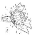
- FIG. 2 illustrates a perspective partially cut-away view of an exemplary embodiment of a superconducting homopolar alternator system 200 that may, for example, be used in the system 100.
- the superconducting homopolar alternator system 200 includes a homopolar rotor assembly 201 that includes poles 202, linked to a shaft assembly 207.
- the poles 202 comprise a ferro-magnetic material.
- the shaft assembly 207 engages bearings 209.
- the illustrated embodiment further includes a stator yoke 203, an armature 205, and a superconducting field coil 211.
- a cryocooler 215 and a re-condenser 213 are also included in the system 200.
- the rotating poles 202 in the homopolar rotor assembly 201 induce a permeance wave of magnetic flux.
- the flux produced by the rotating poles 202 causes a rotating magnetic field that passes through stationary windings in the stator yoke 203 (an armature winding).
- the rotating magnetic field generates a current flow in the stationary windings in the stator yoke 203.
- the homopolar rotor assembly 201 rotates at approximately 200 revolutions per minute (rpm).
- the operational speed of the homopolar rotor assembly 201 will vary based on the speed of the rotation of the wind turbine 101 (caused by varying wind velocities) and the gear ratio of the gear box 103.
- FIG. 3 illustrates a perspective view of an alternate exempliary embodiment of the homopolar rotor assembly 201.
- Fig. 3 includes a radial flux homopolar inductor alternator, however axial flux machines may also be used.
- a lightweight homopolar rotor assembly 300 is shown.
- the lightweight homopolar rotor assembly 300 includes a hub portion 301 having an outer surface 311 and optional inner cavities 303 partially defined by the hub portion 301.
- a polar portion 305 engages an outer circumference 309 of the hub portion 301.
- the polar portion 305 includes a plurality of poles 307.
- FIG. 4 illustrates a front view of the lightweight homopolar rotor assembly 300.
- FIG. 4 shows the outer surface 311 having openings 303. The inner cavity and the openings 303 may be used to reduce the weight of the rotor.
- the use of the lightweight homopolar rotor assembly 300 allows the superconducting homopolar alternator system 200 to operate more efficiently in wind turbine applications.
Landscapes
- Engineering & Computer Science (AREA)
- Power Engineering (AREA)
- Wind Motors (AREA)
- Superconductive Dynamoelectric Machines (AREA)
- Connection Of Motors, Electrical Generators, Mechanical Devices, And The Like (AREA)
Abstract
A system 100 for generating power includes a homopolar electrical generator having, a superconducting field coil 211 operative to create a magnetic field, and a homopolar rotor assembly 201 operative to rotate in the magnetic field such that a rotating magnetic field couples with a stationary winding by an interaction of a rotating permeance wave produced by the homopolar rotor assembly and the magnetic field created by the superconducting field coil, and a wind turbine mechanically linked to the homopolar electrical generator operative to rotate the homopolar rotor assembly 201.
Description
- An embodiment of the invention relates generally to superconducting homopolar alternators, and more particularly to systems involving using superconducting homopolar alternators for wind power applications.
- In this regard, superconducting homopolar alternators that include a superconducting field coil that is not installed on a rotor assembly are advantagious in multiple applications. Since superconducting field coils use cryogenic fluid to cool the coils, a non-rotating superconducting field coil simplifies the components used to deliver cryogenic fluid to the coils. Additionally, the electrical connections to the rotor assembly are simplified; since there are no coils on the rotor, electrical connections via brushes or other means are not present. Systems that utilize superconducting homopolar alternators that include a superconducting field coil that is not installed on a rotor assembly for power generation are desired.
- An exemplary embodiment of the present invention includes a system for generating power comprising, a homopolar electrical generator having, a superconducting field coil operative to create a magnetic field, and a homopolar rotor assembly operative to rotate in the magnetic field such that a rotating magnetic field couples with a stationary winding by an interaction of a rotating permeance wave produced by the homopolar rotor assembly and the magnetic field created by the superconducting field coil, and a wind turbine mechanically linked to the homopolar electrical generator operative to rotate the homopolar rotor assembly.
- An alternate exemplary embodiment includes homopolar electrical generator system comprising, a superconducting field coil operative to create a magnetic field, and a homopolar rotor assembly including, a hub portion having an inner cavity partially defined by the hub portion, and a polar portion engaging an outer circumference of the hub portion having a plurality of poles, wherein the homopolar rotor assembly is operative to rotate in the magnetic field such that a rotating magnetic field couples with a stationary winding by an interaction of a rotating permeance wave produced by the homopolar rotor assembly and the magnetic field created by the superconducting field coil.
- Another alternate exemplary embodiment includes a homopolar electrical generator system comprising, a superconducting field coil operative to create a magnetic field, a homopolar rotor assembly including, a hub portion having an inner cavity partially defined by the hub portion, and a polar portion engaging an outer circumference of the hub portion having a plurality of poles, wherein the homopolar rotor assembly is operative to rotate in the magnetic field such that a rotating magnetic field couples with a stationary winding by an interaction of a rotating permeance wave produced by the homopolar rotor assembly and the magnetic field created by the superconducting field coil, and a wind turbine mechanically linked to the homopolar electrical generator system operative to rotate the homopolar rotor assembly.
- Various features, aspects, and advantages of the present invention will become better understood when the following detailed description is read with reference to the accompanying drawings in which like characters represent like parts throughout the drawings, wherein:
-
FIG. 1 is an illustration of an exemplary embodiment of a system using a superconducting homopolar alternator. -
FIG. 2 is an illustration of a perspective partially cut-away view of an exemplary embodiment of a superconducting homopolar alternator system. -
FIG. 3 is an illustration of a perspective view of an alternate exemplary embodiment of a rotor assembly of the superconducting homopolar alternator system ofFIG. 2 . -
FIG. 4 is an illustration of a front view of an alternate exemplary embodiment of a rotor assembly of the superconducting homopolar alternator system ofFIG. 2 . - In the following detailed description, numerous specific details are set forth in order to provide a thorough understanding of various embodiments. However, the embodiments may be practiced without these specific details. In other instances, well known methods, procedures, and components have not been described in detail.
- Further, various operations may be described as multiple discrete steps performed in a manner that is helpful for understanding embodiments of the invention. However, the order of description should not be construed as to imply that these operations need be performed in the order they are presented, or that they are even order dependent. Moreover, repeated usage of the phrase "in an embodiment" does not necessarily refer to the same embodiment, although it may. Lastly, the terms "comprising," "including," "having," and the like, as used in the present application, are intended to be synonymous unless otherwise indicated.
- Superconducting homopolar alternators are used to generate electrical power. A wind turbine system having a superconducting homopolar alternator that has a superconducting field coil that is not installed on a rotor offers efficient and clean electrical power generation with a relatively small installed weight.
- Referring to
FIG. 1 , a wind turbine drive train system for generatingelectrical power 100 is shown. Thesystem 100 includeswind blades 101, agear box 103, and a superconductinghomopolar alternator 105 mechanically linked to thewind blades 101 via thegear box 103 and shafts (not shown). Acable 107 is in electrical communication with the superconductinghomopolar alternator 105 and a power grid (not shown) and often a power electronics conversion system (not shown). -
FIG. 2 illustrates a perspective partially cut-away view of an exemplary embodiment of a superconductinghomopolar alternator system 200 that may, for example, be used in thesystem 100. The superconductinghomopolar alternator system 200 includes ahomopolar rotor assembly 201 that includespoles 202, linked to ashaft assembly 207. Thepoles 202 comprise a ferro-magnetic material. Theshaft assembly 207 engagesbearings 209. The illustrated embodiment further includes astator yoke 203, anarmature 205, and asuperconducting field coil 211. Acryocooler 215 and are-condenser 213 are also included in thesystem 200. For optimal power density, it is advantageous that therotor assembly 201 and theyoke 203 compose of soft magnetic material with as high magnetic saturation and magnetic susceptibility as possible, and as low magnetic hysteresis as possible. Thesuperconducting field coil 211 may be composed of any superconducting wire, such as NbTi, Nb3Sn, BSCCO, YBCO, or MgB2 The temperature supplied by thecryocooler 215 is determined by the operating characteristics of the superconducting wire employed. - In operation, the superconducting
homopolar alternator system 200 produces electrical power. Thecryocooler 215 is operative to maintain a temperature in thesuperconducting field coil 211 that allows thesuperconducting field coil 211 to induce a magnetic field that surrounds thehomopolar rotor assembly 201. Thecryocooler 215 may be any type of cryocooler that will maintain the proper temperature of thesuperconducting field coil 211. Thecryocooler 215 may operate with cryogenic liquids such as, for example, nitrogen and neon. Theshaft assembly 207 is mechanically linked to thewind turbine 101 via the gear box 103 (ofFIG. 1 ). As wind turns thewind turbine 101, theshaft assembly 207 rotates, and in turn, rotates therotor assembly 201. - The rotating
poles 202 in thehomopolar rotor assembly 201 induce a permeance wave of magnetic flux. The flux produced by the rotatingpoles 202 causes a rotating magnetic field that passes through stationary windings in the stator yoke 203 (an armature winding). The rotating magnetic field generates a current flow in the stationary windings in thestator yoke 203. In the illustrated embodiment thehomopolar rotor assembly 201 rotates at approximately 200 revolutions per minute (rpm). The operational speed of thehomopolar rotor assembly 201 will vary based on the speed of the rotation of the wind turbine 101 (caused by varying wind velocities) and the gear ratio of thegear box 103. -
FIG. 3 illustrates a perspective view of an alternate exempliary embodiment of thehomopolar rotor assembly 201.Fig. 3 includes a radial flux homopolar inductor alternator, however axial flux machines may also be used. A lightweighthomopolar rotor assembly 300 is shown. The lightweighthomopolar rotor assembly 300 includes ahub portion 301 having anouter surface 311 and optionalinner cavities 303 partially defined by thehub portion 301. Apolar portion 305 engages anouter circumference 309 of thehub portion 301. Thepolar portion 305 includes a plurality ofpoles 307.FIG. 4 illustrates a front view of the lightweighthomopolar rotor assembly 300.FIG. 4 shows theouter surface 311 havingopenings 303. The inner cavity and theopenings 303 may be used to reduce the weight of the rotor. - The use of the lightweight
homopolar rotor assembly 300 allows the superconductinghomopolar alternator system 200 to operate more efficiently in wind turbine applications. For optimal power density, it is advantageous that therotor assembly 300 and itsportions - This written description uses examples to disclose the invention, including the preferred mode, and also to enable practice of the invention, including making and using any devices or systems and performing any incorporated methods. The patentable scope in an embodiment of the invention is defined by the claims, and may include other examples. Such other examples are intended to be within the scope of the claims if they have structural elements that do not differ from the literal language of the claims, or if they include equivalent structural elements with insubstantial differences from the literal languages of the claims.
- Various aspects and embodiments of the present invention are now defined by the following numbered clauses:
- 1. A system for generating power comprising:
- a homopolar electrical generator having:
- a superconducting field coil operative to create a magnetic field; and
- a homopolar rotor assembly operative to rotate in the magnetic field such that a rotating magnetic field couples with a stationary winding by an interaction of a rotating permeance wave produced by the homopolar rotor assembly and the magnetic field created by the superconducting field coil; and
- a wind turbine mechanically linked to the homopolar electrical generator operative to rotate the homopolar rotor assembly.
- 2. The system of clause 1, wherein the system further comprises a nitrogen cryocooler.
- 3. The system of any preceding clause, wherein the system further comprises a neon cryocooler.
- 4. The system of any preceding clause, wherein the homopolar rotor assembly is operative to rotate at approximately 200 revolutions per minute.
- 5. A homopolar electrical generator system comprising:
- a superconducting field coil operative to create a magnetic field; and
- a homopolar rotor assembly including:
- a hub portion having an inner cavity partially defined by the hub portion; and
- a polar portion engaging an outer circumference of the hub portion having a plurality of poles, wherein the homopolar rotor assembly is operative to rotate in the magnetic field such that a rotating magnetic field couples with a stationary winding by an interaction of a rotating permeance wave produced by the homopolar rotor assembly and the magnetic field created by the superconducting field coil.
- 6. The system of clause 5, wherein the hub portion further comprises:
- an outer surface; and
- an opening communicative with the outer surface and the inner cavity.
- 7. The system of clause 5 or 6, wherein the system further comprises a nitrogen cryocooler.
- 8. The system of any of clauses 5 to 7, wherein the system further comprises a neon cryocooler.
- 9. The system of any of clauses 5 to 8, wherein the homopolar rotor assembly is operative to rotate at approximately 200 revolutions per minute.
- 10. A homopolar electrical generator system comprising:
- a superconducting field coil operative to create a magnetic field;
- a homopolar rotor assembly including:
- a hub portion having an inner cavity partially defined by the hub portion; and
- a polar portion engaging an outer circumference of the hub portion having a plurality of poles, wherein the homopolar rotor assembly is operative to rotate in the magnetic field such that a rotating magnetic field couples with a stationary winding by an interaction of a rotating permeance wave produced by the homopolar rotor assembly and the magnetic field created by the single stationary superconducting field coil; and
- a wind turbine mechanically linked to the homopolar electrical generator system operative to rotate the homopolar rotor assembly.
- 11. The system of clause 10, wherein the hub portion further comprises:
- an outer surface; and
- an opening communicative with the outer surface and the inner cavity.
- 12. The system of clause 10 or 11, wherein the system further comprises a nitrogen cryocooler.
- 13. The system of any of clauses 10 to 12, wherein the system further comprises a neon cryocooler.
- 14. The system of any of clauses 10 to 13, wherein the homopolar rotor assembly is operative to rotate at approximately 200 revolutions per minute.
Claims (9)
- A system for generating power (100) comprising:a homopolar electrical generator (105) having:a superconducting field coil (211) operative to create a magnetic field; anda homopolar rotor assembly (201) operative to rotate in the magnetic field such that a rotating magnetic field couples with a stationary winding (203) by an interaction of a rotating permeance wave produced by the homopolar rotor assembly (201) and the magnetic field created by the superconducting field coil (211) ; anda wind turbine (101) mechanically linked to the homopolar electrical generator (105) operative to rotate the homopolar rotor assembly (201).
- The system (100) of claim 1, wherein the system (100) further comprises a nitrogen cryocooler (215).
- The system (100) of any preceding claim, wherein the system (100) further comprises a neon cryocooler (215).
- The system (100) of any preceding claim, wherein the homopolar rotor assembly (201) is operative to rotate at approximately 200 revolutions per minute.
- A homopolar electrical generator system (100) comprising:a superconducting field coil (211) operative to create a magnetic field; anda homopolar rotor assembly (201) including:a hub portion (301) having an inner cavity partially defined by the hub portion (301); anda polar portion (305) engaging an outer circumference (309) of the hub portion (301) having a plurality of poles(307), wherein the homopolar rotor assembly (201) is operative to rotate in the magnetic field such that a rotating magnetic field couples with a stationary winding (203) by an interaction of a rotating permeance wave produced by the homopolar rotor assembly (201) and the magnetic field created by the superconducting field coil (211).
- The system (100) of claim 5, wherein the hub portion (301) further comprises:an outer surface (311); andan opening (303) communicative with the outer surface and the inner cavity.
- The system (100) of claim 5 or 6, wherein the system further comprises a nitrogen cryocooler (215).
- The system (100) of any of claims 5 to 7, wherein the system further comprises a neon cryocooler (215).
- The system (100) of any of claims 5 to 8, wherein the homopolar rotor assembly (201) is operative to rotate at approximately 200 revolutions per minute
Applications Claiming Priority (1)
| Application Number | Priority Date | Filing Date | Title |
|---|---|---|---|
| US12/047,661 US20090230690A1 (en) | 2008-03-13 | 2008-03-13 | Systems involving superconducting homopolar alternators for wind power applications |
Publications (1)
| Publication Number | Publication Date |
|---|---|
| EP2101398A2 true EP2101398A2 (en) | 2009-09-16 |
Family
ID=40457347
Family Applications (1)
| Application Number | Title | Priority Date | Filing Date |
|---|---|---|---|
| EP09154818A Withdrawn EP2101398A2 (en) | 2008-03-13 | 2009-03-11 | Superconducting homopolar alternator for wind power applications |
Country Status (3)
| Country | Link |
|---|---|
| US (1) | US20090230690A1 (en) |
| EP (1) | EP2101398A2 (en) |
| CN (1) | CN101532472A (en) |
Cited By (1)
| Publication number | Priority date | Publication date | Assignee | Title |
|---|---|---|---|---|
| DE102008029377B4 (en) * | 2008-06-20 | 2010-09-30 | Siemens Aktiengesellschaft | Device for a wind or hydroelectric power plant for generating electrical energy |
Families Citing this family (6)
| Publication number | Priority date | Publication date | Assignee | Title |
|---|---|---|---|---|
| US8338979B2 (en) * | 2011-06-30 | 2012-12-25 | General Electric Company | Method and apparatus for a superconducting direct current generator driven by a wind turbine |
| WO2013086558A1 (en) * | 2011-12-16 | 2013-06-20 | Heron Energy Pte Ltd | High speed turbine |
| DE102012206296A1 (en) * | 2012-04-17 | 2013-10-17 | Siemens Aktiengesellschaft | Plant for storage and delivery of thermal energy and method of operation thereof |
| CN102710200B (en) * | 2012-05-17 | 2015-05-13 | 中国石油大学(华东) | Directly-drive wind power generation system composed of high temperature superconductive excitation magnetic flux switchover motor |
| US10270311B2 (en) * | 2015-03-18 | 2019-04-23 | Kato Engineering Inc. | Superconducting electrical machine with two part rotor with center shaft capable of handling bending loads |
| US11342831B2 (en) | 2019-10-07 | 2022-05-24 | Lockheed Martin Corporation | Homopolar turbine |
Family Cites Families (8)
| Publication number | Priority date | Publication date | Assignee | Title |
|---|---|---|---|---|
| US6489700B1 (en) * | 2000-04-26 | 2002-12-03 | General Atomics | Homopolar machine with shaft axial thrust compensation for reduced thrust bearing wear and noise |
| US6891302B1 (en) * | 2000-09-23 | 2005-05-10 | Christopher W. Gabrys | Light-weight high-power electrical machine |
| US20040239201A1 (en) * | 2003-05-27 | 2004-12-02 | General Electric Company | Methods and apparatus for assembling homopolar inductor alternators including superconducting windings |
| US7315103B2 (en) * | 2004-03-03 | 2008-01-01 | General Electric Company | Superconducting rotating machines with stationary field coils |
| US7732966B2 (en) * | 2005-10-19 | 2010-06-08 | General Electric Company | Superconducting homopolar inductor alternator for power applications |
| US7492073B2 (en) * | 2006-06-30 | 2009-02-17 | General Electric Company | Superconducting rotating machines with stationary field coils |
| US7489060B2 (en) * | 2006-06-30 | 2009-02-10 | General Electric Company | Superconducting rotating machines with stationary field coils |
| US20090224550A1 (en) * | 2008-03-06 | 2009-09-10 | General Electric Company | Systems involving superconducting direct drive generators for wind power applications |
-
2008
- 2008-03-13 US US12/047,661 patent/US20090230690A1/en not_active Abandoned
-
2009
- 2009-03-11 EP EP09154818A patent/EP2101398A2/en not_active Withdrawn
- 2009-03-11 CN CN200910127604A patent/CN101532472A/en active Pending
Cited By (1)
| Publication number | Priority date | Publication date | Assignee | Title |
|---|---|---|---|---|
| DE102008029377B4 (en) * | 2008-06-20 | 2010-09-30 | Siemens Aktiengesellschaft | Device for a wind or hydroelectric power plant for generating electrical energy |
Also Published As
| Publication number | Publication date |
|---|---|
| CN101532472A (en) | 2009-09-16 |
| US20090230690A1 (en) | 2009-09-17 |
Similar Documents
| Publication | Publication Date | Title |
|---|---|---|
| US6794781B2 (en) | Compact electrical machine | |
| JP5643857B2 (en) | Electric machine | |
| US7692357B2 (en) | Electrical machines and assemblies including a yokeless stator with modular lamination stacks | |
| EP2101398A2 (en) | Superconducting homopolar alternator for wind power applications | |
| EP2066005B1 (en) | Stator and stator tooth modules for electrical machines | |
| EP2676359B1 (en) | An electrical machine | |
| US20110115326A1 (en) | Electrical machines | |
| EP2108833A2 (en) | Systems involving superconducting direct drive generators for wind power applications | |
| US8461730B2 (en) | Radial flux permanent magnet alternator with dielectric stator block | |
| US7928616B2 (en) | Systems and apparatus involving toothed armatures in superconducting machines | |
| AU2011287352A1 (en) | Split permanent magnet machine | |
| JP2007116895A (en) | Superconducting unipolar inductor synchronous generator for power generation | |
| US20110049902A1 (en) | Air cooled brushless wind alternator | |
| KR20220061860A (en) | Magnets in electrical machines | |
| EP2879281A1 (en) | Permanent magnet rotary electrical machine and wind-power generation system | |
| CN101854101A (en) | Combined electric power generation multipurpose machine | |
| Yusuf et al. | A design of coreless permanent magnet axial flux generator for low speed wind turbine | |
| KR101818297B1 (en) | Rotating Armature Type Wind Power Generator with Dual Field Windings | |
| KR102644703B1 (en) | Superconducting magnetic gear device using superconducing coil, generating appartus using the same | |
| JP2014053995A (en) | Power generation device and wind power generation device | |
| JP2014053980A (en) | Rotating electrical apparatus and wind-power generation system | |
| WO2024019737A1 (en) | Fiber reinforced composite armature winding support structure for a superconducting machine | |
| WO2016072834A2 (en) | Energy convertor | |
| Zheng et al. | Technology research of high temperature superconducting wind turbine generator | |
| Qu et al. | Electrical machines and assemblies including a yokeless stator with modular lamination stacks |
Legal Events
| Date | Code | Title | Description |
|---|---|---|---|
| PUAI | Public reference made under article 153(3) epc to a published international application that has entered the european phase |
Free format text: ORIGINAL CODE: 0009012 |
|
| AK | Designated contracting states |
Kind code of ref document: A2 Designated state(s): AT BE BG CH CY CZ DE DK EE ES FI FR GB GR HR HU IE IS IT LI LT LU LV MC MK MT NL NO PL PT RO SE SI SK TR |
|
| AX | Request for extension of the european patent |
Extension state: AL BA RS |
|
| STAA | Information on the status of an ep patent application or granted ep patent |
Free format text: STATUS: THE APPLICATION IS DEEMED TO BE WITHDRAWN |
|
| 18D | Application deemed to be withdrawn |
Effective date: 20131001 |